EP1020536A1 - Screws having selected heat treatment and hardening - Google Patents
Screws having selected heat treatment and hardening Download PDFInfo
- Publication number
- EP1020536A1 EP1020536A1 EP00400078A EP00400078A EP1020536A1 EP 1020536 A1 EP1020536 A1 EP 1020536A1 EP 00400078 A EP00400078 A EP 00400078A EP 00400078 A EP00400078 A EP 00400078A EP 1020536 A1 EP1020536 A1 EP 1020536A1
- Authority
- EP
- European Patent Office
- Prior art keywords
- screw
- head
- hardened
- shank
- selectively
- Prior art date
- Legal status (The legal status is an assumption and is not a legal conclusion. Google has not performed a legal analysis and makes no representation as to the accuracy of the status listed.)
- Granted
Links
- 238000010438 heat treatment Methods 0.000 title claims abstract description 20
- 238000010791 quenching Methods 0.000 claims abstract description 26
- 230000000171 quenching effect Effects 0.000 claims abstract description 23
- 229910000975 Carbon steel Inorganic materials 0.000 claims abstract description 11
- 239000010962 carbon steel Substances 0.000 claims abstract description 11
- OKTJSMMVPCPJKN-UHFFFAOYSA-N Carbon Chemical compound [C] OKTJSMMVPCPJKN-UHFFFAOYSA-N 0.000 claims description 6
- 229910052799 carbon Inorganic materials 0.000 claims description 6
- 229910000831 Steel Inorganic materials 0.000 claims description 5
- 229910000734 martensite Inorganic materials 0.000 claims description 5
- 239000010959 steel Substances 0.000 claims description 5
- 239000000758 substrate Substances 0.000 abstract description 8
- 230000035515 penetration Effects 0.000 abstract description 3
- 239000012530 fluid Substances 0.000 description 10
- 238000000034 method Methods 0.000 description 8
- 239000010935 stainless steel Substances 0.000 description 6
- 229910001220 stainless steel Inorganic materials 0.000 description 6
- 238000001816 cooling Methods 0.000 description 5
- XLYOFNOQVPJJNP-UHFFFAOYSA-N water Substances O XLYOFNOQVPJJNP-UHFFFAOYSA-N 0.000 description 5
- 238000005482 strain hardening Methods 0.000 description 4
- 230000008569 process Effects 0.000 description 3
- PXHVJJICTQNCMI-UHFFFAOYSA-N Nickel Chemical compound [Ni] PXHVJJICTQNCMI-UHFFFAOYSA-N 0.000 description 2
- 239000007789 gas Substances 0.000 description 2
- 238000005496 tempering Methods 0.000 description 2
- VYZAMTAEIAYCRO-UHFFFAOYSA-N Chromium Chemical compound [Cr] VYZAMTAEIAYCRO-UHFFFAOYSA-N 0.000 description 1
- RYGMFSIKBFXOCR-UHFFFAOYSA-N Copper Chemical compound [Cu] RYGMFSIKBFXOCR-UHFFFAOYSA-N 0.000 description 1
- UFHFLCQGNIYNRP-UHFFFAOYSA-N Hydrogen Chemical compound [H][H] UFHFLCQGNIYNRP-UHFFFAOYSA-N 0.000 description 1
- 229910001209 Low-carbon steel Inorganic materials 0.000 description 1
- 238000003483 aging Methods 0.000 description 1
- XAGFODPZIPBFFR-UHFFFAOYSA-N aluminium Chemical compound [Al] XAGFODPZIPBFFR-UHFFFAOYSA-N 0.000 description 1
- 229910052782 aluminium Inorganic materials 0.000 description 1
- 230000015572 biosynthetic process Effects 0.000 description 1
- 230000008859 change Effects 0.000 description 1
- 229910052804 chromium Inorganic materials 0.000 description 1
- 239000011651 chromium Substances 0.000 description 1
- 230000008602 contraction Effects 0.000 description 1
- 239000012809 cooling fluid Substances 0.000 description 1
- 229910052802 copper Inorganic materials 0.000 description 1
- 239000010949 copper Substances 0.000 description 1
- 238000007598 dipping method Methods 0.000 description 1
- 238000001035 drying Methods 0.000 description 1
- 230000010006 flight Effects 0.000 description 1
- 229910052739 hydrogen Inorganic materials 0.000 description 1
- 239000001257 hydrogen Substances 0.000 description 1
- 230000006698 induction Effects 0.000 description 1
- 238000003780 insertion Methods 0.000 description 1
- 230000037431 insertion Effects 0.000 description 1
- 230000003993 interaction Effects 0.000 description 1
- 239000007788 liquid Substances 0.000 description 1
- 229910052759 nickel Inorganic materials 0.000 description 1
- 239000003921 oil Substances 0.000 description 1
- 238000004806 packaging method and process Methods 0.000 description 1
- 239000002243 precursor Substances 0.000 description 1
- 239000010734 process oil Substances 0.000 description 1
- 238000003303 reheating Methods 0.000 description 1
- 238000005096 rolling process Methods 0.000 description 1
- 238000010079 rubber tapping Methods 0.000 description 1
- 239000008399 tap water Substances 0.000 description 1
- 235000020679 tap water Nutrition 0.000 description 1
- 230000009466 transformation Effects 0.000 description 1
- 230000007723 transport mechanism Effects 0.000 description 1
Images


Classifications
-
- F—MECHANICAL ENGINEERING; LIGHTING; HEATING; WEAPONS; BLASTING
- F16—ENGINEERING ELEMENTS AND UNITS; GENERAL MEASURES FOR PRODUCING AND MAINTAINING EFFECTIVE FUNCTIONING OF MACHINES OR INSTALLATIONS; THERMAL INSULATION IN GENERAL
- F16B—DEVICES FOR FASTENING OR SECURING CONSTRUCTIONAL ELEMENTS OR MACHINE PARTS TOGETHER, e.g. NAILS, BOLTS, CIRCLIPS, CLAMPS, CLIPS OR WEDGES; JOINTS OR JOINTING
- F16B19/00—Bolts without screw-thread; Pins, including deformable elements; Rivets
-
- C—CHEMISTRY; METALLURGY
- C21—METALLURGY OF IRON
- C21D—MODIFYING THE PHYSICAL STRUCTURE OF FERROUS METALS; GENERAL DEVICES FOR HEAT TREATMENT OF FERROUS OR NON-FERROUS METALS OR ALLOYS; MAKING METAL MALLEABLE, e.g. BY DECARBURISATION OR TEMPERING
- C21D9/00—Heat treatment, e.g. annealing, hardening, quenching or tempering, adapted for particular articles; Furnaces therefor
- C21D9/0093—Heat treatment, e.g. annealing, hardening, quenching or tempering, adapted for particular articles; Furnaces therefor for screws; for bolts
-
- C—CHEMISTRY; METALLURGY
- C21—METALLURGY OF IRON
- C21D—MODIFYING THE PHYSICAL STRUCTURE OF FERROUS METALS; GENERAL DEVICES FOR HEAT TREATMENT OF FERROUS OR NON-FERROUS METALS OR ALLOYS; MAKING METAL MALLEABLE, e.g. BY DECARBURISATION OR TEMPERING
- C21D2211/00—Microstructure comprising significant phases
- C21D2211/008—Martensite
-
- C—CHEMISTRY; METALLURGY
- C21—METALLURGY OF IRON
- C21D—MODIFYING THE PHYSICAL STRUCTURE OF FERROUS METALS; GENERAL DEVICES FOR HEAT TREATMENT OF FERROUS OR NON-FERROUS METALS OR ALLOYS; MAKING METAL MALLEABLE, e.g. BY DECARBURISATION OR TEMPERING
- C21D2221/00—Treating localised areas of an article
- C21D2221/01—End parts (e.g. leading, trailing end)
Definitions
- This invention relates to carbon steel screws and similar fasteners having selectively hardened portions to create desired properties and behavior, and a method for making the selectively hardened screws.
- Stainless steel screws having selectively hardened regions are known from U.S. Patent 3,376,780, which discloses a stainless steel screw having selectively hardened screw flight crests and a selectively hardened head region for insertion of a screwdriver. These regions are harder than the remaining portions of the screw.
- the stainless steel screw has a carbon content not exceeding 0.20 % by weight, a chromium content of 10-25 % by weight, a nickel content of 5-20 % by weight, a copper content of 1-5 % by weight, and an aluminum content of 0.25-2.5 % by weight.
- the hardening is accomplished by cold-working the stainless steel at about 350°-500° C, and by age-hardening at about 550°-700° C. The hardening is the greatest in the regions of the greatest cold-working.
- U.S. Patent 4,295,351 discloses a stainless steel screw whose flight crests have been selectively hardened. The selective hardening is achieved by aggressive cold-working of the precursor fastener blanks, at sub-zero temperatures, during formation of the threads. Another selectively hardened stainless steel screw is disclosed in U.S. Patent 4,289,006.
- U.S. Patent 2,229,565 discloses a socket screw whose head portion is selectively hardened. The head portion of the screw is rapidly heated by induction to an elevated temperature. The entire screw is then quenched, causing hardening of the heated portion. The resulting screw may have a Rockwell "C” hardness (“R C ”) of about 48-50 in the head region, and a lower R C of about 30-35 in the remaining portions.
- R C Rockwell "C” hardness
- U.S. Patent 5, 755, 542 discloses a screw having selectively hardened threads at a lower end of the screw shank, and a selectively hardened tip.
- U.S. Patent 5,605,423 discloses a stud having selectively hardened threads at a lower end of the stud, and a selectively hardened tip.
- Certain standard carbon steel screws having a single slot in the head
- cross-recessed screws having two slots in the head which cross each other
- a driving tool e.g. screwdriver
- the present invention is directed to a selectively hardened carbon steel screw having a differential hardness profile within the head portion.
- a screw is provided having a head portion, a shank portion below the head, and a lower end portion or tip.
- the head portion has a top surface, a bottom surface, a center, an outer rim, and at least one slot in the center for engaging a driving tool.
- the invention also encompasses a carbon steel screw having a selectively hardened tip which facilitates initial penetration of the screw into a substrate.
- the head portion is selectively hardened in the center and at the top so that the center of the head portion near the top is harder than the bottom of the head portion and the adjacent screw shank.
- the ridges and walls defining the slot are selectively hardened at the top to provide strength and hardness and reduce damage caused by a driving tool.
- the bottom of the head portion and the adjacent shank remain relatively soft and pliable, so that the head portion does not break away from the shank when high torque or high stress, such as shear stress, is applied.
- the invention also includes a method for selectively hardening the head portion at the center and near the top.
- a source of heat which can be a flame jet, is applied directly to the top and center of the head portion, causing that region to reach a temperature above 700°C.
- the maximum temperature reached at the top and center of the head portion is higher than the temperature reached at the bottom of the head portion or adjacent portion of the screw shaft.
- the screw can be differentially quenched to reduce or prevent distortion. Differential quenching can be accomplished by aiming a quenching fluid directly at the top center of the head portion, to achieve maximum quenching at the hottest region. The quench fluid can then be allowed to flow from the head portion to the remaining portions of the screw, where less quenching is wanted.
- the invention includes a similar technique for selectively heat treating and quenching the tip of a screw, to cause localized hardening.
- a carbon steel screw 10 of the invention has a head portion 12, a shank 14 below the head, and a screw tip 16 at an end 46 of the shank opposite the head.
- a plurality of screw flights or threads 18 having peaks 20 and valleys 22 between them, wind around the outer rim of the shank 14 and tip 16.
- the head portion 12 has a top surface 24, a bottom 26, a center region 28, and an outer rim 30.
- the center region 28 includes a recess, either a single slot 32 for receiving a standard screwdriver or similar tool, or a pair of intersecting slots 32 and 34 receiving a PhillipsTM screwdriver or similar tool designed for cross-recessed screws.
- Each slot is defined by a pair of opposing, generally upright walls 36 and 38 which intersect the top surface 24 at ridges 40 and 42, and which also intersect the slot floor 44 at junctions 41 and 43.
- the slot depth is the distance between ridges 40 and 42 and slot floor 44.
- the slot floor 44 may actually be located below the screw head 12 and in the adjacent shank 14, indicating a slot depth greater than the thickness of the screw head as shown in Fig. 1. Alternatively, the slot floor 44 may be about even with the bottom 26 of head 12, or may be above the bottom 26 of head 12, in which case the slot 32 (or slots 32 and 34) are located entirely within the head portion 12.
- the screws 10 of the invention are selectively hardened to create a differential hardness profile within the head portion 12.
- a flame jet or other source of heat is applied directly to the upper surface 24 in the vicinity of center region 28, so that the heating is greatest at the highest points near the center, namely the ridges 40 and 42 of the slot 32 (or slots 32 and 34).
- the ridges 40 and 42 are heated to a temperature of at least about 700°C, preferably about 800°C-1100°C, more preferably about 850°-1000°C.
- the heating causes the affected portions (on and around ridges 40 and 42) to transform from a ferritic perlitic metallurgical structure to an austenitic metallurgical structure.
- the heating is sufficiently directed, and for a short enough period of time, that the bottom 26 of head 12 and adjacent portion of shaft 14 do not experience this transformation.
- the screws 10 are then quenched by directing a quenching fluid to the portion of head 12 which experienced the greatest heating.
- the quenching fluid may be water or another liquid or gas, and may be poured, sprayed, sprayed with air assist, or otherwise applied directly to the upper surface 24 in the vicinity of the center region 28.
- the applied quenching fluid may then flow down over the head, so as to have a lesser quenching impact on portions of the screw which experienced less heating.
- the selective quenching causes the hottest portions (on and around ridges 40 and 42) to transform from the austenitic metallurgical structure to a martensitic structure, which is hardened but untempered.
- the bottom portion 26 of screw head 12, and the adjacent portion of shank 14, remain substantially in the ferritic perlitic state, which is softer and more pliable.
- the quenching fluid may have a temperature of about 4°-100°C, preferably about 10°-70°C, more preferably about 15°-40°C. Tap water or other process water is suitable. Other quenching media may include oil or gas.
- the quench time need not be more than about 30 seconds, and may be about 3-10 seconds. The screw head may still be warm after quenching in order to facilitate drying.
- the resulting selectively hardened carbon steel screw has a hardness differential of at least about 10 Rockwell "C" ("R C ”) units within the head portion itself.
- R C Rockwell "C”
- the ridges 40 and 42 near the center of the head 12 should have an R C of at least about 45, preferably at least about 50, more preferably at least about 55.
- the bottom 26 of the head 12, and the upper region of shank 14, should have an R C no greater than about 35.
- the remaining portions of screw head 12 may have an R C value closer to the R C of the ridges 40 and 42, or closer to the R C of the bottom 26, depending on their proximity to either location.
- the walls 36 and 38 of slot 32 should have an R C of at least about 45 near the top and near the center, yet may have an R C of about 35 or lower near the junctions 41 and 43 of the slot floor 44.
- the slot floor 44 may have an R C of about 35 or less.
- the upper surface 24 may have an R C of at least about 45 close to the ridges and close to the center, and may or may not have a lower R C closer to the rim 30.
- the slot 32 is provided with additional strength and hardness which reduces deformation and damage when a screwdriver or similar tool is applied at high torque.
- head 12 and adjacent shank 14 By allowing the bottom 26, head 12 and adjacent shank 14 to remain softer, the possibility of the head breaking away due to high torque or high shear stress is reduced.
- the invention is particularly useful for roofing screws, and other screws which have long shafts and/or which are driven into resistant substrates, because these screws are routinely subjected to high shear stress levels due to extreme temperature variations experienced on a roof.
- the screw 10 should be constructed from a fairly low carbon steel. Suitable carbon contents may range from about 0.08-0.50% by weight of the steel, with a preferred range of about 0.18-0.35% by weight of the steel. The carbon should be sufficient to facilitate hardening of the steel by heat treatment, yet not high enough to facilitate work hardening during cold heading, pointing, or thread rolling of the screw. Put another way, the screw 10 of the invention is selectively heat hardened, and preferably, not work hardened.
- the selectively hardened screw of the invention may be a drill tip screw.
- One type of drill tip screw 60 includes a hexagonal head portion 62, a threaded shaft 64 including one or more spiral threads 66, and a drill point 68 which can be used to tap and drill at least a portion of the screw 60 into a substrate.
- the head portion 62 may be selectively hardened on its exterior faces using techniques described above for improved strength and integrity.
- the tip 68, and a portion 67 of shank 64 encompassing the first few threads 66 above the tip 68 may be selectively heat treated and hardened in order to facilitate initial penetration of the screw 60 into a substrate, and initial thread tapping.
- a roofing screw may be hardened at the tip and just above the tip, in order to overcome the need to drill a hole in the substrate to get the screw started.
- the end portion 67 of screw 60 may be selectively hardened along with the tip 68 by initially applying a flame jet or other heat source directly to the end region 67 and tip 68.
- End region 67 and tip 68 are heated to at least about 700°C, preferably about 800°-1100°C, more preferably about 850°-1000°C.
- the selective heating causes end region 67 and tip 68 to change from a ferritic perlitic metallurgical structure to an austenitic metallurgical structure.
- end region 67 and tip 68 are selectively quenched by dipping or directing a quenching fluid directly at them.
- the selective quenching (which causes even cooling around the screw, but differential quenching along its length) converts the austenitic metallurgical structure to a martensitic metallurgical structure in the heated region, which is untempered but hard.
- the quenching fluid may be water, and may be applied at the temperatures and quench times stated above for the head portion
- the end regions 67 and tips 68 of screws 60 should be hardened to an R C value of at least about 45, preferably at least about 50, more preferably at least about 55.
- the untreated region of shank 64 above end region 67 may have an R C at least about 10 units lower than the hardened end region, and may have an R C of about 35 or less, perhaps 25 or less.
- the hardened region 67 of the shank may then be tempered to yield a hardness value R C of between about 35-45, which is higher than the starting R C value yet lower than the selectively hardened value. Tempering can be accomplished by reheating the selectively hardened region 67 to about 300°-600°C, preferably about 400°-550°C . Preferably, the tip 68 is not tempered, but is instead maintained at its maximum hardness.
- the spiral threads 66 may also be case hardened (i.e. hardened on their exterior) to reduce damage when the screw is driven into a substrate. This is particularly useful in the case of long drill screws used for roofing.
- the selectively hardened screw may be a hex-head screw having a hexagonal head portion for receiving a driving tool.
- the screw 70 has a head 74, with a top surface 76.
- the head 74 also has a hexagonal outer surface 80 composed of six rectangular flat surfaces 82.
- a permanent washer 84 is positioned between the head 74 and the elongated threaded shank 86 of the screw.
- hex-head screw 70 may be hardened using the techniques described above.
- the top of head portion 72, which receives the driving tool, may be selectively hardened to provide better resistance to damage and wear.
- the performance of the screw and driving tool can be enhanced due to improved interaction using a socket driving tool.
- the drill point screw of Fig. 4 and hex-head screw of Fig. 5 may be fabricated from carbon steel having carbon contents as described above.
- the non-hardened screw portions may have an R C value of about 35 or less.
- the selectively hardened portions may have an R C value of at least about 45, preferably at least about 50, more preferably, at least about 55.
- FIGs. 6-11 schematically illustrate an apparatus 100 useful for heat treating selected portions of a large number of screws on a continuous basis.
- apparatus 100 includes a transport mechanism 102 which cooperates with and moves a screw conveyor 104, which may be a link chain, in the direction of arrow 106. Screws 101, which can have a variety of lengths, are supported in the conveyor 104 below their respective head portions 12.
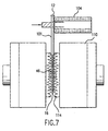
- Screws 101 are carried on the conveyor 104 through a first heating assembly 108, which includes a plurality of flame burners 110 and thermocouples 112. As shown in Fig. 7, the flame burners 110 in assembly 108 are used to heat the lower end 46 and tip 16 of each screw 101, to a temperature most preferably between 850°-1000°C . The flame 114 is applied only to these selected screw portions. An exhaust hood 117 carries away excess heat.
- each screw 101 As the screws 101 are further conveyed beyond the first heating assembly 108, the lower end and tip of each screw 101 are then quenched using a cooling assembly 116. As illustrated in Fig. 8, the cooling assembly applies a water curtain 117, or process oil, or another cooling fluid selectively to the portions of each screw which have been heated. The heated portions are preferably cooled to 70°C or less.
- the first heating assembly may increase the Rockwell R C hardness of the lower end and tip of each screw, from a starting value less than 35 (and perhaps less than 25) to a value of about 45 or higher (and perhaps 50 or higher). It may be desirable to soften the threads in the lower end to an intermediate hardness, while maintaining the high hardness of the screw tip.
- This softening called “tempering” can be accomplished by passing the hardened thread portion 46 of each screw through a second heating assembly 120.
- the second heating assembly 120 may include a plurality of smaller flame burners 122 which, as shown in Fig. 9, heat only the lower end 46 of each screw, but not the screw tip, to a temperature of about 400 0 -550°C as determined by thermocouple sensor 123. This secondary heating step softens the lower portion 46 of each screw to an intermediate Rockwell R C value of about 35-45.
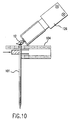
- the head portions 12 are selectively heat treated using a third heating assembly 124 having one or more flame burners 126, and thermocouple 127. As shown in Fig. 10, the burners in the third heating assembly 124 aim the flame heat selectively toward the head portions 12. The head portions are most preferably heated to about 850°-1000°C. The head portions 12 are then selectively quenched using a cooling assembly 128 which, as shown in Fig. 11, directs water or another quenching fluid directly to the head portions 12. The head portions thus treated may have a Rockwell R C hardness value of about 45 or higher, perhaps about 50 or higher. The screws 101 may then exit the apparatus 100 for packaging or other use.
- a third heating assembly 124 having one or more flame burners 126, and thermocouple 127.
- the burners in the third heating assembly 124 aim the flame heat selectively toward the head portions 12.
- the head portions are most preferably heated to about 850°-1000°C.
- the head portions 12 are then selectively quenched using a cooling assembly 128
Abstract
Description
- This invention relates to carbon steel screws and similar fasteners having selectively hardened portions to create desired properties and behavior, and a method for making the selectively hardened screws.
- Stainless steel screws having selectively hardened regions are known from U.S. Patent 3,376,780, which discloses a stainless steel screw having selectively hardened screw flight crests and a selectively hardened head region for insertion of a screwdriver. These regions are harder than the remaining portions of the screw. The stainless steel screw has a carbon content not exceeding 0.20 % by weight, a chromium content of 10-25 % by weight, a nickel content of 5-20 % by weight, a copper content of 1-5 % by weight, and an aluminum content of 0.25-2.5 % by weight. The hardening is accomplished by cold-working the stainless steel at about 350°-500° C, and by age-hardening at about 550°-700° C. The hardening is the greatest in the regions of the greatest cold-working.
- U.S. Patent 4,295,351 discloses a stainless steel screw whose flight crests have been selectively hardened. The selective hardening is achieved by aggressive cold-working of the precursor fastener blanks, at sub-zero temperatures, during formation of the threads. Another selectively hardened stainless steel screw is disclosed in U.S. Patent 4,289,006.
- U.S. Patent 2,229,565, discloses a socket screw whose head portion is selectively hardened. The head portion of the screw is rapidly heated by induction to an elevated temperature. The entire screw is then quenched, causing hardening of the heated portion. The resulting screw may have a Rockwell "C" hardness ("R C ") of about 48-50 in the head region, and a lower R C of about 30-35 in the remaining portions.
- U.S. Patent 5, 755, 542 discloses a screw having selectively hardened threads at a lower end of the screw shank, and a selectively hardened tip. U.S. Patent 5,605,423 discloses a stud having selectively hardened threads at a lower end of the stud, and a selectively hardened tip.
- Certain standard carbon steel screws (having a single slot in the head) and cross-recessed screws (having two slots in the head which cross each other) can only be exposed to a limited driving torque from a driving tool (e.g. screwdriver). When the head slots are exposed to excessive turning force, the slots become enlarged and damaged, so that the driving tool can no longer effectively engage the slots.
- Consideration has been given to hardening the head portion of screws to strengthen the slots. However, the hardening can cause the head and upper shank portion to become excessively brittle, resulting in 1) the head breaking from the screw shaft when excessive turning force is applied, 2) hydrogen embrittlement if the screws are plated, and 3) head-popping caused by thermal expansion and contraction of the substrate(s) to which the screw is applied, which creates stress that cannot be relieved by screw elongation. Also, selective heating of the head portion to cause hardening can result in distortion of the screw when the entire screw (having a varying temperature profile) is exposed to a quenching fluid.
- The present invention is directed to a selectively hardened carbon steel screw having a differential hardness profile within the head portion. A screw is provided having a head portion, a shank portion below the head, and a lower end portion or tip. The head portion has a top surface, a bottom surface, a center, an outer rim, and at least one slot in the center for engaging a driving tool. The invention also encompasses a carbon steel screw having a selectively hardened tip which facilitates initial penetration of the screw into a substrate.
- In accordance with the invention, the head portion is selectively hardened in the center and at the top so that the center of the head portion near the top is harder than the bottom of the head portion and the adjacent screw shank. Put another way, the ridges and walls defining the slot are selectively hardened at the top to provide strength and hardness and reduce damage caused by a driving tool. Yet the bottom of the head portion and the adjacent shank remain relatively soft and pliable, so that the head portion does not break away from the shank when high torque or high stress, such as shear stress, is applied.
- The invention also includes a method for selectively hardening the head portion at the center and near the top. A source of heat, which can be a flame jet, is applied directly to the top and center of the head portion, causing that region to reach a temperature above 700°C. The maximum temperature reached at the top and center of the head portion is higher than the temperature reached at the bottom of the head portion or adjacent portion of the screw shaft. Then, the screw can be differentially quenched to reduce or prevent distortion. Differential quenching can be accomplished by aiming a quenching fluid directly at the top center of the head portion, to achieve maximum quenching at the hottest region. The quench fluid can then be allowed to flow from the head portion to the remaining portions of the screw, where less quenching is wanted.
- The invention includes a similar technique for selectively heat treating and quenching the tip of a screw, to cause localized hardening.
-
- Fig. 1 is a sectional view of a screw of the invention having selected hardening in the head region.
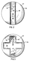
- Fig. 2 is a top view of the screw of Fig. 1.
- Fig. 3 is a top view of another embodiment of the screw of the invention.
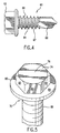
- Fig. 4 illustrates a drill point screw which can be selectively hardened according to the invention.
- Fig. 5 illustrates a hex-head screw which can be selectively hardened according to the invention.
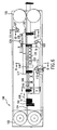
- Fig. 6 is a schematic view of a heating apparatus for making selectively hardened screws.
- Figs. 7-11 are sectional views taken along lines 7-7, 8-8, 9-9, 10-10, and 11-11 in Fig. 6.
-
- Referring to Fig. 1, a
carbon steel screw 10 of the invention has ahead portion 12, ashank 14 below the head, and ascrew tip 16 at anend 46 of the shank opposite the head. A plurality of screw flights orthreads 18 havingpeaks 20 andvalleys 22 between them, wind around the outer rim of theshank 14 andtip 16. - Referring to Figs. 1-3, the
head portion 12 has atop surface 24, abottom 26, acenter region 28, and anouter rim 30. Thecenter region 28 includes a recess, either asingle slot 32 for receiving a standard screwdriver or similar tool, or a pair of intersectingslots - Each slot is defined by a pair of opposing, generally
upright walls top surface 24 atridges slot floor 44 atjunctions ridges slot floor 44. Theslot floor 44 may actually be located below thescrew head 12 and in theadjacent shank 14, indicating a slot depth greater than the thickness of the screw head as shown in Fig. 1. Alternatively, theslot floor 44 may be about even with thebottom 26 ofhead 12, or may be above thebottom 26 ofhead 12, in which case the slot 32 (orslots 32 and 34) are located entirely within thehead portion 12. - The
screws 10 of the invention are selectively hardened to create a differential hardness profile within thehead portion 12. A flame jet or other source of heat is applied directly to theupper surface 24 in the vicinity ofcenter region 28, so that the heating is greatest at the highest points near the center, namely theridges slots 32 and 34). Theridges ridges 40 and 42) to transform from a ferritic perlitic metallurgical structure to an austenitic metallurgical structure. The heating is sufficiently directed, and for a short enough period of time, that thebottom 26 ofhead 12 and adjacent portion ofshaft 14 do not experience this transformation. - The
screws 10 are then quenched by directing a quenching fluid to the portion ofhead 12 which experienced the greatest heating. The quenching fluid may be water or another liquid or gas, and may be poured, sprayed, sprayed with air assist, or otherwise applied directly to theupper surface 24 in the vicinity of thecenter region 28. The applied quenching fluid may then flow down over the head, so as to have a lesser quenching impact on portions of the screw which experienced less heating. The selective quenching causes the hottest portions (on and aroundridges 40 and 42) to transform from the austenitic metallurgical structure to a martensitic structure, which is hardened but untempered. Thebottom portion 26 ofscrew head 12, and the adjacent portion ofshank 14, remain substantially in the ferritic perlitic state, which is softer and more pliable. By selectively quenching the hottest portion of thehead 12 to a greater extent than the cooler portions, distortion of the screw due to quenching is minimized. - The quenching fluid may have a temperature of about 4°-100°C, preferably about 10°-70°C, more preferably about 15°-40°C. Tap water or other process water is suitable. Other quenching media may include oil or gas. The quench time need not be more than about 30 seconds, and may be about 3-10 seconds. The screw head may still be warm after quenching in order to facilitate drying.
- The resulting selectively hardened carbon steel screw has a hardness differential of at least about 10 Rockwell "C" ("R C ") units within the head portion itself. The
ridges head 12 should have an R C of at least about 45, preferably at least about 50, more preferably at least about 55. The bottom 26 of thehead 12, and the upper region ofshank 14, should have an R C no greater than about 35. - The remaining portions of
screw head 12 may have an R C value closer to the R C of theridges walls slots 32 and 34) should have an R C of at least about 45 near the top and near the center, yet may have an R C of about 35 or lower near thejunctions slot floor 44. Theslot floor 44 may have an R C of about 35 or less. Theupper surface 24 may have an R C of at least about 45 close to the ridges and close to the center, and may or may not have a lower R C closer to therim 30. - By selectively hardening the
screw head 12 in this fashion, theslot 32 is provided with additional strength and hardness which reduces deformation and damage when a screwdriver or similar tool is applied at high torque. By allowing the bottom 26,head 12 andadjacent shank 14 to remain softer, the possibility of the head breaking away due to high torque or high shear stress is reduced. The invention is particularly useful for roofing screws, and other screws which have long shafts and/or which are driven into resistant substrates, because these screws are routinely subjected to high shear stress levels due to extreme temperature variations experienced on a roof. - The
screw 10 should be constructed from a fairly low carbon steel. Suitable carbon contents may range from about 0.08-0.50% by weight of the steel, with a preferred range of about 0.18-0.35% by weight of the steel. The carbon should be sufficient to facilitate hardening of the steel by heat treatment, yet not high enough to facilitate work hardening during cold heading, pointing, or thread rolling of the screw. Put another way, thescrew 10 of the invention is selectively heat hardened, and preferably, not work hardened. - In another embodiment illustrated in Fig. 4, the selectively hardened screw of the invention may be a drill tip screw. One type of
drill tip screw 60 includes ahexagonal head portion 62, a threadedshaft 64 including one or morespiral threads 66, and adrill point 68 which can be used to tap and drill at least a portion of thescrew 60 into a substrate. Thehead portion 62 may be selectively hardened on its exterior faces using techniques described above for improved strength and integrity. Furthermore, thetip 68, and aportion 67 ofshank 64 encompassing the firstfew threads 66 above thetip 68, may be selectively heat treated and hardened in order to facilitate initial penetration of thescrew 60 into a substrate, and initial thread tapping. A roofing screw may be hardened at the tip and just above the tip, in order to overcome the need to drill a hole in the substrate to get the screw started. - Referring to Fig. 4, the
end portion 67 ofscrew 60, defined as the lower region ofshank 64 adjacent the tip, may be selectively hardened along with thetip 68 by initially applying a flame jet or other heat source directly to theend region 67 andtip 68.End region 67 andtip 68 are heated to at least about 700°C, preferably about 800°-1100°C, more preferably about 850°-1000°C. The selective heating causesend region 67 andtip 68 to change from a ferritic perlitic metallurgical structure to an austenitic metallurgical structure. Then, endregion 67 andtip 68 are selectively quenched by dipping or directing a quenching fluid directly at them. The selective quenching (which causes even cooling around the screw, but differential quenching along its length) converts the austenitic metallurgical structure to a martensitic metallurgical structure in the heated region, which is untempered but hard. The quenching fluid may be water, and may be applied at the temperatures and quench times stated above for the head portion - The
end regions 67 andtips 68 ofscrews 60 should be hardened to an R C value of at least about 45, preferably at least about 50, more preferably at least about 55. The untreated region ofshank 64 aboveend region 67 may have an R C at least about 10 units lower than the hardened end region, and may have an R C of about 35 or less, perhaps 25 or less. - The
hardened region 67 of the shank may then be tempered to yield a hardness value R C of between about 35-45, which is higher than the starting R C value yet lower than the selectively hardened value. Tempering can be accomplished by reheating the selectively hardenedregion 67 to about 300°-600°C, preferably about 400°-550°C . Preferably, thetip 68 is not tempered, but is instead maintained at its maximum hardness. Thespiral threads 66 may also be case hardened (i.e. hardened on their exterior) to reduce damage when the screw is driven into a substrate. This is particularly useful in the case of long drill screws used for roofing. - In another embodiment, the selectively hardened screw may be a hex-head screw having a hexagonal head portion for receiving a driving tool. Referring to Fig. 5, the
screw 70 has ahead 74, with atop surface 76. Thehead 74 also has a hexagonalouter surface 80 composed of six rectangular flat surfaces 82. In the embodiment shown, apermanent washer 84 is positioned between thehead 74 and the elongated threadedshank 86 of the screw. - In accordance with the invention, selected portions of hex-
head screw 70 may be hardened using the techniques described above. The top of head portion 72, which receives the driving tool, may be selectively hardened to provide better resistance to damage and wear. By hardening the sixouter faces 82 of the head portion, the performance of the screw and driving tool can be enhanced due to improved interaction using a socket driving tool. - Again, the drill point screw of Fig. 4 and hex-head screw of Fig. 5 may be fabricated from carbon steel having carbon contents as described above. The non-hardened screw portions may have an R C value of about 35 or less. The selectively hardened portions may have an R C value of at least about 45, preferably at least about 50, more preferably, at least about 55.
- The head and end regions of screws may be selectively hardened separately, using different processes, or may be treated in a single integrated process. Figs. 6-11 schematically illustrate an
apparatus 100 useful for heat treating selected portions of a large number of screws on a continuous basis. Referring to Fig. 6,apparatus 100 includes atransport mechanism 102 which cooperates with and moves ascrew conveyor 104, which may be a link chain, in the direction ofarrow 106.Screws 101, which can have a variety of lengths, are supported in theconveyor 104 below theirrespective head portions 12. -
Screws 101 are carried on theconveyor 104 through a first heating assembly 108, which includes a plurality offlame burners 110 andthermocouples 112. As shown in Fig. 7, theflame burners 110 in assembly 108 are used to heat thelower end 46 andtip 16 of eachscrew 101, to a temperature most preferably between 850°-1000°C . Theflame 114 is applied only to these selected screw portions. Anexhaust hood 117 carries away excess heat. - As the
screws 101 are further conveyed beyond the first heating assembly 108, the lower end and tip of eachscrew 101 are then quenched using acooling assembly 116. As illustrated in Fig. 8, the cooling assembly applies awater curtain 117, or process oil, or another cooling fluid selectively to the portions of each screw which have been heated. The heated portions are preferably cooled to 70°C or less. - The first heating assembly, followed by cooling, may increase the Rockwell R C hardness of the lower end and tip of each screw, from a starting value less than 35 (and perhaps less than 25) to a value of about 45 or higher (and perhaps 50 or higher). It may be desirable to soften the threads in the lower end to an intermediate hardness, while maintaining the high hardness of the screw tip. This softening, called "tempering", can be accomplished by passing the
hardened thread portion 46 of each screw through asecond heating assembly 120. Thesecond heating assembly 120 may include a plurality ofsmaller flame burners 122 which, as shown in Fig. 9, heat only thelower end 46 of each screw, but not the screw tip, to a temperature of about 4000-550°C as determined bythermocouple sensor 123. This secondary heating step softens thelower portion 46 of each screw to an intermediate Rockwell R C value of about 35-45. - As the
screws 101 are further conveyed, thehead portions 12 are selectively heat treated using athird heating assembly 124 having one ormore flame burners 126, andthermocouple 127. As shown in Fig. 10, the burners in thethird heating assembly 124 aim the flame heat selectively toward thehead portions 12. The head portions are most preferably heated to about 850°-1000°C. Thehead portions 12 are then selectively quenched using acooling assembly 128 which, as shown in Fig. 11, directs water or another quenching fluid directly to thehead portions 12. The head portions thus treated may have a Rockwell R C hardness value of about 45 or higher, perhaps about 50 or higher. Thescrews 101 may then exit theapparatus 100 for packaging or other use.
Claims (27)
- A selectively hardened carbon steel screw comprising a screw head (12), a shank (14) having a first end adjacent the head (12) and a second end (46), and a screw tip (16) adjacent the second end (46) of the shank (14) ;the screw head (12) including a top surface (24), a bottom (26), a center region (28), an outer rim (30) and a recess (32, 34), in the center region (28) for receiving a driving tool ;the screw head (12) having a martensitic metallurgical structure on the top surface (24) in the center region (28), and a ferritic perlitic metallurgical structure on the bottom (26).
- The screw of claim 1, wherein the shank (14) has a ferritic perlitic metallurgical structure.
- The screw of claim 1, wherein the shank (14) has a ferritic perlitic metallurgical structure at the first end and a martensitic metallurgical structure at the second end (46), and the screw tip (16) has a martensitic metallurgical structure.
- The screw of claim 1, comprising about 0.15-0.50 % by weight carbon in the steel.
- The screw of claim 1, comprising about 0.18-0.35 % by weight carbon in the steel.
- A selectively hardened carbon steel screw comprising a screw head (62), a shank (64) having a first end adjacent the head (62) and a second end (67), and a screw tip (68) adjacent the second end (67) of the shank (64) ;the screw head (62) including an upper selectively hardened portion and a lower portion which has not been hardened ;the shank (64) including an upper portion which has not been hardened.
- The screw of claim 6, wherein the screw tip (68) is also selectively hardened.
- The screw of claim 7, wherein the shank further comprises a lower selectively hardened portion (67).
- The screw of claim 7, wherein the selectively hardened screw tip (68) has a Rockwell "C" hardness of at least about 45.
- The screw of claim 9, wherein the Rockwell "C" hardness is at least about 50.
- The screw of claim 8, wherein the selectively hardened portion (67) of the shank (64) has a Rockwell "C" hardness of about 35-45.
- A selectively hardened carbon steel screw comprising a screw head (12), a screw shank (14) having a first end adjacent the head (12) and a second end (46), and a screw tip (16) adjacent the second end (46) of the shank ;
wherein a portion or portions of the screw are selectively hardened by heat treatment to an elevated temperature, followed by quenching, to yield a Rockwell "C" hardness at least about 10 units higher than a remaining portion or portions of the screw not selectively hardened. - The screw of claim 12, wherein an upper portion (24) of the head (12) is selectively hardened.
- The screw of claim 13, wherein a lower portion (26) of the head is not hardened.
- The screw of claim 12, wherein the screw tip (16) is selectively hardened.
- The screw of claim 15, wherein the second end (46) of the shank (14) is first selectively hardened and then tempered.
- The screw of claim 12, wherein the elevated temperature is at least about 700°C.
- The screw of claim 17, wherein the elevated temperature is about 800°-1100°C.
- The screw of claim 18, wherein the elevated temperature is about 850°C-1000°C.
- The screw of claim 12, wherein the selectively hardened portion or portions are selectively quenched.
- The screw of claim 12, wherein the head (12) comprises a single slot (32) having a hardened upper portion.
- The screw of claim 12, wherein the head (12) comprises two slots (32, 34) which cross each other, having hardened upper portions.
- The screw of claim 12, wherein the head comprises a hex-head (62).
- The screw of claim 23, wherein the hex-head (62) comprises a hardened recessed area.
- The screw of claim 23, wherein the hex-head (62) comprises hardened outer surfaces.
- The screw of claim 12, wherein the screw tip comprises a hardened drill tip (68).
- The screw of claim 12, wherein the shank comprises case hardened threads (66).
Applications Claiming Priority (2)
| Application Number | Priority Date | Filing Date | Title |
|---|---|---|---|
| US09/229,435 US6109851A (en) | 1999-01-13 | 1999-01-13 | Screws having selected heat treatment and hardening |
| US229435 | 1999-01-13 |
Publications (2)
| Publication Number | Publication Date |
|---|---|
| EP1020536A1 true EP1020536A1 (en) | 2000-07-19 |
| EP1020536B1 EP1020536B1 (en) | 2009-10-07 |
Family
ID=22861242
Family Applications (1)
| Application Number | Title | Priority Date | Filing Date |
|---|---|---|---|
| EP00400078A Expired - Lifetime EP1020536B1 (en) | 1999-01-13 | 2000-01-13 | Screws having selected heat treatment and hardening |
Country Status (12)
| Country | Link |
|---|---|
| US (2) | US6109851A (en) |
| EP (1) | EP1020536B1 (en) |
| JP (1) | JP4741051B2 (en) |
| KR (1) | KR20000052615A (en) |
| CN (2) | CN1116528C (en) |
| AT (1) | ATE445025T1 (en) |
| AU (1) | AU729105B2 (en) |
| CA (1) | CA2291577C (en) |
| DE (1) | DE60043083D1 (en) |
| DK (1) | DK1020536T3 (en) |
| NZ (1) | NZ502265A (en) |
| TW (1) | TW440657B (en) |
Cited By (11)
| Publication number | Priority date | Publication date | Assignee | Title |
|---|---|---|---|---|
| KR20000052615A (en) * | 1999-01-13 | 2000-08-25 | 토마스 더블유. 버크맨 | Screws having selected heat treatment and hardening |
| WO2003046229A1 (en) * | 2001-11-28 | 2003-06-05 | Ejot Verbindungstechnik Gmbh & Co. Kg | Fastening element made of a carbon-containing steel and method for the production thereof |
| EP1369603A1 (en) * | 2002-05-31 | 2003-12-10 | Voith Paper Patent GmbH | Screwelement, and place of junction to rotate the screw |
| EP1843093A2 (en) * | 2006-02-10 | 2007-10-10 | Yildirim Karamahmut | Burner nozzle, system, furnace and installation |
| WO2012084388A1 (en) * | 2010-12-21 | 2012-06-28 | Hilti Aktiengesellschaft | Method for producing a screw anchor and screw anchor |
| WO2013083540A1 (en) * | 2011-12-04 | 2013-06-13 | Baier & Michels Gmbh & Co. Kg | Corrosion-resistant screw, use of a screw of this type in a corrosive environment, and method for producing a screw of this type |
| WO2013131849A1 (en) * | 2012-03-09 | 2013-09-12 | Sfs Intec Holding Ag | Bolt-like fastening element, in particular drilling screw, and connection established thereby |
| CN105909647A (en) * | 2016-03-10 | 2016-08-31 | 天津市福厚盈科技有限公司 | Preparation method of beautiful screw |
| FR3043348A1 (en) * | 2015-11-09 | 2017-05-12 | Airbus Operations Sas | EXPANSION RING COMPRISING AT LEAST TWO CYLINDRICAL PORTIONS WITH DIFFERENT MECHANICAL PROPERTIES, METHOD OF MANUFACTURING SUCH EXPANSION RING, AND COLD EXPANSION METHOD USING SAID EXPANSION RING |
| CN108526826A (en) * | 2018-04-28 | 2018-09-14 | 鹏驰五金制品有限公司 | A kind of processing technology of high-strength bolt |
| WO2021185853A1 (en) * | 2020-03-16 | 2021-09-23 | Ejot Gmbh & Co. Kg | Method for producing a screw, and screw |
Families Citing this family (44)
| Publication number | Priority date | Publication date | Assignee | Title |
|---|---|---|---|---|
| DE19840298A1 (en) * | 1998-09-04 | 2000-03-16 | Ejot Verbindungstech Gmbh & Co | Self-tapping light metal screw and process for their manufacture |
| US6386810B1 (en) * | 1999-05-21 | 2002-05-14 | Hiroshi Onoe | High strength screw |
| US6332741B1 (en) * | 2000-09-19 | 2001-12-25 | Textron, Inc. | Masonry anchor device |
| DE10205031B4 (en) * | 2002-02-07 | 2004-01-08 | Hilti Ag | Method for producing a fastening element which can be driven in by means of a setting device, as well as a setting device therefor and a fastening element |
| JP4188010B2 (en) * | 2002-07-04 | 2008-11-26 | 有限会社新城製作所 | Heat resistant drill screw |
| FR2841947B1 (en) * | 2002-07-05 | 2005-04-29 | Valmex | STEEL SCREW WITH HOLLOW HEAD |
| US6908126B2 (en) * | 2002-10-15 | 2005-06-21 | Sargent Manufacturing Company | Enhanced security catch assembly for retaining a handle on a spindle |
| JP4284405B2 (en) * | 2002-10-17 | 2009-06-24 | 独立行政法人物質・材料研究機構 | Tapping screw and its manufacturing method |
| DE10315957A1 (en) * | 2003-04-08 | 2004-10-28 | Ejot Gmbh & Co. Kg | Screw with a partially hardened functional tip and process for its manufacture |
| US20050092403A1 (en) * | 2003-10-29 | 2005-05-05 | Lloyd David J. | Functionally graded aluminum alloy sheet |
| CA2484381C (en) * | 2004-10-08 | 2013-03-19 | Anne Marie Sedgwick | Supporting device |
| US9493936B2 (en) | 2004-10-08 | 2016-11-15 | Sdb Ip Holdings, Llc | System, method, and apparatus for monitoring wear in a flush valve using pressure detection |
| US7607448B2 (en) * | 2004-10-08 | 2009-10-27 | I-Con Systems, Inc. | Method for modifying a plastic body valve for use in a waste water system |
| US20100239386A1 (en) * | 2004-10-08 | 2010-09-23 | Innozinc, Inc. | Supporting device |
| US7735513B2 (en) | 2004-10-08 | 2010-06-15 | I-Con Systems, Inc. | Diaphragm valve with electronic pressure detection |
| CN100463827C (en) * | 2004-12-04 | 2009-02-25 | 浙江福林国润汽车零部件有限公司 | Automobile electric booster sterring system and its treating method for rotary shaft |
| US20070201966A1 (en) * | 2006-02-24 | 2007-08-30 | M & W Fastener Co., Ltd. | Flat head screw |
| JP2008064310A (en) * | 2006-08-11 | 2008-03-21 | Nsk Ltd | Bearing device for vehicle |
| US20080163728A1 (en) * | 2007-01-05 | 2008-07-10 | Snap-On Incorporated | Dual hardness connector |
| US20080197640A1 (en) * | 2007-02-19 | 2008-08-21 | Ronald C Clarke | Method and apparatus for driving a bolt |
| US9943934B2 (en) | 2008-10-08 | 2018-04-17 | Snap-On Incorporated | Method and tool product of differential heat treatment process |
| US8529178B2 (en) | 2010-02-19 | 2013-09-10 | Nucor Corporation | Weldless building structures |
| US9004835B2 (en) | 2010-02-19 | 2015-04-14 | Nucor Corporation | Weldless building structures |
| TW201344068A (en) * | 2012-04-24 | 2013-11-01 | Shehkai Prec Co Ltd | Manufacturing method of self-drilling screw |
| CN104100622B (en) * | 2013-04-08 | 2017-02-15 | 彭亮生 | Large-scale and high-intensity rivet connection pair and manufacturing method thereof |
| CN103644208A (en) * | 2013-11-18 | 2014-03-19 | 苏州蓝王机床工具科技有限公司 | Mechanism for connecting gear and drive shaft |
| CN104690519B (en) * | 2013-12-10 | 2018-03-13 | 全球传动科技股份有限公司 | The manufacture method of screw rod |
| TWI552815B (en) * | 2013-12-24 | 2016-10-11 | Screw thread forming method | |
| CN104141657A (en) * | 2014-07-12 | 2014-11-12 | 汤荣民 | Automobile clamping groove connecting piece and heat treatment technology thereof |
| CN104962701B (en) * | 2015-07-29 | 2017-03-08 | 山东伊莱特重工股份有限公司 | A kind of hydraulic press drift non-oxidation decarburization local strengthening Technology for Heating Processing |
| US10047561B1 (en) * | 2015-09-08 | 2018-08-14 | Philip F. Lanzafame | Adjustable ladder extension |
| US10527191B2 (en) | 2015-12-15 | 2020-01-07 | Sdb Ip Holdings, Llc | System, method, and apparatus for monitoring restroom appliances |
| US10385415B2 (en) | 2016-04-28 | 2019-08-20 | GM Global Technology Operations LLC | Zinc-coated hot formed high strength steel part with through-thickness gradient microstructure |
| US10619223B2 (en) | 2016-04-28 | 2020-04-14 | GM Global Technology Operations LLC | Zinc-coated hot formed steel component with tailored property |
| CA3211072A1 (en) | 2016-05-02 | 2017-11-02 | Asia Fastening (Us), Inc. | Double threaded standoff fastener |
| CN105821195B (en) * | 2016-06-03 | 2017-12-08 | 昆山土山建设部件有限公司 | The heat stepwise Cooling Quenching technique of thrust wheel wheel body |
| EP3276189B1 (en) * | 2016-07-29 | 2020-03-25 | KAMAX Holding GmbH & Co. KG | High-strength screw including an unhardening layer |
| DE102017101931B4 (en) * | 2017-02-01 | 2022-05-05 | Kamax Holding Gmbh & Co. Kg | High strength screw with a softened threaded end |
| US11028457B2 (en) | 2017-07-17 | 2021-06-08 | Caterpillar Inc. | Method of heat treating a fastening member |
| US11613789B2 (en) | 2018-05-24 | 2023-03-28 | GM Global Technology Operations LLC | Method for improving both strength and ductility of a press-hardening steel |
| US11612926B2 (en) | 2018-06-19 | 2023-03-28 | GM Global Technology Operations LLC | Low density press-hardening steel having enhanced mechanical properties |
| US11530469B2 (en) | 2019-07-02 | 2022-12-20 | GM Global Technology Operations LLC | Press hardened steel with surface layered homogenous oxide after hot forming |
| CN110453051B (en) * | 2019-09-16 | 2021-07-02 | 威德车业部件有限公司 | Automatic quenching equipment for bolt fastener |
| DE102020102982A1 (en) * | 2020-02-05 | 2021-08-05 | Böllhoff Verbindungstechnik GmbH | Joining element, connection structure with the joining element, manufacturing method of the joining element and corresponding connection method |
Citations (7)
| Publication number | Priority date | Publication date | Assignee | Title |
|---|---|---|---|---|
| US2086801A (en) * | 1927-08-15 | 1937-07-13 | Howard A Hayden | Process of making tappet screws |
| GB502152A (en) * | 1936-09-10 | 1939-03-10 | Werner Theodor Schaurte | Process of and apparatus for effecting local hardening of mass-production articles |
| DE684060C (en) * | 1936-09-11 | 1939-11-21 | Bauer & Schaurte | Device for the partial hardening of mass products |
| US4730970A (en) * | 1986-11-12 | 1988-03-15 | Whyco Chromium Company | Selectively hardened self drilling fasteners |
| EP0563826A1 (en) * | 1992-04-02 | 1993-10-06 | Inlex Locking Limited | Method of heat treating a zone of each of a plurality of articles |
| US5605423A (en) * | 1996-04-26 | 1997-02-25 | Elco Textron, In. | Self-drilling stud |
| US5755542A (en) * | 1996-08-06 | 1998-05-26 | Elco Textron, Inc. | Self-drilling/self-tapping fastener |
Family Cites Families (48)
| Publication number | Priority date | Publication date | Assignee | Title |
|---|---|---|---|---|
| US1462775A (en) | 1920-11-02 | 1923-07-24 | Trivelloni Angelo | Process for the manufacture of nails formed in two parts |
| US1767653A (en) | 1925-11-18 | 1930-06-24 | Scovill Manufacturing Co | Metal article |
| US2229565A (en) * | 1938-09-17 | 1941-01-21 | Standard Pressed Steel Co | Socketed metallic article |
| US2224659A (en) * | 1940-04-12 | 1940-12-10 | Clare L Brackett | Method of making self-locking screw threaded elements |
| US2590585A (en) | 1951-02-01 | 1952-03-25 | Temple Velocity Equipment Inc | Explosively actuated bonding tool |
| US3090712A (en) * | 1960-02-02 | 1963-05-21 | Ernest V Berry | Method of prestressing a crankshaft and crankshaft formed as a result thereof |
| US3301120A (en) * | 1964-11-27 | 1967-01-31 | Caterpillar Tractor Co | Tempered threaded members and method of making |
| US3344817A (en) * | 1965-05-28 | 1967-10-03 | Illinois Tool Works | Method of selectively hardening a corrosion resistant part and the article produced thereby |
| US3376780A (en) * | 1966-09-19 | 1968-04-09 | Armco Steel Corp | Stainless steel, products and method |
| US3769103A (en) * | 1971-03-25 | 1973-10-30 | Res Eng & Mfg | Method of heat treating articles |
| US3765660A (en) * | 1972-05-15 | 1973-10-16 | Inland Steel Co | Beam quenching apparatus and method |
| US3983304A (en) * | 1973-09-19 | 1976-09-28 | Hi-Shear Corporation | Fastener with protective metal-organic base coating |
| US4021274A (en) * | 1975-03-26 | 1977-05-03 | Russell, Birdsall & Ward, Inc. | Method for heat treating by induced current |
| US4233880A (en) * | 1978-07-20 | 1980-11-18 | Illinois Tool Works Inc. | Stainless steel drill screw |
| US4295351A (en) * | 1979-01-08 | 1981-10-20 | Illinois Tool Works Inc. | Self-tapping stainless steel screw and method for producing same |
| US4289006A (en) * | 1979-01-08 | 1981-09-15 | Illinois Tool Works Inc. | Apparatus for producing threaded self-tapping stainless steel screws |
| US4583898A (en) * | 1979-11-26 | 1986-04-22 | Illinois Tool Works Inc. | Drill screw and cutters for making same |
| US4385081A (en) * | 1981-04-27 | 1983-05-24 | International Standard Electric Corporation | Process of coating an electric component with a setting artificial resin |
| US4486248A (en) * | 1982-08-05 | 1984-12-04 | The Algoma Steel Corporation Limited | Method for the production of improved railway rails by accelerated cooling in line with the production rolling mill |
| GB8402191D0 (en) * | 1984-01-27 | 1984-02-29 | Ici Plc | Coating process |
| DE3431008C2 (en) * | 1984-08-23 | 1986-10-16 | Dyckerhoff & Widmann AG, 8000 München | Heat treatment of hot rolled bars or wires |
| SE452472B (en) * | 1984-11-26 | 1987-11-30 | Lacani Ab | PROCEDURE FOR TREATMENT OF SPIKES TO ENSURE ITS EXTENSION HALL |
| JPS61130456A (en) * | 1984-11-29 | 1986-06-18 | Honda Motor Co Ltd | High-strength bolt and its production |
| US4702880A (en) * | 1986-07-07 | 1987-10-27 | O'donnell & Associates, Inc. | Process for improving resistance of split pins to stress corrosion cracking |
| US4835819A (en) * | 1986-09-15 | 1989-06-06 | Nylok Fastener Corporation | Coated fasteners and process for making the same |
| US4842890A (en) * | 1987-07-07 | 1989-06-27 | Nylok Fastener Corporation | Method for coating fasteners |
| JPS6487717A (en) * | 1987-09-30 | 1989-03-31 | Nippon Steel Corp | Production of high tensile bolt |
| US4842655A (en) * | 1988-02-16 | 1989-06-27 | O'donnell & Associates, Inc. | Process for improving resistance of metal bodies to stress corrosion cracking |
| US5178903A (en) * | 1989-09-29 | 1993-01-12 | Illinois Tool Works Inc. | Coated metal fastener and method for making same |
| US5078083A (en) * | 1989-10-17 | 1992-01-07 | Nylok Fastener Corporation | Method and apparatus for coating fasteners |
| US5033181A (en) * | 1990-06-08 | 1991-07-23 | Illinois Tool Works Inc. | Method for manufacturing nails |
| US5302068A (en) * | 1990-10-03 | 1994-04-12 | Illinois Tool Works Inc. | Fastener having recessed, non-circular head, and fastener-driving tool |
| US5120175A (en) * | 1991-07-15 | 1992-06-09 | Arbegast William J | Shape memory alloy fastener |
| ATE117742T1 (en) * | 1991-07-18 | 1995-02-15 | Daido Oxygen | SCREW MADE OF HARD STAINLESS STEEL AUSTENITIC STEEL. |
| US5391624A (en) * | 1992-02-10 | 1995-02-21 | S. C. Johnson & Son, Inc. | Thermosettable compositions |
| US5283280A (en) * | 1992-11-05 | 1994-02-01 | Tech One, Inc. | Composition and method for coating an object of interest |
| JP3340225B2 (en) * | 1993-01-12 | 2002-11-05 | 新日本製鐵株式会社 | High strength martensitic stainless steel with excellent rust resistance and drilling tapping screw |
| EP0627474B1 (en) * | 1993-05-13 | 2000-10-25 | American Cyanamid Company | Aqueous silicone coating compositions |
| US5484244A (en) * | 1994-02-07 | 1996-01-16 | Mse, Inc. | Self-locking threaded fasteners |
| CA2147939C (en) * | 1994-04-28 | 1999-07-06 | Elliott Y. Spearin | In-line application of solid lubricant to steel strip |
| US5614262A (en) * | 1994-05-02 | 1997-03-25 | Sundstrand Corporation | Method of sealing resin to an alloy casting |
| DE4441124C2 (en) * | 1994-11-18 | 1997-03-27 | Heraeus Kulzer Gmbh | Process for producing a non-stick, moisture-proof plastic coating on a base and its use |
| US5564876A (en) * | 1995-02-15 | 1996-10-15 | Illinois Tool Works Inc. | Corrosion-resistant, headed fastener, such as nail for exterior applications, and manufacturing method |
| DE19542949A1 (en) | 1995-11-17 | 1997-07-17 | Hilti Ag | Bolt for driving into hard materials |
| JP3776507B2 (en) * | 1996-05-23 | 2006-05-17 | 神鋼ボルト株式会社 | Manufacturing method of high-strength stainless steel bolts |
| JPH1036945A (en) * | 1996-07-19 | 1998-02-10 | Nippon Steel Corp | High rust resistant drilling trapping screw made of martensitic stainless steel excellent in screwing property and method for quenching the same |
| JPH1053813A (en) * | 1996-08-09 | 1998-02-24 | O & K:Kk | Production of non-tempered high tensile strength bolt |
| US6109851A (en) * | 1999-01-13 | 2000-08-29 | Illinois Tool Works Inc. | Screws having selected heat treatment and hardening |
-
1999
- 1999-01-13 US US09/229,435 patent/US6109851A/en not_active Expired - Lifetime
- 1999-12-06 CA CA002291577A patent/CA2291577C/en not_active Expired - Lifetime
- 1999-12-29 KR KR1019990064443A patent/KR20000052615A/en active Search and Examination
-
2000
- 2000-01-11 NZ NZ502265A patent/NZ502265A/en not_active IP Right Cessation
- 2000-01-12 CN CN00100158A patent/CN1116528C/en not_active Expired - Lifetime
- 2000-01-12 CN CNB031206379A patent/CN1303228C/en not_active Expired - Lifetime
- 2000-01-12 JP JP2000006321A patent/JP4741051B2/en not_active Expired - Fee Related
- 2000-01-12 AU AU10031/00A patent/AU729105B2/en not_active Expired
- 2000-01-13 AT AT00400078T patent/ATE445025T1/en not_active IP Right Cessation
- 2000-01-13 EP EP00400078A patent/EP1020536B1/en not_active Expired - Lifetime
- 2000-01-13 DE DE60043083T patent/DE60043083D1/en not_active Expired - Lifetime
- 2000-01-13 DK DK00400078.2T patent/DK1020536T3/en active
- 2000-03-07 TW TW089100393A patent/TW440657B/en not_active IP Right Cessation
- 2000-05-15 US US09/571,046 patent/US6364972B1/en not_active Expired - Lifetime
Patent Citations (7)
| Publication number | Priority date | Publication date | Assignee | Title |
|---|---|---|---|---|
| US2086801A (en) * | 1927-08-15 | 1937-07-13 | Howard A Hayden | Process of making tappet screws |
| GB502152A (en) * | 1936-09-10 | 1939-03-10 | Werner Theodor Schaurte | Process of and apparatus for effecting local hardening of mass-production articles |
| DE684060C (en) * | 1936-09-11 | 1939-11-21 | Bauer & Schaurte | Device for the partial hardening of mass products |
| US4730970A (en) * | 1986-11-12 | 1988-03-15 | Whyco Chromium Company | Selectively hardened self drilling fasteners |
| EP0563826A1 (en) * | 1992-04-02 | 1993-10-06 | Inlex Locking Limited | Method of heat treating a zone of each of a plurality of articles |
| US5605423A (en) * | 1996-04-26 | 1997-02-25 | Elco Textron, In. | Self-drilling stud |
| US5755542A (en) * | 1996-08-06 | 1998-05-26 | Elco Textron, Inc. | Self-drilling/self-tapping fastener |
Cited By (12)
| Publication number | Priority date | Publication date | Assignee | Title |
|---|---|---|---|---|
| KR20000052615A (en) * | 1999-01-13 | 2000-08-25 | 토마스 더블유. 버크맨 | Screws having selected heat treatment and hardening |
| WO2003046229A1 (en) * | 2001-11-28 | 2003-06-05 | Ejot Verbindungstechnik Gmbh & Co. Kg | Fastening element made of a carbon-containing steel and method for the production thereof |
| EP1369603A1 (en) * | 2002-05-31 | 2003-12-10 | Voith Paper Patent GmbH | Screwelement, and place of junction to rotate the screw |
| EP1843093A2 (en) * | 2006-02-10 | 2007-10-10 | Yildirim Karamahmut | Burner nozzle, system, furnace and installation |
| EP1843093A3 (en) * | 2006-02-10 | 2009-04-22 | Yildirim Karamahmut | Burner nozzle, system, furnace and installation |
| WO2012084388A1 (en) * | 2010-12-21 | 2012-06-28 | Hilti Aktiengesellschaft | Method for producing a screw anchor and screw anchor |
| WO2013083540A1 (en) * | 2011-12-04 | 2013-06-13 | Baier & Michels Gmbh & Co. Kg | Corrosion-resistant screw, use of a screw of this type in a corrosive environment, and method for producing a screw of this type |
| WO2013131849A1 (en) * | 2012-03-09 | 2013-09-12 | Sfs Intec Holding Ag | Bolt-like fastening element, in particular drilling screw, and connection established thereby |
| FR3043348A1 (en) * | 2015-11-09 | 2017-05-12 | Airbus Operations Sas | EXPANSION RING COMPRISING AT LEAST TWO CYLINDRICAL PORTIONS WITH DIFFERENT MECHANICAL PROPERTIES, METHOD OF MANUFACTURING SUCH EXPANSION RING, AND COLD EXPANSION METHOD USING SAID EXPANSION RING |
| CN105909647A (en) * | 2016-03-10 | 2016-08-31 | 天津市福厚盈科技有限公司 | Preparation method of beautiful screw |
| CN108526826A (en) * | 2018-04-28 | 2018-09-14 | 鹏驰五金制品有限公司 | A kind of processing technology of high-strength bolt |
| WO2021185853A1 (en) * | 2020-03-16 | 2021-09-23 | Ejot Gmbh & Co. Kg | Method for producing a screw, and screw |
Also Published As
| Publication number | Publication date |
|---|---|
| AU729105B2 (en) | 2001-01-25 |
| CA2291577C (en) | 2004-04-27 |
| TW440657B (en) | 2001-06-16 |
| CN1442620A (en) | 2003-09-17 |
| DE60043083D1 (en) | 2009-11-19 |
| CN1116528C (en) | 2003-07-30 |
| NZ502265A (en) | 2001-04-27 |
| AU1003100A (en) | 2000-07-20 |
| CN1260450A (en) | 2000-07-19 |
| US6364972B1 (en) | 2002-04-02 |
| JP2000230527A (en) | 2000-08-22 |
| DK1020536T3 (en) | 2010-02-15 |
| EP1020536B1 (en) | 2009-10-07 |
| CN1303228C (en) | 2007-03-07 |
| KR20000052615A (en) | 2000-08-25 |
| US6109851A (en) | 2000-08-29 |
| CA2291577A1 (en) | 2000-07-13 |
| ATE445025T1 (en) | 2009-10-15 |
| JP4741051B2 (en) | 2011-08-03 |
Similar Documents
| Publication | Publication Date | Title |
|---|---|---|
| EP1020536B1 (en) | Screws having selected heat treatment and hardening | |
| CN101501350A (en) | High performance thread forming screw | |
| JP2009533635A5 (en) | ||
| EP2397568B1 (en) | Blind fastener and manufacturing method therefor | |
| AU2003234913A1 (en) | Heat resistant drill screw | |
| EP1213443A3 (en) | A high strength steam turbine rotor and it's methods of fabricating | |
| JP2004060003A (en) | Method for producing link for endless track | |
| US8273188B2 (en) | Constant velocity universal joint component and manufacturing method thereof | |
| KR100317712B1 (en) | Carburizing heat treatment method and carburizing heat transfer member | |
| MXPA00000476A (en) | Screws having selected heat treatment and hardening | |
| JPS629162B2 (en) | ||
| KR0138441B1 (en) | Surface hardening method of forged steel product | |
| SU1731868A1 (en) | Method of heat treatment of massive steel parts having threaded sections | |
| Prokoshkina et al. | Martensite transformations and thermal stability of hardening in nitrogen-containing Cr-Ni steels | |
| CN1213156C (en) | Manufature for reciprocating ball steering gear screw rod | |
| JPH10298716A (en) | Work roll having small diameter | |
| Yamada et al. | Strength and toughness on the forge quenched steels | |
| Bakhmatov | The Effect of Cooling and Repeat Heating During Hardening on the Structure and Properties of Carbonitrided Parts of 25 KhGM Steel | |
| Nakonieczny et al. | Relations between the properties of a core and surface layer for various failure criteria | |
| Takahashi et al. | Strengthening and toughening of low-carbon high-strength steels by ausforming | |
| Ozaki et al. | Austenitization and carbide dissolution of high speed tool steel JIS-SKH 51 in short time heating | |
| Foley et al. | Tempering response of direct-quenched and reheat-and-quenched low- carbon martensitic steels | |
| Miokovic et al. | Effect of laser hardening with cyclic time-temperature-changes on the surface zone of quenched and tempered AISI 4140 | |
| Nguyen-Duy et al. | Effect of the tempering temperature on the fracture toughness of two steels and their fracture morphologies | |
| Dong et al. | The effect of tempering temperature on properties of an armour steel |
Legal Events
| Date | Code | Title | Description |
|---|---|---|---|
| PUAI | Public reference made under article 153(3) epc to a published international application that has entered the european phase |
Free format text: ORIGINAL CODE: 0009012 |
|
| AK | Designated contracting states |
Kind code of ref document: A1 Designated state(s): AT BE CH CY DE DK ES FI FR GB GR IE IT LI LU MC NL PT SE |
|
| AX | Request for extension of the european patent |
Free format text: AL;LT;LV;MK;RO;SI |
|
| 17P | Request for examination filed |
Effective date: 20010111 |
|
| AKX | Designation fees paid |
Free format text: AT BE CH CY DE DK ES FI FR GB GR IE IT LI LU MC NL PT SE |
|
| 17Q | First examination report despatched |
Effective date: 20031110 |
|
| APBN | Date of receipt of notice of appeal recorded |
Free format text: ORIGINAL CODE: EPIDOSNNOA2E |
|
| APBR | Date of receipt of statement of grounds of appeal recorded |
Free format text: ORIGINAL CODE: EPIDOSNNOA3E |
|
| APAA | Appeal reference recorded |
Free format text: ORIGINAL CODE: EPIDOS REFN |
|
| APBT | Appeal procedure closed |
Free format text: ORIGINAL CODE: EPIDOSNNOA9E |
|
| GRAP | Despatch of communication of intention to grant a patent |
Free format text: ORIGINAL CODE: EPIDOSNIGR1 |
|
| APAF | Appeal reference modified |
Free format text: ORIGINAL CODE: EPIDOSCREFNE |
|
| GRAS | Grant fee paid |
Free format text: ORIGINAL CODE: EPIDOSNIGR3 |
|
| GRAA | (expected) grant |
Free format text: ORIGINAL CODE: 0009210 |
|
| AK | Designated contracting states |
Kind code of ref document: B1 Designated state(s): AT BE CH CY DE DK ES FI FR GB GR IE IT LI LU MC NL PT SE |
|
| REG | Reference to a national code |
Ref country code: GB Ref legal event code: FG4D |
|
| REG | Reference to a national code |
Ref country code: CH Ref legal event code: EP |
|
| REG | Reference to a national code |
Ref country code: IE Ref legal event code: FG4D |
|
| REF | Corresponds to: |
Ref document number: 60043083 Country of ref document: DE Date of ref document: 20091119 Kind code of ref document: P |
|
| REG | Reference to a national code |
Ref country code: DK Ref legal event code: T3 |
|
| NLV1 | Nl: lapsed or annulled due to failure to fulfill the requirements of art. 29p and 29m of the patents act | ||
| PG25 | Lapsed in a contracting state [announced via postgrant information from national office to epo] |
Ref country code: ES Free format text: LAPSE BECAUSE OF FAILURE TO SUBMIT A TRANSLATION OF THE DESCRIPTION OR TO PAY THE FEE WITHIN THE PRESCRIBED TIME-LIMIT Effective date: 20100118 Ref country code: PT Free format text: LAPSE BECAUSE OF FAILURE TO SUBMIT A TRANSLATION OF THE DESCRIPTION OR TO PAY THE FEE WITHIN THE PRESCRIBED TIME-LIMIT Effective date: 20100208 Ref country code: FI Free format text: LAPSE BECAUSE OF FAILURE TO SUBMIT A TRANSLATION OF THE DESCRIPTION OR TO PAY THE FEE WITHIN THE PRESCRIBED TIME-LIMIT Effective date: 20091007 Ref country code: SE Free format text: LAPSE BECAUSE OF FAILURE TO SUBMIT A TRANSLATION OF THE DESCRIPTION OR TO PAY THE FEE WITHIN THE PRESCRIBED TIME-LIMIT Effective date: 20091007 |
|
| PG25 | Lapsed in a contracting state [announced via postgrant information from national office to epo] |
Ref country code: AT Free format text: LAPSE BECAUSE OF FAILURE TO SUBMIT A TRANSLATION OF THE DESCRIPTION OR TO PAY THE FEE WITHIN THE PRESCRIBED TIME-LIMIT Effective date: 20091007 Ref country code: BE Free format text: LAPSE BECAUSE OF FAILURE TO SUBMIT A TRANSLATION OF THE DESCRIPTION OR TO PAY THE FEE WITHIN THE PRESCRIBED TIME-LIMIT Effective date: 20091007 |
|
| PG25 | Lapsed in a contracting state [announced via postgrant information from national office to epo] |
Ref country code: NL Free format text: LAPSE BECAUSE OF FAILURE TO SUBMIT A TRANSLATION OF THE DESCRIPTION OR TO PAY THE FEE WITHIN THE PRESCRIBED TIME-LIMIT Effective date: 20091007 |
|
| PLBE | No opposition filed within time limit |
Free format text: ORIGINAL CODE: 0009261 |
|
| STAA | Information on the status of an ep patent application or granted ep patent |
Free format text: STATUS: NO OPPOSITION FILED WITHIN TIME LIMIT |
|
| PG25 | Lapsed in a contracting state [announced via postgrant information from national office to epo] |
Ref country code: MC Free format text: LAPSE BECAUSE OF NON-PAYMENT OF DUE FEES Effective date: 20100131 |
|
| REG | Reference to a national code |
Ref country code: CH Ref legal event code: PL |
|
| 26N | No opposition filed |
Effective date: 20100708 |
|
| GBPC | Gb: european patent ceased through non-payment of renewal fee |
Effective date: 20100113 |
|
| PG25 | Lapsed in a contracting state [announced via postgrant information from national office to epo] |
Ref country code: LI Free format text: LAPSE BECAUSE OF NON-PAYMENT OF DUE FEES Effective date: 20100131 Ref country code: GR Free format text: LAPSE BECAUSE OF FAILURE TO SUBMIT A TRANSLATION OF THE DESCRIPTION OR TO PAY THE FEE WITHIN THE PRESCRIBED TIME-LIMIT Effective date: 20100108 Ref country code: CH Free format text: LAPSE BECAUSE OF NON-PAYMENT OF DUE FEES Effective date: 20100131 |
|
| PG25 | Lapsed in a contracting state [announced via postgrant information from national office to epo] |
Ref country code: GB Free format text: LAPSE BECAUSE OF NON-PAYMENT OF DUE FEES Effective date: 20100113 |
|
| PG25 | Lapsed in a contracting state [announced via postgrant information from national office to epo] |
Ref country code: IE Free format text: LAPSE BECAUSE OF NON-PAYMENT OF DUE FEES Effective date: 20100113 |
|
| PG25 | Lapsed in a contracting state [announced via postgrant information from national office to epo] |
Ref country code: CY Free format text: LAPSE BECAUSE OF FAILURE TO SUBMIT A TRANSLATION OF THE DESCRIPTION OR TO PAY THE FEE WITHIN THE PRESCRIBED TIME-LIMIT Effective date: 20091007 |
|
| PG25 | Lapsed in a contracting state [announced via postgrant information from national office to epo] |
Ref country code: LU Free format text: LAPSE BECAUSE OF NON-PAYMENT OF DUE FEES Effective date: 20100113 |
|
| PGFP | Annual fee paid to national office [announced via postgrant information from national office to epo] |
Ref country code: DE Payment date: 20140129 Year of fee payment: 15 Ref country code: DK Payment date: 20140127 Year of fee payment: 15 |
|
| PGFP | Annual fee paid to national office [announced via postgrant information from national office to epo] |
Ref country code: FR Payment date: 20140117 Year of fee payment: 15 Ref country code: IT Payment date: 20140124 Year of fee payment: 15 |
|
| REG | Reference to a national code |
Ref country code: DE Ref legal event code: R119 Ref document number: 60043083 Country of ref document: DE |
|
| REG | Reference to a national code |
Ref country code: DK Ref legal event code: EBP Effective date: 20150131 |
|
| PG25 | Lapsed in a contracting state [announced via postgrant information from national office to epo] |
Ref country code: DE Free format text: LAPSE BECAUSE OF NON-PAYMENT OF DUE FEES Effective date: 20150801 |
|
| REG | Reference to a national code |
Ref country code: FR Ref legal event code: ST Effective date: 20150930 |
|
| PG25 | Lapsed in a contracting state [announced via postgrant information from national office to epo] |
Ref country code: FR Free format text: LAPSE BECAUSE OF NON-PAYMENT OF DUE FEES Effective date: 20150202 |
|
| PG25 | Lapsed in a contracting state [announced via postgrant information from national office to epo] |
Ref country code: IT Free format text: LAPSE BECAUSE OF NON-PAYMENT OF DUE FEES Effective date: 20150113 |
|
| PG25 | Lapsed in a contracting state [announced via postgrant information from national office to epo] |
Ref country code: DK Free format text: LAPSE BECAUSE OF NON-PAYMENT OF DUE FEES Effective date: 20150131 |