EP1029517A2 - Staggered endoluminal stent - Google Patents
Staggered endoluminal stent Download PDFInfo
- Publication number
- EP1029517A2 EP1029517A2 EP00100511A EP00100511A EP1029517A2 EP 1029517 A2 EP1029517 A2 EP 1029517A2 EP 00100511 A EP00100511 A EP 00100511A EP 00100511 A EP00100511 A EP 00100511A EP 1029517 A2 EP1029517 A2 EP 1029517A2
- Authority
- EP
- European Patent Office
- Prior art keywords
- frame
- prosthesis
- ring
- elements
- apices
- Prior art date
- Legal status (The legal status is an assumption and is not a legal conclusion. Google has not performed a legal analysis and makes no representation as to the accuracy of the status listed.)
- Granted
Links
Images


Classifications
-
- A—HUMAN NECESSITIES
- A61—MEDICAL OR VETERINARY SCIENCE; HYGIENE
- A61F—FILTERS IMPLANTABLE INTO BLOOD VESSELS; PROSTHESES; DEVICES PROVIDING PATENCY TO, OR PREVENTING COLLAPSING OF, TUBULAR STRUCTURES OF THE BODY, e.g. STENTS; ORTHOPAEDIC, NURSING OR CONTRACEPTIVE DEVICES; FOMENTATION; TREATMENT OR PROTECTION OF EYES OR EARS; BANDAGES, DRESSINGS OR ABSORBENT PADS; FIRST-AID KITS
- A61F2/00—Filters implantable into blood vessels; Prostheses, i.e. artificial substitutes or replacements for parts of the body; Appliances for connecting them with the body; Devices providing patency to, or preventing collapsing of, tubular structures of the body, e.g. stents
- A61F2/82—Devices providing patency to, or preventing collapsing of, tubular structures of the body, e.g. stents
- A61F2/86—Stents in a form characterised by the wire-like elements; Stents in the form characterised by a net-like or mesh-like structure
- A61F2/90—Stents in a form characterised by the wire-like elements; Stents in the form characterised by a net-like or mesh-like structure characterised by a net-like or mesh-like structure
- A61F2/91—Stents in a form characterised by the wire-like elements; Stents in the form characterised by a net-like or mesh-like structure characterised by a net-like or mesh-like structure made from perforated sheet material or tubes, e.g. perforated by laser cuts or etched holes
- A61F2/915—Stents in a form characterised by the wire-like elements; Stents in the form characterised by a net-like or mesh-like structure characterised by a net-like or mesh-like structure made from perforated sheet material or tubes, e.g. perforated by laser cuts or etched holes with bands having a meander structure, adjacent bands being connected to each other
-
- A—HUMAN NECESSITIES
- A61—MEDICAL OR VETERINARY SCIENCE; HYGIENE
- A61F—FILTERS IMPLANTABLE INTO BLOOD VESSELS; PROSTHESES; DEVICES PROVIDING PATENCY TO, OR PREVENTING COLLAPSING OF, TUBULAR STRUCTURES OF THE BODY, e.g. STENTS; ORTHOPAEDIC, NURSING OR CONTRACEPTIVE DEVICES; FOMENTATION; TREATMENT OR PROTECTION OF EYES OR EARS; BANDAGES, DRESSINGS OR ABSORBENT PADS; FIRST-AID KITS
- A61F2/00—Filters implantable into blood vessels; Prostheses, i.e. artificial substitutes or replacements for parts of the body; Appliances for connecting them with the body; Devices providing patency to, or preventing collapsing of, tubular structures of the body, e.g. stents
- A61F2/82—Devices providing patency to, or preventing collapsing of, tubular structures of the body, e.g. stents
- A61F2/86—Stents in a form characterised by the wire-like elements; Stents in the form characterised by a net-like or mesh-like structure
- A61F2/89—Stents in a form characterised by the wire-like elements; Stents in the form characterised by a net-like or mesh-like structure the wire-like elements comprising two or more adjacent rings flexibly connected by separate members
-
- A—HUMAN NECESSITIES
- A61—MEDICAL OR VETERINARY SCIENCE; HYGIENE
- A61F—FILTERS IMPLANTABLE INTO BLOOD VESSELS; PROSTHESES; DEVICES PROVIDING PATENCY TO, OR PREVENTING COLLAPSING OF, TUBULAR STRUCTURES OF THE BODY, e.g. STENTS; ORTHOPAEDIC, NURSING OR CONTRACEPTIVE DEVICES; FOMENTATION; TREATMENT OR PROTECTION OF EYES OR EARS; BANDAGES, DRESSINGS OR ABSORBENT PADS; FIRST-AID KITS
- A61F2/00—Filters implantable into blood vessels; Prostheses, i.e. artificial substitutes or replacements for parts of the body; Appliances for connecting them with the body; Devices providing patency to, or preventing collapsing of, tubular structures of the body, e.g. stents
- A61F2/95—Instruments specially adapted for placement or removal of stents or stent-grafts
-
- A—HUMAN NECESSITIES
- A61—MEDICAL OR VETERINARY SCIENCE; HYGIENE
- A61F—FILTERS IMPLANTABLE INTO BLOOD VESSELS; PROSTHESES; DEVICES PROVIDING PATENCY TO, OR PREVENTING COLLAPSING OF, TUBULAR STRUCTURES OF THE BODY, e.g. STENTS; ORTHOPAEDIC, NURSING OR CONTRACEPTIVE DEVICES; FOMENTATION; TREATMENT OR PROTECTION OF EYES OR EARS; BANDAGES, DRESSINGS OR ABSORBENT PADS; FIRST-AID KITS
- A61F2/00—Filters implantable into blood vessels; Prostheses, i.e. artificial substitutes or replacements for parts of the body; Appliances for connecting them with the body; Devices providing patency to, or preventing collapsing of, tubular structures of the body, e.g. stents
- A61F2/02—Prostheses implantable into the body
- A61F2/04—Hollow or tubular parts of organs, e.g. bladders, tracheae, bronchi or bile ducts
- A61F2/06—Blood vessels
- A61F2002/065—Y-shaped blood vessels
-
- A—HUMAN NECESSITIES
- A61—MEDICAL OR VETERINARY SCIENCE; HYGIENE
- A61F—FILTERS IMPLANTABLE INTO BLOOD VESSELS; PROSTHESES; DEVICES PROVIDING PATENCY TO, OR PREVENTING COLLAPSING OF, TUBULAR STRUCTURES OF THE BODY, e.g. STENTS; ORTHOPAEDIC, NURSING OR CONTRACEPTIVE DEVICES; FOMENTATION; TREATMENT OR PROTECTION OF EYES OR EARS; BANDAGES, DRESSINGS OR ABSORBENT PADS; FIRST-AID KITS
- A61F2/00—Filters implantable into blood vessels; Prostheses, i.e. artificial substitutes or replacements for parts of the body; Appliances for connecting them with the body; Devices providing patency to, or preventing collapsing of, tubular structures of the body, e.g. stents
- A61F2/02—Prostheses implantable into the body
- A61F2/04—Hollow or tubular parts of organs, e.g. bladders, tracheae, bronchi or bile ducts
- A61F2/06—Blood vessels
- A61F2/07—Stent-grafts
- A61F2002/075—Stent-grafts the stent being loosely attached to the graft material, e.g. by stitching
-
- A—HUMAN NECESSITIES
- A61—MEDICAL OR VETERINARY SCIENCE; HYGIENE
- A61F—FILTERS IMPLANTABLE INTO BLOOD VESSELS; PROSTHESES; DEVICES PROVIDING PATENCY TO, OR PREVENTING COLLAPSING OF, TUBULAR STRUCTURES OF THE BODY, e.g. STENTS; ORTHOPAEDIC, NURSING OR CONTRACEPTIVE DEVICES; FOMENTATION; TREATMENT OR PROTECTION OF EYES OR EARS; BANDAGES, DRESSINGS OR ABSORBENT PADS; FIRST-AID KITS
- A61F2/00—Filters implantable into blood vessels; Prostheses, i.e. artificial substitutes or replacements for parts of the body; Appliances for connecting them with the body; Devices providing patency to, or preventing collapsing of, tubular structures of the body, e.g. stents
- A61F2/82—Devices providing patency to, or preventing collapsing of, tubular structures of the body, e.g. stents
- A61F2002/828—Means for connecting a plurality of stents allowing flexibility of the whole structure
-
- A—HUMAN NECESSITIES
- A61—MEDICAL OR VETERINARY SCIENCE; HYGIENE
- A61F—FILTERS IMPLANTABLE INTO BLOOD VESSELS; PROSTHESES; DEVICES PROVIDING PATENCY TO, OR PREVENTING COLLAPSING OF, TUBULAR STRUCTURES OF THE BODY, e.g. STENTS; ORTHOPAEDIC, NURSING OR CONTRACEPTIVE DEVICES; FOMENTATION; TREATMENT OR PROTECTION OF EYES OR EARS; BANDAGES, DRESSINGS OR ABSORBENT PADS; FIRST-AID KITS
- A61F2/00—Filters implantable into blood vessels; Prostheses, i.e. artificial substitutes or replacements for parts of the body; Appliances for connecting them with the body; Devices providing patency to, or preventing collapsing of, tubular structures of the body, e.g. stents
- A61F2/82—Devices providing patency to, or preventing collapsing of, tubular structures of the body, e.g. stents
- A61F2/86—Stents in a form characterised by the wire-like elements; Stents in the form characterised by a net-like or mesh-like structure
- A61F2/90—Stents in a form characterised by the wire-like elements; Stents in the form characterised by a net-like or mesh-like structure characterised by a net-like or mesh-like structure
- A61F2/91—Stents in a form characterised by the wire-like elements; Stents in the form characterised by a net-like or mesh-like structure characterised by a net-like or mesh-like structure made from perforated sheet material or tubes, e.g. perforated by laser cuts or etched holes
- A61F2/915—Stents in a form characterised by the wire-like elements; Stents in the form characterised by a net-like or mesh-like structure characterised by a net-like or mesh-like structure made from perforated sheet material or tubes, e.g. perforated by laser cuts or etched holes with bands having a meander structure, adjacent bands being connected to each other
- A61F2002/91508—Stents in a form characterised by the wire-like elements; Stents in the form characterised by a net-like or mesh-like structure characterised by a net-like or mesh-like structure made from perforated sheet material or tubes, e.g. perforated by laser cuts or etched holes with bands having a meander structure, adjacent bands being connected to each other the meander having a difference in amplitude along the band
-
- A—HUMAN NECESSITIES
- A61—MEDICAL OR VETERINARY SCIENCE; HYGIENE
- A61F—FILTERS IMPLANTABLE INTO BLOOD VESSELS; PROSTHESES; DEVICES PROVIDING PATENCY TO, OR PREVENTING COLLAPSING OF, TUBULAR STRUCTURES OF THE BODY, e.g. STENTS; ORTHOPAEDIC, NURSING OR CONTRACEPTIVE DEVICES; FOMENTATION; TREATMENT OR PROTECTION OF EYES OR EARS; BANDAGES, DRESSINGS OR ABSORBENT PADS; FIRST-AID KITS
- A61F2/00—Filters implantable into blood vessels; Prostheses, i.e. artificial substitutes or replacements for parts of the body; Appliances for connecting them with the body; Devices providing patency to, or preventing collapsing of, tubular structures of the body, e.g. stents
- A61F2/82—Devices providing patency to, or preventing collapsing of, tubular structures of the body, e.g. stents
- A61F2/86—Stents in a form characterised by the wire-like elements; Stents in the form characterised by a net-like or mesh-like structure
- A61F2/90—Stents in a form characterised by the wire-like elements; Stents in the form characterised by a net-like or mesh-like structure characterised by a net-like or mesh-like structure
- A61F2/91—Stents in a form characterised by the wire-like elements; Stents in the form characterised by a net-like or mesh-like structure characterised by a net-like or mesh-like structure made from perforated sheet material or tubes, e.g. perforated by laser cuts or etched holes
- A61F2/915—Stents in a form characterised by the wire-like elements; Stents in the form characterised by a net-like or mesh-like structure characterised by a net-like or mesh-like structure made from perforated sheet material or tubes, e.g. perforated by laser cuts or etched holes with bands having a meander structure, adjacent bands being connected to each other
- A61F2002/91533—Stents in a form characterised by the wire-like elements; Stents in the form characterised by a net-like or mesh-like structure characterised by a net-like or mesh-like structure made from perforated sheet material or tubes, e.g. perforated by laser cuts or etched holes with bands having a meander structure, adjacent bands being connected to each other characterised by the phase between adjacent bands
- A61F2002/91541—Adjacent bands are arranged out of phase
-
- A—HUMAN NECESSITIES
- A61—MEDICAL OR VETERINARY SCIENCE; HYGIENE
- A61F—FILTERS IMPLANTABLE INTO BLOOD VESSELS; PROSTHESES; DEVICES PROVIDING PATENCY TO, OR PREVENTING COLLAPSING OF, TUBULAR STRUCTURES OF THE BODY, e.g. STENTS; ORTHOPAEDIC, NURSING OR CONTRACEPTIVE DEVICES; FOMENTATION; TREATMENT OR PROTECTION OF EYES OR EARS; BANDAGES, DRESSINGS OR ABSORBENT PADS; FIRST-AID KITS
- A61F2/00—Filters implantable into blood vessels; Prostheses, i.e. artificial substitutes or replacements for parts of the body; Appliances for connecting them with the body; Devices providing patency to, or preventing collapsing of, tubular structures of the body, e.g. stents
- A61F2/82—Devices providing patency to, or preventing collapsing of, tubular structures of the body, e.g. stents
- A61F2/86—Stents in a form characterised by the wire-like elements; Stents in the form characterised by a net-like or mesh-like structure
- A61F2/90—Stents in a form characterised by the wire-like elements; Stents in the form characterised by a net-like or mesh-like structure characterised by a net-like or mesh-like structure
- A61F2/91—Stents in a form characterised by the wire-like elements; Stents in the form characterised by a net-like or mesh-like structure characterised by a net-like or mesh-like structure made from perforated sheet material or tubes, e.g. perforated by laser cuts or etched holes
- A61F2/915—Stents in a form characterised by the wire-like elements; Stents in the form characterised by a net-like or mesh-like structure characterised by a net-like or mesh-like structure made from perforated sheet material or tubes, e.g. perforated by laser cuts or etched holes with bands having a meander structure, adjacent bands being connected to each other
- A61F2002/9155—Adjacent bands being connected to each other
- A61F2002/91558—Adjacent bands being connected to each other connected peak to peak
-
- A—HUMAN NECESSITIES
- A61—MEDICAL OR VETERINARY SCIENCE; HYGIENE
- A61F—FILTERS IMPLANTABLE INTO BLOOD VESSELS; PROSTHESES; DEVICES PROVIDING PATENCY TO, OR PREVENTING COLLAPSING OF, TUBULAR STRUCTURES OF THE BODY, e.g. STENTS; ORTHOPAEDIC, NURSING OR CONTRACEPTIVE DEVICES; FOMENTATION; TREATMENT OR PROTECTION OF EYES OR EARS; BANDAGES, DRESSINGS OR ABSORBENT PADS; FIRST-AID KITS
- A61F2220/00—Fixations or connections for prostheses classified in groups A61F2/00 - A61F2/26 or A61F2/82 or A61F9/00 or A61F11/00 or subgroups thereof
- A61F2220/0025—Connections or couplings between prosthetic parts, e.g. between modular parts; Connecting elements
- A61F2220/005—Connections or couplings between prosthetic parts, e.g. between modular parts; Connecting elements using adhesives
-
- A—HUMAN NECESSITIES
- A61—MEDICAL OR VETERINARY SCIENCE; HYGIENE
- A61F—FILTERS IMPLANTABLE INTO BLOOD VESSELS; PROSTHESES; DEVICES PROVIDING PATENCY TO, OR PREVENTING COLLAPSING OF, TUBULAR STRUCTURES OF THE BODY, e.g. STENTS; ORTHOPAEDIC, NURSING OR CONTRACEPTIVE DEVICES; FOMENTATION; TREATMENT OR PROTECTION OF EYES OR EARS; BANDAGES, DRESSINGS OR ABSORBENT PADS; FIRST-AID KITS
- A61F2220/00—Fixations or connections for prostheses classified in groups A61F2/00 - A61F2/26 or A61F2/82 or A61F9/00 or A61F11/00 or subgroups thereof
- A61F2220/0025—Connections or couplings between prosthetic parts, e.g. between modular parts; Connecting elements
- A61F2220/0058—Connections or couplings between prosthetic parts, e.g. between modular parts; Connecting elements soldered or brazed or welded
-
- A—HUMAN NECESSITIES
- A61—MEDICAL OR VETERINARY SCIENCE; HYGIENE
- A61F—FILTERS IMPLANTABLE INTO BLOOD VESSELS; PROSTHESES; DEVICES PROVIDING PATENCY TO, OR PREVENTING COLLAPSING OF, TUBULAR STRUCTURES OF THE BODY, e.g. STENTS; ORTHOPAEDIC, NURSING OR CONTRACEPTIVE DEVICES; FOMENTATION; TREATMENT OR PROTECTION OF EYES OR EARS; BANDAGES, DRESSINGS OR ABSORBENT PADS; FIRST-AID KITS
- A61F2220/00—Fixations or connections for prostheses classified in groups A61F2/00 - A61F2/26 or A61F2/82 or A61F9/00 or A61F11/00 or subgroups thereof
- A61F2220/0025—Connections or couplings between prosthetic parts, e.g. between modular parts; Connecting elements
- A61F2220/0075—Connections or couplings between prosthetic parts, e.g. between modular parts; Connecting elements sutured, ligatured or stitched, retained or tied with a rope, string, thread, wire or cable
-
- A—HUMAN NECESSITIES
- A61—MEDICAL OR VETERINARY SCIENCE; HYGIENE
- A61F—FILTERS IMPLANTABLE INTO BLOOD VESSELS; PROSTHESES; DEVICES PROVIDING PATENCY TO, OR PREVENTING COLLAPSING OF, TUBULAR STRUCTURES OF THE BODY, e.g. STENTS; ORTHOPAEDIC, NURSING OR CONTRACEPTIVE DEVICES; FOMENTATION; TREATMENT OR PROTECTION OF EYES OR EARS; BANDAGES, DRESSINGS OR ABSORBENT PADS; FIRST-AID KITS
- A61F2230/00—Geometry of prostheses classified in groups A61F2/00 - A61F2/26 or A61F2/82 or A61F9/00 or A61F11/00 or subgroups thereof
- A61F2230/0002—Two-dimensional shapes, e.g. cross-sections
- A61F2230/0028—Shapes in the form of latin or greek characters
- A61F2230/005—Rosette-shaped, e.g. star-shaped
-
- A—HUMAN NECESSITIES
- A61—MEDICAL OR VETERINARY SCIENCE; HYGIENE
- A61F—FILTERS IMPLANTABLE INTO BLOOD VESSELS; PROSTHESES; DEVICES PROVIDING PATENCY TO, OR PREVENTING COLLAPSING OF, TUBULAR STRUCTURES OF THE BODY, e.g. STENTS; ORTHOPAEDIC, NURSING OR CONTRACEPTIVE DEVICES; FOMENTATION; TREATMENT OR PROTECTION OF EYES OR EARS; BANDAGES, DRESSINGS OR ABSORBENT PADS; FIRST-AID KITS
- A61F2230/00—Geometry of prostheses classified in groups A61F2/00 - A61F2/26 or A61F2/82 or A61F9/00 or A61F11/00 or subgroups thereof
- A61F2230/0002—Two-dimensional shapes, e.g. cross-sections
- A61F2230/0028—Shapes in the form of latin or greek characters
- A61F2230/0054—V-shaped
Definitions
- the present invention relates generally to stents, stent-grafts, and other endoluminal prostheses for use in blood vessels and other body lumens.
- the present invention provides an endoluminal prosthesis frame which is highly compressible for deployment from a small delivery catheter, and which provides enhanced structural support when expanded in the body lumen.
- stents and other endoluminal prostheses are often indicated when there is a desire to maintain patency of a body lumen.
- Stents have commonly been used in blood vessels, the ureter, and the biliary duct to treat luminal obstructions and/or weakness.
- vascular stents have demonstrated significant success in inhibiting restenosis following angioplasty and other primary interventional treatments in the vasculature.
- Lined stents often referred to as vascular stent-grafts, hold great promise for the reinforcement of blood vessels for the treatment of aneurysms, for lining blood vessels for the treatment of occlusive disease, and other conditions.
- the stent acts as a scaffold or framework for supporting a liner within the blood vessel to define an artificial blood vessel lumen.
- the stent maintains luminal patency while the liner inhibits cellular intrusion into the lumen.
- Vascular stents are typically delivered in a radially reduced or constrained configuration, and are expanded in situ at the target site.
- the stents may be plastically deformable and mechanically expanded at the target site, typically using a balloon catheter.
- the stents may be formed from a resilient material and released to self-expand at the target site.
- the stents are formed from a shape-memory alloy and induced to expand at the target site by exposure to a temperature change.
- the stent will usually comprise a network or lattice of structural elements which accommodates radial expansion from a small profile configuration (suitable for introduction and positioning of the prosthesis within the blood vessel), to a large profile configuration (in which the tubular prosthesis engages and supports the surrounding vascular wall).
- One common geometry for these stent frames comprises a plurality of diamond-shaped elements which are joined in a ring. These diamond-shaped elements are circumferentially expandable as the prosthesis is deployed from the small profile configuration to the large profile configuration.
- Other common geometries include helically wound wires and filaments, zig-zag rings, braided filaments, woven helical filaments and the like.
- Exemplary methods for making stents are described in published PCT Application WO 97/27959 and European Patent Application No. 97906450.8.
- An exemplary delivery device for endoluminal prostheses is described in Provisional U.S. Application Serial No. 60/102,562, filed on September 30, 1998.
- US-A-5 676 696 describes modular bifurcated intraluminal grafts and methods for their delivery and assembly.
- US-A-5 716 365 describes a bifurcated endoluminal prosthesis, while US-A-5 716 393 describes a stent with an end of greater diameter than its body.
- US-A-5 766 237 describes a method for reinforcing a body vessel using an intraluminal stent.
- the invention generally provides endoluminal prosthetic frame structures having circumferentially interspersed large and small expansible elements. These expansible elements, which are typically diamond-shaped, will often decrease in length as the tubular frame expands radially, although the overall length of the prosthetic frame and prosthesis will remain substantially constant.
- the prosthesis will often include a tubular liner supported by an axial series of ring frames having alternating large and small diamond elements, and can be loaded in a delivery catheter with the axial apices of the large diamond-shaped elements aligned with a small diamond-shaped element of an adjacent frame ring.
- the adjacent ring frames may be attached to the liner so that the ring frames rotate relative to each other during expansion.
- the large diamond-shaped elements of adjacent ring frames can be aligned together once the prosthesis is expanded in the body lumen. This enhances the structural integrity of the prosthesis, particularly the expanded prosthetic column strength.
- the frames of resilient endoluminal prostheses often become jumbled, overlapping in a disordered manner when tightly compressed in a small delivery catheter.
- the apices extending axially toward adjacent ring frames increase in length.
- the apices of adjacent ring frames will preferably be in close proximity and/or in contact once the prosthesis is expanded in the body lumen (so as to provide adequate column strength) the enhanced axial length of the apices in the small profile configuration results in these structures interfering and/or overlapping radially when compressed.
- the present invention accommodates the increased axial length of these apices using interspersed and often circumferentially alternating diamond-shaped expansion elements. While these smaller elements do help the frame both expand radially and support the liner, they do not generally contact the apices of adjacent ring frames when expanded. These smaller elements act as spacers when the ring frames are radially compressed to help ensure that the apices of adjacent ring frames have room to expand axially without overlapping during compression.
- the present invention provides an endoluminal prosthesis comprising a tubular frame having a proximal end, a distal end, and an axis therebetween.
- the frame is radially expansible from a small diameter configuration to a large diameter configuration for deployment within a body lumen.
- the frame comprises a circumferentially oriented frame loop defining a plurality of short, axially-oriented apices.
- the frame further comprises a plurality of long, axially-oriented apices which extend axially beyond the short apices.
- the long apices are circumferentially interspersed with the short apices.
- the invention provides an endoluminal prosthesis comprising a first frame loop defining axial and circumferential orientations.
- the first frame loop includes interspersed large and small expandable elements.
- the large elements are axially longer than the small elements.
- a second frame loop is aligned co-axially with the first frame loop.
- the second frame loop is circumferentially expandable and includes interspersed large and small expandable elements.
- the large expandable elements are larger than the small expandable elements.
- At least one of the large expandable elements of the first frame loop is axially aligned with one or more associated small expandable elements of the second frame loop when the first and second frame loops are in a small profile configuration.
- At least one of the large expandable elements of the first frame loop is axially aligned with an associated lame expandable element of the second frame loop when the first and second frame loops are in a large profile configuration.
- the invention provides a tubular prosthesis for deployment within a blood vessel.
- the prosthesis comprises a tubular liner defining axial and circumferential orientations.
- a first ring frame supports the liner, and has an axial end.
- the first ring frame includes interspersed large and small diamond-shaped elements, the large elements defining apices adjacent the end.
- a second ring frame supports the liner adjacent the axial end of the first ring frame.
- the second ring frame includes interspersed large and small diamond-shaped elements.
- the apices of the first ring frame are disposed circumferentially between the large diamond-shaped elements of the second ring frame when the prosthesis is in a small profile configuration for insertion into the blood vessel.
- the apices of the first ring frame are axially aligned with the large diamond-shaped elements of the second ring frame when the first and second ring frames are in a large profile configuration engaging the surrounding blood vessel.
- the first and second ring frames rotate axially relative to each other as the prosthesis expands.
- the invention provides a method for preparing an endoluminal prosthesis for deployment.
- the method comprises affixing a first ring frame to a tubular liner.
- the first ring frame has circumferentially interspersed small and large expandable elements.
- the second ring frame is affixed to the tubular liner and axially adjacent the first ring frame, the second ring frame also having circumferentially interspersed small and large expandable elements.
- the prosthesis is loaded into a delivery catheter in a small configuration with the large expandable elements of the first ring frame circumferentially interspersed with the large expandable elements of the second ring frame.
- an endoluminal stent-graft 10 generally comprises a tubular structure having a proximal end 12, a distal end 14, and an axis 16 therebetween.
- Stent-graft 10 includes a liner 18 supported by a frame 20, the frame here defined by an axial series of independent ring frames 22 affixed to inner liner 18.
- Each of ring frames 22 is formed as a circumferential series of alternating large diamond-shaped elements 24 and small diamond-shaped elements 26.
- frame 20 is disposed outside of a tubular liner 18 so as to provide a smooth prosthetic lumen.
- a surface of the liner may be disposed over the ring frames, either instead of inner liner 18 or in combination therewith.
- the liner is typically sutured to the frame.
- liner/frame attachment mechanisms including adhesive bonding, heat welding, ultrasonic welding, weaving or braiding the frame elements into the liner, and the like.
- Prosthesis 10 will typically have a length in a range from about 20 mm to about 500 mm, the length preferably being in a range from about 50 mm to about 200 mm, the length of the single lumen stent-graft illustrated ideally being in range from about 59 mm to about 120 mm.
- a relaxed diameter of prosthesis 10 will generally be in a range from about 7 mm to about 44 mm, the diameters ideally being in range from about 12 mm to about 32 mm.
- the number of ring frames 22 used to support liner 18 of prosthesis 10 will vary with both the length and diameter of the prosthesis, the number of ring frames typically being in a range from about 4 to about 2 5 , and ideally being in a range from about 5 to about 12. These sizes and ranges are particularly suitable for treatment of aneurysms, including aortic aneurysms.
- the staggered ring frame of the present invention will also provide advantages for more complex prosthetic systems, including bifurcated prostheses, prosthetic systems having multiple modules for assembly in situ , and the like.
- these structures will generally be described with reference to prosthetic frames having circumferentially continuous ring frames, it should be understood that the inventions also encompasses frames formed with helical or wound expansible elements.
- the term "loop" encompasses both ring frames and the windings of such helical frames.
- Liner 18 will typically comprise a flexible polymer membrane. Suitable liners may be formed as a continuous woven tube of a polyester such as DacronTM, or the like. Liners may alternatively be formed from braided polyester or other fibers, from a porous polytetrafluorethylene such as TeflonTM, or other biocompatible materials. Liner 18 may be substantially inexpansible, or may alternatively expand either resiliently or plastically. Liner 18 will preferably comprise a sufficiently porous material to accommodate cellular in-growth, but will not have pores of a sufficient size to allow the cells to proliferate into and occlude the lumen of the prosthesis.
- frame 20 will generally be resilient
- the present invention will also have advantages when used with plastically deformable prosthetic structures.
- Suitable biocompatible deformable structures may be formed from a wide variety of metals or polymers, typically comprising platinum, stainless steel, or the like.
- the invention will enhance the structural integrity and strength of the expanded prosthetic frame which can be delivered with a delivery system having a given cross-section.
- the invention will allow the use of smaller prosthetic devices and delivery systems providing a desired structural strength.
- the present invention will find its most immediate applications with resiliently expansible prostheses, as it will generally allow the compression of these prostheses into smaller in diameter delivery catheters.
- These smaller delivery systems will often have greater axial flexibility than known delivery catheters, and by avoiding radial overlap between adjacent ring frames, the axial flexibility of the prosthesis within the delivery system is also improved.
- an exemplary delivery system 30 comprises a tubular sheath 32 and a shaft 34.
- Sheath 32 has a lumen 36 extending from a proximal end 38 to a distal end 40.
- Shaft 34 is slidably received within lumen 36, and a plurality of runners 42 extend distally from the shaft. Runners 42 line a portion of the inner surface of lumen 36, and slide within the lumen of the shaft.
- Shaft 34 also has a lumen, in which a coreshaft 44 is affixed so as to provide a guidewire lumen 46. Nose cone 48 is affixed to the distal end of coreshaft 44.
- Prosthesis 10 is radially compressed and restrained within runners 42.
- sheath 32 prevents runners 42 from expanding outwardly.
- Runners 42 are formed from a hard material and distribute the expansile load from the frame of prosthesis 10 over the inner surface of lumen 36.
- the housing 50 at the proximal end 38 of sheath 32 contains an actuation mechanism for withdrawing sheath 32 proximally while prosthesis 10 remains axially restrained by runners 42. More specifically, to withdraw sheath 32 proximally, a handle 52 is rotated about the axis of the sheath, as illustrated.
- An outer tube 54 extends from housing 50, while shaft 34 extends through housing 50 and is affixed to a connector 56.
- Connector 56 releasably attaches shaft 34 to the proximal end of housing 50, so that shaft 34 and outer tube 54 can be affixed relative to each other while sheath 32 is withdrawn to deploy the prosthesis.
- the delivery system can be stabilized using outer tube 54, for example, by inserting the outer tube into a sealing member of an introducer valve.
- the use and structure of delivery system 50 is more fully described in co-pending U.S. Application Serial No. filed January 6, 1999 (Attorney Docket No. 16380-0103 10), the full disclosure of which is incorporated herein by reference.
- nosecone 48' here comprises a polymer such as PebaxTM, HytrelTM or the like, and is preferably injection molded.
- the contrast of nosecone 48' under fluoroscopy can be enhanced by including a high contrast material such as between about 10 and 40% barium sulfate, depending on the size of the nosecone.
- Coreshaft 44 may comprise a polymer such as a polyimide. Attachment of the coreshaft and nosecone is preferably provided by buckling a distal portion of the coreshaft and overmolding the nosecone onto the buckled portion, as illustrated in Fig. 2B.
- a piston 35 engages a proximal end of the prosthesis to hold the prosthesis while sheath 32 is withdrawn proximally.
- Piston 35 may comprise a high strength radiopaque material such as a stainless steel, and may be fittingly received within the lumen of the sheath 32. Piston 35 can be heated to melt and affix shaft 34 to the piston where the shaft comprises PEEK.
- Sheath 32 preferably also comprises PEEK, and should be 13 Fr or smaller for deployment of an iliac prosthetic module.
- sutures 60 affix liner 18 along proximal end 12 as defined by ring frame 22 so as to substantially seal the liner of the prosthesis against the surrounding vascular wall.
- Sutures 60 also affix position indicating markers 62, as more fully described in published PCT Patent Application No. WO 97/37616, (Attorney Docket No. 16380-005600PC), the full disclosure of which incorporated herein by reference.
- Sutures 60 affix the frame and marker structures to the adjacent liner.
- large diamond-shaped elements 24 of adjacent first and second ring frames 22a, 22b are in axial alignment when the prosthesis is in the large profile configuration. More specifically, apices 64 defined by large diamond-shaped elements 24 are held in close proximity by stitching 60.
- Stitching 60 will typically comprise a suture material such as polyester, but may alternatively comprise a wide variety of biocompatible polymers. In some embodiments, stitching 60 may be replaced by alternative mechanisms for attachment of ring frames 22 to liner 18, as described hereinabove.
- Fig. 3C illustrates liner 18, ring frame 22, and stitching 60 adjacent distal end 14, and also shows the optional use of an alternative radiopaque marker 66 which can help to differentiate the ends of the prosthesis when viewing the prosthesis under a fluoroscope, ultrasound, or some other medical imaging modality. Alternatively, similar markers may be used at both ends.
- a slightly enhanced separation between a ring frame at the end of the prosthesis (preferably the last-compressed end when the prosthesis is loaded into the delivery system) and the adjacent ring frames accommodates some axial displacement of the ring frames during compression and/or deployment.
- a connector stitch 68 extends over structural elements of first and second ring frames 22a, 22b adjacent apices 64 when the prosthesis is in the large profile configuration, as can be seen in Figs. 3B and 4A.
- Associated slider loops 70 extend over the lower and upper arms of first and second ring frames 22a, 22b at a point on liner 18 separated from apices 64.
- each apex 64 extends farther from the center line of the associated ring frame 22 when prosthesis 10 is radially compressed.
- This elongation of the diamond-shaped elements is caused by the reorientation of the structural elements of the "diamonds:" the four frame elements defining each diamond are more and more aligned with the axis of the prosthesis when the prosthesis is compressed, rather than angling axially and circumferentially.
- apices 64 advance axially towards each other.
- the structural arms defining each apex move radially towards each other.
- first ring frame 22a is attached to liner 18 by slider stitch 70 along its lower arm
- second ring frame 22b is attached to liner 18 by a slider loop over its upper arm
- the first ring frame will tend to rotate downward relative to the second ring frame as prosthesis 10 compresses. This relative rotation may be further encouraged by the sliding of the apices against each other as they advance axially.
- apices 64 of large diamond-shaped elements 24 conveniently extend axially between the large diamond-shaped elements of the adjacent ring frame, as illustrated in Fig. 4C.
- the compressed large diamond-shaped elements 24 end up axially aligned with the compressed small diamond-shaped elements 26.
- apices 64 of first and second ring frames 22a, 22b has been described with reference to compression of prosthesis 10, it should be understood that similar interactions effect relative rotation between the ring frames when the prosthesis expands. More specifically, a resilient prosthesis constrained in the small profile configuration illustrated in Fig. 4C (or a plastically expansible prosthesis prior to deployment) will experience a shortening of both large and small diamond-shaped elements 24, 26 when first and second ring frames 22a, 22b expand partially (as illustrated in Fig. 4B) toward a fully expanded configuration (as illustrated in Figs. 4A and 3B). As large diamond-shaped elements 24 shorten, apices 64 slide along each other and into alignment under the constraint of connector stitch 68.
- Slider stitches 70 also urge the large diamond-shaped elements into axial alignment. Once aligned, the large diamond-shaped elements help improve column strength of prosthesis 10 by transmitting forces axially, either by direct engagement between apices 64, or by transmission of force through coupling stitch 68 and/or liner 18. It should be understood that only the apices of the large diamond-shaped elements will engage each other, so that the axial flexibility of the prosthetic frame will be greater than if all apices of adjacent ring frames were in engagement.
- Frame 20 may comprise a variety of high strength, biocompatible metals or polymers. Frame 20 will preferably comprise a superelastic shape memory alloy such as EligiloyTM, NitinolTM, or the like.
- the structural elements forming large and small diamond-shaped elements 24, 26 may have a radial thickness of between about 0.008" and 0.020" the structural elements having a radial thickness in a range from about .013" to about .014" in the exemplary embodiments.
- Ring frames 22 may optionally be formed by selectively cutting a cylindrical tube, as can be understood with reference to Figs. 5A through C.
- Fig. 5A is a side view of ring frame 22 as formed in the small profile configuration.
- the ring frame may be formed by selectively removing the tube material so as to define the shape.
- a ring frame has no welded or bonded joints which might fail after deployment.
- Fig. 5B illustrates a flat pattern view of the tubular structure illustrated in Fig. 5A.
- ring frame 22 When ring frame 22 comprises a plastically deformable material, it may be loaded on the deployment balloon (or other expansion device) for deployment. Once expanded, large and small diamond-shaped elements 24, 26 assume the shapes illustrated in Fig. 5C. Where ring frame 22 comprises a resilient material, it will often be expanded over a cylindrical mandrel and heat treated so that the ring frame is biased to return its expanded shape.
- an axially continuous frame 80 includes an axial series of ring frames 22 having large diamond-shaped elements 24 interspersed with small diamond-shaped elements 26.
- apices of selected large diamond-shaped elements 24 of adjacent ring frames are affixed together to define axial connector elements 82.
- this structure can help prevent jumbling of the expansible elements when the prosthetic frame is compressed in a delivery sheath.
- a precursor form of ring frame 22 i comprises a substantially flat structure defining large and small diamond-shaped elements 24, 26 in a radial configuration reminiscent of a star or flower.
- Flat precursor 22 i is everted over a mandrel 84 to an intermediate configuration 22 ii , and then to a large profile configuration of ring frame 22 as shown in Figs. 8A and B.
- the flat pattern ring frame is then set to the desired cylindrical shape by heat treatment while mounted on mandrel 84.
- flat pattern ring frames may be mass produced as illustrated in Figs. 9, 10A, and 10B.
- a plurality of flat pattern ring frame precursors 22 i might be produced by stamping the precursors simultaneously from sheath stock, as can be understood with reference to Fig. 9.
- a rod stock 86 may be cut using, for example, an Electron Discharge Machining ("EDM") wire 88 to define star shaped tube 90.
- Tube 90 has a cross-section which may be substantially similar to the shape of ring frame precursor 22 i (see Fig. 7), of the flat pattern, a zig-zag as shown in Fig. 10B, in a flat pattern sinusoid, or the like.
- the expansible elements will preferably comprise interspersed large expansible elements 92 and small expansible elements 94, the large and small elements preferably alternating circumferentially.
- a large number of ring frame precursor flat patterns may then be formed by cutting cross-sectional slices from tube 90, as illustrated in Fig. 10B. These flat pattern ring frame precursors, having alternating large and small expansible elements, may then be everted as described above regarding Figs. 8A and B so as to form final ring frame structures.
- a flat pattern ring frame having uniform diamond-shaped elements 96 is illustrated by dash lines for comparison to ring frame 22 having alternating large and small diamond-shaped elements 24, 26. Note that radial compressibility is enhanced through the use of reduced radii 98 and smaller circumferential inter-diamond connector 100 in ring frame 22.
Abstract
Description
- The present invention relates generally to stents, stent-grafts, and other endoluminal prostheses for use in blood vessels and other body lumens. In particular, the present invention provides an endoluminal prosthesis frame which is highly compressible for deployment from a small delivery catheter, and which provides enhanced structural support when expanded in the body lumen.
- The use of stents and other endoluminal prostheses is often indicated when there is a desire to maintain patency of a body lumen. Stents have commonly been used in blood vessels, the ureter, and the biliary duct to treat luminal obstructions and/or weakness. Of particular interest to the present invention, vascular stents have demonstrated significant success in inhibiting restenosis following angioplasty and other primary interventional treatments in the vasculature. Lined stents, often referred to as vascular stent-grafts, hold great promise for the reinforcement of blood vessels for the treatment of aneurysms, for lining blood vessels for the treatment of occlusive disease, and other conditions. In the case of aneurysms, the stent acts as a scaffold or framework for supporting a liner within the blood vessel to define an artificial blood vessel lumen. In the case of occlusive disease, the stent maintains luminal patency while the liner inhibits cellular intrusion into the lumen.
- Vascular stents are typically delivered in a radially reduced or constrained configuration, and are expanded in situ at the target site. The stents may be plastically deformable and mechanically expanded at the target site, typically using a balloon catheter. Alternatively, the stents may be formed from a resilient material and released to self-expand at the target site. In a third general approach, the stents are formed from a shape-memory alloy and induced to expand at the target site by exposure to a temperature change. Regardless, the stent will usually comprise a network or lattice of structural elements which accommodates radial expansion from a small profile configuration (suitable for introduction and positioning of the prosthesis within the blood vessel), to a large profile configuration (in which the tubular prosthesis engages and supports the surrounding vascular wall). One common geometry for these stent frames comprises a plurality of diamond-shaped elements which are joined in a ring. These diamond-shaped elements are circumferentially expandable as the prosthesis is deployed from the small profile configuration to the large profile configuration. Other common geometries include helically wound wires and filaments, zig-zag rings, braided filaments, woven helical filaments and the like.
- One disadvantageous characteristic that many prosthetic frame structures have in common is an axial length/diameter coupling effect: the axial length of at least some of the frame elements tends to decrease as the frame expands radially during deployment. With some frame structures, this coupling can lead to challenges in selecting the proper prosthesis size, and in positioning of the prosthesis during deployment. Fortunately, the overall axial variability of other frame structures is significantly less (so as to allow accurate positioning of the ends) while deployment of endoluminal prostheses for many applications does not require that the exact overall prosthetic length be known prior to deployment. These endoluminal therapies are gaining acceptance for use in treatment of diseased body lumens.
- To still further enhance the efficacy of these endoluminal therapies and reduce the trauma to the patient, it is generally desirable to minimize the size (and specifically the cross-sectional dimensions) of the delivery system and prosthesis prior to deployment. For the prosthesis to effectively treat a diseased body lumen, it should have sufficient structural integrity and strength. These factors are generally enhanced by increasing the size of the structural elements of the expandable frame or stent. The structural design challenges can be particularly problematic when the frame comprises a resilient structure which is tightly compressed within a deployment catheter. The competing factors often dictate that a larger than ideal delivery system be used for many endoluminal therapies, which may make accessing the diseased region difficult, traumatic, and/or impossible.
- Exemplary methods for making stents are described in published PCT Application WO 97/27959 and European Patent Application No. 97906450.8. An exemplary delivery device for endoluminal prostheses is described in Provisional U.S. Application Serial No. 60/102,562, filed on September 30, 1998. US-A-5 676 696 describes modular bifurcated intraluminal grafts and methods for their delivery and assembly. US-A-5 716 365 describes a bifurcated endoluminal prosthesis, while US-A-5 716 393 describes a stent with an end of greater diameter than its body. US-A-5 766 237 describes a method for reinforcing a body vessel using an intraluminal stent.
- It is an object of the invention to provide an improved endoluminal prosthesis having in particular a frame with the desired structural strength and integrity, but with a reduced overall delivery system profile. It would be best if these improvements could be provided using existing stent production in prosthetic assembly in deployment techniques to further enhance the applicability of these therapies.
- The invention generally provides endoluminal prosthetic frame structures having circumferentially interspersed large and small expansible elements. These expansible elements, which are typically diamond-shaped, will often decrease in length as the tubular frame expands radially, although the overall length of the prosthetic frame and prosthesis will remain substantially constant. The prosthesis will often include a tubular liner supported by an axial series of ring frames having alternating large and small diamond elements, and can be loaded in a delivery catheter with the axial apices of the large diamond-shaped elements aligned with a small diamond-shaped element of an adjacent frame ring. To maintain adequate column strength, the adjacent ring frames may be attached to the liner so that the ring frames rotate relative to each other during expansion. As a result, the large diamond-shaped elements of adjacent ring frames can be aligned together once the prosthesis is expanded in the body lumen. This enhances the structural integrity of the prosthesis, particularly the expanded prosthetic column strength.
- Work in connection with the present invention has shown that the frames of resilient endoluminal prostheses often become jumbled, overlapping in a disordered manner when tightly compressed in a small delivery catheter. For example, as independent ring frames of diamond-shaped elements are compressed radially, the apices extending axially toward adjacent ring frames increase in length. As the apices of adjacent ring frames will preferably be in close proximity and/or in contact once the prosthesis is expanded in the body lumen (so as to provide adequate column strength) the enhanced axial length of the apices in the small profile configuration results in these structures interfering and/or overlapping radially when compressed. To overcome this disadvantageous interference, the present invention accommodates the increased axial length of these apices using interspersed and often circumferentially alternating diamond-shaped expansion elements. While these smaller elements do help the frame both expand radially and support the liner, they do not generally contact the apices of adjacent ring frames when expanded. These smaller elements act as spacers when the ring frames are radially compressed to help ensure that the apices of adjacent ring frames have room to expand axially without overlapping during compression.
- In a first aspect, the present invention provides an endoluminal prosthesis comprising a tubular frame having a proximal end, a distal end, and an axis therebetween. The frame is radially expansible from a small diameter configuration to a large diameter configuration for deployment within a body lumen. The frame comprises a circumferentially oriented frame loop defining a plurality of short, axially-oriented apices. The frame further comprises a plurality of long, axially-oriented apices which extend axially beyond the short apices. The long apices are circumferentially interspersed with the short apices.
- In another aspect, the invention provides an endoluminal prosthesis comprising a first frame loop defining axial and circumferential orientations. The first frame loop includes interspersed large and small expandable elements. The large elements are axially longer than the small elements. A second frame loop is aligned co-axially with the first frame loop. The second frame loop is circumferentially expandable and includes interspersed large and small expandable elements. The large expandable elements are larger than the small expandable elements. At least one of the large expandable elements of the first frame loop is axially aligned with one or more associated small expandable elements of the second frame loop when the first and second frame loops are in a small profile configuration. At least one of the large expandable elements of the first frame loop is axially aligned with an associated lame expandable element of the second frame loop when the first and second frame loops are in a large profile configuration.
- In yet another aspect, the invention provides a tubular prosthesis for deployment within a blood vessel. The prosthesis comprises a tubular liner defining axial and circumferential orientations. A first ring frame supports the liner, and has an axial end. The first ring frame includes interspersed large and small diamond-shaped elements, the large elements defining apices adjacent the end. A second ring frame supports the liner adjacent the axial end of the first ring frame. The second ring frame includes interspersed large and small diamond-shaped elements. The apices of the first ring frame are disposed circumferentially between the large diamond-shaped elements of the second ring frame when the prosthesis is in a small profile configuration for insertion into the blood vessel. The apices of the first ring frame are axially aligned with the large diamond-shaped elements of the second ring frame when the first and second ring frames are in a large profile configuration engaging the surrounding blood vessel. The first and second ring frames rotate axially relative to each other as the prosthesis expands.
- In yet another aspect, the invention provides a method for preparing an endoluminal prosthesis for deployment. The method comprises affixing a first ring frame to a tubular liner. The first ring frame has circumferentially interspersed small and large expandable elements. The second ring frame is affixed to the tubular liner and axially adjacent the first ring frame, the second ring frame also having circumferentially interspersed small and large expandable elements. The prosthesis is loaded into a delivery catheter in a small configuration with the large expandable elements of the first ring frame circumferentially interspersed with the large expandable elements of the second ring frame.
- Fig. 1 is a side view of an endoluminal prosthesis.
- Fig. 2 is a delivery system for deployment of the prosthesis of Fig. 1;
- Figs. 2A and B illustrate an alternative delivery system for deploying the prosthesis of Fig. 1.
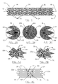
- Figs. 3A through 3C are detailed views illustrating the construction of the prosthesis of Fig. 1.
- Figs. 4A through C schematically illustrate the interaction between adjacent ring frames during compression or expansion of the prosthesis of Fig. 1.
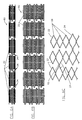
- Figs. 5A through C illustrate a single ring frame, a flat pattern of a ring frame, and a detail of the expanded diamond-shaped elements of a ring frame of the prosthesis of Fig. 1.
- Figs. 6A through C illustrate an axially continuous prosthetic frame having multiple interconnected ring frames in a side view, a flat pattern view, and an expanded detailed view.
- Fig. 7 illustrates a precursor for a ring frame of the prosthesis of Fig. 1 formed as a flat continuous series of diamond-shaped elements.
- Figs. 8A and B illustrate a method for everting the flat structure of Fig. 7 so as to produce a ring frame.
- Fig. 9 illustrates a first method for fabricating the flat structure of Fig. 7.
- Figs. 10A and B illustrate an alternative method for fabricating the flat structure of Fig. 7.
- Fig. 11 schematically illustrates differences in the frame structure between the alternating large and small diamond-shaped elements to minimize the cross-section of the compressed prosthesis and a frame having uniform expandable elements.
-
- Referring now to Fig. 1, an endoluminal stent-
graft 10 generally comprises a tubular structure having aproximal end 12, adistal end 14, and anaxis 16 therebetween. Stent-graft 10 includes aliner 18 supported by aframe 20, the frame here defined by an axial series of independent ring frames 22 affixed toinner liner 18. Each of ring frames 22 is formed as a circumferential series of alternating large diamond-shapedelements 24 and small diamond-shapedelements 26. In the embodiment illustrated in Fig. 1,frame 20 is disposed outside of atubular liner 18 so as to provide a smooth prosthetic lumen. Optionally, a surface of the liner may be disposed over the ring frames, either instead ofinner liner 18 or in combination therewith. - To secure ring frames 22 to
liner 18, the liner is typically sutured to the frame. A wide variety of alternative liner/frame attachment mechanisms are available, including adhesive bonding, heat welding, ultrasonic welding, weaving or braiding the frame elements into the liner, and the like. -
Prosthesis 10 will typically have a length in a range from about 20 mm to about 500 mm, the length preferably being in a range from about 50 mm to about 200 mm, the length of the single lumen stent-graft illustrated ideally being in range from about 59 mm to about 120 mm. A relaxed diameter ofprosthesis 10 will generally be in a range from about 7 mm to about 44 mm, the diameters ideally being in range from about 12 mm to about 32 mm. The number of ring frames 22 used to supportliner 18 ofprosthesis 10 will vary with both the length and diameter of the prosthesis, the number of ring frames typically being in a range from about 4 to about 25, and ideally being in a range from about 5 to about 12. These sizes and ranges are particularly suitable for treatment of aneurysms, including aortic aneurysms. - While the invention can be clearly understood with reference to the straight
tubular prosthesis 10 of Fig. 1, it should be understood that the staggered ring frame of the present invention will also provide advantages for more complex prosthetic systems, including bifurcated prostheses, prosthetic systems having multiple modules for assembly in situ, and the like. Similarly, while these structures will generally be described with reference to prosthetic frames having circumferentially continuous ring frames, it should be understood that the inventions also encompasses frames formed with helical or wound expansible elements. As used herein, the term "loop" encompasses both ring frames and the windings of such helical frames. -
Liner 18 will typically comprise a flexible polymer membrane. Suitable liners may be formed as a continuous woven tube of a polyester such as Dacron™, or the like. Liners may alternatively be formed from braided polyester or other fibers, from a porous polytetrafluorethylene such as Teflon™, or other biocompatible materials.Liner 18 may be substantially inexpansible, or may alternatively expand either resiliently or plastically.Liner 18 will preferably comprise a sufficiently porous material to accommodate cellular in-growth, but will not have pores of a sufficient size to allow the cells to proliferate into and occlude the lumen of the prosthesis. - While
frame 20 will generally be resilient, the present invention will also have advantages when used with plastically deformable prosthetic structures. Suitable biocompatible deformable structures may be formed from a wide variety of metals or polymers, typically comprising platinum, stainless steel, or the like. For such plastically deformable structures, the invention will enhance the structural integrity and strength of the expanded prosthetic frame which can be delivered with a delivery system having a given cross-section. Stated differently, the invention will allow the use of smaller prosthetic devices and delivery systems providing a desired structural strength. Nonetheless, the present invention will find its most immediate applications with resiliently expansible prostheses, as it will generally allow the compression of these prostheses into smaller in diameter delivery catheters. These smaller delivery systems will often have greater axial flexibility than known delivery catheters, and by avoiding radial overlap between adjacent ring frames, the axial flexibility of the prosthesis within the delivery system is also improved. - Referring now to Fig. 2, an
exemplary delivery system 30 comprises atubular sheath 32 and ashaft 34.Sheath 32 has alumen 36 extending from aproximal end 38 to adistal end 40.Shaft 34 is slidably received withinlumen 36, and a plurality ofrunners 42 extend distally from the shaft.Runners 42 line a portion of the inner surface oflumen 36, and slide within the lumen of the shaft.Shaft 34 also has a lumen, in which acoreshaft 44 is affixed so as to provide aguidewire lumen 46.Nose cone 48 is affixed to the distal end ofcoreshaft 44. -
Prosthesis 10 is radially compressed and restrained withinrunners 42. In turn,sheath 32 preventsrunners 42 from expanding outwardly.Runners 42 are formed from a hard material and distribute the expansile load from the frame ofprosthesis 10 over the inner surface oflumen 36. Thehousing 50 at theproximal end 38 ofsheath 32 contains an actuation mechanism for withdrawingsheath 32 proximally whileprosthesis 10 remains axially restrained byrunners 42. More specifically, to withdrawsheath 32 proximally, ahandle 52 is rotated about the axis of the sheath, as illustrated. - An
outer tube 54 extends fromhousing 50, whileshaft 34 extends throughhousing 50 and is affixed to aconnector 56.Connector 56 releasably attachesshaft 34 to the proximal end ofhousing 50, so thatshaft 34 andouter tube 54 can be affixed relative to each other whilesheath 32 is withdrawn to deploy the prosthesis. Hence, the delivery system can be stabilized usingouter tube 54, for example, by inserting the outer tube into a sealing member of an introducer valve. The use and structure ofdelivery system 50 is more fully described in co-pending U.S. Application Serial No. filed January 6, 1999 (Attorney Docket No. 16380-0103 10), the full disclosure of which is incorporated herein by reference. - A distal portion of an alternative delivery system 30' is illustrated in Figs. 2A and B. Beginning at the distal end, nosecone 48' here comprises a polymer such as Pebax™, Hytrel™ or the like, and is preferably injection molded. The contrast of nosecone 48' under fluoroscopy can be enhanced by including a high contrast material such as between about 10 and 40% barium sulfate, depending on the size of the nosecone.
-
Coreshaft 44 may comprise a polymer such as a polyimide. Attachment of the coreshaft and nosecone is preferably provided by buckling a distal portion of the coreshaft and overmolding the nosecone onto the buckled portion, as illustrated in Fig. 2B. - Rather than holding the prosthesis within runners, a
piston 35 engages a proximal end of the prosthesis to hold the prosthesis whilesheath 32 is withdrawn proximally.Piston 35 may comprise a high strength radiopaque material such as a stainless steel, and may be fittingly received within the lumen of thesheath 32.Piston 35 can be heated to melt and affixshaft 34 to the piston where the shaft comprises PEEK.Sheath 32 preferably also comprises PEEK, and should be 13 Fr or smaller for deployment of an iliac prosthetic module. - Referring now to Fig. 3A, sutures 60
affix liner 18 alongproximal end 12 as defined byring frame 22 so as to substantially seal the liner of the prosthesis against the surrounding vascular wall.Sutures 60 also affixposition indicating markers 62, as more fully described in published PCT Patent Application No. WO 97/37616, (Attorney Docket No. 16380-005600PC), the full disclosure of which incorporated herein by reference.Sutures 60 affix the frame and marker structures to the adjacent liner. - Referring now to Fig. 3B, large diamond-shaped
elements 24 of adjacent first andsecond ring frames apices 64 defined by large diamond-shapedelements 24 are held in close proximity by stitching 60.Stitching 60 will typically comprise a suture material such as polyester, but may alternatively comprise a wide variety of biocompatible polymers. In some embodiments, stitching 60 may be replaced by alternative mechanisms for attachment of ring frames 22 toliner 18, as described hereinabove. - Fig. 3C illustrates
liner 18,ring frame 22, andstitching 60 adjacentdistal end 14, and also shows the optional use of an alternativeradiopaque marker 66 which can help to differentiate the ends of the prosthesis when viewing the prosthesis under a fluoroscope, ultrasound, or some other medical imaging modality. Alternatively, similar markers may be used at both ends. A slightly enhanced separation between a ring frame at the end of the prosthesis (preferably the last-compressed end when the prosthesis is loaded into the delivery system) and the adjacent ring frames accommodates some axial displacement of the ring frames during compression and/or deployment. - The structure and use of the specific stitches used to attach ring frames 22 to
liner 18adjacent apices 64 can be understood with reference to Figs. 4A through C.A connector stitch 68 extends over structural elements of first andsecond ring frames adjacent apices 64 when the prosthesis is in the large profile configuration, as can be seen in Figs. 3B and 4A.Associated slider loops 70 extend over the lower and upper arms of first andsecond ring frames liner 18 separated fromapices 64. - As can be understood with reference to Figs. 4B and C, each apex 64 extends farther from the center line of the associated
ring frame 22 whenprosthesis 10 is radially compressed. This elongation of the diamond-shaped elements is caused by the reorientation of the structural elements of the "diamonds:" the four frame elements defining each diamond are more and more aligned with the axis of the prosthesis when the prosthesis is compressed, rather than angling axially and circumferentially. As a result,apices 64 advance axially towards each other. At the same time, the structural arms defining each apex move radially towards each other. Asfirst ring frame 22a is attached toliner 18 byslider stitch 70 along its lower arm, and assecond ring frame 22b is attached toliner 18 by a slider loop over its upper arm, the first ring frame will tend to rotate downward relative to the second ring frame asprosthesis 10 compresses. This relative rotation may be further encouraged by the sliding of the apices against each other as they advance axially. Regardless,apices 64 of large diamond-shapedelements 24 conveniently extend axially between the large diamond-shaped elements of the adjacent ring frame, as illustrated in Fig. 4C. In this embodiment, the compressed large diamond-shapedelements 24 end up axially aligned with the compressed small diamond-shapedelements 26. - While the interaction of
apices 64 of first andsecond ring frames prosthesis 10, it should be understood that similar interactions effect relative rotation between the ring frames when the prosthesis expands. More specifically, a resilient prosthesis constrained in the small profile configuration illustrated in Fig. 4C (or a plastically expansible prosthesis prior to deployment) will experience a shortening of both large and small diamond-shapedelements second ring frames elements 24 shorten,apices 64 slide along each other and into alignment under the constraint ofconnector stitch 68. Slider stitches 70 also urge the large diamond-shaped elements into axial alignment. Once aligned, the large diamond-shaped elements help improve column strength ofprosthesis 10 by transmitting forces axially, either by direct engagement betweenapices 64, or by transmission of force throughcoupling stitch 68 and/orliner 18. It should be understood that only the apices of the large diamond-shaped elements will engage each other, so that the axial flexibility of the prosthetic frame will be greater than if all apices of adjacent ring frames were in engagement. -
Frame 20 may comprise a variety of high strength, biocompatible metals or polymers.Frame 20 will preferably comprise a superelastic shape memory alloy such as Eligiloy™, Nitinol™, or the like. The structural elements forming large and small diamond-shapedelements ring frame 22 as formed in the small profile configuration. The ring frame may be formed by selectively removing the tube material so as to define the shape. Advantageously, such a ring frame has no welded or bonded joints which might fail after deployment. Fig. 5B illustrates a flat pattern view of the tubular structure illustrated in Fig. 5A. - When
ring frame 22 comprises a plastically deformable material, it may be loaded on the deployment balloon (or other expansion device) for deployment. Once expanded, large and small diamond-shapedelements ring frame 22 comprises a resilient material, it will often be expanded over a cylindrical mandrel and heat treated so that the ring frame is biased to return its expanded shape. - Referring now to Figs. 6A through C, an axially
continuous frame 80 includes an axial series of ring frames 22 having large diamond-shapedelements 24 interspersed with small diamond-shapedelements 26. However, in this embodiment, apices of selected large diamond-shapedelements 24 of adjacent ring frames are affixed together to defineaxial connector elements 82. As a result, there may be little or no relative rotation between adjacent ring frames during expansion or compression of axiallycontinuous frame 80. Nonetheless, this structure can help prevent jumbling of the expansible elements when the prosthetic frame is compressed in a delivery sheath. - Alternative methods for fabricating ring frames 22 can be understood with reference to Figs. 7 through 10B. Rather than cutting the ring frame from tubing, a precursor form of
ring frame 22 i comprises a substantially flat structure defining large and small diamond-shapedelements Flat precursor 22 i is everted over amandrel 84 to anintermediate configuration 22 ii, and then to a large profile configuration ofring frame 22 as shown in Figs. 8A and B. The flat pattern ring frame is then set to the desired cylindrical shape by heat treatment while mounted onmandrel 84. - Advantageously, flat pattern ring frames may be mass produced as illustrated in Figs. 9, 10A, and 10B. A plurality of flat pattern
ring frame precursors 22 i might be produced by stamping the precursors simultaneously from sheath stock, as can be understood with reference to Fig. 9. Alternatively, arod stock 86 may be cut using, for example, an Electron Discharge Machining ("EDM")wire 88 to define star shapedtube 90.Tube 90 has a cross-section which may be substantially similar to the shape ofring frame precursor 22 i (see Fig. 7), of the flat pattern, a zig-zag as shown in Fig. 10B, in a flat pattern sinusoid, or the like. Regardless, the expansible elements will preferably comprise interspersed largeexpansible elements 92 and smallexpansible elements 94, the large and small elements preferably alternating circumferentially. A large number of ring frame precursor flat patterns may then be formed by cutting cross-sectional slices fromtube 90, as illustrated in Fig. 10B. These flat pattern ring frame precursors, having alternating large and small expansible elements, may then be everted as described above regarding Figs. 8A and B so as to form final ring frame structures. - Referring now to Fig. 11, a flat pattern ring frame having uniform diamond-shaped
elements 96 is illustrated by dash lines for comparison to ringframe 22 having alternating large and small diamond-shapedelements radii 98 and smaller circumferentialinter-diamond connector 100 inring frame 22.
Claims (19)
- An endoluminal prosthesis comprising a tubular frame (20) having a proximal end (12), a distal end (14), and an axis (16) therebetween, the frame (20) radially expansible from a small diameter configuration to a large diameter configuration for deployment within a body lumen, the frame comprising a circumferentially oriented frame loop defining a plurality of short, axially oriented apices and a plurality of long, axially oriented apices, the long apices extending axially beyond the short apices, the long apices circumferentially interspersed with the short apices.
- The prosthesis of claim 1, comprising a plurality of the circumferentially oriented frame loops, the long apices of first and second axially adjacent frame loops being axially aligned so as to enhance column strength of the frame when the frame is in the large diameter configuration.
- The prosthesis of claim 2, wherein the short apices of the first frame loop are aligned with the long apices of the second frame loop when the frame is in the small diameter configuration.
- The prosthesis of claims 2 or 3, wherein the apices are defined by intersections of elongate frame members, and wherein the first and second frame loops are separated by a separation distance which is less than a combined length of the adjacent frame members of the first and second frame loops when the frame is in the small configuration.
- The prosthesis of any one of the claims 2 to 4, wherein short frame members define the short apices and long frame members define the long apices, and wherein the long apices of the first frame loop are disposed circumferentially between the long frame members of the second frame loop when the frame is in the small configuration, the long apices decreasing in axial length when the frame expands radially to the large configuration.
- The prosthesis of any one of the claims 1 to 5, comprising a tubular liner supported by the frame.
- The prosthesis of any one of the claims 2 to 6, wherein the first and second frame loops rotating relative to each other when the frame expands from the small diameter configuration to the large configuration.
- The prosthesis of any one of the claims 2 to 7, comprising stitches fastening the tubular member to the first and second frame loops, the stitches engaging the frame so that the stitches help effect the rotation.
- The prosthesis of any one of the claims 1 to 8, wherein the loops comprise a circumferential series of diamond-shaped frame elements (24), the diamond-shaped elements (24) having circumferentially alternating large and small sizes.
- The prosthesis of any one of the claims 1 to 9, wherein the frame comprises an adjacent circumferentially oriented frame loop coaxially aligned with the loop, at least one long apex of the loop being affixed to an associated long apex of the adjacent loop, at least one long apex of the loop being axially aligned with an associated short apex of the adjacent loop and at least one short apex of the loop being axially aligned with an associated long apex of the adjacent loop.
- The prosthesis of claim 10, wherein the affixed long apices bend and the associated long and short apices do not interfere when the frame flexes axially.
- An endoluminal prosthesis, especially according to any one of the claims 1 to 11, comprising:a first frame loop defining axial and circumferential orientations, the first frame loop including interspersed large and small expandable elements, the large elements being axially longer than the small elements;a second frame loop aligned coaxially with the first frame loop, the second frame loop being circumferentially expandable and including interspersed large and small expandable elements, the large expandable elements being larger than the small expandable elements;
wherein at least one of the large elements of the first frame loop is axially aligned with an associated small element of the second frame loop when the first and second frame loops are in a small profile configuration; and
wherein at least one of the large elements of the first frame loop is axially aligned with an associated large element of the second frame loop when the first and second frame loops are in a large profile configuration. - The prosthesis of claim 12, wherein the large expandable elements of the first frame loop extend axially to apices adjacent the second frame loop, and wherein the apices of the first frame ring are disposed circumferentially between the large elements of the second frame loop when the first and second frame loops are in the small profile configuration.
- The prosthesis of claims 12 or 13, wherein the apices of the first frame loop are axially aligned with apices of the large elements of the second frame loop when the first and second frame loops are in the large profile configuration.
- The prosthesis of any one of the claims 12 to 14, wherein the first and second ring frames are independently attached to a tubular liner so that the first and second frame loops rotate axially relative to each other as the prosthesis expands circumferentially.
- The prosthesis of any one of the claims 12 to 15, wherein axial lengths of the expandable elements decreases as the expandable elements expand circumferentially, and wherein a distance between a circumferential centerline of the first frame loop and a circumferential centerline of the second frame loop remains constant as the endoluminal prosthesis expands from the small configuration to the large configuration.
- A tubular prosthesis for deployment within a blood vessel, especially according to any one of the claims 1 to 16, the prosthesis comprising:a tubular liner defining axial and circumferential orientations;a first ring frame supporting the liner, the first ring frame having an axial end and including interspersed large and small diamond-shaped elements, the large elements defining apices adjacent the end and being axially longer than the small elements;a second ring frame supporting the liner adjacent the axial end of the first ring frame, the second ring frame including interspersed large and small diamond-shaped elements, the large diamond-shaped elements being larger than the small diamond-shaped elements, the apices of the first ring frame being disposed circumferentially between the large diamond-shaped elements of the second ring frame when the prosthesis is in a small profile configuration for insertion into the blood vessel, the apices of the first ring frame being axially aligned with the large diamond-shaped elements of the second ring frame when the first and second ring frames are in a large profile configuration engaging the surrounding blood vessel, the first and second ring frames rotating axially relative to each other as the prosthesis expands.
- A tubular prosthesis for deployment within a blood vessel, especially according to any one of the claims 1 to 17, the prosthesis comprising:a tubular liner defining axial and circumferential orientations;a first ring frame supporting the liner, the first ring frame defining a centerline and having an axial end and including expandable elements, the expandable elements defining an axial length that decreases when the first ring frame expand from a small profile configuration to a large profile configuration;a second ring frame supporting the liner adjacent the axial end of the first ring frame, the second ring frame defining a centerline and including expandable elements, the expandable elements defining an axial length that decreases when the second ring frame expands from a small profile configuration to a large profile configuration, a separation distance between the centerlines of the first and second ring frames remaining substantially constant when the ring frames expand, the expandable elements of the second ring frames rotating into alignment with the expandable elements of the second ring frame when the first and second ring frames expand so as to enhance axial column strength of the expanded prosthesis.
- A method for preparing an endoluminal prosthesis for deployment, the method comprising:affixing a first ring frame to a tubular liner, the first ring frame having circumferentially interspersed small expandable elements and large expandable elements;affixing a second frame ring to the tubular liner axially adjacent the first ring frame so that the second frame ring having circumferentially interspersed small expandable elements and large expandable elements:loading the prosthesis into a delivery catheter in a small configuration with the large expandable elements of the first frame ring circumferentially interspersed with the large expandable elements of the second frame ring.
Priority Applications (1)
| Application Number | Priority Date | Filing Date | Title |
|---|---|---|---|
| DE60031188T DE60031188T3 (en) | 1999-01-14 | 2000-01-12 | Staggered endoluminal stent |
Applications Claiming Priority (2)
| Application Number | Priority Date | Filing Date | Title |
|---|---|---|---|
| US23193999A | 1999-01-14 | 1999-01-14 | |
| US231939 | 1999-01-14 |
Publications (4)
| Publication Number | Publication Date |
|---|---|
| EP1029517A2 true EP1029517A2 (en) | 2000-08-23 |
| EP1029517A3 EP1029517A3 (en) | 2001-08-01 |
| EP1029517B1 EP1029517B1 (en) | 2006-10-11 |
| EP1029517B2 EP1029517B2 (en) | 2011-06-22 |
Family
ID=22871245
Family Applications (1)
| Application Number | Title | Priority Date | Filing Date |
|---|---|---|---|
| EP00100511A Expired - Lifetime EP1029517B2 (en) | 1999-01-14 | 2000-01-12 | Staggered endoluminal stent |
Country Status (4)
| Country | Link |
|---|---|
| US (1) | US6355057B1 (en) |
| EP (1) | EP1029517B2 (en) |
| AT (1) | ATE342013T1 (en) |
| DE (1) | DE60031188T3 (en) |
Cited By (21)
| Publication number | Priority date | Publication date | Assignee | Title |
|---|---|---|---|---|
| DE10050940A1 (en) * | 2000-10-10 | 2002-04-11 | Biotronik Mess & Therapieg | Coronary stent has outer casing with tubular body consisting of annular support sections, arm elements, connecting arms and turning points |
| WO2002030329A2 (en) * | 2000-10-13 | 2002-04-18 | Rex Medical, L.P. | Covered stents with side branch |
| WO2005070338A1 (en) | 2004-01-20 | 2005-08-04 | Cook Incorporated | Multiple stitches for attaching stent to graft |
| DE102004018255A1 (en) * | 2004-04-15 | 2005-11-10 | Universitätsklinikum Schleswig-Holstein | Vessel prosthesis for maintaining the air chamber function of large blood vessel systems, e.g. the aorta, comprises a tube having an inner wall provided with an elastic flexible lining |
| EP1759670A1 (en) * | 2005-09-02 | 2007-03-07 | Medtronic Vascular, Inc. | Endoluminal prosthesis |
| WO2007100716A2 (en) * | 2006-02-27 | 2007-09-07 | William A. Cook Australia Pty. Ltd. | Retention of stents |
| EP1834607A2 (en) | 2006-03-15 | 2007-09-19 | Cordis Corporation | Stent graft device |
| WO2007131798A1 (en) * | 2006-05-17 | 2007-11-22 | Angiomed Gmbh & Co. Medizintechnik Kg | Bend-capable tubular prosthesis |
| US8152842B2 (en) | 2006-08-21 | 2012-04-10 | C. R. Bard, Inc. | Self-expanding stent |
| US8348988B2 (en) | 2004-01-20 | 2013-01-08 | Cook Medical Technologies, LLC | Endoluminal prosthetic device |
| US8475520B2 (en) | 2006-12-06 | 2013-07-02 | C. R. Bard, Inc. | Stenting ring with marker |
| US8500793B2 (en) | 2006-09-07 | 2013-08-06 | C. R. Bard, Inc. | Helical implant having different ends |
| USRE44463E1 (en) | 2000-08-18 | 2013-08-27 | Angiomed Gmbh & Co. Medizintechnik Kg | Implant with attached element and method of making such an implant |
| US8518101B2 (en) | 2007-04-03 | 2013-08-27 | C. R. Bard, Inc. | Bendable stent |
| US8551156B2 (en) | 2006-11-10 | 2013-10-08 | C. R. Bard, Inc. | Stent |
| US8574286B2 (en) | 2006-05-18 | 2013-11-05 | C. R. Bard, Inc. | Bend-capable stent prosthesis |
| US8721709B2 (en) | 2007-09-07 | 2014-05-13 | C. R. Bard, Inc. | Self-expansible stent with radiopaque markers and method of making such a stent |
| CN105012059A (en) * | 2014-08-19 | 2015-11-04 | 东莞天天向上医疗科技有限公司 | Biodegradable drug stent |
| US9254207B2 (en) | 2006-08-29 | 2016-02-09 | C.R. Bard, Inc. | Annular mesh |
| CN106137481A (en) * | 2015-03-25 | 2016-11-23 | 微创神通医疗科技(上海)有限公司 | A kind of intravascular stent |
| WO2017202766A3 (en) * | 2016-05-24 | 2018-01-11 | Cardiomech As | Flexible implants and method of use |
Families Citing this family (60)
| Publication number | Priority date | Publication date | Assignee | Title |
|---|---|---|---|---|
| US7204848B1 (en) | 1995-03-01 | 2007-04-17 | Boston Scientific Scimed, Inc. | Longitudinally flexible expandable stent |
| EP0884029B1 (en) | 1997-06-13 | 2004-12-22 | Gary J. Becker | Expandable intraluminal endoprosthesis |
| ES2290995T3 (en) * | 1997-09-24 | 2008-02-16 | Med Institute, Inc. | RADIALLY EXPANDABLE ENDOPROTESIS. |
| US6656215B1 (en) * | 2000-11-16 | 2003-12-02 | Cordis Corporation | Stent graft having an improved means for attaching a stent to a graft |
| US6193744B1 (en) * | 1998-09-10 | 2001-02-27 | Scimed Life Systems, Inc. | Stent configurations |
| US20030150821A1 (en) * | 1999-07-16 | 2003-08-14 | Bates Mark C. | Emboli filtration system and methods of use |
| US20030070676A1 (en) * | 1999-08-05 | 2003-04-17 | Cooper Joel D. | Conduits having distal cage structure for maintaining collateral channels in tissue and related methods |
| US20020049490A1 (en) * | 2000-04-11 | 2002-04-25 | Pollock David T. | Single-piece endoprosthesis with high expansion ratios |
| US7229472B2 (en) * | 2000-11-16 | 2007-06-12 | Cordis Corporation | Thoracic aneurysm repair prosthesis and system |
| US6942692B2 (en) * | 2000-11-16 | 2005-09-13 | Cordis Corporation | Supra-renal prosthesis and renal artery bypass |
| US6602283B2 (en) * | 2001-04-06 | 2003-08-05 | Scimed Life Systems, Inc. | Stent design |
| US20050137611A1 (en) * | 2001-09-04 | 2005-06-23 | Broncus Technologies, Inc. | Methods and devices for maintaining surgically created channels in a body organ |
| US7708712B2 (en) * | 2001-09-04 | 2010-05-04 | Broncus Technologies, Inc. | Methods and devices for maintaining patency of surgically created channels in a body organ |
| US20030176914A1 (en) * | 2003-01-21 | 2003-09-18 | Rabkin Dmitry J. | Multi-segment modular stent and methods for manufacturing stents |
| EP1917931A3 (en) | 2001-12-03 | 2013-02-27 | Intek Technology LLC | Multi-segment modular stent and methods for manufacturing stents |
| US20110306997A9 (en) * | 2002-02-21 | 2011-12-15 | Roschak Edmund J | Devices for creating passages and sensing for blood vessels |
| WO2003088820A2 (en) * | 2002-04-19 | 2003-10-30 | Broncus Technologies, Inc. | Devices for maintaining surgically created openings |
| US7223283B2 (en) * | 2002-10-09 | 2007-05-29 | Boston Scientific Scimed, Inc. | Stent with improved flexibility |
| US6849084B2 (en) * | 2002-12-31 | 2005-02-01 | Intek Technology L.L.C. | Stent delivery system |
| US8308682B2 (en) | 2003-07-18 | 2012-11-13 | Broncus Medical Inc. | Devices for maintaining patency of surgically created channels in tissue |
| US20050149168A1 (en) * | 2003-12-30 | 2005-07-07 | Daniel Gregorich | Stent to be deployed on a bend |
| US8409167B2 (en) | 2004-07-19 | 2013-04-02 | Broncus Medical Inc | Devices for delivering substances through an extra-anatomic opening created in an airway |
| CA2608160C (en) | 2005-05-09 | 2013-12-03 | Jurgen Dorn | Implant delivery device |
| JP5061181B2 (en) * | 2006-04-07 | 2012-10-31 | ピナンブラ、インク | System and method for occluding an aneurysm |
| US8512392B2 (en) * | 2007-03-09 | 2013-08-20 | Boston Scientific Scimed, Inc. | Stent design with struts of various angles and stiffness |
| US20090082803A1 (en) * | 2007-09-26 | 2009-03-26 | Aga Medical Corporation | Braided vascular devices having no end clamps |
| US9402707B2 (en) | 2008-07-22 | 2016-08-02 | Neuravi Limited | Clot capture systems and associated methods |
| US9463036B2 (en) | 2010-10-22 | 2016-10-11 | Neuravi Limited | Clot engagement and removal system |
| US10617514B2 (en) * | 2010-12-22 | 2020-04-14 | W. L. Gore & Associates, Inc. | Biased endoluminal device |
| EP2658484A1 (en) | 2010-12-30 | 2013-11-06 | Boston Scientific Scimed, Inc. | Multi stage opening stent designs |
| WO2012119037A1 (en) | 2011-03-03 | 2012-09-07 | Boston Scientific Scimed, Inc. | Stent with reduced profile |
| JP2014511247A (en) | 2011-03-03 | 2014-05-15 | ボストン サイエンティフィック サイムド,インコーポレイテッド | Low strain high strength stent |
| US11259824B2 (en) | 2011-03-09 | 2022-03-01 | Neuravi Limited | Clot retrieval device for removing occlusive clot from a blood vessel |
| WO2012120490A2 (en) | 2011-03-09 | 2012-09-13 | Neuravi Limited | A clot retrieval device for removing occlusive clot from a blood vessel |
| US9345532B2 (en) | 2011-05-13 | 2016-05-24 | Broncus Medical Inc. | Methods and devices for ablation of tissue |
| US8709034B2 (en) | 2011-05-13 | 2014-04-29 | Broncus Medical Inc. | Methods and devices for diagnosing, monitoring, or treating medical conditions through an opening through an airway wall |
| WO2013078235A1 (en) | 2011-11-23 | 2013-05-30 | Broncus Medical Inc | Methods and devices for diagnosing, monitoring, or treating medical conditions through an opening through an airway wall |
| DE102012220129B4 (en) | 2012-11-05 | 2022-12-15 | Optimed Medizinische Lnstrumente Gmbh | stent |
| SI2967610T1 (en) * | 2013-03-14 | 2019-07-31 | Neuravi Limited | A clot retrieval device for removing occlusive clot from a blood vessel |
| US9433429B2 (en) | 2013-03-14 | 2016-09-06 | Neuravi Limited | Clot retrieval devices |
| TR201901830T4 (en) | 2013-03-14 | 2019-03-21 | Neuravi Ltd | Devices and methods for the removal of acute blockages from blood vessels. |
| US11253278B2 (en) | 2014-11-26 | 2022-02-22 | Neuravi Limited | Clot retrieval system for removing occlusive clot from a blood vessel |
| JP2017535352A (en) | 2014-11-26 | 2017-11-30 | ニューラヴィ・リミテッド | Clot collection device for removing obstructive clots from blood vessels |
| US10617435B2 (en) | 2014-11-26 | 2020-04-14 | Neuravi Limited | Clot retrieval device for removing clot from a blood vessel |
| MX2019002565A (en) | 2016-09-06 | 2019-09-18 | Neuravi Ltd | A clot retrieval device for removing occlusive clot from a blood vessel. |
| WO2018144387A1 (en) | 2017-01-31 | 2018-08-09 | W. L. Gore & Associates, Inc. | Pre-strained stent elements |
| US10842498B2 (en) | 2018-09-13 | 2020-11-24 | Neuravi Limited | Systems and methods of restoring perfusion to a vessel |
| US11406416B2 (en) | 2018-10-02 | 2022-08-09 | Neuravi Limited | Joint assembly for vasculature obstruction capture device |
| US11712231B2 (en) | 2019-10-29 | 2023-08-01 | Neuravi Limited | Proximal locking assembly design for dual stent mechanical thrombectomy device |
| US11517340B2 (en) | 2019-12-03 | 2022-12-06 | Neuravi Limited | Stentriever devices for removing an occlusive clot from a vessel and methods thereof |
| US11730501B2 (en) | 2020-04-17 | 2023-08-22 | Neuravi Limited | Floating clot retrieval device for removing clots from a blood vessel |
| US11871946B2 (en) | 2020-04-17 | 2024-01-16 | Neuravi Limited | Clot retrieval device for removing clot from a blood vessel |
| US11717308B2 (en) | 2020-04-17 | 2023-08-08 | Neuravi Limited | Clot retrieval device for removing heterogeneous clots from a blood vessel |
| US11737771B2 (en) | 2020-06-18 | 2023-08-29 | Neuravi Limited | Dual channel thrombectomy device |
| US11937836B2 (en) | 2020-06-22 | 2024-03-26 | Neuravi Limited | Clot retrieval system with expandable clot engaging framework |
| US11439418B2 (en) | 2020-06-23 | 2022-09-13 | Neuravi Limited | Clot retrieval device for removing clot from a blood vessel |
| US11395669B2 (en) | 2020-06-23 | 2022-07-26 | Neuravi Limited | Clot retrieval device with flexible collapsible frame |
| US11864781B2 (en) | 2020-09-23 | 2024-01-09 | Neuravi Limited | Rotating frame thrombectomy device |
| US11937837B2 (en) | 2020-12-29 | 2024-03-26 | Neuravi Limited | Fibrin rich / soft clot mechanical thrombectomy device |
| CN114948362A (en) * | 2021-02-16 | 2022-08-30 | 奥林巴斯株式会社 | Support frame |
Citations (1)
| Publication number | Priority date | Publication date | Assignee | Title |
|---|---|---|---|---|
| WO1997027959A1 (en) | 1996-01-30 | 1997-08-07 | Medtronic, Inc. | Articles for and methods of making stents |
Family Cites Families (32)
| Publication number | Priority date | Publication date | Assignee | Title |
|---|---|---|---|---|
| US5133732A (en) † | 1987-10-19 | 1992-07-28 | Medtronic, Inc. | Intravascular stent |
| US5411552A (en) * | 1990-05-18 | 1995-05-02 | Andersen; Henning R. | Valve prothesis for implantation in the body and a catheter for implanting such valve prothesis |
| CA2380683C (en) | 1991-10-28 | 2006-08-08 | Advanced Cardiovascular Systems, Inc. | Expandable stents and method for making same |
| US5683448A (en) | 1992-02-21 | 1997-11-04 | Boston Scientific Technology, Inc. | Intraluminal stent and graft |
| US5354308A (en) * | 1992-05-01 | 1994-10-11 | Beth Israel Hospital Association | Metal wire stent |
| US5609627A (en) | 1994-02-09 | 1997-03-11 | Boston Scientific Technology, Inc. | Method for delivering a bifurcated endoluminal prosthesis |
| US5733303A (en) † | 1994-03-17 | 1998-03-31 | Medinol Ltd. | Flexible expandable stent |
| EP0679372B1 (en) † | 1994-04-25 | 1999-07-28 | Advanced Cardiovascular Systems, Inc. | Radiopaque stent markers |
| DE4418336A1 (en) * | 1994-05-26 | 1995-11-30 | Angiomed Ag | Stent for widening and holding open receptacles |
| US5575816A (en) | 1994-08-12 | 1996-11-19 | Meadox Medicals, Inc. | High strength and high density intraluminal wire stent |
| US5836964A (en) | 1996-10-30 | 1998-11-17 | Medinol Ltd. | Stent fabrication method |
| WO1996021404A1 (en) † | 1995-01-14 | 1996-07-18 | Prograft, Medical, Inc. | Kink-resistant stent-graft |
| US5683449A (en) | 1995-02-24 | 1997-11-04 | Marcade; Jean Paul | Modular bifurcated intraluminal grafts and methods for delivering and assembling same |
| US6193745B1 (en) * | 1995-10-03 | 2001-02-27 | Medtronic, Inc. | Modular intraluminal prosteheses construction and methods |
| US5824042A (en) * | 1996-04-05 | 1998-10-20 | Medtronic, Inc. | Endoluminal prostheses having position indicating markers |
| EP1006938A4 (en) | 1996-04-08 | 2000-07-05 | Iowa India Investments Company | Multiple interconnected stents and method of coating stents |
| NZ331269A (en) * | 1996-04-10 | 2000-01-28 | Advanced Cardiovascular System | Expandable stent, its structural strength varying along its length |
| US6241760B1 (en) † | 1996-04-26 | 2001-06-05 | G. David Jang | Intravascular stent |
| EP0844853B1 (en) | 1996-05-31 | 2003-12-17 | Ave Galway Limited | Bifurcated endovascular stents |
| US5697971A (en) | 1996-06-11 | 1997-12-16 | Fischell; Robert E. | Multi-cell stent with cells having differing characteristics |
| FR2750853B1 (en) * | 1996-07-10 | 1998-12-18 | Braun Celsa Sa | MEDICAL PROSTHESIS, IN PARTICULAR FOR ANEVRISMS, WITH PERFECTIONED CONNECTION BETWEEN ITS SHEATH AND ITS STRUCTURE |
| US6174326B1 (en) | 1996-09-25 | 2001-01-16 | Terumo Kabushiki Kaisha | Radiopaque, antithrombogenic stent and method for its production |
| DE19653720A1 (en) † | 1996-12-10 | 1998-06-18 | Biotronik Mess & Therapieg | Stent |
| US5827321A (en) | 1997-02-07 | 1998-10-27 | Cornerstone Devices, Inc. | Non-Foreshortening intraluminal prosthesis |
| US6162245A (en) * | 1997-05-07 | 2000-12-19 | Iowa-India Investments Company Limited | Stent valve and stent graft |
| US5843175A (en) | 1997-06-13 | 1998-12-01 | Global Therapeutics, Inc. | Enhanced flexibility surgical stent |
| EP0884029B1 (en) † | 1997-06-13 | 2004-12-22 | Gary J. Becker | Expandable intraluminal endoprosthesis |
| US5824059A (en) | 1997-08-05 | 1998-10-20 | Wijay; Bandula | Flexible stent |
| DE29716117U1 (en) | 1997-09-09 | 1999-01-14 | Micro Science Medical Ag | Stent |
| US6330884B1 (en) † | 1997-11-14 | 2001-12-18 | Transvascular, Inc. | Deformable scaffolding multicellular stent |
| US6132461A (en) * | 1998-03-27 | 2000-10-17 | Intratherapeutics, Inc. | Stent with dual support structure |
| ATE376401T1 (en) † | 1998-11-20 | 2007-11-15 | Boston Scient Ltd | LONGITUDONLY FLEXIBLE AND EXPANDABLE STENT |
-
1999
- 1999-04-06 US US09/287,143 patent/US6355057B1/en not_active Expired - Lifetime
-
2000
- 2000-01-12 AT AT00100511T patent/ATE342013T1/en not_active IP Right Cessation
- 2000-01-12 DE DE60031188T patent/DE60031188T3/en not_active Expired - Lifetime
- 2000-01-12 EP EP00100511A patent/EP1029517B2/en not_active Expired - Lifetime
Patent Citations (1)
| Publication number | Priority date | Publication date | Assignee | Title |
|---|---|---|---|---|
| WO1997027959A1 (en) | 1996-01-30 | 1997-08-07 | Medtronic, Inc. | Articles for and methods of making stents |
Cited By (52)
| Publication number | Priority date | Publication date | Assignee | Title |
|---|---|---|---|---|
| US8900290B2 (en) | 2000-08-17 | 2014-12-02 | Angiomed Gmbh & Co. Medizintechnik Kg | Implant with attached element and method of making such an implant |
| US9480587B2 (en) | 2000-08-17 | 2016-11-01 | Angiomed Gmbh & Co. Medizintechnik Kg | Implant with attached element and method of making such an implant |
| US10213327B2 (en) | 2000-08-17 | 2019-02-26 | Angiomed Gmbh & Co. Medizintechnik Kg | Implant with attached element and method of making such an implant |
| USRE44463E1 (en) | 2000-08-18 | 2013-08-27 | Angiomed Gmbh & Co. Medizintechnik Kg | Implant with attached element and method of making such an implant |
| US6796998B2 (en) | 2000-10-10 | 2004-09-28 | Biotronik Mess- Und Therapiegeraete Gmbh & Co. Ingenieurbuero | Stent |
| DE10050940A1 (en) * | 2000-10-10 | 2002-04-11 | Biotronik Mess & Therapieg | Coronary stent has outer casing with tubular body consisting of annular support sections, arm elements, connecting arms and turning points |
| WO2002030329A2 (en) * | 2000-10-13 | 2002-04-18 | Rex Medical, L.P. | Covered stents with side branch |
| WO2002030329A3 (en) * | 2000-10-13 | 2003-04-24 | Rex Medical Lp | Covered stents with side branch |
| US6890349B2 (en) | 2000-10-13 | 2005-05-10 | Rex Medical, L.P. | Covered stent with side branch |
| JP2007518538A (en) * | 2004-01-20 | 2007-07-12 | クック・インコーポレイテッド | Multiple seams for attaching the stent to the graft |
| US8348988B2 (en) | 2004-01-20 | 2013-01-08 | Cook Medical Technologies, LLC | Endoluminal prosthetic device |
| WO2005070338A1 (en) | 2004-01-20 | 2005-08-04 | Cook Incorporated | Multiple stitches for attaching stent to graft |
| JP4887159B2 (en) * | 2004-01-20 | 2012-02-29 | クック・インコーポレイテッド | Intracavity prosthetic device and method of forming the same |
| JP2011218230A (en) * | 2004-01-20 | 2011-11-04 | Cook Inc | Endoluminal prosthetic device |
| AU2005206200B2 (en) * | 2004-01-20 | 2010-12-09 | Cook Medical Technologies Llc | Multiple stitches for attaching stent to graft |
| DE102004018255A1 (en) * | 2004-04-15 | 2005-11-10 | Universitätsklinikum Schleswig-Holstein | Vessel prosthesis for maintaining the air chamber function of large blood vessel systems, e.g. the aorta, comprises a tube having an inner wall provided with an elastic flexible lining |
| EP1759670A1 (en) * | 2005-09-02 | 2007-03-07 | Medtronic Vascular, Inc. | Endoluminal prosthesis |
| EP1759669A1 (en) * | 2005-09-02 | 2007-03-07 | Medtronic Vascular, Inc. | Endoluminal prosthesis |
| US8663307B2 (en) | 2005-09-02 | 2014-03-04 | Medtronic Vascular, Inc. | Endoluminal prosthesis |
| US8702787B2 (en) | 2005-09-02 | 2014-04-22 | Medtronic Vascular, Inc. | Endoluminal prosthesis |
| WO2007100716A3 (en) * | 2006-02-27 | 2008-02-07 | Cook William A Australia | Retention of stents |
| US7909863B2 (en) | 2006-02-27 | 2011-03-22 | Cook Incorporated | Retention of exposed stent loops |
| WO2007100716A2 (en) * | 2006-02-27 | 2007-09-07 | William A. Cook Australia Pty. Ltd. | Retention of stents |
| EP1834607A3 (en) * | 2006-03-15 | 2007-11-07 | Cordis Corporation | Stent graft device |
| US8690937B2 (en) | 2006-03-15 | 2014-04-08 | Cordis Corporation | Stent graft device |
| US8357194B2 (en) | 2006-03-15 | 2013-01-22 | Cordis Corporation | Stent graft device |
| JP2007244870A (en) * | 2006-03-15 | 2007-09-27 | Cordis Corp | Stent graft device |
| EP1834607A2 (en) | 2006-03-15 | 2007-09-19 | Cordis Corporation | Stent graft device |
| US10849770B2 (en) | 2006-05-17 | 2020-12-01 | C. R. Bard, Inc. | Bend-capable tubular prosthesis |
| US9155642B2 (en) | 2006-05-17 | 2015-10-13 | C.R. Bard, Inc. | Bend-capable tubular prosthesis |
| US8403978B2 (en) | 2006-05-17 | 2013-03-26 | C. R. Bard, Inc. | Bend-capable tubular prosthesis |
| JP4827965B2 (en) * | 2006-05-17 | 2011-11-30 | アンジオメト・ゲーエムベーハー・ウント・コンパニー・メディツィンテクニク・カーゲー | Bendable tubular prosthesis |
| WO2007131798A1 (en) * | 2006-05-17 | 2007-11-22 | Angiomed Gmbh & Co. Medizintechnik Kg | Bend-capable tubular prosthesis |
| US8574286B2 (en) | 2006-05-18 | 2013-11-05 | C. R. Bard, Inc. | Bend-capable stent prosthesis |
| US10231854B2 (en) | 2006-05-18 | 2019-03-19 | C. R. Bard, Inc. | Bend-capable stent prosthesis |
| US9364353B2 (en) | 2006-05-18 | 2016-06-14 | C.R. Bard, Inc. | Bend-capable stent prosthesis |
| US8152842B2 (en) | 2006-08-21 | 2012-04-10 | C. R. Bard, Inc. | Self-expanding stent |
| US9254207B2 (en) | 2006-08-29 | 2016-02-09 | C.R. Bard, Inc. | Annular mesh |
| US8500793B2 (en) | 2006-09-07 | 2013-08-06 | C. R. Bard, Inc. | Helical implant having different ends |
| US9084691B2 (en) | 2006-11-10 | 2015-07-21 | C. R. Bard, Inc. | Stent |
| US10500075B2 (en) | 2006-11-10 | 2019-12-10 | C. R. Bard, Inc. | Stent |
| US8551156B2 (en) | 2006-11-10 | 2013-10-08 | C. R. Bard, Inc. | Stent |
| US8475520B2 (en) | 2006-12-06 | 2013-07-02 | C. R. Bard, Inc. | Stenting ring with marker |
| US9050203B2 (en) | 2007-04-03 | 2015-06-09 | C. R. Bard, Inc. | Bendable stent |
| US8518101B2 (en) | 2007-04-03 | 2013-08-27 | C. R. Bard, Inc. | Bendable stent |
| US10016291B2 (en) | 2007-09-07 | 2018-07-10 | C. R. Bard, Inc. | Self-expansible stent with radiopaque markers and method of making such a stent |
| US8721709B2 (en) | 2007-09-07 | 2014-05-13 | C. R. Bard, Inc. | Self-expansible stent with radiopaque markers and method of making such a stent |
| CN105012059B (en) * | 2014-08-19 | 2017-02-15 | 东莞天天向上医疗科技有限公司 | Biodegradable drug stent |
| CN105012059A (en) * | 2014-08-19 | 2015-11-04 | 东莞天天向上医疗科技有限公司 | Biodegradable drug stent |
| CN106137481B (en) * | 2015-03-25 | 2018-03-06 | 微创神通医疗科技(上海)有限公司 | A kind of intravascular stent |
| CN106137481A (en) * | 2015-03-25 | 2016-11-23 | 微创神通医疗科技(上海)有限公司 | A kind of intravascular stent |
| WO2017202766A3 (en) * | 2016-05-24 | 2018-01-11 | Cardiomech As | Flexible implants and method of use |
Also Published As
| Publication number | Publication date |
|---|---|
| EP1029517B1 (en) | 2006-10-11 |
| DE60031188T2 (en) | 2007-08-23 |
| EP1029517A3 (en) | 2001-08-01 |
| DE60031188T3 (en) | 2012-02-16 |
| EP1029517B2 (en) | 2011-06-22 |
| DE60031188D1 (en) | 2006-11-23 |
| US6355057B1 (en) | 2002-03-12 |
| ATE342013T1 (en) | 2006-11-15 |
Similar Documents
| Publication | Publication Date | Title |
|---|---|---|
| US6355057B1 (en) | Staggered endoluminal stent | |
| US11786386B2 (en) | Integrated stent repositioning and retrieval loop | |
| US11583421B2 (en) | Stent retrieval system | |
| US5749921A (en) | Apparatus and methods for compression of endoluminal prostheses | |
| US8992591B2 (en) | Delivery system with low longitudinal compressibility | |
| US9549833B2 (en) | Stent delivery, repositioning, and removal system | |
| US8226701B2 (en) | Stent and delivery system for deployment thereof | |
| US6331191B1 (en) | Layered endovascular graft | |
| CA2727000C (en) | Controlled deployable medical device and method of making the same | |
| GB2470083A (en) | Closed loop stent | |
| JPH10328215A (en) | Branched stent implant | |
| CA2571282C (en) | Prosthesis comprising a coiled stent and method of use thereof | |
| US20090259295A1 (en) | Method of Delivering Graft Material Without the Use of a Stent | |
| AU2012200481A1 (en) | Stent graft delivery system and vascular repair device |
Legal Events
| Date | Code | Title | Description |
|---|---|---|---|
| PUAI | Public reference made under article 153(3) epc to a published international application that has entered the european phase |
Free format text: ORIGINAL CODE: 0009012 |
|
| AK | Designated contracting states |
Kind code of ref document: A2 Designated state(s): AT BE CH CY DE DK ES FI FR GB GR IE IT LI LU MC NL PT SE |
|
| AX | Request for extension of the european patent |
Free format text: AL;LT;LV;MK;RO;SI |
|
| PUAL | Search report despatched |
Free format text: ORIGINAL CODE: 0009013 |
|
| AK | Designated contracting states |
Kind code of ref document: A3 Designated state(s): AT BE CH CY DE DK ES FI FR GB GR IE IT LI LU MC NL PT SE |
|
| AX | Request for extension of the european patent |
Free format text: AL;LT;LV;MK;RO;SI |
|
| AKX | Designation fees paid |
Free format text: AT BE CH CY DE DK ES FI FR GB GR IE IT LI LU MC NL PT SE |
|
| 17P | Request for examination filed |
Effective date: 20020130 |
|
| RBV | Designated contracting states (corrected) |
Designated state(s): AT BE CH CY DE DK ES FI FR GB GR IE IT LI LU MC NL PT SE |
|
| 17Q | First examination report despatched |
Effective date: 20040122 |
|
| RAP1 | Party data changed (applicant data changed or rights of an application transferred) |
Owner name: MEDTRONIC INC. |
|
| RAP1 | Party data changed (applicant data changed or rights of an application transferred) |
Owner name: MEDTRONIC, INC. |
|
| GRAP | Despatch of communication of intention to grant a patent |
Free format text: ORIGINAL CODE: EPIDOSNIGR1 |
|
| GRAS | Grant fee paid |
Free format text: ORIGINAL CODE: EPIDOSNIGR3 |
|
| GRAA | (expected) grant |
Free format text: ORIGINAL CODE: 0009210 |
|
| AK | Designated contracting states |
Kind code of ref document: B1 Designated state(s): AT BE CH CY DE DK ES FI FR GB GR IE IT LI LU MC NL PT SE |
|
| PG25 | Lapsed in a contracting state [announced via postgrant information from national office to epo] |
Ref country code: CH Free format text: LAPSE BECAUSE OF FAILURE TO SUBMIT A TRANSLATION OF THE DESCRIPTION OR TO PAY THE FEE WITHIN THE PRESCRIBED TIME-LIMIT Effective date: 20061011 Ref country code: BE Free format text: LAPSE BECAUSE OF FAILURE TO SUBMIT A TRANSLATION OF THE DESCRIPTION OR TO PAY THE FEE WITHIN THE PRESCRIBED TIME-LIMIT Effective date: 20061011 Ref country code: FI Free format text: LAPSE BECAUSE OF FAILURE TO SUBMIT A TRANSLATION OF THE DESCRIPTION OR TO PAY THE FEE WITHIN THE PRESCRIBED TIME-LIMIT Effective date: 20061011 Ref country code: NL Free format text: LAPSE BECAUSE OF FAILURE TO SUBMIT A TRANSLATION OF THE DESCRIPTION OR TO PAY THE FEE WITHIN THE PRESCRIBED TIME-LIMIT Effective date: 20061011 Ref country code: LI Free format text: LAPSE BECAUSE OF FAILURE TO SUBMIT A TRANSLATION OF THE DESCRIPTION OR TO PAY THE FEE WITHIN THE PRESCRIBED TIME-LIMIT Effective date: 20061011 Ref country code: AT Free format text: LAPSE BECAUSE OF FAILURE TO SUBMIT A TRANSLATION OF THE DESCRIPTION OR TO PAY THE FEE WITHIN THE PRESCRIBED TIME-LIMIT Effective date: 20061011 |
|
| REG | Reference to a national code |
Ref country code: GB Ref legal event code: FG4D |
|
| REG | Reference to a national code |
Ref country code: CH Ref legal event code: EP |
|
| REG | Reference to a national code |
Ref country code: IE Ref legal event code: FG4D |
|
| REF | Corresponds to: |
Ref document number: 60031188 Country of ref document: DE Date of ref document: 20061123 Kind code of ref document: P |
|
| PG25 | Lapsed in a contracting state [announced via postgrant information from national office to epo] |
Ref country code: DK Free format text: LAPSE BECAUSE OF FAILURE TO SUBMIT A TRANSLATION OF THE DESCRIPTION OR TO PAY THE FEE WITHIN THE PRESCRIBED TIME-LIMIT Effective date: 20070111 Ref country code: SE Free format text: LAPSE BECAUSE OF FAILURE TO SUBMIT A TRANSLATION OF THE DESCRIPTION OR TO PAY THE FEE WITHIN THE PRESCRIBED TIME-LIMIT Effective date: 20070111 |
|
| PG25 | Lapsed in a contracting state [announced via postgrant information from national office to epo] |
Ref country code: ES Free format text: LAPSE BECAUSE OF FAILURE TO SUBMIT A TRANSLATION OF THE DESCRIPTION OR TO PAY THE FEE WITHIN THE PRESCRIBED TIME-LIMIT Effective date: 20070122 |
|
| PG25 | Lapsed in a contracting state [announced via postgrant information from national office to epo] |
Ref country code: MC Free format text: LAPSE BECAUSE OF NON-PAYMENT OF DUE FEES Effective date: 20070131 |
|
| PG25 | Lapsed in a contracting state [announced via postgrant information from national office to epo] |
Ref country code: PT Free format text: LAPSE BECAUSE OF FAILURE TO SUBMIT A TRANSLATION OF THE DESCRIPTION OR TO PAY THE FEE WITHIN THE PRESCRIBED TIME-LIMIT Effective date: 20070319 |
|
| NLV1 | Nl: lapsed or annulled due to failure to fulfill the requirements of art. 29p and 29m of the patents act | ||
| ET | Fr: translation filed | ||
| REG | Reference to a national code |
Ref country code: CH Ref legal event code: PL |
|
| PLBI | Opposition filed |
Free format text: ORIGINAL CODE: 0009260 |
|
| PLAX | Notice of opposition and request to file observation + time limit sent |
Free format text: ORIGINAL CODE: EPIDOSNOBS2 |
|
| 26 | Opposition filed |
Opponent name: TERUMO KABUSHIKI KAISHA Effective date: 20070709 |
|
| PLBB | Reply of patent proprietor to notice(s) of opposition received |
Free format text: ORIGINAL CODE: EPIDOSNOBS3 |
|
| PG25 | Lapsed in a contracting state [announced via postgrant information from national office to epo] |
Ref country code: GR Free format text: LAPSE BECAUSE OF FAILURE TO SUBMIT A TRANSLATION OF THE DESCRIPTION OR TO PAY THE FEE WITHIN THE PRESCRIBED TIME-LIMIT Effective date: 20070112 |
|
| PGFP | Annual fee paid to national office [announced via postgrant information from national office to epo] |
Ref country code: GB Payment date: 20071212 Year of fee payment: 9 |
|
| PGFP | Annual fee paid to national office [announced via postgrant information from national office to epo] |
Ref country code: IT Payment date: 20080118 Year of fee payment: 9 |
|
| PG25 | Lapsed in a contracting state [announced via postgrant information from national office to epo] |
Ref country code: LU Free format text: LAPSE BECAUSE OF NON-PAYMENT OF DUE FEES Effective date: 20070112 Ref country code: CY Free format text: LAPSE BECAUSE OF FAILURE TO SUBMIT A TRANSLATION OF THE DESCRIPTION OR TO PAY THE FEE WITHIN THE PRESCRIBED TIME-LIMIT Effective date: 20061011 |
|
| GBPC | Gb: european patent ceased through non-payment of renewal fee |
Effective date: 20090112 |
|
| PG25 | Lapsed in a contracting state [announced via postgrant information from national office to epo] |
Ref country code: GB Free format text: LAPSE BECAUSE OF NON-PAYMENT OF DUE FEES Effective date: 20090112 |
|
| PG25 | Lapsed in a contracting state [announced via postgrant information from national office to epo] |
Ref country code: IT Free format text: LAPSE BECAUSE OF NON-PAYMENT OF DUE FEES Effective date: 20090112 |
|
| PUAH | Patent maintained in amended form |
Free format text: ORIGINAL CODE: 0009272 |
|
| STAA | Information on the status of an ep patent application or granted ep patent |
Free format text: STATUS: PATENT MAINTAINED AS AMENDED |
|
| 27A | Patent maintained in amended form |
Effective date: 20110622 |
|
| AK | Designated contracting states |
Kind code of ref document: B2 Designated state(s): AT BE CH CY DE DK ES FI FR GB GR IE IT LI LU MC NL PT SE |
|
| REG | Reference to a national code |
Ref country code: DE Ref legal event code: R102 Ref document number: 60031188 Country of ref document: DE Effective date: 20110622 |
|
| REG | Reference to a national code |
Ref country code: FR Ref legal event code: PLFP Year of fee payment: 17 |
|
| REG | Reference to a national code |
Ref country code: FR Ref legal event code: PLFP Year of fee payment: 18 |
|
| REG | Reference to a national code |
Ref country code: FR Ref legal event code: PLFP Year of fee payment: 19 |
|
| PGFP | Annual fee paid to national office [announced via postgrant information from national office to epo] |
Ref country code: DE Payment date: 20180129 Year of fee payment: 19 |
|
| PGFP | Annual fee paid to national office [announced via postgrant information from national office to epo] |
Ref country code: IE Payment date: 20180129 Year of fee payment: 19 Ref country code: FR Payment date: 20180125 Year of fee payment: 19 |
|
| REG | Reference to a national code |
Ref country code: DE Ref legal event code: R119 Ref document number: 60031188 Country of ref document: DE |
|
| REG | Reference to a national code |
Ref country code: IE Ref legal event code: MM4A |
|
| PG25 | Lapsed in a contracting state [announced via postgrant information from national office to epo] |
Ref country code: DE Free format text: LAPSE BECAUSE OF NON-PAYMENT OF DUE FEES Effective date: 20190801 Ref country code: FR Free format text: LAPSE BECAUSE OF NON-PAYMENT OF DUE FEES Effective date: 20190131 |
|
| PG25 | Lapsed in a contracting state [announced via postgrant information from national office to epo] |
Ref country code: IE Free format text: LAPSE BECAUSE OF NON-PAYMENT OF DUE FEES Effective date: 20190112 |