EP1029789A2 - Contact lens transfer and material removal system - Google Patents
Contact lens transfer and material removal system Download PDFInfo
- Publication number
- EP1029789A2 EP1029789A2 EP00301264A EP00301264A EP1029789A2 EP 1029789 A2 EP1029789 A2 EP 1029789A2 EP 00301264 A EP00301264 A EP 00301264A EP 00301264 A EP00301264 A EP 00301264A EP 1029789 A2 EP1029789 A2 EP 1029789A2
- Authority
- EP
- European Patent Office
- Prior art keywords
- nozzle
- hood
- vacuum
- lens
- probe
- Prior art date
- Legal status (The legal status is an assumption and is not a legal conclusion. Google has not performed a legal analysis and makes no representation as to the accuracy of the status listed.)
- Granted
Links
Images


Classifications
-
- B—PERFORMING OPERATIONS; TRANSPORTING
- B65—CONVEYING; PACKING; STORING; HANDLING THIN OR FILAMENTARY MATERIAL
- B65G—TRANSPORT OR STORAGE DEVICES, e.g. CONVEYORS FOR LOADING OR TIPPING, SHOP CONVEYOR SYSTEMS OR PNEUMATIC TUBE CONVEYORS
- B65G49/00—Conveying systems characterised by their application for specified purposes not otherwise provided for
- B65G49/05—Conveying systems characterised by their application for specified purposes not otherwise provided for for fragile or damageable materials or articles
-
- B—PERFORMING OPERATIONS; TRANSPORTING
- B65—CONVEYING; PACKING; STORING; HANDLING THIN OR FILAMENTARY MATERIAL
- B65B—MACHINES, APPARATUS OR DEVICES FOR, OR METHODS OF, PACKAGING ARTICLES OR MATERIALS; UNPACKING
- B65B25/00—Packaging other articles presenting special problems
- B65B25/008—Packaging other articles presenting special problems packaging of contact lenses
-
- B—PERFORMING OPERATIONS; TRANSPORTING
- B29—WORKING OF PLASTICS; WORKING OF SUBSTANCES IN A PLASTIC STATE IN GENERAL
- B29D—PRODUCING PARTICULAR ARTICLES FROM PLASTICS OR FROM SUBSTANCES IN A PLASTIC STATE
- B29D11/00—Producing optical elements, e.g. lenses or prisms
- B29D11/00009—Production of simple or compound lenses
- B29D11/00038—Production of contact lenses
- B29D11/00125—Auxiliary operations, e.g. removing oxygen from the mould, conveying moulds from a storage to the production line in an inert atmosphere
- B29D11/0023—Transferring contact lenses
- B29D11/0024—Transferring contact lenses using a vacuum suction gripper
-
- B—PERFORMING OPERATIONS; TRANSPORTING
- B65—CONVEYING; PACKING; STORING; HANDLING THIN OR FILAMENTARY MATERIAL
- B65G—TRANSPORT OR STORAGE DEVICES, e.g. CONVEYORS FOR LOADING OR TIPPING, SHOP CONVEYOR SYSTEMS OR PNEUMATIC TUBE CONVEYORS
- B65G47/00—Article or material-handling devices associated with conveyors; Methods employing such devices
- B65G47/74—Feeding, transfer, or discharging devices of particular kinds or types
- B65G47/90—Devices for picking-up and depositing articles or materials
- B65G47/91—Devices for picking-up and depositing articles or materials incorporating pneumatic, e.g. suction, grippers
Definitions
- the present invention relates to a method and apparatus for transferring wet plastic objects, such as contact lenses, from one station to another.
- each lens is formed by molding a reactive mixture between a front curve (lower mold section) and back curve (upper mold section).
- the lenses are carried in a mold array or pallet, such as a two-by-four array. While in between the front and back curves, the monomer is polymerized to form the lens.
- the lens is removed from the front curve mold during a hydration step and then washed by the application of a hydrating deionized (DI) water to remove processing chemicals, e.g. diluents, from the lens.
- DI hydrating deionized
- the final step of the process is to introduce a buffered saline solution into the final package holding the lens, and then seal the lens within the package so that the final lens equilibrium (ionic neutralization, final hydration and final lens dimensioning) is accomplished in the package at room temperature or during sterilization.
- U.S. Patent No. 4,961,820 also assigned to the assignee of the present invention, discloses a final package for a contact lens, wherein the package is formed from a transparent plastic material such as polypropylene and a foil laminate that is heat sealed thereto.
- the transfer of soft contact lenses during manufacture has been a significant problem.
- the lenses are small, are nearly invisible and are particularly hard to handle when immersed in the fluids commonly used in the manufacturing process. Accurate and reliable transfer of the wet lenses from one location to another or to a final package are often necessary during the manufacturing process.
- U.S. Patent No. 5,578,331 entitled “Automated Apparatus and Method for Preparing Contact Lenses for Inspection and Packaging", also assigned to the assignee of the present invention, discloses a robotic arm for transferring a plurality of soft contact lenses from a first processing station to a second processing station.
- the robotic device includes an adjustable array of convex contact lens carriers.
- the specification of U.S. Patent No. 5,578,331 is herein incorporated by reference.
- U.S. Patent No. 5,561,970 which also is owned by the assignee of this application, discloses an automatic contact lens transfer system, comprising robotic arms to contact and transfer soft contact lenses.
- the '970 patent is hereby incorporated by reference.
- U.S. Patent No. 5,706,634 which also is owned by the assignee of this application, discloses a contact lens transfer device which comprises a convex lens transfer surface onto which the lens is secured via surface tension. The device then transports the lens to a second location. The lens is removed from the convex lens transfer surface when an amount of deionized water is ejected from the device.
- the '634 patent is hereby incorporated by reference.
- neither of these patents teach the removal of the hydrating solution or other matter, nor are they capable of performing the function of transfer and controlled matter removal.
- prior contact lens transfer systems fail to address splatter of liquid from a lens onto the packaging during lens transfer.
- the invention is concerned with the withdrawal of excess or foreign matter from a wet object, such as a contact lens, and/or its packaging prior to being sealed in a package.
- a wet object such as a contact lens
- this is achieved by providing a hood around a probe which is used to pick up and later release the wet object.
- the probe preferably handles the wet object using positive and negative pressure.
- the hood encompassing the probe creates suction to control matter during deposition and matter withdrawal or removal.
- the invention is directed to a method and apparatus for transferring a wet object, such as a contact lens, during and between various steps of manufacture and packaging.
- a wet object such as a contact lens
- One set of these manufacturing steps is disclosed in copending European patent application No. filed concurrently herewith, claiming priority from USSN 09/252 307 (Attorney's ref: P023953EP) in which transfer is necessary from a station at which washing and hydration of the lens takes place, in a front curve mold, to a final package designed for customer use.
- this apparatus could be used to transfer a lens from a reusable mold to a contact lens package, or from a mold to a container for inspection of the contact lens, or from any other first position to a second position.
- the invention comprises a probe with a perforated hemispherical nozzle head having a diameter and shape corresponding to the contact lens shape.
- the probe is moved into close proximity, and more preferably into contact with the lens' concave surface while in a carrier or holder, such as a front curve mold, and picks up the contact lens from the holder by vacuum force, which creates suction at the nozzle which draws the lens from the holder onto the probe hemispherical nozzle.
- a hood assembly encompasses the lower end of the probe and is resiliently biased to exert downward pressure preferably via holding pins on the carrier or holder, e.g., front curve, from which the lens is being removed to hold it in place against the vacuum force as the lens is being removed from the front curve mold.
- the probe is then relocated over the carrier or package into which the lens is to be deposited.
- the vacuum is shut off, with the lens being held by surface tension while the probe is relocated over the carrier or package.
- the vacuum force supply can be shut off after the probe has been positioned over the carrier or package.
- the hood is pressed against the carrier or package, holding it in place, and if a package, the hood is designed to protect the sealing area from splashing.
- one or more short, controlled pressure pulses of liquid or gas, preferably air are supplied.
- a vacuum is applied within more than one passage designed within an opening from the hood assembly.
- the contact lens is ejected from the probe into the package by at least one pressure pulse, and any residual washing solution or other material on the lens or packaging which is displaced from the contact lens by the pressure pulse(s) or movement of the lens off the probe is drawn into the passage of the hood by the vacuum.
- the vacuum draws away any excess matter which becomes airborne during the ejecting step, and preferably the vacuum also removes any matter in the heat seal area of the package to provide for successful package closure.
- Presence of the lens during transfer can be detected by measurement of the vacuum that is achieved. A low vacuum indicates that there is no lens carried by the probe.
- the invention provides a method for transferring a wet object from a first position to a second position.
- the method includes the steps of picking up an object from a first position with a nozzle, ejecting the object from the nozzle with a pressurized fluid to a second position, and drawing away any excess matter from the object which becomes airborne during the ejecting step.
- the drawing step commences before the ejecting step with the excess matter being drawn away from and external to the nozzle.
- the method may further include the step of providing a coating material to the object during the transfer process, with excess coating material being drawn away the same as any other excess matter.
- the object being transferred can be relocated to a different position by moving the nozzle after it is picked up, or the object can be relocated by moving a new container, for example, product packaging, under the nozzle while the nozzle remains stationary.
- the method of the invention transfers a wet object from a first container to a second container.
- This process includes the steps of locating a probe having a nozzle adjacent the object in the first container, creating a vacuum in the nozzle to draw the object to the nozzle, deactivating the vacuum, providing a pressurized fluid in the nozzle to release the object and to displace any excess matter from the object, and creating a vacuum within a hood disposed about the nozzle to draw away the any excess matter.
- an apparatus for transferring a wet object from a first station to a second station includes a probe having a reciprocating barrel with a passage for communication with a positively or negatively pressurized fluid.
- a nozzle is affixed at one end of the probe for transferring the wet object from the first station to the second station, the nozzle being in communication with the passage.
- a variety of nozzles of different sizes and shapes can be affixed to the probe.
- a hood is disposed about the nozzle and is connectable to a vacuum source.
- the hood includes spacers which depend therefrom and space the hood from the station that it contacts, for example, a front curve mold for a contact lens or a contact lens package.
- the spacers limit movement of the hood and ensure that an inflow passageway is available to cause air to rush over the station (e.g., the seal area of a package) and thereby dry the area surrounding the hood or maintain that area dry during the transfer of the wet object.
- the apparatus may further include a controller programmed to control the vacuum connection to the hood and the application of pressurized fluid to the probe, and controls the movement of the assembly.
- Another object is to provide a method and apparatus for pickup and transfer of wet flexible molded parts and removing the liquid and other matter, particularly from the surface of the molded parts, during the transfer.
- An additional object is to provide a method and apparatus for transferring a wet object, such as a contact lens, from one station to another which uses a probe to remove the lens from the first station by vacuum pressure and transfer it to the second station where it is deposited by applying a pressurized stream or pulse of air or liquid through the probe to the object.
- a wet object such as a contact lens
- a further object is to provide a probe to transfer a wet lens from one position to another and to remove excess liquid or other matter from the lens surface during the transfer.
- Yet a further object is to provide a method and apparatus for transferring a wet object which prevents contamination of the heat seal area of the package.
- the hood fits over the package to prevent contamination of the heat seal area.
- Another object is to provide a probe which has a hood which prevents the pickup of the containers at the first and second stations.
- the probe 10 has a tubular barrel 12 having a central passage 14 which is controllably connected to sources of a vacuum A and compressed gas C, such as air (see Fig. 4).
- the probe is of any suitable material, for example, a high density , polyetheretherketone (PEEK).
- PEEK polyetheretherketone
- the probe barrel 12 is spring loaded by spring 35.
- the probe barrel 12 is controllably driven by a suitable mechanism, such as a pneumatic or electromagnetic driven piston, to move it laterally and/or to reciprocate it up and down. Once the probe contacts a contact lens, any additional downward movement of the probe causes the spring 35 to compress until the probe assembly is moved back up (reciprocated).
- the probe is preferably resiliently biased when it contacts a contact lens.
- the barrel 12 is surrounded by and slides in a sleeve 31 whose lower enlarged end defines a hood 28, which surrounds the lower end of the barrel 12.
- the barrel 12 and sleeve 31 reciprocate in a stationary
- the hood 28 defines a passage 30 for a vacuum.
- the hood 28 is connected to a vacuum B.
- the hood 28 surrounds the sides of the nozzle 40 attached to the lower end of the probe 10.
- the hood 28 and sleeve 31 are spring loaded by a spring 16 within a casing 17.
- the casing 17 preferably provides equal distribution of the vacuum within the hood and around the probe 10.
- the spring's 16 upper end engages the mounting block 20, and its lower end engages a seat 19 on of the hood 28.
- the hood 28 also moves with it by the action of the spring load provided by spring 16.
- the nozzle 40 at the lower end of the probe barrel 12 is in communication with the central passage 14.
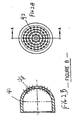
- the nozzle 40 is of generally semi-spherical shape (although other shapes can be provided) and has a plurality of perforations 42, preferably 0.28 mm to 0.41 mm in diameter, and more preferably closer to about 0.41 mm in diameter.
- the nozzle perforations 42 preferably are arranged in concentric rings, as shown in Fig. 2A, over the entire nozzle surface area including having holes which permit the vacuum to engage the edges of the lenses 24 for optimum pick-up.
- the nozzle 40 preferably is of a hard material. It is of a size and shape to generally conform to the object to be transferred, here the inner concave surface of the lens.
- the nozzle may be made interchangeable so as to accommodate objects of different sizes and shapes. Generally the nozzle is about 12 to 15 mm in diameter, depending on the size of the object, e.g. lens, being transferred. Vacuum is achieved or compressed air is supplied through the perforations 42 in the nozzle 40 via the barrel 12 and the central passage 14.
- the hood 28 can be used with the nozzles described in the aforementioned U.S. Patent Nos. 5,561,970 and 5,706,634.
- the probe 10 is to transfer a wet object from a first station to a second station.
- the object is a wet, hydrogel contact lens 52.
- the lens 52 is shown in a concave mold 50, called the front curve in the manufacture of contact lenses.
- the mold 50 can be of plastic or of a reusable mold material, e.g. quartz.
- the mold 50 also can represent a tray or other type of holder to hold the lens while being subjected to a hydration bath or other processing stage.
- the hydration bath also can be carried out while the lens is in the mold.
- the wet lens 52 is to be removed from the mold 50 and transferred to a second station, which in Fig. 1B is a package 60 having a well 62 into which the lens 52 is to be placed, or deposited. This can be the final package which is to be opened by a consumer.
- the package well 62 has a surrounding lip 63 which defines the heat-seal area of the package. Also, before, during and/or after the deposition of the lens into the package well 62, liquid and/or other residual material on the contact lens and/or within the package can be removed in a controlled and repeatable manner by the lens transfer device of this invention.
- the probe barrel 12 is preferably moved in register with the lens 52, and downwardly moved to preferably contact the lens 52, and to slightly compress the spring 35.
- the vacuum is applied through the barrel central passage 14 to pick up the lens from the mold 50 to be engaged against the nozzle 40.
- the pickup vacuum pressure can be in the range of about 0.06 to 0.15 barr, for example.
- the hood 28 is positioned above the front curve mold 50.
- the hood 28 is resiliantly biased by spring 19 against the front curve mold, and pins or spacers 70 on the hood 28 engage the front curve mold 50 to prevent the mold from being picked up by the suction from the nozzle 40 as it picks up the lens 52, and as the barrel 12 with the attached lens 52 is raised by the external mechanism.
- the vacuum(s) within the barrel 12 and/or hood 28 can be used to remove all of the liquid from the first station from which the lens is removed.
- the vacuum assists in preparing such molds for reuse by withdrawing all of the liquid.
- Tween 80 polysorbate 80NF, manufactured by ICI Specialty Chemicals, at 10 to 100 ppm, and preferably 20-30 ppm to the last liquid the contact lens contacts prior to transfer using the nozzle of this invention, may improve lens transfer performance.
- Other surfactants or other processing agents can be added to the liquid.
- the wet lens 52 has now been removed from the first station and is to be deposited into the package well 62. Either the mounting block 20 with the probe 10 is moved over the package 60, or the package is moved under the probe. This is accomplished by any conventional mechanism.
- the nozzle barrel 12 is moved downwardly onto the package 60 and is stopped when the nozzle with the lens and the package are at a fixed distance apart, preferably, defining a gap of 0.3 - 0.7 mm, and more preferably a gap of approximately 0.5 mm between the nozzle and the bottom of the package well 62.
- the lower end of the hood 28 is resiliantly biased against the package positioned by the stop pins or spacers 70, as shown in Fig. 3, which also provides a space between the lower end of the hood and the package lip 63.
- the stop pins 70 fix the distance between the nozzle 40 and the bottom of the package well 62 (Fig. 1B) and the mold 50 (Fig. 1A).
- the vacuum flow in probe passage 14 is stopped, if not stopped earlier.
- compressed gas is then blown, for example, as one or a series of several jets or pulses, through the probe central passage 14.
- the jets or pulses may range in duration from 0.3 to 2.5 seconds, preferably 0.3 to 0.7 seconds, with a 0.5 second off-time therebetween, and may be pulsed one to three times, for example.
- the pressurized pulses can be, for example, 20 lb/in, 1 to 1.5 barr. In and around this time, including shortly before and shortly after, a vacuum is drawn around the perimeter of the probe barrel 12 through the hood 28 within the passage 30.
- the vacuum is drawn in the passage 30 before the vacuum in the passage 14 is stopped, and more preferably, just before the vacuum is stopped, for example, 0.5 second before.
- the vacuum within the passage 30 can be, for example, 0.12 to 0.20 barr.
- the compressed air drives the lens 52 off of the nozzle 40 into the package well 62. It also drives liquid, and any other material, from the lens surface, and the vacuum drawn through the hood passage 30 captures this blown off material.
- the strength of the vacuum in the passage 30, under the hood 28, is greater than that of the jets or pulses conveyed through the nozzle 40 from the passage 14.
- the vacuum in the passage 30 not only draws liquid from the lens 52, it also draws air across the package lip 63 or seal area of the package through the inflow passageways 74 and into the passage 30 to dry or maintain this area dry to better ensure that the package 60 is effectively heat sealed with a lidstock, if this is needed.
- the lens is not drawn into the passage 30, partially due to the in-rush of air or other ambient gas from outside the hood 28 and the package 60 through the inflow passageways 74, and also due to the pulses/stream of positive pressure applied to the lens from the passage 14.
- the well is filled with a buffered solution, such as saline, before the package is sealed.
- the hood 28 has a circumferential size which generally matches the well in the package 60 and the lip 53 round the concave mold 50.
- the stop pins 70 will readily engage the heat-seal area 63 of the package 60 and the lip 53 of the mold 50, yet permit an in-rush of air through the inflow passageways 74 between the pins 70.
- the hood is designed to prevent contamination of the heat-seal area of the package, by making the circumference of the hood substantially match the shape of the heat-seal area of the package.
- the front curve mold 50 can be sucked clear of its contents, the lens 24 transferred, and the mold cleaned (e.g., by injecting mold cleaning solution delivered by the nozzle or other device, with the solution removed simultaneously).
- the vacuum established within the passage 30 and compressed gas pulses from passage 40 can then be used to dry and clean the front curve mold 50 once the lens has been transferred.
- Fig. 4 is a schematic diagram of the air/gas control system for the probe/hood assembly.
- These are two vacuum sources A, and B and one compressed gas source C.
- Vacuum source A and compressed gas source C communicate with the probe central passage 14, either to apply suction or gas pressure.
- Vacuum source B comprises a high-mass regenerative blower 88, which applies a vacuum to the hood 28 through passage 30.
- Vacuum source A is controlled by a two-way valve 80 which regulates the compressed air source 85 feeding the vacuum ejector 86.
- an alternate source of vacuum could be used, e.g. a regenerative blower.
- Compressed gas C is provided by a compressed air source 87 controlled by a two-way valve 81.
- the vacuum in the hood 28 is controlled by a two-way valve 82.
- a Programmable Logic Controller PLC can control each valve and the assembly movement in a properly timed sequence as described previously.
- Two gauges monitor pressures applied to passages 14 and 30 of the probe 10/hood 28 assembly.
- Gauge 83 monitors both pressure and vacuum that is applied to the wet lens 52, preferably supplying feedback to the PLC.
- Gauge 84 monitors vacuum to the hood, preferably supplying feedback to the PLC.
- Gauge 83 has the capability of monitoring the system to determine if a lens 52 is present on the nozzle 40 of the probe.
- the PLC can be programmed in a conventional manner to control and ensure that the process is operating within prescribed parameters and that the valves and vacuum/pressure sources are operating correctly. Operation outside of the range of prescribed parameters can be noted by the PLC to identify one or more lenses 52, molds 50, or trays 20 to be marked for removal.
- a mechanical, electrical or computer operated controller controls valves 80, 81 and 82, as well as an electromagnetic, cam, or pneumatic driver 88 that reciprocates the probe.
- the controller is programmed to perform the operation described above in the properly timed sequence.
- the pressurized fluid can be air, an inert gas, a buffered saline solution or distilled water as a liquid or vapor, and may include a coating material for the surface of the contact lens, for example, a coating material which makes the lens more hydrophilic.
- a coating material for the surface of the contact lens, for example, a coating material which makes the lens more hydrophilic.
- such coating can be added to the lens as an aerosol spray or part of a liquid which emanates from the nozzle 40 with a gas during release of the lens from the probe 10.
- the coating or another additive can be added as part of a separate processing step, for example, after the lens has been placed in the package 60.
- the lens transfer method and apparatus of the invention works effectively over a wide range of lens designs, including monofocal, multifocal, and toric lenses.
- the lens transfer method and apparatus of the invention provide a highly efficient controlled method over previous techniques with the ability to successfully transfer up to and exceeding 99% of the contact lenses.
- the term "excess matter” refers to any foreign matter or material which has not been prescribed or specified for a particular object such as a contact lens or contact lens package.
- "excess matter” in the case of a hydrogel contact lens having a hydrophilic coating includes any water, saline solution, leachable diluent or processing chemical or the like which may be on the lens at a particular stage of processing.
Abstract
Description
- The present invention relates to a method and apparatus for transferring wet plastic objects, such as contact lenses, from one station to another.
- The molding of hydrophilic contact lenses is known. Various processes are disclosed in U.S. Patent No. 4,495,313 to Larsen; U.S. Patent No. 4,640,489 to Larsen, et al.; U.S. Patent No. 4,680,336 to Larsen et al.; U.S. Patent No. 4,889,664 to Larsen et al.; and U.S. Patent No. 5,039,459 to Larsen et al., all of which are assigned to the assignee of the present invention.
- These prior art references disclose a contact lens production process wherein each lens is formed by molding a reactive mixture between a front curve (lower mold section) and back curve (upper mold section). Typically, the lenses are carried in a mold array or pallet, such as a two-by-four array. While in between the front and back curves, the monomer is polymerized to form the lens. In one type of process, the lens is removed from the front curve mold during a hydration step and then washed by the application of a hydrating deionized (DI) water to remove processing chemicals, e.g. diluents, from the lens.
- Sometimes, when deionized water is used in the hydration, the final step of the process is to introduce a buffered saline solution into the final package holding the lens, and then seal the lens within the package so that the final lens equilibrium (ionic neutralization, final hydration and final lens dimensioning) is accomplished in the package at room temperature or during sterilization. U.S. Patent No. 4,961,820, also assigned to the assignee of the present invention, discloses a final package for a contact lens, wherein the package is formed from a transparent plastic material such as polypropylene and a foil laminate that is heat sealed thereto.
- The transfer of soft contact lenses during manufacture has been a significant problem. The lenses are small, are nearly invisible and are particularly hard to handle when immersed in the fluids commonly used in the manufacturing process. Accurate and reliable transfer of the wet lenses from one location to another or to a final package are often necessary during the manufacturing process.
- As apparent from the foregoing, a need exists for an apparatus to transfer wet lenses from one station, such as a mold or hydrating bath, to another station, such as a package, and at the same time to remove or reduce the amount of the hydrating liquid and other material present on the lens from the hydrating process.
- U.S. Patent No. 5,578,331, entitled "Automated Apparatus and Method for Preparing Contact Lenses for Inspection and Packaging", also assigned to the assignee of the present invention, discloses a robotic arm for transferring a plurality of soft contact lenses from a first processing station to a second processing station. The robotic device includes an adjustable array of convex contact lens carriers. The specification of U.S. Patent No. 5,578,331 is herein incorporated by reference.
- U.S. Patent No. 5,561,970, which also is owned by the assignee of this application, discloses an automatic contact lens transfer system, comprising robotic arms to contact and transfer soft contact lenses. The '970 patent is hereby incorporated by reference. U.S. Patent No. 5,706,634, which also is owned by the assignee of this application, discloses a contact lens transfer device which comprises a convex lens transfer surface onto which the lens is secured via surface tension. The device then transports the lens to a second location. The lens is removed from the convex lens transfer surface when an amount of deionized water is ejected from the device. The '634 patent is hereby incorporated by reference. However, neither of these patents teach the removal of the hydrating solution or other matter, nor are they capable of performing the function of transfer and controlled matter removal. In addition, prior contact lens transfer systems fail to address splatter of liquid from a lens onto the packaging during lens transfer.
- The invention is concerned with the withdrawal of excess or foreign matter from a wet object, such as a contact lens, and/or its packaging prior to being sealed in a package. In preferred embodiments, this is achieved by providing a hood around a probe which is used to pick up and later release the wet object. The probe preferably handles the wet object using positive and negative pressure. The hood encompassing the probe creates suction to control matter during deposition and matter withdrawal or removal.
- In one respect, the invention is directed to a method and apparatus for transferring a wet object, such as a contact lens, during and between various steps of manufacture and packaging. One set of these manufacturing steps is disclosed in copending European patent application No. filed concurrently herewith, claiming priority from USSN 09/252 307 (Attorney's ref: P023953EP) in which transfer is necessary from a station at which washing and hydration of the lens takes place, in a front curve mold, to a final package designed for customer use. Alternatively, this apparatus could be used to transfer a lens from a reusable mold to a contact lens package, or from a mold to a container for inspection of the contact lens, or from any other first position to a second position.
- In a preferred embodiment, the invention comprises a probe with a perforated hemispherical nozzle head having a diameter and shape corresponding to the contact lens shape. The probe is moved into close proximity, and more preferably into contact with the lens' concave surface while in a carrier or holder, such as a front curve mold, and picks up the contact lens from the holder by vacuum force, which creates suction at the nozzle which draws the lens from the holder onto the probe hemispherical nozzle.
- A hood assembly encompasses the lower end of the probe and is resiliently biased to exert downward pressure preferably via holding pins on the carrier or holder, e.g., front curve, from which the lens is being removed to hold it in place against the vacuum force as the lens is being removed from the front curve mold.
- The probe is then relocated over the carrier or package into which the lens is to be deposited. In a preferred mode, once the lens is lifted by the probe out of the front curve mold, the vacuum is shut off, with the lens being held by surface tension while the probe is relocated over the carrier or package. Alternatively, the vacuum force supply can be shut off after the probe has been positioned over the carrier or package. Preferably, the hood is pressed against the carrier or package, holding it in place, and if a package, the hood is designed to protect the sealing area from splashing. Once in the proper location, one or more short, controlled pressure pulses of liquid or gas, preferably air, are supplied. At the same time, preferably a vacuum is applied within more than one passage designed within an opening from the hood assembly. As a result, the contact lens is ejected from the probe into the package by at least one pressure pulse, and any residual washing solution or other material on the lens or packaging which is displaced from the contact lens by the pressure pulse(s) or movement of the lens off the probe is drawn into the passage of the hood by the vacuum. This results in rapid placement of the contact lens into the final package without excess matter on the lens or the package. The vacuum draws away any excess matter which becomes airborne during the ejecting step, and preferably the vacuum also removes any matter in the heat seal area of the package to provide for successful package closure.
- Presence of the lens during transfer can be detected by measurement of the vacuum that is achieved. A low vacuum indicates that there is no lens carried by the probe.
- In one respect, the invention provides a method for transferring a wet object from a first position to a second position. The method includes the steps of picking up an object from a first position with a nozzle, ejecting the object from the nozzle with a pressurized fluid to a second position, and drawing away any excess matter from the object which becomes airborne during the ejecting step. In a preferred mode, the drawing step commences before the ejecting step with the excess matter being drawn away from and external to the nozzle. The method may further include the step of providing a coating material to the object during the transfer process, with excess coating material being drawn away the same as any other excess matter. The object being transferred can be relocated to a different position by moving the nozzle after it is picked up, or the object can be relocated by moving a new container, for example, product packaging, under the nozzle while the nozzle remains stationary.
- In another respect, the method of the invention transfers a wet object from a first container to a second container. This process includes the steps of locating a probe having a nozzle adjacent the object in the first container, creating a vacuum in the nozzle to draw the object to the nozzle, deactivating the vacuum, providing a pressurized fluid in the nozzle to release the object and to displace any excess matter from the object, and creating a vacuum within a hood disposed about the nozzle to draw away the any excess matter.
- According to another aspect of the invention, an apparatus for transferring a wet object from a first station to a second station is disclosed. The apparatus includes a probe having a reciprocating barrel with a passage for communication with a positively or negatively pressurized fluid. A nozzle is affixed at one end of the probe for transferring the wet object from the first station to the second station, the nozzle being in communication with the passage. A variety of nozzles of different sizes and shapes can be affixed to the probe. A hood is disposed about the nozzle and is connectable to a vacuum source. Upon application of the pressurized fluid, e.g. gas or liquid, the wet object is released from the nozzle, thereby causing excess matter to be ejected from the wet object which is drawn away within the hood. In a preferred form, the hood includes spacers which depend therefrom and space the hood from the station that it contacts, for example, a front curve mold for a contact lens or a contact lens package. The spacers limit movement of the hood and ensure that an inflow passageway is available to cause air to rush over the station (e.g., the seal area of a package) and thereby dry the area surrounding the hood or maintain that area dry during the transfer of the wet object. The apparatus may further include a controller programmed to control the vacuum connection to the hood and the application of pressurized fluid to the probe, and controls the movement of the assembly.
- It is therefore an object of the invention to provide a method and apparatus for transferring wet flexible objects, such as contact lenses, from one station to another.
- Another object is to provide a method and apparatus for pickup and transfer of wet flexible molded parts and removing the liquid and other matter, particularly from the surface of the molded parts, during the transfer.
- An additional object is to provide a method and apparatus for transferring a wet object, such as a contact lens, from one station to another which uses a probe to remove the lens from the first station by vacuum pressure and transfer it to the second station where it is deposited by applying a pressurized stream or pulse of air or liquid through the probe to the object.
- A further object is to provide a probe to transfer a wet lens from one position to another and to remove excess liquid or other matter from the lens surface during the transfer.
- Yet a further object is to provide a method and apparatus for transferring a wet object which prevents contamination of the heat seal area of the package. In this design, the hood fits over the package to prevent contamination of the heat seal area.
- Another object is to provide a probe which has a hood which prevents the pickup of the containers at the first and second stations.
- Other objects and advantages of the present invention will become apparent upon reference to the following specification and annexed drawings in which:
- Fig. 1A is an elevational, cross-sectional view showing a lens being picked up by a probe;
- Fig. 1B is an elevational, cross-sectional view of the probe shown depositing the lens into a package;
- Fig. 2A is a front view of the front end of the probe nozzle;
- Fig. 2B is a cross-sectional view of the probe nozzle of Fig. 2A;
- Fig. 3 is a detailed view of Figs 1A and 1B; and
- Fig. 4 is a schematic diagram of a system in accordance with the invention.
-
- Referring to the drawings, in the preferred embodiment, the
probe 10 has a tubular barrel 12 having a central passage 14 which is controllably connected to sources of a vacuum A and compressed gas C, such as air (see Fig. 4). The probe is of any suitable material, for example, a high density , polyetheretherketone (PEEK). The probe barrel 12 is spring loaded byspring 35. The probe barrel 12 is controllably driven by a suitable mechanism, such as a pneumatic or electromagnetic driven piston, to move it laterally and/or to reciprocate it up and down. Once the probe contacts a contact lens, any additional downward movement of the probe causes thespring 35 to compress until the probe assembly is moved back up (reciprocated). The probe is preferably resiliently biased when it contacts a contact lens. The barrel 12 is surrounded by and slides in asleeve 31 whose lower enlarged end defines ahood 28, which surrounds the lower end of the barrel 12. The barrel 12 andsleeve 31 reciprocate in astationary mounting block 20. - The
hood 28 defines apassage 30 for a vacuum. Thehood 28 is connected to a vacuum B. Thehood 28 surrounds the sides of thenozzle 40 attached to the lower end of theprobe 10. Thehood 28 andsleeve 31 are spring loaded by a spring 16 within acasing 17. Thecasing 17 preferably provides equal distribution of the vacuum within the hood and around theprobe 10. The spring's 16 upper end engages the mountingblock 20, and its lower end engages aseat 19 on of thehood 28. As the probe barrel 12 moves down under control of the external mechanism, thehood 28 also moves with it by the action of the spring load provided by spring 16. There are opposing stops 29a on the hood sleeve and 12a on the barrel to limit motion of the two relative to each other. - The
nozzle 40 at the lower end of the probe barrel 12 is in communication with the central passage 14. As shown in Figs 2A and 2B, thenozzle 40 is of generally semi-spherical shape (although other shapes can be provided) and has a plurality ofperforations 42, preferably 0.28 mm to 0.41 mm in diameter, and more preferably closer to about 0.41 mm in diameter. The nozzle perforations 42 preferably are arranged in concentric rings, as shown in Fig. 2A, over the entire nozzle surface area including having holes which permit the vacuum to engage the edges of the lenses 24 for optimum pick-up. Thenozzle 40 preferably is of a hard material. It is of a size and shape to generally conform to the object to be transferred, here the inner concave surface of the lens. The nozzle may be made interchangeable so as to accommodate objects of different sizes and shapes. Generally the nozzle is about 12 to 15 mm in diameter, depending on the size of the object, e.g. lens, being transferred. Vacuum is achieved or compressed air is supplied through theperforations 42 in thenozzle 40 via the barrel 12 and the central passage 14. - In alternative embodiments, the
hood 28 can be used with the nozzles described in the aforementioned U.S. Patent Nos. 5,561,970 and 5,706,634. - The
probe 10 is to transfer a wet object from a first station to a second station. Here, illustratively, the object is a wet,hydrogel contact lens 52. In Fig. 1A, thelens 52 is shown in a concave mold 50, called the front curve in the manufacture of contact lenses. The mold 50 can be of plastic or of a reusable mold material, e.g. quartz. The mold 50 also can represent a tray or other type of holder to hold the lens while being subjected to a hydration bath or other processing stage. The hydration bath also can be carried out while the lens is in the mold. - The
wet lens 52 is to be removed from the mold 50 and transferred to a second station, which in Fig. 1B is apackage 60 having a well 62 into which thelens 52 is to be placed, or deposited. This can be the final package which is to be opened by a consumer. The package well 62 has a surroundinglip 63 which defines the heat-seal area of the package. Also, before, during and/or after the deposition of the lens into the package well 62, liquid and/or other residual material on the contact lens and/or within the package can be removed in a controlled and repeatable manner by the lens transfer device of this invention. - To remove the
lens 52 from the mold 50, the probe barrel 12 is preferably moved in register with thelens 52, and downwardly moved to preferably contact thelens 52, and to slightly compress thespring 35. At this time, the vacuum is applied through the barrel central passage 14 to pick up the lens from the mold 50 to be engaged against thenozzle 40. The pickup vacuum pressure can be in the range of about 0.06 to 0.15 barr, for example. At this time, thehood 28 is positioned above the front curve mold 50. Preferably, thehood 28 is resiliantly biased byspring 19 against the front curve mold, and pins orspacers 70 on thehood 28 engage the front curve mold 50 to prevent the mold from being picked up by the suction from thenozzle 40 as it picks up thelens 52, and as the barrel 12 with the attachedlens 52 is raised by the external mechanism. In an alternative embodiment, the vacuum(s) within the barrel 12 and/orhood 28 can be used to remove all of the liquid from the first station from which the lens is removed. In particular, in a process in which the front curve molds 50 are reused for subsequent lenses, the vacuum assists in preparing such molds for reuse by withdrawing all of the liquid. - The addition of
Tween 80, polysorbate 80NF, manufactured by ICI Specialty Chemicals, at 10 to 100 ppm, and preferably 20-30 ppm to the last liquid the contact lens contacts prior to transfer using the nozzle of this invention, may improve lens transfer performance. Other surfactants or other processing agents can be added to the liquid. - The
wet lens 52 has now been removed from the first station and is to be deposited into the package well 62. Either the mountingblock 20 with theprobe 10 is moved over thepackage 60, or the package is moved under the probe. This is accomplished by any conventional mechanism. - The nozzle barrel 12 is moved downwardly onto the
package 60 and is stopped when the nozzle with the lens and the package are at a fixed distance apart, preferably, defining a gap of 0.3 - 0.7 mm, and more preferably a gap of approximately 0.5 mm between the nozzle and the bottom of the package well 62. The lower end of thehood 28 is resiliantly biased against the package positioned by the stop pins orspacers 70, as shown in Fig. 3, which also provides a space between the lower end of the hood and thepackage lip 63. The stop pins 70 fix the distance between thenozzle 40 and the bottom of the package well 62 (Fig. 1B) and the mold 50 (Fig. 1A). - At this stage, the vacuum flow in probe passage 14 is stopped, if not stopped earlier. Preferably, compressed gas is then blown, for example, as one or a series of several jets or pulses, through the probe central passage 14. The jets or pulses may range in duration from 0.3 to 2.5 seconds, preferably 0.3 to 0.7 seconds, with a 0.5 second off-time therebetween, and may be pulsed one to three times, for example. The pressurized pulses can be, for example, 20 lb/in, 1 to 1.5 barr. In and around this time, including shortly before and shortly after, a vacuum is drawn around the perimeter of the probe barrel 12 through the
hood 28 within thepassage 30. Preferably, the vacuum is drawn in thepassage 30 before the vacuum in the passage 14 is stopped, and more preferably, just before the vacuum is stopped, for example, 0.5 second before. The vacuum within thepassage 30 can be, for example, 0.12 to 0.20 barr. The compressed air drives thelens 52 off of thenozzle 40 into the package well 62. It also drives liquid, and any other material, from the lens surface, and the vacuum drawn through thehood passage 30 captures this blown off material. Preferably, the strength of the vacuum in thepassage 30, under thehood 28, is greater than that of the jets or pulses conveyed through thenozzle 40 from the passage 14. Because the hood and thepackage lip 63 are spaced from one another by the stop-pins 70 withinflow passageways 74 therebetween, the vacuum in thepassage 30 not only draws liquid from thelens 52, it also draws air across thepackage lip 63 or seal area of the package through theinflow passageways 74 and into thepassage 30 to dry or maintain this area dry to better ensure that thepackage 60 is effectively heat sealed with a lidstock, if this is needed. Importantly, the lens is not drawn into thepassage 30, partially due to the in-rush of air or other ambient gas from outside thehood 28 and thepackage 60 through theinflow passageways 74, and also due to the pulses/stream of positive pressure applied to the lens from the passage 14. Preferably, after the transfer is complete, the well is filled with a buffered solution, such as saline, before the package is sealed. - Preferably, the
hood 28 has a circumferential size which generally matches the well in thepackage 60 and thelip 53 round the concave mold 50. When sized in this way, the stop pins 70 will readily engage the heat-seal area 63 of thepackage 60 and thelip 53 of the mold 50, yet permit an in-rush of air through theinflow passageways 74 between thepins 70. The hood is designed to prevent contamination of the heat-seal area of the package, by making the circumference of the hood substantially match the shape of the heat-seal area of the package. - In an alternative embodiment, the front curve mold 50 can be sucked clear of its contents, the lens 24 transferred, and the mold cleaned (e.g., by injecting mold cleaning solution delivered by the nozzle or other device, with the solution removed simultaneously). The vacuum established within the
passage 30 and compressed gas pulses frompassage 40 can then be used to dry and clean the front curve mold 50 once the lens has been transferred. - Fig. 4 is a schematic diagram of the air/gas control system for the probe/hood assembly. These are two vacuum sources A, and B and one compressed gas source C. Vacuum source A and compressed gas source C communicate with the probe central passage 14, either to apply suction or gas pressure. Vacuum source B comprises a high-mass
regenerative blower 88, which applies a vacuum to thehood 28 throughpassage 30. Vacuum source A is controlled by a two-way valve 80 which regulates thecompressed air source 85 feeding thevacuum ejector 86. Alternatively, an alternate source of vacuum could be used, e.g. a regenerative blower. Compressed gas C is provided by acompressed air source 87 controlled by a two-way valve 81. The vacuum in thehood 28 is controlled by a two-way valve 82. A Programmable Logic Controller (PLC) can control each valve and the assembly movement in a properly timed sequence as described previously. Two gauges monitor pressures applied topassages 14 and 30 of theprobe 10/hood 28 assembly.Gauge 83 monitors both pressure and vacuum that is applied to thewet lens 52, preferably supplying feedback to the PLC.Gauge 84 monitors vacuum to the hood, preferably supplying feedback to the PLC.Gauge 83 has the capability of monitoring the system to determine if alens 52 is present on thenozzle 40 of the probe. - The PLC can be programmed in a conventional manner to control and ensure that the process is operating within prescribed parameters and that the valves and vacuum/pressure sources are operating correctly. Operation outside of the range of prescribed parameters can be noted by the PLC to identify one or
more lenses 52, molds 50, ortrays 20 to be marked for removal. - A mechanical, electrical or computer operated
controller controls valves pneumatic driver 88 that reciprocates the probe. The controller is programmed to perform the operation described above in the properly timed sequence. - The pressurized fluid can be air, an inert gas, a buffered saline solution or distilled water as a liquid or vapor, and may include a coating material for the surface of the contact lens, for example, a coating material which makes the lens more hydrophilic. In one embodiment, such coating can be added to the lens as an aerosol spray or part of a liquid which emanates from the
nozzle 40 with a gas during release of the lens from theprobe 10. Alternatively, the coating or another additive can be added as part of a separate processing step, for example, after the lens has been placed in thepackage 60. - The lens transfer method and apparatus of the invention works effectively over a wide range of lens designs, including monofocal, multifocal, and toric lenses. In addition, the lens transfer method and apparatus of the invention provide a highly efficient controlled method over previous techniques with the ability to successfully transfer up to and exceeding 99% of the contact lenses.
- All patents, applications, publications, and the method mentioned herein are hereby incorporated by reference.
- As used herein, the term "excess matter" refers to any foreign matter or material which has not been prescribed or specified for a particular object such as a contact lens or contact lens package. For example, "excess matter" in the case of a hydrogel contact lens having a hydrophilic coating includes any water, saline solution, leachable diluent or processing chemical or the like which may be on the lens at a particular stage of processing.
- Specific features of the invention are shown in one or more of the drawings for convenience only, as each feature may be combined with other features in accordance with the invention. Alternative embodiments will be recognized by those skilled in the art and are intended to be included within the scope of the claims.
Claims (12)
- A method for transferring an object from a first position to a second position, comprising the steps of:(a) picking up an object from a first position with a nozzle;(b) ejecting said object from said nozzle with a pressurized fluid to a second position; and(c) drawing away any excess matter from said object which becomes airborne by step (b).
- The method of claim 1, wherein the drawing step commences before the ejecting step and wherein said any excess matter is drawn away from and external to said nozzle.
- The method of claim 1 or claim 2, wherein said drawing step is accomplished by a hood which communicates with a vacuum.
- The method of any one of claims 1 to 3, wherein said pressurized fluid includes a coating material specified for the object, and wherein said drawing step draws away any excess coating material.
- The method of any one of claims 1 to 4, wherein said pressurized fluid comprises a gas, a liquid or an aerosol.
- A method for transferring an object from a first container to a second container, comprising:(a) locating a probe having a nozzle adjacent said object in said first container;(b) creating a vacuum in said nozzle to draw said object to said nozzle;(c) deactivating said vacuum;(d) providing a pressurized fluid in said nozzle to release said object therefrom and to displace excess matter from said object, whereby said object is transferred to said second container; and(e) creating a vacuum within a hood disposed about said nozzle to draw away said excess matter.
- The method of claim 6, further comprising the additional step after said locating step of resiliently biasing said nozzle against said object.
- The method of claim 6 or claim 7, further comprising the additional step before said providing step of resiliently biasing said hood against said second container.
- The method of any one of claims 1 to 8, wherein said object is a contact lens.
- The method of claim 9, wherein said contact lens is in a mold half in said first position.
- Apparatus for transferring an object from a first station to a second station comprising:a) a probe having a passage for communication with a pressurized fluid;b) a nozzle at one end of said probe for transferring said wet object from said first station to said second station, said nozzle being in communication with said passage; andc) a hood disposed about the nozzle, said hood being connectable to a vacuum source; whereby application of said pressurized fluid releases said object from said nozzle thereby causing excess matter to be ejected from said object, said excess matter being drawn away within said hood.
- Apparatus of claim 11, wherein said hood includes at least one spacer which depends therefrom and engages the first and second stations to thereby limit movement of the hood.
Applications Claiming Priority (2)
| Application Number | Priority Date | Filing Date | Title |
|---|---|---|---|
| US252287 | 1999-02-18 | ||
| US09/252,287 US6494021B1 (en) | 1999-02-18 | 1999-02-18 | Contact lens transfer and material removal system |
Publications (3)
| Publication Number | Publication Date |
|---|---|
| EP1029789A2 true EP1029789A2 (en) | 2000-08-23 |
| EP1029789A3 EP1029789A3 (en) | 2002-06-05 |
| EP1029789B1 EP1029789B1 (en) | 2004-05-12 |
Family
ID=22955387
Family Applications (1)
| Application Number | Title | Priority Date | Filing Date |
|---|---|---|---|
| EP00301264A Expired - Lifetime EP1029789B1 (en) | 1999-02-18 | 2000-02-17 | Contact lens transfer and material removal system |
Country Status (13)
| Country | Link |
|---|---|
| US (1) | US6494021B1 (en) |
| EP (1) | EP1029789B1 (en) |
| JP (1) | JP4651770B2 (en) |
| KR (1) | KR100709906B1 (en) |
| CN (1) | CN1145062C (en) |
| AR (1) | AR023734A1 (en) |
| AU (1) | AU767817B2 (en) |
| BR (1) | BR0000694B1 (en) |
| CA (1) | CA2298723C (en) |
| DE (1) | DE60010543T2 (en) |
| HK (1) | HK1028006A1 (en) |
| SG (1) | SG90097A1 (en) |
| TW (1) | TW506896B (en) |
Cited By (9)
| Publication number | Priority date | Publication date | Assignee | Title |
|---|---|---|---|---|
| EP1342558A2 (en) * | 2002-02-28 | 2003-09-10 | Johnson & Johnson Vision Care, Inc. | Rigid vacuum tip |
| WO2003089306A1 (en) * | 2002-04-19 | 2003-10-30 | Johnson & Johnson Vision Care, Inc. | Contact lens transfer and transfer device cleaner |
| WO2005001356A1 (en) * | 2003-06-27 | 2005-01-06 | Bausch & Lomb Incorporated | Package drying apparatus and method |
| EP1927409A1 (en) * | 2006-11-30 | 2008-06-04 | Bausch & Lomb Incorporated | Method for handling contact lens |
| WO2011026868A1 (en) * | 2009-09-04 | 2011-03-10 | Novartis Ag | Gripper for a contact lens and process for transporting a contact lens |
| DE10215537B4 (en) * | 2001-04-10 | 2012-07-19 | Novartis Ag | blow nozzle |
| WO2015036431A1 (en) * | 2013-09-11 | 2015-03-19 | Novartis Ag | Gripper for a contact lens and process for transporting a contact lens |
| US9254616B2 (en) * | 2008-08-20 | 2016-02-09 | Novartis Ag | Apparatus for removing an ophthalmic lens from a mold half |
| WO2020084573A1 (en) * | 2018-10-25 | 2020-04-30 | Alcon Inc. | Gripper for an ophthalmic contact lens and process for transporting an ophthalmic contact lens |
Families Citing this family (21)
| Publication number | Priority date | Publication date | Assignee | Title |
|---|---|---|---|---|
| JP3068092B1 (en) * | 1999-06-11 | 2000-07-24 | 花王株式会社 | Method for producing positive electrode for non-aqueous secondary battery |
| US6994386B2 (en) * | 2002-03-21 | 2006-02-07 | Novartis Ag | Gripper |
| US7850785B2 (en) * | 2005-12-30 | 2010-12-14 | Johnson & Johnson Vision Care, Inc. | Lens wash station and methods of its use |
| DE602007012698D1 (en) * | 2006-06-26 | 2011-04-07 | Novartis Ag | PROCESS FOR INGULATING OPHTHALMIC LENSES |
| US7637085B2 (en) | 2006-10-27 | 2009-12-29 | Newman Stephen D | System and method for transferring hydrated lenses on an automated line |
| EP2134535B1 (en) * | 2007-03-27 | 2013-05-22 | Novartis AG | Method and device for transporting a molded object |
| US7968018B2 (en) * | 2007-04-18 | 2011-06-28 | Coopervision International Holding Company, Lp | Use of surfactants in extraction procedures for silicone hydrogel ophthalmic lenses |
| CN101842224B (en) * | 2007-10-31 | 2013-07-17 | 诺瓦提斯公司 | Additive saline dosing system and method for contact lens packaging |
| DE102007060467A1 (en) * | 2007-12-14 | 2009-06-18 | Carl Zeiss Vision Gmbh | Optical eyeglass lens cleaning device for use in e.g. polishing station, has driving device for rotary drive of lens and spraying nozzle for spraying aerosol on optical lens, where nozzle has valve for supplying water |
| CN101470238B (en) * | 2007-12-25 | 2011-01-05 | 鸿富锦精密工业(深圳)有限公司 | Taking machine |
| JP5311458B2 (en) * | 2008-07-10 | 2013-10-09 | 株式会社エヌテック | Container group loading device and loading method |
| JP5266465B2 (en) * | 2008-11-12 | 2013-08-21 | 株式会社メニコンネクト | Contact lens transfer probe and transfer method |
| US9296160B2 (en) | 2009-09-11 | 2016-03-29 | Coopervision International Holding Company, Lp | Method for moving wet ophthalmic lenses during their manufacture |
| PL2887330T3 (en) * | 2013-12-17 | 2017-03-31 | Minimax Gmbh & Co. Kg | Method and device for cleaning an optical entrance window of a fire alarm |
| CN103737948B (en) * | 2013-12-24 | 2015-11-25 | 海昌隐形眼镜有限公司 | The automatic hydration process of a kind of soft contact lens |
| US10667945B2 (en) * | 2014-09-09 | 2020-06-02 | Invent Horizon, LLC | Contact lens tool kit and method of using |
| US9849028B2 (en) * | 2015-10-15 | 2017-12-26 | Antonio Fama | Contact lens applicator |
| CN106378789B (en) * | 2016-07-19 | 2018-09-14 | 喻祥祥 | A kind of all-purpose sucking disc handgrip |
| TWM542615U (en) | 2017-03-10 | 2017-06-01 | Xin-Bo Huang | Vacuum suction device with separate high and low pressure blowing |
| US11852902B2 (en) | 2020-01-16 | 2023-12-26 | Alcon Inc. | Cleaner for cleaning grippers for ophthalmic lenses |
| CN114433515A (en) * | 2020-11-05 | 2022-05-06 | 珠海维视艾康特医药科技有限公司 | Cleaning device for intraocular lens |
Citations (9)
| Publication number | Priority date | Publication date | Assignee | Title |
|---|---|---|---|---|
| US4495313A (en) | 1981-04-30 | 1985-01-22 | Mia Lens Production A/S | Preparation of hydrogel for soft contact lens with water displaceable boric acid ester |
| US4640489A (en) | 1981-04-30 | 1987-02-03 | Mia-Lens Production A/S | Mold for making contact lenses, either the male or female mold sections being relatively more flexible |
| US4680336A (en) | 1984-11-21 | 1987-07-14 | Vistakon, Inc. | Method of forming shaped hydrogel articles |
| US4889664A (en) | 1988-11-25 | 1989-12-26 | Vistakon, Inc. | Method of forming shaped hydrogel articles including contact lenses |
| US4961820A (en) | 1988-06-09 | 1990-10-09 | Fujitsu Limited | Ashing method for removing an organic film on a substance of a semiconductor device under fabrication |
| US5039459A (en) | 1988-11-25 | 1991-08-13 | Johnson & Johnson Vision Products, Inc. | Method of forming shaped hydrogel articles including contact lenses |
| US5561970A (en) | 1995-06-21 | 1996-10-08 | Johnson & Johnson Vision Products, Inc. | Automated robotic lens load system |
| US5578331A (en) | 1994-06-10 | 1996-11-26 | Vision Products, Inc. | Automated apparatus for preparing contact lenses for inspection and packaging |
| US5706634A (en) | 1994-06-10 | 1998-01-13 | Johnson & Johnson Vision Products, Inc. | Contact lens transfer device |
Family Cites Families (27)
| Publication number | Priority date | Publication date | Assignee | Title |
|---|---|---|---|---|
| GB8508247D0 (en) | 1985-03-29 | 1985-05-09 | Sola Int Holdings | Contact lenses |
| US4782946A (en) | 1987-09-17 | 1988-11-08 | Allergan, Inc. | Soft contact lens hydration device and kit |
| JPH01281231A (en) * | 1987-10-22 | 1989-11-13 | Fujitsu Ltd | Testpiece holding device |
| GB2214894B (en) * | 1988-02-03 | 1991-10-30 | Ind Tech Res Inst | Surface mounting device pick-and-place head |
| US5080839A (en) | 1990-04-17 | 1992-01-14 | Johnson & Johnson Vision Products, Inc. | Process for hydrating soft contact lenses |
| US5094609A (en) | 1990-04-17 | 1992-03-10 | Vistakon, Inc. | Chamber for hydrating contact lenses |
| JPH0645426A (en) * | 1990-12-10 | 1994-02-18 | Toshiba Corp | Semiconductor element pickup apparatus |
| DE4310237A1 (en) * | 1992-03-31 | 1993-10-07 | Murata Machinery Ltd | Overhead monorail carriage with suction nozzles for load retention - incorporates reservoir of air under pressure for blowing dust off top of load before contact is made |
| US5316700A (en) * | 1992-11-02 | 1994-05-31 | Wesley-Jessen Corporation | Method and apparatus for removing excess lens forming material |
| IL108992A (en) * | 1993-03-29 | 1997-11-20 | Johnson & Johnson Vision Prod | Solution removal nozzle |
| US5457140A (en) | 1993-07-22 | 1995-10-10 | Johnson & Johnson Vision Products, Inc. | Method of forming shaped hydrogel articles including contact lenses using inert, displaceable diluents |
| JPH07161742A (en) * | 1993-12-10 | 1995-06-23 | Casio Comput Co Ltd | Method and apparatus for thermocompression bonding |
| US5568715A (en) | 1994-05-31 | 1996-10-29 | Johnson & Johnson Vision Products, Inc. | Automated inspection system with transport and ejector conveyor |
| US5850107A (en) | 1994-06-10 | 1998-12-15 | Johnson & Johnson Vision Products, Inc. | Mold separation method and apparatus |
| US5626000A (en) | 1994-06-10 | 1997-05-06 | Johnson & Johnson Vision Products, Inc. | Packaging arrangement |
| US5528878A (en) | 1994-06-10 | 1996-06-25 | Johnson & Johnson Vision Products, Inc. | Automated apparatus and method for consolidating products for packaging |
| US5640980A (en) | 1994-06-10 | 1997-06-24 | Johnson & Johnson Vision Products, Inc. | Automated apparatus for hydrating soft contact lenses |
| US5476111A (en) | 1994-06-10 | 1995-12-19 | Johnson & Johnson Vision Products, Inc. | Apparatus for hydrating soft contact lenses |
| US5836323A (en) | 1994-06-10 | 1998-11-17 | Johnson & Johnson Vision Products, Inc. | Automated method and apparatus for hydrating soft contact lenses |
| US5649410A (en) | 1994-06-10 | 1997-07-22 | Johnson & Johnson Vision Products, Inc. | Post-hydration method and apparatus for transporting, inspecting and packaging contact lenses |
| US5572785A (en) * | 1994-07-27 | 1996-11-12 | Eastman Kodak Company | Apparatus and method for automated assembly of precision components |
| AU4438696A (en) | 1995-02-03 | 1996-08-21 | Novartis Ag | Crosslinked polymers |
| JPH09199893A (en) * | 1996-01-22 | 1997-07-31 | Sony Corp | Part-mounting device and method |
| JP3737196B2 (en) * | 1996-06-17 | 2006-01-18 | 積水ハウス株式会社 | How to place horizontal braces in a house |
| BR9807894A (en) | 1997-03-25 | 2000-03-21 | Novartis Ag | Molding processes |
| JP3771005B2 (en) * | 1997-07-04 | 2006-04-26 | Hoya株式会社 | Method and apparatus for detaching lens material from contact lens material holder |
| DE10145686B4 (en) * | 2001-09-15 | 2006-04-06 | Schott Ag | Device for the contactless conveying of an object made of glass or glass ceramic |
-
1999
- 1999-02-18 US US09/252,287 patent/US6494021B1/en not_active Expired - Fee Related
-
2000
- 2000-02-16 CA CA002298723A patent/CA2298723C/en not_active Expired - Fee Related
- 2000-02-17 JP JP2000040180A patent/JP4651770B2/en not_active Expired - Fee Related
- 2000-02-17 EP EP00301264A patent/EP1029789B1/en not_active Expired - Lifetime
- 2000-02-17 KR KR1020000007469A patent/KR100709906B1/en not_active IP Right Cessation
- 2000-02-17 DE DE60010543T patent/DE60010543T2/en not_active Expired - Lifetime
- 2000-02-17 AR ARP000100682A patent/AR023734A1/en active IP Right Grant
- 2000-02-18 BR BRPI0000694-7A patent/BR0000694B1/en not_active IP Right Cessation
- 2000-02-18 CN CNB001022733A patent/CN1145062C/en not_active Expired - Fee Related
- 2000-02-18 SG SG200000881A patent/SG90097A1/en unknown
- 2000-02-18 AU AU17574/00A patent/AU767817B2/en not_active Ceased
- 2000-03-29 TW TW089102764A patent/TW506896B/en not_active IP Right Cessation
- 2000-11-17 HK HK00107373A patent/HK1028006A1/en not_active IP Right Cessation
Patent Citations (9)
| Publication number | Priority date | Publication date | Assignee | Title |
|---|---|---|---|---|
| US4495313A (en) | 1981-04-30 | 1985-01-22 | Mia Lens Production A/S | Preparation of hydrogel for soft contact lens with water displaceable boric acid ester |
| US4640489A (en) | 1981-04-30 | 1987-02-03 | Mia-Lens Production A/S | Mold for making contact lenses, either the male or female mold sections being relatively more flexible |
| US4680336A (en) | 1984-11-21 | 1987-07-14 | Vistakon, Inc. | Method of forming shaped hydrogel articles |
| US4961820A (en) | 1988-06-09 | 1990-10-09 | Fujitsu Limited | Ashing method for removing an organic film on a substance of a semiconductor device under fabrication |
| US4889664A (en) | 1988-11-25 | 1989-12-26 | Vistakon, Inc. | Method of forming shaped hydrogel articles including contact lenses |
| US5039459A (en) | 1988-11-25 | 1991-08-13 | Johnson & Johnson Vision Products, Inc. | Method of forming shaped hydrogel articles including contact lenses |
| US5578331A (en) | 1994-06-10 | 1996-11-26 | Vision Products, Inc. | Automated apparatus for preparing contact lenses for inspection and packaging |
| US5706634A (en) | 1994-06-10 | 1998-01-13 | Johnson & Johnson Vision Products, Inc. | Contact lens transfer device |
| US5561970A (en) | 1995-06-21 | 1996-10-08 | Johnson & Johnson Vision Products, Inc. | Automated robotic lens load system |
Cited By (16)
| Publication number | Priority date | Publication date | Assignee | Title |
|---|---|---|---|---|
| DE10215537B4 (en) * | 2001-04-10 | 2012-07-19 | Novartis Ag | blow nozzle |
| EP1342558A3 (en) * | 2002-02-28 | 2004-07-14 | Johnson & Johnson Vision Care, Inc. | Rigid vacuum tip |
| CN100500422C (en) * | 2002-02-28 | 2009-06-17 | 庄臣及庄臣视力保护公司 | Rigid vacuum terminal |
| EP1342558A2 (en) * | 2002-02-28 | 2003-09-10 | Johnson & Johnson Vision Care, Inc. | Rigid vacuum tip |
| WO2003089306A1 (en) * | 2002-04-19 | 2003-10-30 | Johnson & Johnson Vision Care, Inc. | Contact lens transfer and transfer device cleaner |
| WO2005001356A1 (en) * | 2003-06-27 | 2005-01-06 | Bausch & Lomb Incorporated | Package drying apparatus and method |
| EP1927409A1 (en) * | 2006-11-30 | 2008-06-04 | Bausch & Lomb Incorporated | Method for handling contact lens |
| US9254616B2 (en) * | 2008-08-20 | 2016-02-09 | Novartis Ag | Apparatus for removing an ophthalmic lens from a mold half |
| US9796145B2 (en) | 2008-08-20 | 2017-10-24 | Novartis Ag | Apparatus for removing an ophthalmic lens from a mold half |
| US8801066B2 (en) | 2009-09-04 | 2014-08-12 | Novartis Ag | Gripper for a contact lens and process for transporting a contact lens |
| US9033386B2 (en) | 2009-09-04 | 2015-05-19 | Novartis Ag | Gripper for a contact lens and process for transporting a contact lens |
| WO2011026868A1 (en) * | 2009-09-04 | 2011-03-10 | Novartis Ag | Gripper for a contact lens and process for transporting a contact lens |
| WO2015036431A1 (en) * | 2013-09-11 | 2015-03-19 | Novartis Ag | Gripper for a contact lens and process for transporting a contact lens |
| US9272424B2 (en) | 2013-09-11 | 2016-03-01 | Novartis Ag | Gripper for a contact lens and process for transporting a contact lens |
| WO2020084573A1 (en) * | 2018-10-25 | 2020-04-30 | Alcon Inc. | Gripper for an ophthalmic contact lens and process for transporting an ophthalmic contact lens |
| US11059680B2 (en) | 2018-10-25 | 2021-07-13 | Alcon Inc. | Gripper for an ophthalmic lens and process for transporting an ophthalmic lens |
Also Published As
| Publication number | Publication date |
|---|---|
| AU1757400A (en) | 2000-08-24 |
| BR0000694B1 (en) | 2010-12-28 |
| DE60010543D1 (en) | 2004-06-17 |
| EP1029789A3 (en) | 2002-06-05 |
| TW506896B (en) | 2002-10-21 |
| SG90097A1 (en) | 2002-07-23 |
| EP1029789B1 (en) | 2004-05-12 |
| KR20010006643A (en) | 2001-01-26 |
| KR100709906B1 (en) | 2007-04-24 |
| CA2298723C (en) | 2008-07-22 |
| US6494021B1 (en) | 2002-12-17 |
| JP4651770B2 (en) | 2011-03-16 |
| JP2000271889A (en) | 2000-10-03 |
| AU767817B2 (en) | 2003-11-27 |
| CA2298723A1 (en) | 2000-08-18 |
| DE60010543T2 (en) | 2005-05-25 |
| BR0000694A (en) | 2000-10-17 |
| CN1145062C (en) | 2004-04-07 |
| AR023734A1 (en) | 2002-09-04 |
| CN1277366A (en) | 2000-12-20 |
| HK1028006A1 (en) | 2001-02-02 |
Similar Documents
| Publication | Publication Date | Title |
|---|---|---|
| EP1029789B1 (en) | Contact lens transfer and material removal system | |
| CA2175324C (en) | Contact lens transfer device | |
| US5649410A (en) | Post-hydration method and apparatus for transporting, inspecting and packaging contact lenses | |
| EP0988961B1 (en) | Mold separation apparatus | |
| US20050206019A1 (en) | Apparatus and method for separating contact lens molds | |
| US5640980A (en) | Automated apparatus for hydrating soft contact lenses | |
| US20040074525A1 (en) | Transfer apparatus and method and a transfer apparatus cleaner and method | |
| US9796145B2 (en) | Apparatus for removing an ophthalmic lens from a mold half | |
| EP1136241B1 (en) | Apparatus for the removal of contact lenses | |
| JP4108148B2 (en) | Contact lens transfer device and transfer method | |
| EP1650128A1 (en) | A transfer apparatus and method and a transfer apparatus cleaner and method | |
| KR20050104943A (en) | Apparatus for assembling piston of cosmetic case | |
| JP5233719B2 (en) | Release agent coating apparatus and method, and molding method | |
| KR200356862Y1 (en) | Apparatus for assembling piston of cosmetic case | |
| JPH11262957A (en) | Method and apparatus for producing contact lens |
Legal Events
| Date | Code | Title | Description |
|---|---|---|---|
| PUAI | Public reference made under article 153(3) epc to a published international application that has entered the european phase |
Free format text: ORIGINAL CODE: 0009012 |
|
| AK | Designated contracting states |
Kind code of ref document: A2 Designated state(s): AT BE CH CY DE DK ES FI FR GB GR IE IT LI LU MC NL PT SE |
|
| AX | Request for extension of the european patent |
Free format text: AL;LT;LV;MK;RO;SI |
|
| PUAL | Search report despatched |
Free format text: ORIGINAL CODE: 0009013 |
|
| AK | Designated contracting states |
Kind code of ref document: A3 Designated state(s): AT BE CH CY DE DK ES FI FR GB GR IE IT LI LU MC NL PT SE |
|
| AX | Request for extension of the european patent |
Free format text: AL;LT;LV;MK;RO;SI |
|
| 17P | Request for examination filed |
Effective date: 20021111 |
|
| AKX | Designation fees paid |
Designated state(s): DE FR GB IE IT |
|
| 17Q | First examination report despatched |
Effective date: 20030219 |
|
| GRAP | Despatch of communication of intention to grant a patent |
Free format text: ORIGINAL CODE: EPIDOSNIGR1 |
|
| GRAS | Grant fee paid |
Free format text: ORIGINAL CODE: EPIDOSNIGR3 |
|
| GRAA | (expected) grant |
Free format text: ORIGINAL CODE: 0009210 |
|
| AK | Designated contracting states |
Kind code of ref document: B1 Designated state(s): DE FR GB IE IT |
|
| REG | Reference to a national code |
Ref country code: GB Ref legal event code: FG4D |
|
| REG | Reference to a national code |
Ref country code: IE Ref legal event code: FG4D |
|
| REF | Corresponds to: |
Ref document number: 60010543 Country of ref document: DE Date of ref document: 20040617 Kind code of ref document: P |
|
| ET | Fr: translation filed | ||
| REG | Reference to a national code |
Ref country code: HK Ref legal event code: GR Ref document number: 1028006 Country of ref document: HK |
|
| PLBE | No opposition filed within time limit |
Free format text: ORIGINAL CODE: 0009261 |
|
| STAA | Information on the status of an ep patent application or granted ep patent |
Free format text: STATUS: NO OPPOSITION FILED WITHIN TIME LIMIT |
|
| 26N | No opposition filed |
Effective date: 20050215 |
|
| PGFP | Annual fee paid to national office [announced via postgrant information from national office to epo] |
Ref country code: IE Payment date: 20120210 Year of fee payment: 13 Ref country code: FR Payment date: 20120221 Year of fee payment: 13 |
|
| PGFP | Annual fee paid to national office [announced via postgrant information from national office to epo] |
Ref country code: DE Payment date: 20120215 Year of fee payment: 13 |
|
| PGFP | Annual fee paid to national office [announced via postgrant information from national office to epo] |
Ref country code: IT Payment date: 20120222 Year of fee payment: 13 Ref country code: GB Payment date: 20120215 Year of fee payment: 13 |
|
| GBPC | Gb: european patent ceased through non-payment of renewal fee |
Effective date: 20130217 |
|
| REG | Reference to a national code |
Ref country code: FR Ref legal event code: ST Effective date: 20131031 |
|
| REG | Reference to a national code |
Ref country code: IE Ref legal event code: MM4A |
|
| REG | Reference to a national code |
Ref country code: DE Ref legal event code: R119 Ref document number: 60010543 Country of ref document: DE Effective date: 20130903 |
|
| PG25 | Lapsed in a contracting state [announced via postgrant information from national office to epo] |
Ref country code: IT Free format text: LAPSE BECAUSE OF NON-PAYMENT OF DUE FEES Effective date: 20130217 |
|
| PG25 | Lapsed in a contracting state [announced via postgrant information from national office to epo] |
Ref country code: FR Free format text: LAPSE BECAUSE OF NON-PAYMENT OF DUE FEES Effective date: 20130228 Ref country code: DE Free format text: LAPSE BECAUSE OF NON-PAYMENT OF DUE FEES Effective date: 20130903 Ref country code: IE Free format text: LAPSE BECAUSE OF NON-PAYMENT OF DUE FEES Effective date: 20130217 Ref country code: GB Free format text: LAPSE BECAUSE OF NON-PAYMENT OF DUE FEES Effective date: 20130217 |