EP1030414A1 - Article comprising an l-band optical fiber amplifier - Google Patents
Article comprising an l-band optical fiber amplifier Download PDFInfo
- Publication number
- EP1030414A1 EP1030414A1 EP00300983A EP00300983A EP1030414A1 EP 1030414 A1 EP1030414 A1 EP 1030414A1 EP 00300983 A EP00300983 A EP 00300983A EP 00300983 A EP00300983 A EP 00300983A EP 1030414 A1 EP1030414 A1 EP 1030414A1
- Authority
- EP
- European Patent Office
- Prior art keywords
- band
- fiber
- amplifier
- filter means
- filter
- Prior art date
- Legal status (The legal status is an assumption and is not a legal conclusion. Google has not performed a legal analysis and makes no representation as to the accuracy of the status listed.)
- Granted
Links
Images


Classifications
-
- H—ELECTRICITY
- H01—ELECTRIC ELEMENTS
- H01S—DEVICES USING THE PROCESS OF LIGHT AMPLIFICATION BY STIMULATED EMISSION OF RADIATION [LASER] TO AMPLIFY OR GENERATE LIGHT; DEVICES USING STIMULATED EMISSION OF ELECTROMAGNETIC RADIATION IN WAVE RANGES OTHER THAN OPTICAL
- H01S3/00—Lasers, i.e. devices using stimulated emission of electromagnetic radiation in the infrared, visible or ultraviolet wave range
- H01S3/05—Construction or shape of optical resonators; Accommodation of active medium therein; Shape of active medium
- H01S3/06—Construction or shape of active medium
- H01S3/063—Waveguide lasers, i.e. whereby the dimensions of the waveguide are of the order of the light wavelength
- H01S3/067—Fibre lasers
- H01S3/06754—Fibre amplifiers
-
- H—ELECTRICITY
- H01—ELECTRIC ELEMENTS
- H01S—DEVICES USING THE PROCESS OF LIGHT AMPLIFICATION BY STIMULATED EMISSION OF RADIATION [LASER] TO AMPLIFY OR GENERATE LIGHT; DEVICES USING STIMULATED EMISSION OF ELECTROMAGNETIC RADIATION IN WAVE RANGES OTHER THAN OPTICAL
- H01S2301/00—Functional characteristics
- H01S2301/04—Gain spectral shaping, flattening
-
- H—ELECTRICITY
- H01—ELECTRIC ELEMENTS
- H01S—DEVICES USING THE PROCESS OF LIGHT AMPLIFICATION BY STIMULATED EMISSION OF RADIATION [LASER] TO AMPLIFY OR GENERATE LIGHT; DEVICES USING STIMULATED EMISSION OF ELECTROMAGNETIC RADIATION IN WAVE RANGES OTHER THAN OPTICAL
- H01S3/00—Lasers, i.e. devices using stimulated emission of electromagnetic radiation in the infrared, visible or ultraviolet wave range
- H01S3/05—Construction or shape of optical resonators; Accommodation of active medium therein; Shape of active medium
- H01S3/06—Construction or shape of active medium
- H01S3/063—Waveguide lasers, i.e. whereby the dimensions of the waveguide are of the order of the light wavelength
- H01S3/067—Fibre lasers
- H01S3/0675—Resonators including a grating structure, e.g. distributed Bragg reflectors [DBR] or distributed feedback [DFB] fibre lasers
-
- H—ELECTRICITY
- H01—ELECTRIC ELEMENTS
- H01S—DEVICES USING THE PROCESS OF LIGHT AMPLIFICATION BY STIMULATED EMISSION OF RADIATION [LASER] TO AMPLIFY OR GENERATE LIGHT; DEVICES USING STIMULATED EMISSION OF ELECTROMAGNETIC RADIATION IN WAVE RANGES OTHER THAN OPTICAL
- H01S3/00—Lasers, i.e. devices using stimulated emission of electromagnetic radiation in the infrared, visible or ultraviolet wave range
- H01S3/05—Construction or shape of optical resonators; Accommodation of active medium therein; Shape of active medium
- H01S3/06—Construction or shape of active medium
- H01S3/063—Waveguide lasers, i.e. whereby the dimensions of the waveguide are of the order of the light wavelength
- H01S3/067—Fibre lasers
- H01S3/06754—Fibre amplifiers
- H01S3/06758—Tandem amplifiers
Definitions
- This invention pertains to articles (e.g., an optical fiber communication system, or a component for use in such a system) that comprise an L-Band optical fiber amplifier.
- Er-doped fiber amplifiers are widely used in optical fiber communication systems. Traditionally, EDFAs are used in the wavelength range from about 1525nm to about 1565nm, a range that is commonly referred to as the C-band (when “C” stands for “conventional”).
- a significant fraction of installed optical fiber e.g., dispersion-shifted fiber
- DWDM dense wavelength division multiplexed
- L-band EDFAs have been inferior to that routinely available in C-band EDFAs.
- the noise figure (NF) of L-band EDFAs has generally been 1-2 dB higher than for C-band EDFAs, and the output power of the former has typically been 1 to several dBs lower than that of the latter.
- NF noise figure
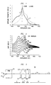
- FIG. 1 shows the base modeling parameters for a conventional Er-doped fiber (EDF), with numerals 10 and 11 referring to absorption and gain, respectively. The C-band and L-band are also indicated.
- the fiber has a numerical aperture (NA) of 0.23, a cut-off wavelength of 850nm, an Er concentration estimated at 9.0x10 25 ions/m 3 in the core, 12M% Al in the core, and adequate Ge to provide the NA of 0.23.
- the absorption curve of FIG. 1 was measured with all erbium ions in the ground state, and the gain curve was measured in the presence of a high (>300mW) 980nm pump power level, which is expected to place all the Er-ions in the excited state (full inversion).
- FIG. 2 shows the possible net gain spectra achieved by the fiber of FIG. 1. These are all linear combinations of the gain and loss spectra of FIG. 1, determined according to the formula where g* and ⁇ are the gain and loss parameters of FIG. 1, and I nv is the average inversion of the ions along the length of the fiber.
- the gain shape of the 100% inversion curve of FIG. 2 is substantially higher in the C-band than in the L-band.
- a highly inverted EDF is long enough to accumulate 10dB or more of gain across the entire L-band, some wavelengths in the C-band will experience very large gain (exemplarily 50dB, even 100dB).
- gain levels are not achieved, for the below-stated reasons.
- ASE amplified spontaneous emission
- power accumulated and emitted as ASE in the C-band is lost and is not available for emission as signal power in the L-band, thereby decreasing amplifiers efficiency.
- C-band ASE is typically the largest source of degradation in an L-band amplifier.
- EDFAs that operate in at least a portion of the L-band are know, as are EDFAs with an ASE filter.
- M. Yamada et al., Electronics Letters, Vol. 33(8), p. 710 (1997) disclose a broad band and gain-flattened amplifier that comprises a 1.55 ⁇ m band EDFA and a 1.58 ⁇ m band EDFA in parallel configuration.
- H.Ono et al., IEEE Photonics Technology Letters, Vol. 9(5), p. 596 (1997) disclose a gain-flattened EDFA for use in the 1.57-1.60 ⁇ m wavelength region. See also Y. Sun et al., Electronics Letters, Vol. 33, p. 1965 (1997). European patent application No.
- 94115479.1 inter alia discloses a 2-stage fiber amplifier with an ASE filter between the stages.
- M. Kakui et al., OFC '96 Technical Digest, WF3 disclose an EDFA that employs a chirped fiber grating as ASE rejection filter for WDM transmission.
- J.L. Zyskind et al., OFC '94 Technical Digest, WK8 disclose a 2-stage EDFA with counter-pumped first stage that comprises an ASE filter.
- U.S. patent 5,406,411 discloses a multistage fiber amplifier including an ASE filter.
- U.S. Patent 5,430,572 inter alia discloses ASE filtering for the peak around 1530nm to help the gain near 1550nm in the C-band. Such filters are low magnitude narrow band devices.
- U.S. Patent 5,701,194 discloses differential attenuation of ASE relative to a signal in a "contiguous band”. It also shows low magnitude ASE filtering near 1530nm to help C-band gain near 1550nm.
- the ASE accumulation problem could be reduced by operating the EDFA in a lower inversion condition, e.g., corresponding to the 50% inversion curve of FIG. 2.
- this solution would require use of a much longer EDF to produce the desired gain, since the gain is reduced in both C-band and L-band. This solution would also lead to significantly increased NF.
- operation of the EDFA at relatively low inversion has drawbacks that make this approach undesirable.
- the invention is embodied in an article that comprises an EDFA that is adapted for amplification of optical signals in the wavelength region 1565-1625nm, the amplifier comprising a length L of Er-doped optical fiber.
- the EDFA further comprises optical filter means, disposed in said length L of Er-doped optical fiber, with said optical filter means selected to provide the amplifier with a figure of merit greater than 400dB ⁇ nm, where said figure of merit (“FOM”) is the integral of FL ( ⁇ ) over the wavelength region from 1520nm to 1565nm, where FL ( ⁇ ) is the total loss at wavelength ⁇ due to said filter means over said length L.
- FOM figure of merit
- the optical filter means comprise one or more broad (typically covering substantially all of the C-band) and deep (loss typically greater than 10dB) filters) in the EDF.
- broad typically covering substantially all of the C-band
- deep typically greater than 10dB
- optical filter means that comprise one or more discrete filters are currently preferred, the invention is not thus limited.
- distributed filter means are possible, and are contemplated.
- Such distributed filter means are selected to provide wavelength dependent absorption in the 1520-1565nm wavelength region.
- Discrete filter elements exemplarily are selected from the group of filter elements consisting of blazed Bragg gratings, reflective mode converters, dielectric filters, fused fiber couplers and fused biconic fiber couplers. Such filter elements are known to those skilled in the art.
- the optical filter means can also be a combination of discrete and distributed filter means.
- a significant aspect of the invention is the provision of filter means in the Er-doped fiber, the filter means selected to provide the amplifier with a FOM greater than 400dB ⁇ nm, where the FOM is the integral of FL ( ⁇ ) over the wavelength region 1520-1565nm, where FL ( ⁇ ) is the total loss at ⁇ due to the optical filter means over the length L of Er-doped fiber.
- the FOM can also be expressed as follows:
- FIG. 3 schematically depicts an exemplary embodiment of the invention, namely, a L-band EDFA 30 with a multiplicity of spaced apart C-band rejection filters with large FOM.
- L-band signals are propagating from the transmitter (not shown) to the receiver (not shown) on conventional transmission fiber 31, and pump radiation is propagating from the pump source (not shown) through fiber 32 to WDM 33.
- the combined signal and pump radiation are then coupled into EDF 34 and, after passage through the length L of EDF, the amplified L-band signals typically are coupled into conventional downstream transmission fiber 31.
- C-band rejection filters 351, 352 and 353 Disposed in the EDF are several (e.g., 3) C-band rejection filters 351, 352 and 353.
- Upstream filter 351 is placed a predetermined distance L 1 from the input end of the EDF
- filter 352 is spaced a predetermined distance L 2 from filter 351
- filter 353 is spaced a predetermined distances L 3 from filter 352.
- the total length of EDF in the exemplary single state EDFA is L.
- the filters are formed in the EDF in known manner.
- a grating could be formed in a length of Er-free fiber, and the fiber with the grating therein can be spliced to appropriate lengths of EDF.
- FIG. 4 schematically shows the filter loss of two C-band filters. Both filters have 30dB filter loss.
- Curve 41 is for a substantially full C-band filter (covering the range 1520-1563nm), and curve 42 is for a partial C-band filter (exemplary covering the range 1520-1550nm).
- the pump light was assumed to be 100mW at 980nm, copropagating with the signal. It will be understood that the above parameters are exemplary only. However, the results of the simulation are representative of amplifier characteristics obtainable in actual L-band EDFAs. For instance, the modeling parameters of FIG. 1 closely correspond to the gain and absorption characteristics of an EDF that is commercially available from Lucent Technologies, Inc.
- filter spacing was chosen because this was found to be the maximum length for the fiber of FIG. 1 before ASE in the C-band reached levels in the fiber that hurt L-band performance.
- filter spacing could be less than 6m, but could also be more than 6m for a different EDF.
- FIG. 5 shows output power as a function of EDF length, as determined by the above referred to numerical simulation.
- Curve 51 assumes no filters and curves 52-56 assume, respectively, 3 filters (each 30dB) at 6, 12 and 18m; 1 filter (30dB) at 6m; 1 filter (30dB at 12m; 1 filter (30dB) at 18m; and 2 filters (each 30dB) at 6m and 12m. All filters are full C-band filters, as shown as curve 41 in FIG. 4.
- Curves 52 and 56 are essentially indistinguishable.
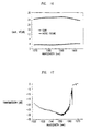
- FIG. 6 shows the worst channel NF of the above described L-band EDFA.
- Curves 61-66 correspond, respectively, to no C-band filter, 3 full C-band filters at 6, 12 and 18m; 1 full C-band filter at 6m; 1 full C-band filter at 12m; 1 full C-band filter at 18m; and 2 full C-band filters at 6 and 12m. All filters are 30dB filters.
- FIG. 6 shows that the presence of a single, appropriately placed, full C-band filter (with large FOM) can result in improved NF, but that further improvement can be obtained if more than 1 filter is used.
- FIG. 7 shows output power vs. EDF length, for no C-band filter (curve 71); 3 full C-band 30dB filters at 6m; 12m and 18m; (curve 72) 1 full C-band 30dB filter at 6m; and 1 full C-band 90dB filter at 6m (curve 74).
- the results of FIG. 7 show that, for best results, the C-band loss advantageously is distributed along the EDF, in two or more spaced apart filters.
- FIG. 8 shows worst channel NF vs. EDF length, for an L-band EDFA as described above.
- Curve 81 pertains to the case of no C-band filter
- curve 82 pertains to 3 full (30dB) C-band filters at 6, 12 and 18m; 1 full (30dB) C-band filter at 6m; and 1 full (90dB) C-band filter at 6m.
- the curves show that even a single full C-band filter of high FOM can result in improved NF.
- FIGS. 9 and 10 illustrate the effects of filter width.
- Curves 91 and 101 pertain to an EDFA without C-band filters; curves 92 and 102 pertain to the EDFA with 3 (30dB) full C-band (1520-1563nm) filters at 6, 12, and 18m, and curves 93 and 103 pertain to the EDFA with 3 (30dB) partial C-band (1520-1550nm) filters at 6, 12 and 18m.
- the curves show that substitution of partial C-band filters for the full C-band filters results in significantly smaller improvement in output power and NF.
- FIG. 11 shows output power in the L-band vs. EDF length, for the above described EDFA, with 3 full C-band filters, located at 6, 12, and 18m, with varying filter strengths.
- Curves 111-115 pertain, respectively, to no filters (i.e., 0dB); 5dB filters; 10dB filters; 20dB filters; 25dB and 30dB filters.
- the curves clearly show improvement in output power with increasing filter strength, up to about 25-30dB filter strength.
- Significant improvement e.g., 50% or more of the maximum possible
- FIG. 12 shows the worst channel NF for the above described EDFA, with curves 121-124 pertaining, respectively to no C-band filter, three 5dB filters, three 10dB filters, and three 20dB, 25dB or 30dB filters. The figure also shows that significant improvement is attainable with 2-3 full C-band filters, with about 10dB combined filter loss.
- L-band amplifier performance can be attained if a single C-band filter, of FOM greater than about 400dB ⁇ nm (e.g., filter strength 10dB or more, and filter bandwidth 40nm or more) is provided.
- the filter bandwidth is defined as full width at half maximum (FWHM), as is conventional.
- the filter has high return loss (e.g., >40dB), with minimal insertion loss (e.g., ⁇ 0.1dB) in the L-band as well as at the pump wavelength (typically 980nm or 1480nm).
- the high return loss can be achieved, for instance, by means of an isolator or circulator.
- these devices typically add undesirable insertion loss.
- FIG. 13 schematically depicts an article according to the invention, namely, an optical fiber communication system 130 that comprises an L-band EDFA according to the invention.
- Numerals 131-135 refer, respectively, to a WDM transmitter, conventional transmission fiber, the L-band EDFA, and a receiver. Conventional components (e.g., multiplexer and demultiplexer) are not shown.
- Placement of discrete optical filters into the EDF is not the only way the desired improvement in the amplifier characteristics of an L-band EDFA can be attained.
- provision of distributed loss means can have similar results.
- Such a loss means can be an appropriately selected dopant in the EDF, or an appropriately selected waveguide structure.
- the loss mechanism is active in at least a major portion of the EDF, typically in the entire EDF, and is selected to keep the maximum accumulated gain in the C-band below about 30 dB in any portion of the EDF.
- FIG. 14 schematically shows further exemplary L-band amplifier 140 according to the invention.
- the amplifier comprised two stages, an input stage (Stage 1) comprising 31m of Er-doped fiber, and an output stage (Stage 2) comprising 130m of the same Er-doped fiber.
- the fiber has a peak absorption of 6dB/m at 1530nm.
- the input stage is divided into three sections of fiber of lengths 6.5m, 4.5m and 20m, respectively, with in-line ASE filters between the sections.
- the two stages are co-pumped, with 100mW of 980nm and 110mW of 1480nm pump light, respectively. Pump light is coupled into the amplifier in conventional fashion by means of WDM couplers.
- a conventional optical isolation is disposed between the amplifier stages to prevent ASE feedback from the second into the first stage.
- Signal radiation from a conventional transmitter propagates in conventional transmission fiber to the L-band amplifier.
- Pump light (980nm) is provided by a conventional pump source (not shown) and propagates through conventional fiber 142 to WDM coupler 144 and into the amplifier input stage.
- the input stage comprises 2 in-line ASE filters 147 and 148.
- Numerals 146 and 145 refer, respectively, to a conventional optical isolator and a WDM coupler for coupling 1480nm pump light into the second amplifier stage.
- the 1480nm pump light is provided by a conventional pump light source (not shown), and propagates to the WDM coupler through fiber 143.
- the amplified signal radiation is provided to utilization means (not shown), e.g., transmission fiber that signal transmissively connects the amplifier and a receiver.
- the input saturating signal was composed of seven channels from 1570-1600nm, spaced Snm apart.
- the power in each channel was set at -20dBm, so that the total input power to the amplifier was -11.5dBm.
- the output power spectrum is shown in FIG. 15.
- the total output power was 17.1dBm when the amplifier was pumped with 100mW of 980nm and 110mW of 1480 pump light.
- the power conversion efficiency (PCE) of the amplifier was 24.3%, corresponding to 31% of the quantum limit.
- an L-band EDFA In an L-band EDFA according to the invention with two or more amplifier stages it is usually the input stage that comprises the C-band filter means.
- the length L of EDF is understood to be the length of EDF in the stage that comprises the C-band filter means.
- FIG. 16 shows the measured gain and noise of the 2-stage above described EDFA.
- the gain spectrum was obtained by tuning a small probe signal across the band and measuring its gain while the seven saturating signals were turned on.
- the magnitude of the probe signal was set at -40dBm (20dB down from the seven saturating signals) so as not to affect the gain spectrum.
- the band in which the gain of the amplifier exceeds 27dB was 33nm, and the gain variation across the band was about 1.7dB.
- a simple gain equalization filter can reduce the gain variation to below 1dB.
- the external optical noise figure across the amplifier band was below 4.5dB. It includes the loss of the WDM coupler and the splice to the erbium fiber. The lowest noise figure was 3.75dB at 1570nm, while the highest was 4.45dB at 1602nm.
- FIG. 17 shows the transmission spectrum of a blazed fiber Bragg grating that is suitable for use in the above described exemplary amplifier according to the invention.
- a grating is prepared as follows. Conventional optical fiber (5D fiber available from Lucent Technologies) is loaded with deuterium in conventional fashion and a chirped, blazed Bragg grating is written into the fiber core by UV (242nm) exposure through a phase mask. The nominal phase mask period is 1.076nm, and the chirp in phase mask period is 2nm/cm. The length of grating is 1.5cm and its profile is approximately Gaussian. The grating blaze is achieved by tilting the phase mask with respect to the fiber. Each filter of the amplifier is comprised of two gratings with phase mask tilt of 3.5 and 6 degrees, giving maximum cladding mode loss near 1560nm and 1530nm respectively. The refractive index modulation in each grating is approximately 0.003.
- Conventional optical fiber (5D fiber available from Lucent Technologies) is loaded with deuterium
Abstract
Description
- This invention pertains to articles (e.g., an optical fiber communication system, or a component for use in such a system) that comprise an L-Band optical fiber amplifier.
- Er-doped fiber amplifiers (EDFAs) are widely used in optical fiber communication systems. Traditionally, EDFAs are used in the wavelength range from about 1525nm to about 1565nm, a range that is commonly referred to as the C-band (when "C" stands for "conventional").
- A significant fraction of installed optical fiber (e.g., dispersion-shifted fiber) is not suitable for multichannel dense wavelength division multiplexed (DWDM) operation across the entire C-band wavelength range because of nonlinear effects such as four-wave mixing. Thus, it would be advantageous to have available an optical fiber amplifier that can operate in a wavelength regime that includes the operating wavelength of the above referred to installed optical fiber, typically greater than 1565nm.
- Recently use of EDFAs in the approximate range 1565-1625nm has been reported See, for instance, J.F. Massicott et al., Electronics Letters, Vol. 28, pp. 1924-1925 (1992). This range is now commonly called the L-band, where "L" stands for "long". Operation in both the C-band and the L-band in a single EDFA has also been reported. See Y. Sun et al., Proceedings of the European Conference on Optical Communication (ECOC '98), pp. 53-54 (1998).
- To date, the reported performance of L-band EDFAs has been inferior to that routinely available in C-band EDFAs. For instance, the noise figure (NF) of L-band EDFAs has generally been 1-2 dB higher than for C-band EDFAs, and the output power of the former has typically been 1 to several dBs lower than that of the latter. In view of the potential advantages of a L-band EDFA, it would be highly desirable to have available a L-band EDFA with improved performance, desirably comparable to that of C-band EDFAs. This application discloses such an EDFA.
- FIG. 1 shows the base modeling parameters for a conventional Er-doped fiber (EDF), with
numerals 10 and 11 referring to absorption and gain, respectively. The C-band and L-band are also indicated. The fiber has a numerical aperture (NA) of 0.23, a cut-off wavelength of 850nm, an Er concentration estimated at 9.0x1025 ions/m3 in the core, 12M% Al in the core, and adequate Ge to provide the NA of 0.23. The absorption curve of FIG. 1 was measured with all erbium ions in the ground state, and the gain curve was measured in the presence of a high (>300mW) 980nm pump power level, which is expected to place all the Er-ions in the excited state (full inversion). - FIG. 2 shows the possible net gain spectra achieved by the fiber of FIG. 1. These are all linear combinations of the gain and loss spectra of FIG. 1, determined according to the formulawhere g* and α are the gain and loss parameters of FIG. 1, and

I nv is the average inversion of the ions along the length of the fiber. - It is known that, in order to achieve a low noise figure (NF) in an EDFA, substantially all ions must be in the excited state. This produces the 100% inversion gain of FIG. 2. In practice, achieving this high inversion gain shape over a substantial portion of the input end of an EDFA (exemplarily enough to produce more than about 10dB of gain) is adequate to provide a low NF.
- It will be noticed that the gain shape of the 100% inversion curve of FIG. 2 is substantially higher in the C-band than in the L-band. Thus, if a highly inverted EDF is long enough to accumulate 10dB or more of gain across the entire L-band, some wavelengths in the C-band will experience very large gain (exemplarily 50dB, even 100dB). In practice, such gain levels are not achieved, for the below-stated reasons. We have analyzed this situation and have found that amplified spontaneous emission (ASE) in the C-band accumulates to a high power level and drives a substantial fraction of the Er ions into the ground state, thereby reducing the gain and increasing the NF. Furthermore, power accumulated and emitted as ASE in the C-band is lost and is not available for emission as signal power in the L-band, thereby decreasing amplifiers efficiency.
- Based on our analysis, we have concluded that C-band ASE is typically the largest source of degradation in an L-band amplifier.
- EDFAs that operate in at least a portion of the L-band are know, as are EDFAs with an ASE filter. For instance, M. Yamada et al., Electronics Letters, Vol. 33(8), p. 710 (1997) disclose a broad band and gain-flattened amplifier that comprises a 1.55µm band EDFA and a 1.58µm band EDFA in parallel configuration. H.Ono et al., IEEE Photonics Technology Letters, Vol. 9(5), p. 596 (1997) disclose a gain-flattened EDFA for use in the 1.57-1.60µm wavelength region. See also Y. Sun et al., Electronics Letters, Vol. 33, p. 1965 (1997). European patent application No. 94115479.1 inter alia discloses a 2-stage fiber amplifier with an ASE filter between the stages. M. Kakui et al., OFC '96 Technical Digest, WF3, disclose an EDFA that employs a chirped fiber grating as ASE rejection filter for WDM transmission. J.L. Zyskind et al., OFC '94 Technical Digest, WK8, disclose a 2-stage EDFA with counter-pumped first stage that comprises an ASE filter. U.S. patent 5,406,411 discloses a multistage fiber amplifier including an ASE filter.
- U.S. Patent 5,430,572 inter alia discloses ASE filtering for the peak around 1530nm to help the gain near 1550nm in the C-band. Such filters are low magnitude narrow band devices. U.S. Patent 5,701,194 discloses differential attenuation of ASE relative to a signal in a "contiguous band". It also shows low magnitude ASE filtering near 1530nm to help C-band gain near 1550nm.
- As discussed above, our analysis of L-band EDFAs has led to the conclusion that C-band ASE is the largest source of degradation in an L-band amplifier.
- The ASE accumulation problem could be reduced by operating the EDFA in a lower inversion condition, e.g., corresponding to the 50% inversion curve of FIG. 2. However, this solution would require use of a much longer EDF to produce the desired gain, since the gain is reduced in both C-band and L-band. This solution would also lead to significantly increased NF. Clearly, operation of the EDFA at relatively low inversion has drawbacks that make this approach undesirable.
- We have discovered that placement of appropriate filter means into the EDFA can result in substantial improvement in amplifier characteristics.
- Specifically, the invention is embodied in an article that comprises an EDFA that is adapted for amplification of optical signals in the wavelength region 1565-1625nm, the amplifier comprising a length L of Er-doped optical fiber.
- Significantly, the EDFA further comprises optical filter means, disposed in said length L of Er-doped optical fiber, with said optical filter means selected to provide the amplifier with a figure of merit greater than 400dB·nm, where said figure of merit ("FOM") is the integral of FL (λ) over the wavelength region from 1520nm to 1565nm, where FL (λ) is the total loss at wavelength λ due to said filter means over said length L.
- In currently preferred embodiments the optical filter means comprise one or more broad (typically covering substantially all of the C-band) and deep (loss typically greater than 10dB) filters) in the EDF. To the best of our knowledge, such an EDFA is not disclosed or suggested by the prior art.
- Whereas improved amplifier characteristics can be obtained with a single broad and deep filter (e.g., about 40nm and 10dB), even better results can frequently be obtained with two or more filters selected to yield a FOM>400dB·nm and disposed at different positions along the EDF.
- Although optical filter means that comprise one or more discrete filters are currently preferred, the invention is not thus limited. For instance, distributed filter means are possible, and are contemplated. Such distributed filter means are selected to provide wavelength dependent absorption in the 1520-1565nm wavelength region. Discrete filter elements exemplarily are selected from the group of filter elements consisting of blazed Bragg gratings, reflective mode converters, dielectric filters, fused fiber couplers and fused biconic fiber couplers. Such filter elements are known to those skilled in the art. The optical filter means can also be a combination of discrete and distributed filter means.
-
- FIG. 1 shows the modeling parameters of a commercially available EDF as a function of wavelength;
- FIG. 2 shows gain as a function of wavelength, for various levels of ion inversion;
- FIG. 3 schematically depicts an exemplary L-band EDFA according to the invention;
- FIG. 4 schematically shows the filter loss of a full C-band filter and of a partial C-band filter,
- FIGs. 5-12 show simulation results for EDFAs according to the invention, and for an EDFA without C-band rejection filter,
- FIG. 13 schematically shows a WDM fiber transmission system with L-band EDFA;
- FIG. 14 schematically shows an exemplary L-band EDFA according to the invention;
- FIG. 15 shows the output spectrum of an EDFA according to the invention;
- FIG. 16 shows gain and noise figure of an EDFA according to the invention; and
- FIG. 17 shows the transmission spectrum of an exemplary blazed fiber Bragg grating.
-
- The drawings are not to scale or in proportion.
- A significant aspect of the invention is the provision of filter means in the Er-doped fiber, the filter means selected to provide the amplifier with a FOM greater than 400dB·nm, where the FOM is the integral of FL (λ) over the wavelength region 1520-1565nm, where FL (λ) is the total loss at λ due to the optical filter means over the length L of Er-doped fiber.
- The FOM can also be expressed as follows:

- The above expression allows for the existence of n discrete filtering devices with losses FL1 (λ), FL2(λ),...FLn(λ), expressed in dB, the devices located at position z1,z2,...zn within the length L of EDF. It also allows the presence of a distributed unsaturable loss αd (λ,z), expressed in dB/m. In the expression, integration is over the spectral region from a=1520nm to b=1565nm, and over the EDFA length, i.e., z=0 to L.
- The above expression is the sum of all C-band losses in an L-band EDFA, whether due to discrete or distributed filter means.
- FIG. 3 schematically depicts an exemplary embodiment of the invention, namely, a L-
band EDFA 30 with a multiplicity of spaced apart C-band rejection filters with large FOM. L-band signals are propagating from the transmitter (not shown) to the receiver (not shown) onconventional transmission fiber 31, and pump radiation is propagating from the pump source (not shown) throughfiber 32 toWDM 33. The combined signal and pump radiation are then coupled intoEDF 34 and, after passage through the length L of EDF, the amplified L-band signals typically are coupled into conventionaldownstream transmission fiber 31. - Disposed in the EDF are several (e.g., 3) C-band rejection filters 351, 352 and 353. Upstream filter 351 is placed a predetermined distance L1 from the input end of the EDF, filter 352 is spaced a predetermined distance L2 from filter 351, and filter 353 is spaced a predetermined distances L3 from filter 352. The total length of EDF in the exemplary single state EDFA is L.
- In preferred embodiments the filters are formed in the EDF in known manner. However, this is not a requirement, and a grating could be formed in a length of Er-free fiber, and the fiber with the grating therein can be spliced to appropriate lengths of EDF.
- FIG. 4 schematically shows the filter loss of two C-band filters. Both filters have 30dB filter loss. Curve 41 is for a substantially full C-band filter (covering the range 1520-1563nm), and curve 42 is for a partial C-band filter (exemplary covering the range 1520-1550nm). The former has FOM=1290dB·nm, and the latter has FOM=900dB·nm.
- The data of FIG. 1, together with the filter characteristics of FIG. 4, were used in a conventional numerical simulation (using the OASIX simulation tool, which is commercially available from Lucent Technologies' Specialty Fiber Division) of the characteristics of an EDFA as shown in FIG. 3, for total signal power of -10dBm, L-1=L2=L3=6m, and L as shown. The pump light was assumed to be 100mW at 980nm, copropagating with the signal. It will be understood that the above parameters are exemplary only. However, the results of the simulation are representative of amplifier characteristics obtainable in actual L-band EDFAs. For instance, the modeling parameters of FIG. 1 closely correspond to the gain and absorption characteristics of an EDF that is commercially available from Lucent Technologies, Inc. The filter spacing of 6m was chosen because this was found to be the maximum length for the fiber of FIG. 1 before ASE in the C-band reached levels in the fiber that hurt L-band performance. Clearly, filter spacing could be less than 6m, but could also be more than 6m for a different EDF.
- FIG. 5 shows output power as a function of EDF length, as determined by the above referred to numerical simulation.
Curve 51 assumes no filters and curves 52-56 assume, respectively, 3 filters (each 30dB) at 6, 12 and 18m; 1 filter (30dB) at 6m; 1 filter (30dB at 12m; 1 filter (30dB) at 18m; and 2 filters (each 30dB) at 6m and 12m. All filters are full C-band filters, as shown as curve 41 in FIG. 4. Curves 52 and 56 are essentially indistinguishable. - The simulation clearly shows that even a single, properly placed, full C-band filter yields significantly improved output power, and also shows that further significant improvement is obtained if more than 1 filter is used.
- FIG. 6 shows the worst channel NF of the above described L-band EDFA. Curves 61-66 correspond, respectively, to no C-band filter, 3 full C-band filters at 6, 12 and 18m; 1 full C-band filter at 6m; 1 full C-band filter at 12m; 1 full C-band filter at 18m; and 2 full C-band filters at 6 and 12m. All filters are 30dB filters. FIG. 6 shows that the presence of a single, appropriately placed, full C-band filter (with large FOM) can result in improved NF, but that further improvement can be obtained if more than 1 filter is used.
- FIG. 7 shows output power vs. EDF length, for no C-band filter (curve 71); 3 full C-band 30dB filters at 6m; 12m and 18m; (curve 72) 1 full C-band 30dB filter at 6m; and 1 full C-band 90dB filter at 6m (curve 74). The results of FIG. 7 show that, for best results, the C-band loss advantageously is distributed along the EDF, in two or more spaced apart filters.
- FIG. 8 shows worst channel NF vs. EDF length, for an L-band EDFA as described above.
Curve 81 pertains to the case of no C-band filter, and curve 82 pertains to 3 full (30dB) C-band filters at 6, 12 and 18m; 1 full (30dB) C-band filter at 6m; and 1 full (90dB) C-band filter at 6m. The curves show that even a single full C-band filter of high FOM can result in improved NF. - FIGS. 9 and 10 illustrate the effects of filter width.
Curves 91 and 101 pertain to an EDFA without C-band filters; curves 92 and 102 pertain to the EDFA with 3 (30dB) full C-band (1520-1563nm) filters at 6, 12, and 18m, and curves 93 and 103 pertain to the EDFA with 3 (30dB) partial C-band (1520-1550nm) filters at 6, 12 and 18m. The curves show that substitution of partial C-band filters for the full C-band filters results in significantly smaller improvement in output power and NF. - FIG. 11 shows output power in the L-band vs. EDF length, for the above described EDFA, with 3 full C-band filters, located at 6, 12, and 18m, with varying filter strengths. Curves 111-115 pertain, respectively, to no filters (i.e., 0dB); 5dB filters; 10dB filters; 20dB filters; 25dB and 30dB filters. The curves clearly show improvement in output power with increasing filter strength, up to about 25-30dB filter strength. Significant improvement (e.g., 50% or more of the maximum possible) is attainable with 2 or 3 full C-band filters, with about 10dB combined filter loss.
- FIG. 12 shows the worst channel NF for the above described EDFA, with curves 121-124 pertaining, respectively to no C-band filter, three 5dB filters, three 10dB filters, and three 20dB, 25dB or 30dB filters. The figure also shows that significant improvement is attainable with 2-3 full C-band filters, with about 10dB combined filter loss.
- Some improvement in L-band amplifier performance can be attained if a single C-band filter, of FOM greater than about 400dB·nm (e.g., filter strength 10dB or more, and filter bandwidth 40nm or more) is provided. The filter bandwidth is defined as full width at half maximum (FWHM), as is conventional.
- The above disclosed results are exemplary of attainable results, but the invention is not limited to the disclosed embodiments. A variety of C-band rejection filters can result in significantly improved L-band performance and are contemplated. Desirably, the filter has high return loss (e.g., >40dB), with minimal insertion loss (e.g., <0.1dB) in the L-band as well as at the pump wavelength (typically 980nm or 1480nm). The high return loss can be achieved, for instance, by means of an isolator or circulator. However, these devices typically add undesirable insertion loss.
- The above recited simulation results of an exemplary EDFA according to the invention can be compared to simulation results substantially corresponding to a prior art EDFA. Assumed were 100mW of 980nm pump light, -lOdBm total signal input into the C-band with 16 channels from 1545-1560nm (1nm spacing), with a 20dB ASE filter (as shown in FIG. 4, except for different strength and width) from 1525nm to 1540nm in the C-band. The above described fiber and amplifier configuration were used in the simulation. We found that in this case 5m filter spacing was optimal. The substantial maximum improvement in output power and NF was reached with a single 15dB filter with bandwidth 1525-1540nm. The use of two filters produced substantially no improvement. The maximum needed filter FOM is 300dB·nm (20dB at 15nm). This FOM is, to the best of our knowledge, larger than any FOM used in prior practice. C-band ASE filters with FOM=300dB·nm produced only minor improvement for L-band EDFA.
- Filters that have bandwidth of 30nm or more, with strength that is substantially flat over most of the bandwidth are known. See, for instance, A. Vengsarkar et al., OFC '95, PD4-1; Erdogan et al., J. of the Optical Society of America A, Vol. 13, pp. 296-313 (1996); and U.S. Patent No. 5,740,292.
- FIG. 13 schematically depicts an article according to the invention, namely, an optical fiber communication system 130 that comprises an L-band EDFA according to the invention. Numerals 131-135 refer, respectively, to a WDM transmitter, conventional transmission fiber, the L-band EDFA, and a receiver. Conventional components (e.g., multiplexer and demultiplexer) are not shown.
- Placement of discrete optical filters into the EDF is not the only way the desired improvement in the amplifier characteristics of an L-band EDFA can be attained. For instance, provision of distributed loss means can have similar results. Such a loss means can be an appropriately selected dopant in the EDF, or an appropriately selected waveguide structure. The loss mechanism is active in at least a major portion of the EDF, typically in the entire EDF, and is selected to keep the maximum accumulated gain in the C-band below about 30 dB in any portion of the EDF.
- FIG. 14 schematically shows further exemplary L-
band amplifier 140 according to the invention. The amplifier comprised two stages, an input stage (Stage 1) comprising 31m of Er-doped fiber, and an output stage (Stage 2) comprising 130m of the same Er-doped fiber. The fiber has a peak absorption of 6dB/m at 1530nm. The input stage is divided into three sections of fiber of lengths 6.5m, 4.5m and 20m, respectively, with in-line ASE filters between the sections. The two stages are co-pumped, with 100mW of 980nm and 110mW of 1480nm pump light, respectively. Pump light is coupled into the amplifier in conventional fashion by means of WDM couplers. A conventional optical isolation is disposed between the amplifier stages to prevent ASE feedback from the second into the first stage. Signal radiation from a conventional transmitter (not shown) propagates in conventional transmission fiber to the L-band amplifier. Pump light (980nm) is provided by a conventional pump source (not shown) and propagates throughconventional fiber 142 toWDM coupler 144 and into the amplifier input stage. The input stage comprises 2 in-line ASE filters 147 and 148.Numerals 146 and 145 refer, respectively, to a conventional optical isolator and a WDM coupler for coupling 1480nm pump light into the second amplifier stage. The 1480nm pump light is provided by a conventional pump light source (not shown), and propagates to the WDM coupler throughfiber 143. The amplified signal radiation is provided to utilization means (not shown), e.g., transmission fiber that signal transmissively connects the amplifier and a receiver. - We measured the performance of the above-described 2-stage L-band optical amplifier. The input saturating signal was composed of seven channels from 1570-1600nm, spaced Snm apart. The power in each channel was set at -20dBm, so that the total input power to the amplifier was -11.5dBm. The output power spectrum is shown in FIG. 15. The total output power was 17.1dBm when the amplifier was pumped with 100mW of 980nm and 110mW of 1480 pump light. The power conversion efficiency (PCE) of the amplifier was 24.3%, corresponding to 31% of the quantum limit.
- In an L-band EDFA according to the invention with two or more amplifier stages it is usually the input stage that comprises the C-band filter means. In an EDFA with two or more stages the length L of EDF is understood to be the length of EDF in the stage that comprises the C-band filter means.
- FIG. 16 shows the measured gain and noise of the 2-stage above described EDFA. The gain spectrum was obtained by tuning a small probe signal across the band and measuring its gain while the seven saturating signals were turned on. The magnitude of the probe signal was set at
-40dBm (20dB down from the seven saturating signals) so as not to affect the gain spectrum. The band in which the gain of the amplifier exceeds 27dB was 33nm, and the gain variation across the band was about 1.7dB. A simple gain equalization filter can reduce the gain variation to below 1dB. The external optical noise figure across the amplifier band was below 4.5dB. It includes the loss of the WDM coupler and the splice to the erbium fiber. The lowest noise figure was 3.75dB at 1570nm, while the highest was 4.45dB at 1602nm. - FIG. 17 shows the transmission spectrum of a blazed fiber Bragg grating that is suitable for use in the above described exemplary amplifier according to the invention. A grating is prepared as follows. Conventional optical fiber (5D fiber available from Lucent Technologies) is loaded with deuterium in conventional fashion and a chirped, blazed Bragg grating is written into the fiber core by UV (242nm) exposure through a phase mask. The nominal phase mask period is 1.076nm, and the chirp in phase mask period is 2nm/cm. The length of grating is 1.5cm and its profile is approximately Gaussian. The grating blaze is achieved by tilting the phase mask with respect to the fiber. Each filter of the amplifier is comprised of two gratings with phase mask tilt of 3.5 and 6 degrees, giving maximum cladding mode loss near 1560nm and 1530nm respectively. The refractive index modulation in each grating is approximately 0.003.
Claims (10)
- An article comprising an Er-doped fiber amplifier that is adapted for amplification of optical signal radiation in the approximate wavelength region 1565-1625nm, the amplifier comprising a length L of Er-doped optical fiber having an input, and also comprising a coupler or couplers for coupling said optical signal radiation and a pump light into said Er-doped optical fiber;
CHARACTERIZED IN THAT
the amplifier further comprises optical filter means, disposed in said length L of Er-doped optical fiber, with said optical filter means selected to provide the amplifier with a figure of merit greater than 400dB·nm, where said figure of merit is the integral of FL(λ) over the wavelength region from 1520-1565nm, where FL(λ) is the total loss at wavelength λ due to said optical filter means over said length L of Er-doped optical fiber, said figure of merit to be designated "FOM". - Article according to claim 1, wherein said optical filter means are selected to provide wavelength dependent absorption in said 1520-1565 nm wavelength region.
- Article comprising to claim 1, wherein said optical filter means comprise at least one discrete filter element selected to provide filtering in said 1520-1565nm wavelength region.
- Article according to claim 3, wherein said at least one discrete filter element is selected from the group of filter elements consisting of blazed Bragg gratings, long period fiber gratings, reflective mode converters, dielectric filters, fused fiber couplers, and fused biconic fiber couplers.
- Article according to claim 3, wherein said at least one discrete filter element is a blazed Bragg grating.
- Article according to claim 1, wherein said Er-doped fiber amplifier is a multistage fiber amplifier having an input stage, with said optical filter means disposed in said input stage.
- Article according to claim 3, wherein said optical filter means further comprise distributed filter means selected to provide wavelength dependent absorption in the 1520-1565 wavelength region.
- Article according to claim 1, wherein said FOM is greater than 500dB·nm.
- Article according to claim 3, wherein said optical filter means comprise two or more discrete filter elements.
- Article according to claim 9, wherein said two or more discrete filter elements are blazed Bragg gratings.
Applications Claiming Priority (2)
| Application Number | Priority Date | Filing Date | Title |
|---|---|---|---|
| US09/252,560 US6141142A (en) | 1999-02-19 | 1999-02-19 | Article comprising an L-Band optical fiber amplifier |
| US252560 | 1999-02-19 |
Publications (2)
| Publication Number | Publication Date |
|---|---|
| EP1030414A1 true EP1030414A1 (en) | 2000-08-23 |
| EP1030414B1 EP1030414B1 (en) | 2003-01-22 |
Family
ID=22956527
Family Applications (1)
| Application Number | Title | Priority Date | Filing Date |
|---|---|---|---|
| EP00300983A Expired - Lifetime EP1030414B1 (en) | 1999-02-19 | 2000-02-09 | Article comprising an L-band optical fiber amplifier |
Country Status (4)
| Country | Link |
|---|---|
| US (1) | US6141142A (en) |
| EP (1) | EP1030414B1 (en) |
| JP (1) | JP3634708B2 (en) |
| DE (1) | DE60001239T2 (en) |
Cited By (2)
| Publication number | Priority date | Publication date | Assignee | Title |
|---|---|---|---|---|
| EP1286432A3 (en) * | 2001-08-22 | 2005-02-23 | Fujitsu Limited | Optical amplifier and gain tilt compensation method |
| CN108133650A (en) * | 2017-06-22 | 2018-06-08 | 杭州电子科技大学 | The EDFA Instructional Development experimental boxs of C+L wave bands |
Families Citing this family (25)
| Publication number | Priority date | Publication date | Assignee | Title |
|---|---|---|---|---|
| KR100326119B1 (en) * | 1999-06-23 | 2002-03-07 | 윤종용 | L-band optical fiber amplifier by use of seed beam |
| US6459526B1 (en) * | 1999-08-09 | 2002-10-01 | Corning Incorporated | L band amplifier with distributed filtering |
| US6396624B1 (en) * | 2000-01-11 | 2002-05-28 | Tycom (Us) Inc. | Extended band erbium doped fiber amplifier |
| US6697558B2 (en) | 2000-03-03 | 2004-02-24 | Fitel U.S.A. Corp | Raman amplified optical system with reduction of four-wave mixing effects |
| US6441953B1 (en) * | 2000-04-24 | 2002-08-27 | Corning Incorporated | L band multistage amplifier with improved noise figure |
| US6507430B2 (en) | 2001-02-23 | 2003-01-14 | Photon X, Inc. | Long wavelength optical amplifier |
| US6731426B2 (en) | 2001-02-23 | 2004-05-04 | Photon-X, Inc. | Long wavelength optical amplifier |
| US6618193B1 (en) * | 2001-03-26 | 2003-09-09 | Nortel Networks Limited | Optical amplification systems and methods |
| KR100394457B1 (en) * | 2001-05-08 | 2003-08-14 | 주식회사 네오텍리서치 | Erbium-doped fiber laser for long wavelength band |
| KR100388355B1 (en) * | 2001-08-03 | 2003-06-25 | 학교법인 성균관대학 | A stabilized fiber grating semiconductor laser |
| CN1324829C (en) * | 2001-08-03 | 2007-07-04 | 华为技术有限公司 | Method for implementing power equalization of dense wavelength divison multiplex system |
| US6927898B2 (en) * | 2001-08-15 | 2005-08-09 | Photon-X, Llc | Ultra-wide bandwidth optical amplifier |
| US6781748B2 (en) | 2001-09-28 | 2004-08-24 | Photon-X, Llc | Long wavelength optical amplifier |
| WO2003044569A2 (en) * | 2001-11-19 | 2003-05-30 | Photon-X, Inc. | L band optical amplifier |
| JP2005051196A (en) * | 2003-07-15 | 2005-02-24 | Furukawa Electric Co Ltd:The | Erbium-doped optical fiber amplifier |
| US7209283B2 (en) * | 2004-04-07 | 2007-04-24 | Avago Technologies Fiber Ip (Singapore) Pte. Ltd. | Compact optical amplifier with a flattened gain profile |
| US7272287B2 (en) * | 2005-05-11 | 2007-09-18 | Fitel Usa Corp | Optical fiber filter for suppression of amplified spontaneous emission |
| US10510043B2 (en) * | 2005-06-13 | 2019-12-17 | Skyword Inc. | Computer method and apparatus for targeting advertising |
| US8744224B2 (en) * | 2006-03-07 | 2014-06-03 | Alcatel Lucent | Tapered fiber bundle apparatus with monitoring capability |
| US7724423B2 (en) * | 2006-03-16 | 2010-05-25 | Alcatel-Lucent Usa Inc. | Optical fiber laser having improved efficiency |
| JP2011249531A (en) | 2010-05-26 | 2011-12-08 | Fujitsu Ltd | Optical amplifier device and optical amplifier medium |
| CA2971601C (en) | 2017-01-27 | 2022-06-21 | Teraxion Inc. | Optical fiber filter of wideband deleterious light and uses thereof |
| US10591667B2 (en) | 2017-05-19 | 2020-03-17 | Ofs Fitel, Llc | Optical fiber with specialized figure-of-merit and applications therefor |
| CN108183386B (en) * | 2018-01-16 | 2019-07-09 | 浙江大学 | A kind of Er-Doped superfluorescent fiber source device based on chirped fiber Bragg grating filtering |
| JP7427770B2 (en) * | 2019-08-21 | 2024-02-05 | オーエフエス ファイテル,エルエルシー | Optical fiber amplifier with distributed gain flattening |
Citations (2)
| Publication number | Priority date | Publication date | Assignee | Title |
|---|---|---|---|---|
| US5740292A (en) * | 1996-09-12 | 1998-04-14 | Lucent Technologies Inc. | Mode coupling optical waveguide grating |
| EP0897205A2 (en) * | 1997-08-11 | 1999-02-17 | Fujitsu Limited | Method and device for optical amplification and system having the device |
Family Cites Families (8)
| Publication number | Priority date | Publication date | Assignee | Title |
|---|---|---|---|---|
| GB897205A (en) * | 1959-10-19 | 1962-05-23 | Ici Ltd | Precipitated calcium carbonate |
| US5117303A (en) * | 1990-08-23 | 1992-05-26 | At&T Bell Laboratories | Method of operating concatenated optical amplifiers |
| US5430572A (en) * | 1993-09-30 | 1995-07-04 | At&T Corp. | High power, high gain, low noise, two-stage optical amplifier |
| US5406411A (en) * | 1993-10-14 | 1995-04-11 | Corning Incorporated | Fiber amplifier having efficient pump power utilization |
| PE41196A1 (en) * | 1994-07-25 | 1996-12-17 | Pirelli Cavi Spa | AMPLIFIED TELECOMMUNICATION SYSTEM FOR MULTIPLEX TRANSMISSIONS BY WAVE LENGTH DIVISION, ABLE TO LIMIT THE VARIATIONS IN THE OUTPUT POWER |
| JP4075113B2 (en) * | 1997-11-07 | 2008-04-16 | 住友電気工業株式会社 | Optical fiber amplifier and erbium-doped optical fiber |
| JP3519926B2 (en) * | 1997-11-12 | 2004-04-19 | 古河電気工業株式会社 | WDM optical communication system and its optical amplifier |
| US6049418A (en) * | 1998-02-06 | 2000-04-11 | Lucent Technologies, Inc. | Noise figure in optical amplifiers with a split-band architecture |
-
1999
- 1999-02-19 US US09/252,560 patent/US6141142A/en not_active Expired - Lifetime
-
2000
- 2000-02-09 EP EP00300983A patent/EP1030414B1/en not_active Expired - Lifetime
- 2000-02-09 DE DE60001239T patent/DE60001239T2/en not_active Expired - Lifetime
- 2000-02-14 JP JP2000035783A patent/JP3634708B2/en not_active Expired - Fee Related
Patent Citations (2)
| Publication number | Priority date | Publication date | Assignee | Title |
|---|---|---|---|---|
| US5740292A (en) * | 1996-09-12 | 1998-04-14 | Lucent Technologies Inc. | Mode coupling optical waveguide grating |
| EP0897205A2 (en) * | 1997-08-11 | 1999-02-17 | Fujitsu Limited | Method and device for optical amplification and system having the device |
Non-Patent Citations (4)
| Title |
|---|
| SUN Y ET AL: "AN 80 NM ULTRA WIDE BAND EDFA WITH LOW NOISE FIGURE AND HIGH OUTPUT POWER", IOOC-ECOC. EUROPEAN CONFERENCE ON OPTICAL COMMUNICATION ECOC. INTERNATIONAL CONFERENCE ON INTEGRATED OPTICS AND OPTICAL FIBRE COMMUNICATION IOOC,XX,XX, vol. 5, 1 January 1997 (1997-01-01), pages 69 - 72, XP002074523 * |
| SUZUKI K -I ET AL: "BIDIRECTIONAL 10-CHANNEL 2.5 GIIT/S WDM TRANSMISSION OVER 250 KM USING 76 NM (1531-1607NM) GAIN-BAND BIDIRECTIONAL ERBIUM-DOPED FIBRE AMPLIFIERS", ELECTRONICS LETTERS,GB,IEE STEVENAGE, vol. 33, no. 23, 6 November 1997 (1997-11-06), pages 1967 - 1968, XP000773534, ISSN: 0013-5194 * |
| WYSOCKI P F ET AL: "BROAD-BAND ERBIUM-DOPED FIBER AMPLIFIER FLATTENED BEYOND 40 NM USING LONG-PERIOD GRATING FILTER", IEEE PHOTONICS TECHNOLOGY LETTERS,US,IEEE INC. NEW YORK, vol. 9, no. 10, 1 October 1997 (1997-10-01), pages 1343 - 1345, XP000721334, ISSN: 1041-1135 * |
| YAMADA M ET AL: "GAIN-FLATTENED TELLURITE-BASED EDFA WITH A FLAT AMPLIFICATION BANDWIDTH OF 76 NM", IEEE PHOTONICS TECHNOLOGY LETTERS,US,IEEE INC. NEW YORK, vol. 10, no. 9, 1 September 1998 (1998-09-01), pages 1244 - 1246, XP000783223, ISSN: 1041-1135 * |
Cited By (3)
| Publication number | Priority date | Publication date | Assignee | Title |
|---|---|---|---|---|
| EP1286432A3 (en) * | 2001-08-22 | 2005-02-23 | Fujitsu Limited | Optical amplifier and gain tilt compensation method |
| CN108133650A (en) * | 2017-06-22 | 2018-06-08 | 杭州电子科技大学 | The EDFA Instructional Development experimental boxs of C+L wave bands |
| CN108133650B (en) * | 2017-06-22 | 2019-10-18 | 杭州电子科技大学 | The EDFA Instructional Development experimental box of C+L wave band |
Also Published As
| Publication number | Publication date |
|---|---|
| JP2000244040A (en) | 2000-09-08 |
| EP1030414B1 (en) | 2003-01-22 |
| DE60001239D1 (en) | 2003-02-27 |
| DE60001239T2 (en) | 2003-10-30 |
| JP3634708B2 (en) | 2005-03-30 |
| US6141142A (en) | 2000-10-31 |
Similar Documents
| Publication | Publication Date | Title |
|---|---|---|
| EP1030414B1 (en) | Article comprising an L-band optical fiber amplifier | |
| US5260823A (en) | Erbium-doped fibre amplifier with shaped spectral gain | |
| JP4900501B2 (en) | Optical amplifier and optical amplification method | |
| EP0535002B1 (en) | Erbium-doped fibre amplifier with shaped spectral gain | |
| US6903865B2 (en) | Communication system using S-band Er-doped fiber amplifiers with depressed cladding | |
| KR100686417B1 (en) | Optical fiber amplifier having a gnin flattening filter | |
| KR100424772B1 (en) | Optical amplifier system | |
| Choi et al. | New pump wavelength of 1540-nm band for long-wavelength-band erbium-doped fiber amplifier (L-band EDFA) | |
| EP1525648B1 (en) | Multi-stage raman amplifier | |
| KR100498952B1 (en) | Gain-flattened wide-band erbium doped optical fiber amplifier | |
| Sun et al. | An 80 nm ultra wide band EDFA with low noise figure and high output power | |
| KR20010041602A (en) | Ultra-Broadband Low-Noise Gain-Flattened Rare-Earth-Doped Fibre Amplifier | |
| US6473549B1 (en) | Multi-stage fiber amplifier with flattened gain curves | |
| US8064130B2 (en) | Optical amplifier | |
| Talam et al. | EDFA gain flattening using fiber Bragg gratings employing different host materials | |
| US6961502B1 (en) | Optical module including an optically lossy component and an erbium-doped waveguide for insertion between stages of an optical amplifier | |
| Delavaux et al. | Gain flatness of a planar optical waveguide amplifier | |
| Kakui et al. | Long-wavelength-band optical amplifiers employing silica-based erbium doped fibers designed for wavelength division multiplexing systems and networks | |
| EP0944939B1 (en) | Fiber amplifier with reduced temperature dependent gain flatness distortion | |
| US7999999B2 (en) | Article comprising a multichannel optical amplified transmission system with functional upgrade capabilities and universal modules | |
| JP4568247B2 (en) | Optical amplification module and optical amplifier including the same | |
| Karasek | Design of gain-shifted erbium-doped fibre amplifiers for WDM applications | |
| CN115552812A (en) | Optical fiber amplifier, wavelength division multiplexing system and optical communication equipment | |
| Anthony et al. | Design optimization of erbium-doped fiber ring laser for C and L band amplification incorporating chirped fiber Bragg grating | |
| EP1005707A1 (en) | Gain tilt control with mid-stage attenuators in erbium-doped fiber amplifiers |
Legal Events
| Date | Code | Title | Description |
|---|---|---|---|
| PUAI | Public reference made under article 153(3) epc to a published international application that has entered the european phase |
Free format text: ORIGINAL CODE: 0009012 |
|
| 17P | Request for examination filed |
Effective date: 20000218 |
|
| AK | Designated contracting states |
Kind code of ref document: A1 Designated state(s): DE FR GB |
|
| AX | Request for extension of the european patent |
Free format text: AL;LT;LV;MK;RO;SI |
|
| 17Q | First examination report despatched |
Effective date: 20001018 |
|
| AKX | Designation fees paid |
Free format text: DE FR GB |
|
| RTI1 | Title (correction) |
Free format text: ARTICLE COMPRISING AN L-BAND OPTICAL FIBER AMPLIFIER |
|
| GRAG | Despatch of communication of intention to grant |
Free format text: ORIGINAL CODE: EPIDOS AGRA |
|
| GRAG | Despatch of communication of intention to grant |
Free format text: ORIGINAL CODE: EPIDOS AGRA |
|
| GRAG | Despatch of communication of intention to grant |
Free format text: ORIGINAL CODE: EPIDOS AGRA |
|
| GRAH | Despatch of communication of intention to grant a patent |
Free format text: ORIGINAL CODE: EPIDOS IGRA |
|
| GRAH | Despatch of communication of intention to grant a patent |
Free format text: ORIGINAL CODE: EPIDOS IGRA |
|
| GRAA | (expected) grant |
Free format text: ORIGINAL CODE: 0009210 |
|
| AK | Designated contracting states |
Kind code of ref document: B1 Designated state(s): DE FR GB |
|
| REG | Reference to a national code |
Ref country code: GB Ref legal event code: FG4D |
|
| REF | Corresponds to: |
Ref document number: 60001239 Country of ref document: DE Date of ref document: 20030227 Kind code of ref document: P |
|
| ET | Fr: translation filed | ||
| PLBE | No opposition filed within time limit |
Free format text: ORIGINAL CODE: 0009261 |
|
| STAA | Information on the status of an ep patent application or granted ep patent |
Free format text: STATUS: NO OPPOSITION FILED WITHIN TIME LIMIT |
|
| 26N | No opposition filed |
Effective date: 20031023 |
|
| PGFP | Annual fee paid to national office [announced via postgrant information from national office to epo] |
Ref country code: DE Payment date: 20150226 Year of fee payment: 16 |
|
| REG | Reference to a national code |
Ref country code: FR Ref legal event code: PLFP Year of fee payment: 17 |
|
| REG | Reference to a national code |
Ref country code: DE Ref legal event code: R119 Ref document number: 60001239 Country of ref document: DE |
|
| PG25 | Lapsed in a contracting state [announced via postgrant information from national office to epo] |
Ref country code: DE Free format text: LAPSE BECAUSE OF NON-PAYMENT OF DUE FEES Effective date: 20160901 |
|
| REG | Reference to a national code |
Ref country code: FR Ref legal event code: PLFP Year of fee payment: 18 |
|
| REG | Reference to a national code |
Ref country code: FR Ref legal event code: PLFP Year of fee payment: 19 |
|
| PGFP | Annual fee paid to national office [announced via postgrant information from national office to epo] |
Ref country code: GB Payment date: 20190227 Year of fee payment: 20 |
|
| PGFP | Annual fee paid to national office [announced via postgrant information from national office to epo] |
Ref country code: FR Payment date: 20190225 Year of fee payment: 20 |
|
| REG | Reference to a national code |
Ref country code: GB Ref legal event code: PE20 Expiry date: 20200208 |
|
| PG25 | Lapsed in a contracting state [announced via postgrant information from national office to epo] |
Ref country code: GB Free format text: LAPSE BECAUSE OF EXPIRATION OF PROTECTION Effective date: 20200208 |