EP1031464A2 - Device for the illumination of a room, a body or a surface - Google Patents
Device for the illumination of a room, a body or a surface Download PDFInfo
- Publication number
- EP1031464A2 EP1031464A2 EP00103113A EP00103113A EP1031464A2 EP 1031464 A2 EP1031464 A2 EP 1031464A2 EP 00103113 A EP00103113 A EP 00103113A EP 00103113 A EP00103113 A EP 00103113A EP 1031464 A2 EP1031464 A2 EP 1031464A2
- Authority
- EP
- European Patent Office
- Prior art keywords
- light
- enveloping
- lens
- emitting diode
- lens body
- Prior art date
- Legal status (The legal status is an assumption and is not a legal conclusion. Google has not performed a legal analysis and makes no representation as to the accuracy of the status listed.)
- Withdrawn
Links
Images


Classifications
-
- F—MECHANICAL ENGINEERING; LIGHTING; HEATING; WEAPONS; BLASTING
- F21—LIGHTING
- F21V—FUNCTIONAL FEATURES OR DETAILS OF LIGHTING DEVICES OR SYSTEMS THEREOF; STRUCTURAL COMBINATIONS OF LIGHTING DEVICES WITH OTHER ARTICLES, NOT OTHERWISE PROVIDED FOR
- F21V5/00—Refractors for light sources
- F21V5/04—Refractors for light sources of lens shape
-
- F—MECHANICAL ENGINEERING; LIGHTING; HEATING; WEAPONS; BLASTING
- F21—LIGHTING
- F21V—FUNCTIONAL FEATURES OR DETAILS OF LIGHTING DEVICES OR SYSTEMS THEREOF; STRUCTURAL COMBINATIONS OF LIGHTING DEVICES WITH OTHER ARTICLES, NOT OTHERWISE PROVIDED FOR
- F21V13/00—Producing particular characteristics or distribution of the light emitted by means of a combination of elements specified in two or more of main groups F21V1/00 - F21V11/00
- F21V13/02—Combinations of only two kinds of elements
-
- G—PHYSICS
- G02—OPTICS
- G02B—OPTICAL ELEMENTS, SYSTEMS OR APPARATUS
- G02B6/00—Light guides; Structural details of arrangements comprising light guides and other optical elements, e.g. couplings
- G02B6/0001—Light guides; Structural details of arrangements comprising light guides and other optical elements, e.g. couplings specially adapted for lighting devices or systems
- G02B6/0005—Light guides; Structural details of arrangements comprising light guides and other optical elements, e.g. couplings specially adapted for lighting devices or systems the light guides being of the fibre type
- G02B6/0006—Coupling light into the fibre
-
- F—MECHANICAL ENGINEERING; LIGHTING; HEATING; WEAPONS; BLASTING
- F21—LIGHTING
- F21W—INDEXING SCHEME ASSOCIATED WITH SUBCLASSES F21K, F21L, F21S and F21V, RELATING TO USES OR APPLICATIONS OF LIGHTING DEVICES OR SYSTEMS
- F21W2106/00—Interior vehicle lighting devices
-
- F—MECHANICAL ENGINEERING; LIGHTING; HEATING; WEAPONS; BLASTING
- F21—LIGHTING
- F21W—INDEXING SCHEME ASSOCIATED WITH SUBCLASSES F21K, F21L, F21S and F21V, RELATING TO USES OR APPLICATIONS OF LIGHTING DEVICES OR SYSTEMS
- F21W2107/00—Use or application of lighting devices on or in particular types of vehicles
- F21W2107/30—Use or application of lighting devices on or in particular types of vehicles for aircraft
-
- F—MECHANICAL ENGINEERING; LIGHTING; HEATING; WEAPONS; BLASTING
- F21—LIGHTING
- F21Y—INDEXING SCHEME ASSOCIATED WITH SUBCLASSES F21K, F21L, F21S and F21V, RELATING TO THE FORM OR THE KIND OF THE LIGHT SOURCES OR OF THE COLOUR OF THE LIGHT EMITTED
- F21Y2115/00—Light-generating elements of semiconductor light sources
- F21Y2115/10—Light-emitting diodes [LED]
Definitions
- the invention relates to a device for illuminating or illuminating rooms, Bodies or surfaces according to the preamble of claim 1.
- White light-emitting diodes are preferably provided for the light-emitting diodes, which are units formed from two-colored or multi-colored light-emitting diodes or can act from so-called luminescence conversion diodes.
- DE 195 14 424 A1 shows two different ones Lenses compatible lenses for the light of a vehicle to use. It is a motor vehicle position lamp with a lens that can be used for both light-emitting diodes and light bulbs was created. The lens was therefore designed to be one Set of stages for each of the different light sources has a desired one To cause scattering of the light source.
- this disclosure is note that it is only a position lamp, d. H., that only so much light is emitted to limit a vehicle to recognize the taillights. Illumination or illumination of a surface or area Body is not aimed at with this disclosed lamp, which is why this Luminaire can be assigned to the area of passive luminaires.
- WO 97/26483 discloses a light emitting diode device for use in signal lamps or traffic lights. This publication is also about Principle about having enough light available in different colors in order to be clearly recognized. For this purpose there are several rows of LEDs have been arranged through a lens with appropriate steps be covered. Through these gradations in the lens it is achieved that Light is emitted at certain angles to the beam axis, thereby to be clearly visible from different angles and all weather influences.
- EP 0 523 927 B1 describes a fluorescent lamp with a lens.
- a lens element for a LED at least two facets, d. H. Has lens body. Through the A desired output beam is formed by refraction of the facets.
- the light source is designated by 1, which according to the invention is a light-emitting diode.
- the light-emitting diode 1 has a front, essentially spherical light exit surface 2.
- narrow-focusing light-emitting diodes 1 LED
- a lens 4 is located in a main plane 3 at a selectable and adjustable distance from the object plane 7 of the light-emitting diode 1.
- a further adjustable distance in front of this lens 4 with the main plane 3 shows the image plane 5, which, like the main plane 3, is perpendicular to the optical one Beam path 6 is arranged.
- the distance between the object plane 7 of the light-emitting diode 1 and the main plane 3 of the lens 4 is denoted by S 0
- the distance between the main plane 3 of the lens 4 and the image plane 5 has the reference symbol S 1 .
- the distances S 0 to S 1 behave approximately as 100: 1.
- the ratio depends on the area to be illuminated in the image plane 5.
- the optical beam path 6 extends from the light source 1 through the lens 4 to the image plane 5 in a continuous, here horizontally drawn plane.
- the light rays 8 emerging on the outer circumference of the light-emitting diode 1 run parallel to the optical beam path 6 up to the entry into the main plane 3 of the lens 4.
- the light beams 8 are deflected in the lens 4 in accordance with the optical laws and meet at a uniform radial distance from the optical beam path 6 onto the image plane 5 and thereby mark the light source on the image plane 5 on a correspondingly enlarged scale.
- the optical beam path impinges on the image plane 5 at the point 9, and the two deflected beams 8 mark the outer points 10 on the image plane 5, the distance from each other of which represents the diameter of the imaged light source on the image plane 5.
- the light beam 8 running parallel to the optical beam path 6 emerges at point 11 from the object plane.
- the light beam 8 running at point 11 emerges from the object plane of the light-emitting diode 1 at point 11. From the same point 11 on the object plane, the optical beam 12 is taken, which runs through the center of the lens 4 and in turn ends exactly at point 10 on the image plane 5.
- the third light beam 13 from the starting point 11 arrives in the lower edge region of the lens 4 and is deflected in such a way that it also strikes the point 10 of the image plane.
- the light rays 8, 12, 13 with the starting point 11 and the impact point 10 are subject to the condition that , where f is the focal length of the lens 4.
- the light source namely the light-emitting diode 1
- the light source is imaged on the image plane.
- the imaging scale of the light source on the LED lens is approximately 10: 1
- the imaging scale for the light source in the image plane 5 is approximately 10: 1.
- the lens 4 is preferably in a socket of hexagonal cross section.
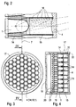
- FIG. 2 shows a detail of a lamp element on an enlarged scale.
- the light-emitting diode 1 as the light source is inserted in a corresponding socket with an electrical connection on the bottom.
- the lens 4 which in this example is designed as a lens body running over a plurality of light-emitting diodes.
- the optical beam path 6 runs according to FIG. 1 in a horizontal line through the light-emitting diode 1 and lens 4.
- an enveloping body 14 which surrounds the light-emitting diode 1 relatively closely in the lower region and approximately in the region of the object plane 7 in a slightly conical opening is shaped.
- the enveloping body 14 ends axially at a short distance in front of the light-emitting diode 1.
- a tubular element 15 is placed flush on the front side of the enveloping body 14 and its front end side stands up on the lens body 4.
- the envelope body 14 and the tubular element 15 can also be designed as a one-piece envelope element.
- the light rays 16 emanating from the light-emitting diode 1 run almost radially in the lower region of the light-emitting diode and hit the inner surface of the enveloping body 14. Since the surface of the enveloping body and also of the tubular element are designed in a non-reflecting manner, these light rays 16 are swallowed on the inner surface of the envelope.
- the light rays 16 emerge at a constantly decreasing angle and hit the inner surfaces of the enveloping body 14 and the tubular element 15 without being reflected. Only the light rays 16 emerging in a limited spherical front region of the light-emitting diode 1 hit the lens 4 arranged at a distance unhindered and are emitted from there onto the image plane 5.
- This structure of the lamp element clearly shows that the stray light from the light-emitting diode 1 is swallowed, while only active light is transmitted to the lens in accordance with the aperture effect.
- the Lenses 4 and also the enveloping body 14 with the tubular elements 15 in Cross-section are hexagonal.
- This hexagonal cross section allows an immediate close arrangement of the lenses 4 or the enveloping body 14 in this way, in a relatively small overall cross section of the reading light 17 a large number of light-emitting diodes 1 with lenses 4 can be accommodated. Thereby the desired minimum number of light-emitting diodes 1 of approximately 60 light-emitting diodes to be built in.
- the individual lenses 4 or the enveloping body 14 and the tubular elements 15 other cross sections are also possible, for example square, round or triangular Cross sections. However, it must be accepted that the Number of LEDs 1 to be accommodated is smaller and that between the individual light emitting diodes 1 with lenses 4 cavities that cannot be filled remain.
- the reading lamp 17 has a bottom side Cover 18 provided.
- the cover 18 on the bottom side adjoins FIG Axial direction a tubular jacket 19 in which the disc-shaped receptacle 20 is used for the light emitting diodes 1.
- the LEDs 1 are with their Legs 21 in the receptacle 20 mechanically fixed and electrically connected used.
- the enveloping bodies 14 with the tubular ones attached at the front Elements The tubular elements 15 close to the integrally formed Lens body 4 on the face of an annular collar of the Jacket 19 is bordered.
- the essentially honeycomb formation and type order of the enveloping body 14 with the tubular elements 15 serves at the same time also for centering the light-emitting diodes 1, the main task of these enveloping bodies 14 and tubular elements 15, however, consists of light rays each single light emitting diode focused on the lenses 4 to send.
- the enveloping body 14 as a whole mechanical Centering for the light emitting diodes 1 and the tubular body as an aperture and to be seen as a spacer for the hexagonal lens body 4.
- the lenses 4 are usually parallel to each other. However, they can also be rotated or tilted just as well, thereby deflecting the light beams down to light beams which are aimed at a single center point.
- the light beams emerging from the multiplicity of light-emitting diodes 1 of the reading light 17 overlap to form a single, essentially round light spot.
- all the circles of the light-emitting diodes 1 with lens 4 that can be seen in the front view of the reading lamp 17 overlap in the image plane 5 to form a single common light spot.
- This mode of operation is achieved in that corresponding distance ratios from the light-emitting diode 1 to the lens 4 and to the image plane 5 at a focal length according to the above-mentioned formula of be respected.
- the light-emitting diode arranged in the center in the front view according to FIG. 3 with only slight side differences forms the same light spot as the light-emitting diode 1 provided on the outer edge in the front view of the reading lamp 17.
- only this active light from the light-emitting diodes also permits the reading of printed matter which is held approximately in the image plane 5.
- FIGS. 5, 6 and 7 show possible arrangements of the light sources or LEDs 1 shown in plan view.
- Figure 5 gives way to the top view from Figure 3 in that in Figure 5 square lens body or envelope 14 are shown. From the comparison of Figures 5 and 3 it can be seen that the hexagonal cross-sectional shape of the lens body 4 with enveloping bodies 14 a more compact Arrangement allows.
- the light emerging from the light-emitting diodes 1 was Imaged freely on an image plane 5 via lens body 4.
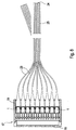
- the emerging from the individual light emitting diodes 1 in to couple as many light guides 23. So that each LED 1 as a light source the reading lamp 17 connected to a light guide 23. The light can come on are guided in this way over a relatively long distance to a light exit 24, which is designed as a flexible light guide end piece 25 and thereby for the Light exit has an adjustment range.
- the light guide 23 can over individual Coupling elements on the light emitting diodes 1 or with an overall coupling be plugged onto the LEDs 1.
- FIG. 9 shows the insertion of the light guides 23 onto the light-emitting diodes 1.
- the mounting of the light guide 23 in the enveloping bodies 14 can be done mechanically by clamping, friction or by gluing.
Abstract
Description
Die Erfindung betrifft eine Einrichtung zur Be- oder Ausleuchtung von Räumen,
Körpern oder Flächen nach dem Oberbegriff vom Patentanspruch 1.The invention relates to a device for illuminating or illuminating rooms,
Bodies or surfaces according to the preamble of
In der älteren und bisher nicht veröffentlichten deutschen Patentanmeldung DE 198 43 330.1 der Anmelderin ist eine Flugzeugkabinen-Beleuchtung beschrieben, die aus mehreren punktförmigen Lichtquellen besteht. Diese punktförmigen Lichtquellen weisen mindestens eine Leuchtdiode auf und sind an mindestens einer Stromversorgungseinheit angeschlossen. Durch die Anordnung mehrerer punktförmiger Lichtquellen an oder in der Decke der Kabine eines Luftfahrzeuges wird eine gleichmäßige Ausleuchtung der Kabine erreicht. Der Einsatz von Leuchtdioden in den punktförmigen Lichtquellen macht eine aufwendige elektrische Ansteuerung der Kabinenbeleuchtung überflüssig. Ferner ist gegenüber der Verwendung von üblichen Glühbirnen der Stromverbrauch erheblich geringer. Und schließlich ist die Lebensdauer von Leuchtdioden bekanntlich um ein vielfaches höher als die Lebensdauer von Leuchtstoffröhren oder Glühbirnen, so daß ein aufwendiges Auswechseln von defekten Leuchten nicht mehr nötig ist. In dieser älteren Patentanmeldung wurde auch bereits beschrieben, daß je nach der Dichte der an der Decke der Flugzeugkabine angeordneten punktförmigen Lichtquellen die Beleuchtung als Leselampe über einzelnen Sitzplätzen Verwendung finden kann. Für die Leuchtdioden sind vorzugsweise weiße Leuchtdioden vorgesehen, bei denen es sich aus zwei- oder mehrfarbigen Leuchtdioden gebildete Einheiten oder aus sogenannten Lumineszenskonversions-Dioden handeln kann.In the older and previously unpublished German patent application DE 198 43 330.1 of the applicant describes aircraft cabin lighting, which consists of several point light sources. These punctiform Light sources have at least one light-emitting diode and are on at least connected to a power supply unit. By arranging several punctiform light sources on or in the ceiling of the cabin of an aircraft uniform illumination of the cabin is achieved. The use of Light-emitting diodes in the punctiform light sources make an elaborate electrical Control of the cabin lighting is unnecessary. Furthermore, compared to the Using standard light bulbs the electricity consumption is considerably lower. And finally, the lifespan of LEDs is known to be many times longer longer than the lifespan of fluorescent tubes or light bulbs, so that a time-consuming replacement of defective lights is no longer necessary. In this Older patent applications have also been described, depending on the density the point-shaped light sources arranged on the ceiling of the aircraft cabin the lighting can be used as a reading lamp above individual seats can. White light-emitting diodes are preferably provided for the light-emitting diodes, which are units formed from two-colored or multi-colored light-emitting diodes or can act from so-called luminescence conversion diodes.
Der Einsatz von Leuchtdioden findet auch in der Verkehrstechnik vielfache Anwendung. So geht beispielsweise aus der DE 195 14 424 A1 hervor, zu zwei unterschiedlichen Lichtquellen kompatible Linsen für die Leuchte eines Fahrzeuges einzusetzen. Dabei handelt es sich um eine Kraftfahrzeugbegrenzungsleuchte mit einer Linse, die sowohl für die Ausleuchtung mit Leuchtdioden als auch mit Glühbirnen geschaffen wurde. Die Linse wurde deshalb so ausgebildet, daß sie einen Satz von Stufen für jede der unterschiedlichen Lichtquellen aufweist, um eine angestrebte Streuung der Lichtquelle zu bewirken. Insgesamt ist zu dieser Offenlegungsschrift festzuhalten, daß sie lediglich eine Begrenzungsleuchte darstellt, d. h., daß nur so viel Licht abgegeben wird, um eine Begrenzung eines Fahrzeugs durch die Rückleuchten zu erkennen. Eine Be- oder Ausleuchtung einer Fläche oder eines Körpers wird mit dieser offenbarten Leuchte nicht angestrebt, weshalb diese Leuchte dem Gebiet der passiven Leuchten zugeordnet werden kann.The use of LEDs is also widely used in traffic engineering. For example, DE 195 14 424 A1 shows two different ones Lenses compatible lenses for the light of a vehicle to use. It is a motor vehicle position lamp with a lens that can be used for both light-emitting diodes and light bulbs was created. The lens was therefore designed to be one Set of stages for each of the different light sources has a desired one To cause scattering of the light source. Overall, this disclosure is note that it is only a position lamp, d. H., that only so much light is emitted to limit a vehicle to recognize the taillights. Illumination or illumination of a surface or area Body is not aimed at with this disclosed lamp, which is why this Luminaire can be assigned to the area of passive luminaires.
Die WO 97/26483 offenbart eine Leuchtdiodenlampen-Vorrichtung für den Einsatz in Signallampen bzw. Verkehrsampeln. Auch in dieser Veröffentlichung geht es im Prinzip darum, ein ausreichendes Licht in verschiedenen Farben zur Verfügung zu stellen, um deutlich erkannt zu werden. Zu diesem Zweck sind mehrere Reihen von Leuchtdioden angeordnet worden, die durch eine Linse mit entsprechenden Stufen abgedeckt werden. Durch diese Abstufungen in der Linse wird erreicht, daß das Licht unter bestimmten Winkeln zur Strahlenachse ausgesendet wird, um dadurch aus verschiedenen Winkeln und allen Witterungseinflüssen gut sichtbar zu sein.WO 97/26483 discloses a light emitting diode device for use in signal lamps or traffic lights. This publication is also about Principle about having enough light available in different colors in order to be clearly recognized. For this purpose there are several rows of LEDs have been arranged through a lens with appropriate steps be covered. Through these gradations in the lens it is achieved that Light is emitted at certain angles to the beam axis, thereby to be clearly visible from different angles and all weather influences.
Die EP 0 523 927 B1 beschreibt eine Leuchtstofflampe mit Linse. Dabei ist dieser Veröffentlichung als wesentlich zu entnehmen, daß ein Linsenelement für eine Leuchtdiode mindestens zwei Fassetten, d. h. Linsenkörper aufweist. Durch die Fassetten wird durch Brechung ein gewünschter Ausgangsstrahl geformt.EP 0 523 927 B1 describes a fluorescent lamp with a lens. Here is this Publication as essential that a lens element for a LED at least two facets, d. H. Has lens body. Through the A desired output beam is formed by refraction of the facets.
Ausgehend von dem vorgenannten Stand der Technik ist es Aufgabe der Erfindung, eine Einrichtung zur Be- oder Ausleuchtung von Räumen, Körpern oder Flächen zu schaffen, durch welche in einem einstellbaren Abstand von der Lichtquelle eine relativ schaff gegen die Umgebung abgegrenzte, hell erleuchtete Fläche erzielt wird, die als aktives Licht bezeichnet wird.Starting from the aforementioned prior art, it is the object of the invention a device for illuminating or illuminating rooms, bodies or Create surfaces through which at an adjustable distance from the light source a relatively well-lit area delineated from the surroundings is achieved, which is referred to as active light.
Erfindungsgemäß ist diese Aufgabe durch die Merkmale des Patentanspruchs 1
gelöst. Vorteilhafte Ausgestaltungen und Weiterbildungen der Erfindung sind in
den Unteransprüchen beschrieben. According to the invention, this object is achieved by the features of
Mit dieser erfinderischen Lösung wird eine Leseleuchte auf der Basis von Leuchtdioden (LEDs) für die Verwendung insbesondere in der Luftfahrt geschaffen Eine solche neue Leseleuchte zeichnet sich durch eine hohe Ausfallsicherheit aus. Es wird ein maximales Licht aus den Leuchtdioden nach vorne zur auszuleuchtenden Fläche erzielt. Wegen der hohen Zuverlässigkeit der Leuchtdioden entfällt der bei üblichen Leuchtmitteln häufige Wechsel. Ferner bietet die Lösung für Leseleuchten Gestaltungsfreiräume und variable konstruktive Auslegungen. Weitere Vorteile sind:
- Es wird eine relativ scharfkantige Abbildung des Lichtkreises erzielt.
- Der Lichtausgang ist proportional zu der Menge der Leuchtdioden.
- In Versuchen mit anschließenden Messungen hat sich herausgestellt, daß eine Menge von 60 Leuchtdioden für eine Leseleuchte optimale Ergebnisse bringt, jedoch sind auch geringere Mengen und größere Mengen mit Erfolg einsetzbar
- Es sind schmale Leuchten möglich, die dennoch einen ausreichend großen Lichtfleck erzeugen.
- A relatively sharp-edged image of the light circle is achieved.
- The light output is proportional to the amount of light emitting diodes.
- Experiments with subsequent measurements have shown that a quantity of 60 light-emitting diodes brings optimum results for a reading light, but smaller quantities and larger quantities can also be used successfully
- Narrow lights are possible, which nevertheless generate a sufficiently large light spot.
In der Zeichnung sind Beispiele der Erfindung dargestellt. Es zeigen:
Figur 1- eine schematische Darstellung des theoretischen Modells für den optischen Strahlengang einer Leseleuchte,
- Figur 1a
- eine Frontansicht der Linse im Detail,
Figur 2- ein Leuchtenelement im Längsschnitt,
- Figur 3
- eine Draufsicht auf eine Leseleuchte mit Leuchtelementen,
Figur 4- die Leseleuchte nach Figur 3 gemäß der Linie IV-IV im Schnitt,
Figur 5- die Vorderansicht einer Leseleuchte mit anderer Anordnung von Leuchtelementen,
Figur 6- eine weitere Vorderansicht einer Leseleuchte mit anders angeordneten Leuchtelementen,
Figur 7- eine wiederum weitere Vorderansicht einer Leseleuchte mit anders angeordneten Leuchtelementen,
Figur 8- eine Leseleuchte im Schnitt mit angekoppelten Lichtleitern,
Figur 9- ein einzelnes Leuchtelement mit angekoppeltem Lichtleiter im Schnitt.
- Figure 1
- 1 shows a schematic representation of the theoretical model for the optical beam path of a reading lamp,
- Figure 1a
- a front view of the lens in detail,
- Figure 2
- a lamp element in longitudinal section,
- Figure 3
- a plan view of a reading lamp with lighting elements,
- Figure 4
- 3 according to the line IV-IV in section,
- Figure 5
- the front view of a reading lamp with a different arrangement of lighting elements,
- Figure 6
- another front view of a reading lamp with differently arranged lighting elements,
- Figure 7
- a further front view of a reading lamp with differently arranged lighting elements,
- Figure 8
- an average reading light with coupled light guides,
- Figure 9
- a single light element with a coupled light guide on average.
In dem theoretischen Modell zur Darstellung des optischen Strahlenganges für eine
Leseleuchte ist die Lichtquelle mit 1 bezeichnet, die gemäß der Erfindung eine
Leuchtdiode ist. Die Leuchtdiode 1 besitzt eine vordere, im wesentlichen kugelförmige
Lichtaustrittsfläche 2. In vorteilhafter Anwendung der Erfindung werden
bevorzugt eng fokussierende Leuchtdioden 1 (LED) eingesetzt. In einem wählbaren
und einstellbaren Abstand zur Objektebene 7 der Leuchtdiode 1 befindet sich in
einer Hauptebene 3 eine Linse 4. In einem weiteren einstellbaren Abstand vor dieser
Linse 4 mit der Hauptebene 3 ist die Bildebene 5 dargestellt, die ebenso wie die
Hauptebene 3 senkrecht zum optischen Strahlengang 6 angeordnet ist. Der Abstand
zwischen der Objektebene 7 der Leuchtdiode 1 und der Hauptebene 3 der
Linse 4 ist mit S0 bezeichnet, während der Abstand zwischen der Hauptebene 3 der
Linse 4 und der Bildebene 5 das Bezugszeichen S1 trägt. Die Abstände S0 zu S1
verhalten sich im Beispielsfall etwa wie 100 : 1. Das Verhältnis ist abhängig von
der auszuleuchtenden Fläche in der Bildebene 5.In the theoretical model for representing the optical beam path for a reading lamp, the light source is designated by 1, which according to the invention is a light-emitting diode. The light-emitting
Der optische Strahlengang 6 verläuft ausgehend von der Lichtquelle 1 durch die
Linse 4 bis auf die Bildebene 5 in einer durchgehenden, hier waagerecht gezeichneten
Ebene. Die am Außenumfang der Leuchtdiode 1 austretenden Lichtstrahlen 8
verlaufen bis zum Eintritt in die Hauptebene 3 der Linse 4 parallel zum optischen
Strahlengang 6. Die Lichtstrahlen 8 werden in der Linse 4 entsprechend den optischen
Gesetzen umgelenkt und treffen in einem gleichmäßigen radialen Abstand
von dem optischen Strahlengang 6 auf die Bildebene 5 auf und markieren auf der
Bildebene 5 dadurch in einem entsprechend vergrößertem Maßstab die Lichtquelle
ab. Dies bedeutet, daß auf der Bildebene 5 der optische Strahlengang im Punkt 9
auftrifft, und die beiden abgelenkten Strahlen 8 markieren auf der Bildebene 5 jeweils
die äußeren Punkte 10, deren Abstand zueinander den Durchmesser der abgebildeten
Lichtquelle auf der Bildebene 5 darstellt. Der parallel zum optischen
Strahlengang 6 verlaufende Lichtstrahl 8 tritt am Punkt 11 aus der Objektebene der
Strahlengang 6 verlaufende Lichtstrahl 8 tritt am Punkt 11 aus der Objektebene der
Leuchtdiode 1 aus. Vom gleichen Punkt 11 auf der Objektebene wird der optische
Strahl 12 abgenommen, der durch die Mitte der Linse 4 verläuft und auf der Bildebene
5 wiederum exakt im Punkt 10 endet. Der dritte Lichtstrahl 13 vom Ausgangspunkt
11 trifft im unteren Randbereich der Linse 4 ein und wird dergestalt
abgelenkt, daß er ebenfalls im Punkt 10 der Bildebene auftrifft. Die Lichtstrahlen 8,
12, 13 mit dem Ausgangspunkt 11 und dem Auftreffpunkt 10 unterliegen der Bedingung,
daß

Auf der Bildebene wird die Lichtquelle, nämlich die Leuchtdiode 1, abgebildet.
Entsprechend den im Beispielsfall vorgegebenen Verhältnissen des Abstandes S1
zum Abstand S0 beträgt der Abbildungsmaßstab der Lichtquelle auf der LED-Linse
etwa 10 : 1, wahrend der Abbildungsmaßstab für die Lichtquelle in der Bildebene 5
etwa 10 : 1 ist.The light source, namely the light-emitting
Entsprechend dem Detail in Figur 1a ist die Linse 4 vorzugsweise in eine Fassung
von hexagonalem Querschnitt eingesetzt.According to the detail in Figure 1a, the
In Figur 2 ist ein Detail eines Leuchtenelementes in vergrößertem Maßstab dargestellt.
Die Leuchtdiode 1 als Lichtquelle ist bodenseitig in eine entsprechende Fassung
mit elektrischem Anschluß eingesetzt. Im Abstand S0 von der Objektebene 7
befindet sich wieder die Linse 4, die in diesem Beispiel als ein über mehrere
Leuchtdioden verlaufender Linsenkörper ausgebildet ist. Der optische Strahlengang
6 verläuft entsprechend der Figur 1 in waagerechter Linie durch die Leuchtdiode
1 und Linse 4. Um die Leuchtdiode ist ein Hüllkörper 14 angeordnet, der die
Leuchtdiode 1 im unteren Bereich relativ eng umschließt und etwa im Bereich der
Objektebene 7 in leichter konischer Öffnung geformt ist. Der Hüllkörper 14 endet
in geringem Abstand axial vor der Leuchtdiode 1. Auf den Hüllkörper 14 ist ein
röhrenförmiges Element 15 stirnseitig bündig aufgesetzt, das mit seiner vorderen
Stirnseite auf dem Linsenkörper 4 aufsteht. Der Hüllkörper 14 und das röhrenförmige
Element 15 können auch als einstückiges Hüllelement ausgebildet sein. Wie
aus Figur 2 ersichtlich ist, verlaufen die von der Leuchtdiode 1 ausgehenden
Lichtstrahlen 16 im unteren Bereich der Leuchtdiode nahezu radial und treffen auf
die Innenfläche des Hüllkörpers 14. Da die Oberfläche des Hüllkörpers und auch
des röhrenförmigen Elementes in nicht-reflektierender Weise ausgebildet sind,
werden diese Lichtstrahlen 16 auf der Innenfläche des Hüllkörpers geschluckt. Im
oberen kugelförmigen Abschnitt der Leuchtdiode treten die Lichtstrahlen 16 und
einem ständig geringer werdenden Winkel aus und treffen dort auf die Innenflächen
des Hüllkörpers 14 und des röhrenförmigen Elementes 15, ohne reflektiert zu werden.
Nur die in einem begrenzten kugelförmigen Frontbereich der Leuchtdiode 1
austretenden Lichtstrahlen 16 treffen ungehindert auf die im Abstand angeordnete
Linse 4 und werden von dort auf die Bildebene 5 abgestrahlt. Dieser Aufbau des
Leuchtenelementes zeigt deutlich, daß das Streulicht der Leuchtdiode 1 geschluckt
wird, während entsprechend der Blendenwirkung nur aktives Licht zur Linse
durchgegeben wird.FIG. 2 shows a detail of a lamp element on an enlarged scale. The light-emitting
Aus der Vorderansicht der Leseleuchte 17 nach Figur 3 ist zu erkennen, daß die
Linsen 4 und auch die Hüllkörper 14 mit den röhrenförmigen Elementen 15 im
Querschnitt sechseckförmige ausgebildet sind. Dieser hexagonale Querschnitt erlaubt
eine unmittelbare enge Anordnung der Linsen 4 bzw. der Hüllkörper 14. Auf
diese Weise kann in einem relativ kleinen Gesamtquerschnitt der Leseleuchte 17
eine Vielzahl von Leuchtdioden 1 mit Linsen 4 untergebracht werden. Dadurch
wird die angestrebte Mindestzahl von Leuchtdioden 1 von etwa 60 Stück Leuchtdioden
eingebaut werden. Natürlich sind statt der hexagonalen Querschnitte der
einzelnen Linsen 4 bzw. der Hüllkorper 14 und der röhrenförmigen Elemente 15
auch andere Querschnitte möglich, beispielsweise quadratische, runde oder dreieckförmige
Querschnitte. Dabei muß jedoch in Kauf genommen werden, daß die
Anzahl der unterzubringenden Leuchtdioden 1 geringer wird und daß zwischen den
einzelnen Leuchtdioden 1 mit Linsen 4 nicht ausfüllbare Hohlräume verbleiben.From the front view of the reading
Die Leseleuchte 17 ist gemäß der Schnittdarstellung in Figur 4 mit einer bodenseitigen
Abdeckung 18 versehen. An die bodenseitige Abdeckung 18 schließt sich in
axialer Richtung ein röhrenförmiger Mantel 19 an, in den die scheibenförmige Aufnahme
20 für die Leuchtdioden 1 eingesetzt ist. Die Leuchtdioden 1 sind mit ihren
Anschlußbeinchen 21 in die Aufnahme 20 mechanisch fest und elektrisch verbunden
eingesetzt. Entsprechend der Detaildarstellung nach Figur 2 befinden sich um
die Leuchtdioden 1 die Hüllkörper 14 mit den frontseitig angesetzten röhrenförmigen
Elementen Die röhrenförmige Elemente 15 schließen an den einstückig ausgebildeten
Linsenkörper 4 stirnseitig an, der von einem ringförmigen Kragen des
Mantels 19 eingefaßt ist. Die im wesentlichen wabenförmige Ausbildung und An
ordnung der Hüllkörper 14 mit den röhrenförmigen Elementen 15 dient gleichzeitig
auch zur Zentrierung der Leuchtdioden 1, wobei die Hauptaufgabe dieser Hüllkörper
14 und röhrenförmige Elemente 15 jedoch darin besteht, die Lichtstrahlen jeder
einzelnen Leuchtdiode konzentriert auf die Linsen 4 zu senden. In dem Aufbau der
Leseleuchte 17 nach Figur 4 sind die Hüllkörper 14 insgesamt als mechanische
Zentrierung für die Leuchtdioden 1 und die röhrenförmigen Körper als Blende und
als Distanzscheibe für die hexagonalen Linsenkörper 4 zu sehen.According to the sectional view in FIG. 4, the reading
Die Linsen 4 liegen normalerweise parallel nebeneinander. Sie können ebenso gut
jedoch auch gedreht oder gekippt werden, wodurch ein Ablenken der Lichtstrahlen
erzielt wird bis hin zu Lichtstrahlen, die auf einen einzigen Mittelpunkt ausgerichtet
sind. Aufgrund der in Figur 1 erläuterten Verhältnisse überlagern sich die aus der
Vielzahl von Leuchtdioden 1 der Leseleuchte 17 austretenden Lichtstrahlen zu
einem einzigen, im wesentlichen runden Lichtfleck. Mit anderen Worten, alle in der
Vorderansicht der Leseleuchte 17 zu erkennenden Kreise der Leuchtdioden 1 mit
Linse 4 überlagern sich in der Bildebene 5 zu einem einzigen gemeinsamen Lichtfleck.
Diese Wirkungsweise wird dadurch erzielt, daß entsprechende Abstandsverhältnisse
von der Leuchtdiode 1 zur Linse 4 und zur Bildebene 5 bei einer Brennweite
nach der oben bereits erwähnten Formel von
![]()
![]()
In den Figuren 5, 6 und 7 sind mögliche Anordnungen der Lichtquellen bzw.
Leuchtdioden 1 in der Draufsicht dargestellt. Die Figur 5 weicht in der Draufsicht
von Figur 3 dadurch ab, daß in Figur 5 quadratisch Linsenkörper bzw. Hüllkörper
14 dargestellt sind. Aus dem Vergleich der Figuren 5 und 3 ist erkennbar, daß die
hexagonale Querschnittsform der Linsenkörper 4 mit Hüllkörpern 14 eine kompaktere
Anordnung zuläßt.FIGS. 5, 6 and 7 show possible arrangements of the light sources or
In Figur 6 sind zwei Frontansichten von Leseleuchten dargestellt, die beide rechteckförmig
sind, jedoch unterschiedliche Längen- und Breitenverhältnisse aufweisen.
Trotz dieser im Rechteck aneinander gefügten Lichtquellen 1 erscheint auf der
Bildebene 5 ein im wesentlichen gleicher, runder Lichtfleck, weil alle einzelnen
Lichtflecke aus den Leuchtdioden aufgrund der in Figur 1 geschilderten Verhältnisse
sich zu einem einzigen Lichtfleck auf der Bildebene 5 überlagern.In Figure 6, two front views of reading lights are shown, both rectangular
are, but have different length and width ratios.
Despite these
Auch in den beiden in Figur 7 dargestellten Beispielen werden mit den in der
Frontansicht kreisringförmigen bzw. nierenförmigen Leseleuchten auf der Bildebene
5 runde Lichtpunkte bzw. Lichtflecke erzielt.Also in the two examples shown in Figure 7 with the in the
Front view of circular or kidney-shaped reading lights on the
Nach den Figuren 1 bis 7 wurde das aus den Leuchtdioden 1 austretende Licht
über Linsenkörper 4 frei auf eine Bildebene 5 abgebildet. Nach Figur 8 ist es aber
auch ebenso möglich, das aus den einzelnen Leuchtdioden 1 austretende Licht in
ebenso viele Lichtleiter 23 einzukoppeln. Damit wird jede Leuchtdiode 1 als Lichtquelle
der Leseleuchte 17 mit einem Lichtleiter 23 verbunden. Das Licht kann auf
diese Weise über eine relativ lange Strecke zu einem Lichtaustritt 24 geleitet werden,
der als ein flexibles Lichtleiterendstück 25 ausgebildet ist und dadurch für den
Lichtaustritt einen Verstellbereich aufweist. Die Lichtleiter 23 können über einzelne
Koppelelemente auf die Leuchtdioden 1 oder aber mit einer Gesamtkupplung
auf die Leuchtdioden 1 aufsteckbar sein.According to FIGS. 1 to 7, the light emerging from the light-emitting
In Figur 9 ist das Aufstecken der Lichtleiter 23 auf die Leuchtdioden 1 dargestellt.
Es handelt sich hier um die einzelnen Koppelelemente 26, die als aufgeweitete
Endstücke der Lichtleiter 23 ausgebildet sind und sich einerseits um den kugelförmigen
Kopf der Leuchtdiode 1 anlegen und andererseits in der Fassung des
Hüllkörpers 14 eng anliegen. Die Halterung der Lichtleiter 23 in den Hüllkörpern
14 kann mechanisch durch klemmen, Reibung oder durch kleben erfolgen.FIG. 9 shows the insertion of the light guides 23 onto the light-emitting
Claims (11)
dadurch gekennzeichnet,
daß jede der mehreren eine Leuchte (17) bildenden Leuchtdioden (1) von einem Körper (14,15) radial umhüllt ist, an dessen vordere freie, stirnseitige Lichtaustrittsöffnung ein Linsenkörper (4) derart eingesetzt ist, daß die Leuchtdiode (1), der Linsenkörper (4) und der im Abstand auf einen Körper oder eine Fläche auftreffende Lichtpunkt (10) auf einer optischen Achse (16) (Strahlengang) liegen.Device for illuminating or illuminating rooms, bodies or surfaces, in particular reading lights for aviation devices, from at least one light source in the form of a white light-emitting diode or a luminescence conversion diode which is connected to a power supply unit.
characterized,
that each of the several light-emitting diodes (1) forming a lamp (1) is radially enveloped by a body (14, 15), at the front free front light outlet opening of which a lens body (4) is inserted such that the light-emitting diode (1), Lens body (4) and the light spot (10) hitting a body or a surface at a distance lie on an optical axis (16) (beam path).
dadurch gekennzeichnet,
daß der Linsenkörper (4) im axialen Abstand (S0) vor der Leuchtdiode (1) angeordnet ist, der etwa 1/100 des Abstandes (S1) zwischen dem Linsenkörper (4) und der Auftreffebene für den Lichtpunkt ist.Device according to claim 1,
characterized,
that the lens body (4) is arranged at an axial distance (S 0 ) in front of the light-emitting diode (1), which is approximately 1/100 of the distance (S 1 ) between the lens body (4) and the plane of incidence for the light spot.
dadurch gekennzeichnet,
daß der Hüllkörper (14,15) röhrenförmig mit beliebiger geometrischer Querschnittsfläche ausgebildet ist, dessen Innenwände parallel zur Hüllkörperlängsachse bzw. zur optischen Achse (6) verlaufen.Device according to claim 1 or 2,
characterized,
that the enveloping body (14, 15) is tubular with any geometric cross-sectional area, the inner walls of which run parallel to the longitudinal axis of the enveloping body or to the optical axis (6).
dadurch gekennzeichnet,
daß der Hüllkörper (14,15) röhrenförmig mit beliebiger geometrischer Querschnittsfläche ausgebildet ist, dessen Innenwände abweichend von der Hüllkörperlangsachse konisch oder ballig verlaufen. Device according to claim 1 or 2,
characterized,
that the enveloping body (14, 15) is tubular with any geometric cross-sectional area, the inner walls of which deviate from the longitudinal axis of the enveloping body are conical or spherical.
dadurch gekennzeichnet,
daß der Hüllkörper (14,15) eine sechseckförmige Querschnittsfläche aufweist.Device according to one of the preceding claims,
characterized,
that the enveloping body (14, 15) has a hexagonal cross-sectional area.
dadurch gekennzeichnet,
daß der Hüllkörper (14,15) eine kreisförmige, quadratische oder dreieckförmige Querschnittsfläche aufweist.Device according to one of claims 1 to 4,
characterized,
that the enveloping body (14, 15) has a circular, square or triangular cross-sectional area.
dadurch gekennzeichnet,
daß der Hüllkörper (14,15) aus einem fußseitigen Zentrierteil (14) und einem kopfseitigen Blendenteil (15) gebildet ist, der am Linsenkörper (4) ansteht.Device according to one of claims 1 to 6,
characterized,
that the enveloping body (14, 15) is formed from a foot-side centering part (14) and a head-side diaphragm part (15) which bears against the lens body (4).
dadurch gekennzeichnet,
daß die Leuchte (17) aus einer Vielzahl von Leuchtdioden (1) mit Hüllkörpern (14,15) gebildet ist, die im Querschnitt hexagonal und wabenförmig aneinandergelegt sind.Device according to one of claims 1 to 7,
characterized,
that the lamp (17) is formed from a multiplicity of light-emitting diodes (1) with enveloping bodies (14, 15) which are arranged in a hexagonal and honeycomb cross-section.
dadurch gekennzeichnet,
daß die Linsenkörper (4) aus einem gemeinsamen Träger herausgeformt sind.Device according to one of claims 1 to 8,
characterized,
that the lens body (4) are formed from a common carrier.
dadurch gekennzeichnet,
daß die Linsenkörper (4) hexagonal ausgebildet sind.Device according to one of the preceding claims,
characterized,
that the lens body (4) are hexagonal.
dadurch gekennzeichnet,
daß die Hüllkörper (14) als Koppelelemente für Lichtleiter (23) ausgebildet sind.Device according to one of the preceding claims,
characterized,
that the enveloping body (14) are designed as coupling elements for light guides (23).
Applications Claiming Priority (2)
| Application Number | Priority Date | Filing Date | Title |
|---|---|---|---|
| DE19908040A DE19908040A1 (en) | 1999-02-24 | 1999-02-24 | Device for illuminating rooms, bodies or surfaces |
| DE19908040 | 1999-02-24 |
Publications (2)
| Publication Number | Publication Date |
|---|---|
| EP1031464A2 true EP1031464A2 (en) | 2000-08-30 |
| EP1031464A3 EP1031464A3 (en) | 2003-07-09 |
Family
ID=7898749
Family Applications (1)
| Application Number | Title | Priority Date | Filing Date |
|---|---|---|---|
| EP00103113A Withdrawn EP1031464A3 (en) | 1999-02-24 | 2000-02-16 | Device for the illumination of a room, a body or a surface |
Country Status (3)
| Country | Link |
|---|---|
| US (1) | US6520666B1 (en) |
| EP (1) | EP1031464A3 (en) |
| DE (1) | DE19908040A1 (en) |
Cited By (4)
| Publication number | Priority date | Publication date | Assignee | Title |
|---|---|---|---|---|
| EP1496380A1 (en) * | 2003-07-09 | 2005-01-12 | Diehl Luftfahrt Elektronik GmbH | Lighting element with LED |
| EP1767967A2 (en) | 2005-09-26 | 2007-03-28 | Osram Sylvania Inc. | Led lamp with direct optical coupling to an optical light guide having purality of light pipes in axial arrangement |
| AT513917A1 (en) * | 2013-02-05 | 2014-08-15 | Zizala Lichtsysteme Gmbh | Lighting unit for a headlight and headlights |
| WO2018069175A1 (en) * | 2016-10-11 | 2018-04-19 | HELLA GmbH & Co. KGaA | Lighting device for a vehicle |
Families Citing this family (48)
| Publication number | Priority date | Publication date | Assignee | Title |
|---|---|---|---|---|
| DE19926561A1 (en) | 1999-06-11 | 2000-12-14 | Diehl Stiftung & Co | Spotlights, in particular reading lights in the cabins of vehicles |
| DE20019923U1 (en) * | 2000-11-23 | 2002-01-10 | Siemens Ag | Construction system for mounting LED modules and LED module for mounting in a construction system |
| DE10131686A1 (en) * | 2001-06-29 | 2003-01-16 | Mellert Fa Hermann | flashlight |
| US6871981B2 (en) * | 2001-09-13 | 2005-03-29 | Heads Up Technologies, Inc. | LED lighting device and system |
| DE10147235A1 (en) * | 2001-09-26 | 2003-04-30 | Kastriot Merlaku | Camera flash light with LEDs consists of at least one visible intensive white light emitting LED or several LEDs emitting different colors to give almost white light in combination |
| DE10147236A1 (en) * | 2001-09-26 | 2003-04-30 | Kastriot Merlaku | Video light for video camera with LEDs consists of at least one visible intensive white light emitting LED or several LEDs emitting different colors to give almost white light in combination |
| JP3984023B2 (en) * | 2001-11-02 | 2007-09-26 | 株式会社小糸製作所 | Vehicle lamp |
| DE10204939A1 (en) * | 2002-02-07 | 2003-09-04 | Parsytec Comp Gmbh | Device for generating flat parallel light has two adjacent lenses in plane perpendicular to main radiation direction, illuminated in 2-D by one of two point sources, parallel in at least one dimension |
| DE10208109B4 (en) * | 2002-02-26 | 2006-04-13 | Kastriot Merlaku | Interior lighting system for a helicopter |
| DE10208111B4 (en) * | 2002-02-26 | 2006-04-13 | Kastriot Merlaku | Interior lighting system for an aircraft |
| US20030189836A1 (en) * | 2002-04-04 | 2003-10-09 | Sparling Teddy Burch | Boat trailer employing immersible fiber-optic lighting means |
| JP3619850B2 (en) * | 2002-04-08 | 2005-02-16 | 株式会社キャットアイ | Bicycle headlamp |
| JP2004047351A (en) * | 2002-07-15 | 2004-02-12 | Koito Mfg Co Ltd | Vehicular lighting fixture |
| US7334918B2 (en) * | 2003-05-07 | 2008-02-26 | Bayco Products, Ltd. | LED lighting array for a portable task light |
| US20050128761A1 (en) * | 2003-12-10 | 2005-06-16 | Shih-Hsiung Wu | Turn signal light using light-emitting diodes as light sources |
| US7097336B2 (en) * | 2004-05-28 | 2006-08-29 | Yu-Chu Lin | Auxiliary light ring device for a vehicular light |
| US7070311B2 (en) * | 2004-06-03 | 2006-07-04 | Fu An Industrial Co., Ltd. | Vehicle light for producing light whose form depends on orientations of plural refraction elements |
| DE102004031858A1 (en) * | 2004-07-01 | 2006-01-19 | Automotive Lighting Reutlingen Gmbh | Lens arrangement and motor vehicle headlight or motor vehicle lamp with such a lens arrangement |
| CA2576064C (en) * | 2004-07-20 | 2013-06-25 | Torrero Technologies | Bicycle lighting system |
| US20060075666A1 (en) * | 2004-10-07 | 2006-04-13 | Robbie Thielemans | Display and corresponding support, emissive lighting display modules and packaging for such display modules |
| JP4050271B2 (en) * | 2004-12-07 | 2008-02-20 | シャープ株式会社 | Objective lens holder, objective lens driving apparatus including the same, and optical disc recording / reproducing apparatus |
| US20070035955A1 (en) * | 2005-01-27 | 2007-02-15 | Airbus Deutschland Gmbh | Light for use for a passenger seat |
| US20060268548A1 (en) * | 2005-05-25 | 2006-11-30 | Haoli Precision Industrial Co., Ltd. | LED lighting device with light converging effect |
| KR20080039871A (en) * | 2005-07-12 | 2008-05-07 | 마그나 인터내셔널 인코포레이티드 | Semiconductor light engine for automotive lighting |
| US20070121333A1 (en) * | 2005-11-30 | 2007-05-31 | Ronald Woodward | Semiconductor light engine for automotive lighting |
| US20070225778A1 (en) * | 2006-03-23 | 2007-09-27 | Heacock Gregory L | PDT apparatus with an addressable LED array for therapy and aiming |
| US7566154B2 (en) * | 2006-09-25 | 2009-07-28 | B/E Aerospace, Inc. | Aircraft LED dome light having rotatably releasable housing mounted within mounting flange |
| DE202006016879U1 (en) * | 2006-11-04 | 2008-03-13 | Alfavision Gmbh & Co. Kg | Modular measuring scanner |
| WO2008070607A1 (en) * | 2006-12-04 | 2008-06-12 | Cree Led Lighting Solutions, Inc. | Lighting assembly and lighting method |
| DE102007017343B4 (en) | 2007-04-12 | 2010-05-12 | Airbus Deutschland Gmbh | Reading light with stray light suppression |
| US7635213B2 (en) * | 2008-02-07 | 2009-12-22 | Ching-Liang Lee | Vehicle light assembly |
| US8430526B2 (en) * | 2008-08-29 | 2013-04-30 | Northrop Grumman Systems Corporation | Method and apparatus for producing a uniform irradiance distribution from an array of light emitting diodes |
| US20100097803A1 (en) * | 2008-10-20 | 2010-04-22 | Wu Ming-Chang | Multiple Light Source Surface Packaging Structure |
| TW201040447A (en) * | 2009-03-13 | 2010-11-16 | Koninkl Philips Electronics Nv | Pattern-projecting light-output system |
| DE202009006261U1 (en) * | 2009-04-29 | 2010-09-16 | Zumtobel Lighting Gmbh | LED light |
| WO2010147414A2 (en) * | 2009-06-17 | 2010-12-23 | Lg Chem, Ltd. | Light extraction member and organic light emitting diode including the same |
| TWI426302B (en) * | 2010-02-12 | 2014-02-11 | Au Optronics Corp | Display device and light enhancement film of the display device |
| US8348484B2 (en) * | 2010-04-22 | 2013-01-08 | Ford Global Technologies, Llc | Vehicle exterior lamp |
| DE102010039859A1 (en) * | 2010-08-27 | 2012-03-01 | Osram Ag | Reading light for motor vehicles |
| US9343002B2 (en) * | 2011-08-19 | 2016-05-17 | Luminator Holding L.P. | Window including integrated display signage |
| US8608344B2 (en) * | 2011-09-06 | 2013-12-17 | Asia Vital Components Co., Ltd. | LED lighting structure |
| US9500340B2 (en) | 2011-10-25 | 2016-11-22 | A-Dec, Inc. | Dental light using LEDs |
| DE102011085978A1 (en) * | 2011-11-09 | 2013-05-16 | Osram Gmbh | LASER FLASH DEVICE WITH LASER ARRAY |
| US8899786B1 (en) * | 2012-05-04 | 2014-12-02 | Cooper Technologies Company | Method and apparatus for light square assembly |
| US10384803B2 (en) * | 2016-10-07 | 2019-08-20 | The Boeing Company | Methods and devices for light distribution in an aircraft, and aircraft including such devices |
| KR101937974B1 (en) * | 2018-05-08 | 2019-01-14 | 주식회사 에이엘테크 | Light emitting sign apparatus using optical fiber |
| EP3647654A1 (en) * | 2018-10-31 | 2020-05-06 | Valeo Iluminacion, S.A. | Automotive lighting device |
| EP3956925A1 (en) * | 2019-04-18 | 2022-02-23 | Lumileds Holding B.V. | Lighting device |
Citations (5)
| Publication number | Priority date | Publication date | Assignee | Title |
|---|---|---|---|---|
| US4935665A (en) * | 1987-12-24 | 1990-06-19 | Mitsubishi Cable Industries Ltd. | Light emitting diode lamp |
| EP0523927A2 (en) * | 1991-07-17 | 1993-01-20 | Precision Solar Controls Inc | LED lamp including refractive lens element |
| EP0596866A2 (en) * | 1990-12-22 | 1994-05-11 | Stanley Electric Co., Ltd. | Light irradiating apparatus having light emitting diode used as light source |
| US5490049A (en) * | 1993-07-07 | 1996-02-06 | Valeo Vision | LED signalling light |
| DE29811417U1 (en) * | 1998-02-13 | 1998-10-08 | Hohe Gmbh & Co Kg | Lighting device for motor vehicles |
Family Cites Families (15)
| Publication number | Priority date | Publication date | Assignee | Title |
|---|---|---|---|---|
| DE2930383C2 (en) * | 1979-07-26 | 1983-01-20 | Optische Werke G. Rodenstock, 8000 München | LED arrangement |
| US4733335A (en) * | 1984-12-28 | 1988-03-22 | Koito Manufacturing Co., Ltd. | Vehicular lamp |
| US4754380A (en) * | 1987-04-13 | 1988-06-28 | Wang Tien D | Characters for illuminated display signs |
| US4903175A (en) * | 1988-11-30 | 1990-02-20 | Mcdonnell Douglas Corporation | Illumination module |
| FR2697485B1 (en) * | 1992-11-02 | 1995-01-20 | Valeo Vision | Signaling light with modular luminous elements, for a motor vehicle. |
| US5325275A (en) * | 1993-04-22 | 1994-06-28 | Liu Hui Long | Angle adjustable car reading lamp |
| US5388035A (en) * | 1993-07-23 | 1995-02-07 | Federal-Mogul Corporation | Automotive marker lamp |
| US5508897A (en) * | 1994-04-01 | 1996-04-16 | Prince Corporation | Overhead lamp assembly |
| GB2288658B (en) | 1994-04-19 | 1998-04-22 | Koito Mfg Co Ltd | Vehicular marker lamp lens compatible with two different kinds of light sources |
| DE4439547A1 (en) * | 1994-11-05 | 1996-05-09 | Hella Kg Hueck & Co | Internal lighting system for motor vehicle |
| US5671996A (en) * | 1994-12-30 | 1997-09-30 | Donnelly Corporation | Vehicle instrumentation/console lighting |
| US5669698A (en) * | 1995-05-24 | 1997-09-23 | Veldman; Roger L. | Modular rearview mirror assembly and method for making same |
| WO1997026483A1 (en) | 1996-01-17 | 1997-07-24 | Dialight Corporation | An led illuminated lamp assembly |
| DE19610138C2 (en) * | 1996-03-15 | 2000-07-13 | Daimler Chrysler Aerospace | Reading lamp system for a passenger plane |
| US6152590A (en) * | 1998-02-13 | 2000-11-28 | Donnelly Hohe Gmbh & Co. Kg | Lighting device for motor vehicles |
-
1999
- 1999-02-24 DE DE19908040A patent/DE19908040A1/en not_active Ceased
-
2000
- 2000-02-01 US US09/495,990 patent/US6520666B1/en not_active Expired - Fee Related
- 2000-02-16 EP EP00103113A patent/EP1031464A3/en not_active Withdrawn
Patent Citations (5)
| Publication number | Priority date | Publication date | Assignee | Title |
|---|---|---|---|---|
| US4935665A (en) * | 1987-12-24 | 1990-06-19 | Mitsubishi Cable Industries Ltd. | Light emitting diode lamp |
| EP0596866A2 (en) * | 1990-12-22 | 1994-05-11 | Stanley Electric Co., Ltd. | Light irradiating apparatus having light emitting diode used as light source |
| EP0523927A2 (en) * | 1991-07-17 | 1993-01-20 | Precision Solar Controls Inc | LED lamp including refractive lens element |
| US5490049A (en) * | 1993-07-07 | 1996-02-06 | Valeo Vision | LED signalling light |
| DE29811417U1 (en) * | 1998-02-13 | 1998-10-08 | Hohe Gmbh & Co Kg | Lighting device for motor vehicles |
Cited By (9)
| Publication number | Priority date | Publication date | Assignee | Title |
|---|---|---|---|---|
| EP1496380A1 (en) * | 2003-07-09 | 2005-01-12 | Diehl Luftfahrt Elektronik GmbH | Lighting element with LED |
| US7186012B2 (en) | 2003-07-09 | 2007-03-06 | Diehl Luftfahrt Elektronik Gmbh | Lighting element with a light emitting diode |
| EP1767967A2 (en) | 2005-09-26 | 2007-03-28 | Osram Sylvania Inc. | Led lamp with direct optical coupling to an optical light guide having purality of light pipes in axial arrangement |
| EP1767967A3 (en) * | 2005-09-26 | 2007-05-30 | Osram Sylvania Inc. | Led lamp with direct optical coupling to an optical light guide having purality of light pipes in axial arrangement |
| US7588359B2 (en) | 2005-09-26 | 2009-09-15 | Osram Sylvania Inc. | LED lamp with direct optical coupling in axial arrangement |
| AU2006203473B2 (en) * | 2005-09-26 | 2011-06-23 | Osram Sylvania Inc. | LED lamp with direct optical coupling in axial arrangement |
| AT513917A1 (en) * | 2013-02-05 | 2014-08-15 | Zizala Lichtsysteme Gmbh | Lighting unit for a headlight and headlights |
| AT513917B1 (en) * | 2013-02-05 | 2014-11-15 | Zizala Lichtsysteme Gmbh | Lighting unit for a headlight and headlights |
| WO2018069175A1 (en) * | 2016-10-11 | 2018-04-19 | HELLA GmbH & Co. KGaA | Lighting device for a vehicle |
Also Published As
| Publication number | Publication date |
|---|---|
| DE19908040A1 (en) | 2000-08-31 |
| EP1031464A3 (en) | 2003-07-09 |
| US6520666B1 (en) | 2003-02-18 |
Similar Documents
| Publication | Publication Date | Title |
|---|---|---|
| EP1031464A2 (en) | Device for the illumination of a room, a body or a surface | |
| EP2327927B1 (en) | Lens element for a light source etc. | |
| EP0930600B1 (en) | Optical element comprising LED and two lenses for the generation of pointlike light sources for traffic signs and display panels | |
| EP1766695B1 (en) | White led spotlight having a funnel-shaped reflector and planar facets | |
| EP1327558A2 (en) | Vehicle lamp | |
| DE4129094A1 (en) | Signal lamp with extended light guides for motor vehicle - emits light from grouped multi-prismatic surfaces of parallel light guides into which light is coupled from LEDs | |
| DE4228895A1 (en) | Colour controlled light for vehicle light - has array of LED elements with different colour contributions and with structured lens. | |
| AT500013B1 (en) | OPTIC ELEMENT FOR INTERMEDIATE TRANSPARENCIES | |
| EP1077344A2 (en) | Lamp | |
| EP2527722A2 (en) | Lighting device for a motor vehicle | |
| DE102007002403A1 (en) | Illuminating arrangement for e.g. dome light of vehicle, has light decoupling surface turned away from semiconductor components, and side surfaces running perpendicular or transverse to light outlet surface | |
| DE19647094B4 (en) | Signal light with low axial space requirement, in particular elevated brake light | |
| EP1826475A1 (en) | Flat lighting assembly with LED und light guide | |
| DE10158395A1 (en) | Light emitting diode illumination system for illuminating extensive surface, has illumination optics to deflect emitted light asymmetrically relative to main beam direction of light emitting diode element | |
| DE4224061C2 (en) | Vehicle rear light with LED | |
| EP2924345A1 (en) | Lighting devices with asymmetrical light distribution | |
| DE19939087A1 (en) | Optical conductor, especially for illumination device for motor vehicle, has light sources associated with single light function and rigid light feed sections and light collection element | |
| WO2007088157A1 (en) | Optical lens and illumination device with a light source and optical lens | |
| DE10129972A1 (en) | Illumination device has light emitting diodes as light source arranged adjacent to each other to illuminate object opposite surface with concave curvature occupied by light emitting diodes | |
| EP1500868A2 (en) | LED module for vehicle headlamps, and vehicle headlamp | |
| DE19930461A1 (en) | Vehicle light has lenses that convert conical light radiation pattern from light emitting diode(s) into light beam with elliptical or strip-shaped cross-section then into parallel beam | |
| DE10314257A1 (en) | Neon-look vehicle light, based on optical diode row source, directs their output onto lengthy optical conductor at vertex region of channel-shaped reflector | |
| AT6831U1 (en) | LIGHTING DEVICE, ESPECIALLY FOR ROADS, PATHS, SQUARES OR. DGL. | |
| EP3477192A1 (en) | Cover for a light module, light module and luminaire | |
| EP1512902A2 (en) | Lampe to be arranged on the surface of a building |
Legal Events
| Date | Code | Title | Description |
|---|---|---|---|
| PUAI | Public reference made under article 153(3) epc to a published international application that has entered the european phase |
Free format text: ORIGINAL CODE: 0009012 |
|
| AK | Designated contracting states |
Kind code of ref document: A2 Designated state(s): AT BE CH CY DE DK ES FI FR GB GR IE IT LI LU MC NL PT SE |
|
| AX | Request for extension of the european patent |
Free format text: AL;LT;LV;MK;RO;SI |
|
| PUAL | Search report despatched |
Free format text: ORIGINAL CODE: 0009013 |
|
| AK | Designated contracting states |
Designated state(s): AT BE CH CY DE DK ES FI FR GB GR IE IT LI LU MC NL PT SE |
|
| AX | Request for extension of the european patent |
Extension state: AL LT LV MK RO SI |
|
| 17P | Request for examination filed |
Effective date: 20030530 |
|
| AKX | Designation fees paid |
Designated state(s): DE FR GB |
|
| STAA | Information on the status of an ep patent application or granted ep patent |
Free format text: STATUS: THE APPLICATION HAS BEEN WITHDRAWN |
|
| 18W | Application withdrawn |
Effective date: 20060819 |