EP1032162A2 - Communication method, communication system, and gateway used for the communication system - Google Patents
Communication method, communication system, and gateway used for the communication system Download PDFInfo
- Publication number
- EP1032162A2 EP1032162A2 EP00101266A EP00101266A EP1032162A2 EP 1032162 A2 EP1032162 A2 EP 1032162A2 EP 00101266 A EP00101266 A EP 00101266A EP 00101266 A EP00101266 A EP 00101266A EP 1032162 A2 EP1032162 A2 EP 1032162A2
- Authority
- EP
- European Patent Office
- Prior art keywords
- address
- routers
- router
- pair
- destination
- Prior art date
- Legal status (The legal status is an assumption and is not a legal conclusion. Google has not performed a legal analysis and makes no representation as to the accuracy of the status listed.)
- Granted
Links
Images


Classifications
-
- H—ELECTRICITY
- H04—ELECTRIC COMMUNICATION TECHNIQUE
- H04L—TRANSMISSION OF DIGITAL INFORMATION, e.g. TELEGRAPHIC COMMUNICATION
- H04L61/00—Network arrangements, protocols or services for addressing or naming
- H04L61/50—Address allocation
- H04L61/5038—Address allocation for local use, e.g. in LAN or USB networks, or in a controller area network [CAN]
-
- H—ELECTRICITY
- H04—ELECTRIC COMMUNICATION TECHNIQUE
- H04L—TRANSMISSION OF DIGITAL INFORMATION, e.g. TELEGRAPHIC COMMUNICATION
- H04L12/00—Data switching networks
- H04L12/28—Data switching networks characterised by path configuration, e.g. LAN [Local Area Networks] or WAN [Wide Area Networks]
- H04L12/46—Interconnection of networks
-
- H—ELECTRICITY
- H04—ELECTRIC COMMUNICATION TECHNIQUE
- H04L—TRANSMISSION OF DIGITAL INFORMATION, e.g. TELEGRAPHIC COMMUNICATION
- H04L61/00—Network arrangements, protocols or services for addressing or naming
- H04L61/50—Address allocation
- H04L61/5092—Address allocation by self-assignment, e.g. picking addresses at random and testing if they are already in use
-
- H—ELECTRICITY
- H04—ELECTRIC COMMUNICATION TECHNIQUE
- H04L—TRANSMISSION OF DIGITAL INFORMATION, e.g. TELEGRAPHIC COMMUNICATION
- H04L2101/00—Indexing scheme associated with group H04L61/00
- H04L2101/60—Types of network addresses
- H04L2101/618—Details of network addresses
- H04L2101/622—Layer-2 addresses, e.g. medium access control [MAC] addresses
Definitions
- the present invention relates to a communication method for exchanging data between node terminals, between routers, and between a node terminal and a router, for use in a communication system composed of a pair of networks which are connected by data transmission lines via a gateway and each of which has a plurality of routers each having one or more node terminals.
- the present invention relates to a communication method, a communication system, and a gateway used in the communication system that automatically assign addresses to routers and node terminals to reliably send communication data to destinations while significantly increasing the per-unit-time transmission amount.
- LANs Local Area Network
- a sender/receiver address specifying the data sender and receiver, as well as the station address indicating the station to or from which data is sent or received and the network address indicating the network to which the station belongs, is added to communication data.
- this address is referenced to reliably send data between LANs even when data is transferred across networks.
- the communication method, the communication system, and the gateway used in the communication system disclosed in Japanese Patent Laid-Open Publication No. Hei 10-294751 are known as a solution to this problem.
- the method disclosed in this publication is used in a communication system composed of a pair of networks which are connected by data transmission lines via a gateway and each of which has a plurality of routers each having one or more node terminals.
- the router When data is exchanged between node terminals, between routers, and between a node terminal and a router, the router writes the source/destination addresses in the address description area in the communication data in advance and then sends the communication data, in which the source/destination addresses are described, to the destination.
- the gateway decodes the source/destination addresses included in the received communication data, checks if the destination and the source are in the same network based on the decoded source/destination addresses and the previously-stored network identification data, selects an appropriate route for the destination of the communication data based on the network identification checking, and then sends the communication data to the destination via the selected route.
- this method significantly increases the per-unit-time data transmission amount and, at the same time, reliably sends communication data.
- one of the pair of routers sends into one direction an address assignment frame containing an address value to one of the pair of networks, assigns an address to each router and each node terminal, based on the address value, sequentially from the router, which is nearest to the one of pairs of routers, to the one of pairs of routers itself, and sends the address assignment frame, which has been returned, to the other router of the pair of routers.
- the other router of the pair of routers assigns the address to itself based on the address value contained in the received address assignment frame, sends the address assignment frame to the other network into the one direction, assigns the address to each router and each node terminal, based on the address value, sequentially from the router which is nearest to the other router, and returns the address assignment frame, which has been returned, to the one of the pair of routers. Therefore, addresses may be assigned automatically to the routers and the node terminals belonging to the pair of networks.
- each of the routers adds at least a destination address to communication data to be sent and sends the communication data containing the destination address to a destination, and each of the pair of routers checks, based on the destination address contained in received communication data and the address assigned to itself, if the destination is included in the network to which the router itself belongs, selects, based on a result of the checking, a route via which the communication data is to be sent, and sends the communication data to the destination via the selected route.
- each of the routers adds at least a destination address to communication data to be sent and sends the communication data containing the destination address to a destination, and each of the pair of routers checks, based on the destination address contained in received communication data and the address assigned to itself, if the destination is included in the network to which the router itself belongs, selects, based on a result of the checking, a route via which the communication data is to be sent, and sends the communication data to the destination via the selected route. Therefore, communication data may be sent reliably to the destination while significantly increasing the per-unit-time data transmission amount.
- each of the pair of routers increments or decrements the address.
- each of the pair of routers increments or decrements the address when assigning the address to each router and each node terminal, it is easily determined which network the destination belongs to by comparing the destination address with the address of the router itself.
- a communication system which is composed of a pair of networks each comprising a plurality of routers each having one or more node terminals and in which data is exchanged between the node terminals, between the routers, or between a node terminal and a router, the plurality of routers being connected via a first data transmission line, the pair of networks being connected via a pair of routers belonging to the pair of networks respectively and a second data transmission line connecting the pair of routers, wherein one of the pair of routers has first address assignment means for sending into one direction an address assignment frame containing an address value to one of the pair of networks, for assigning an address to each router and each node terminal, based on the address value, sequentially from the router, which is nearest to the one of pairs of routers, to the one of pairs of routers itself, and for sending the address assignment frame, which has been returned, to the other router of the pair of routers; and wherein the other router of the pair of routers has second address assignment means for assigning the address to itself
- the first address assignment means provided by one of the pair of routers sends into one direction an address assignment frame containing an address value to one of the pair of networks, assigns an address to each router and each node terminal, based on the address value, sequentially from the router, which is nearest to the one of pairs of routers, to the one of pairs of routers itself, and sends the address assignment frame, which has been returned, to the other router of the pair of routers.
- the second address assignment means provided by the other router of the pair of routers assigns the address to itself based on the address value contained in the received address assignment frame, sends the address assignment frame to the other network into the one direction, assigns the address to each router and each node terminal, based on the address value, sequentially from the router which is nearest to the other router, and returns the address assignment frame, which has been returned, to the one of the pair of routers. Therefore, addresses may be assigned automatically to the routers and the node terminals belonging to the pair of networks.
- each of the routers has sending means for adding at least a destination address to communication data to be sent and for sending the communication data containing the destination address to a destination
- each of the pair of routers comprises: checking means for checking, based on the destination address contained in received communication data and its own address stored in the storing means, if the destination is included in the network to which the router itself belongs; and route selection means for selecting, based on a result of the checking, a route via which the communication data is to be sent and for sending the communication data to the destination via the selected route.
- the sending means provided by each of the routers adds at least a destination address to communication data to be sent and sends the communication data containing the destination address to a destination.
- the checking means checks, based on the destination address contained in received communication data and its own address stored in the storing means, if the destination is included in the network to which the router itself belongs, and the route selection means selects, based on a result of the checking, a route via which the communication data is to be sent and sends the communication data to the destination via the selected route. Therefore, communication data may be sent reliably to the destination while significantly increasing the per-unit-time data transmission amount.
- each of the pair of routers increments or decrements the address.
- each of the pair of routers increments or decrements the address when assigning the address to each router and each node terminal, it is easily determined which network the destination belongs to by comparing the destination address with the address of the router itself.
- the gateway sends into one direction an address assignment frame containing an address value to one of the pair of networks, assigns an address to each router, each node terminal, and the gateway itself, based on the address value, sequentially from the router, which is nearest to the gateway, to the gateway itself, sends the address assignment frame to the other route network into the one direction, and assigns the address to each router and each node terminal, based on the address value, sequentially from the router which is nearest to the gateway. Therefore, addresses may be assigned to the routers and the node terminals, belonging to the pair of networks, automatically and more speedily.
- each of the routers adds at least a destination address to communication data to be sent and sends the communication data containing the destination address to a destination
- the gateway checks, based on the destination address contained in received communication data and the address assigned to the gateway itself, which network the destination belongs to, selects, based on a result of the checking, a route via which the communication data is to be sent, and sends the communication data to the destination via the selected route.
- each of the routers adds at least a destination address to communication data to be sent and sends the communication data containing the destination address to a destination.
- the gateway checks, based on the destination address contained in received communication data and the address assigned to the gateway itself, which network the destination belongs to, selects, based on a result of the checking, a route via which the communication data is to be sent, and sends the communication data to the destination via the selected route. Therefore, communication data may be sent reliably to the destination while significantly increasing the per-unit-time data transmission amount.
- the gateway when assigning the address to each of the routers, each of the node terminals, and the gateway, the gateway increments or decrements the address.
- the gateway increments or decrements the address when assigning the address to each router, each node terminal, and to the gateway, it is easily determined which network the destination belongs to by comparing the destination address with the address of the gateway itself.
- a communication system which is composed of a pair of networks each comprising a plurality of routers each having one or more node terminals and in which data is exchanged between the node terminals, between the routers, or between a node terminal and a router, the plurality of routers being connected via a data transmission line, the pair of networks being connected via a gateway, wherein the gateway has address assignment means for sending into one direction an address assignment frame containing an address value to one of the pair of networks,for assigning an address to each router, each node terminal, and the gateway itself, based on the address value, sequentially from the router, which is nearest to the gateway, to the gateway itself, for sending the address assignment frame to the other network into the one direction, and for assigning the address to each router and each node terminal, based on the address value, sequentially from the router which is nearest to the gateway.
- the address assignment means provided by the gateway sends into one direction an address assignment frame containing an address value to one of the pair of networks, assigns an address to each router, each node terminal, and the gateway itself, based on the address value, sequentially from the router, which is nearest to the gateway, to the gateway itself, sends the address assignment frame to the other network into the one direction, and assigns the address to each router and each node terminal, based on the address value, sequentially from the router which is nearest to the gateway. Therefore, addresses may be assigned to the routers and the node terminals, belonging to the pair of networks, automatically and more speedily.
- a gateway for use in a communication system in which a pair of networks, each comprising a plurality of routers each having one or more the node terminals, are connected so that data may be exchanged between the node terminals, between the routers, or between a node terminal and a router, the plurality of routers being connected via a data transmission line
- the gateway comprising: address assignment means for sending into one direction an address assignment frame containing an address value to one of the pair of networks, for assigning an address to each router, each node terminal, and the gateway itself, based on the address value, sequentially from the router, which is nearest to the gateway, to the gateway itself, for sending the address assignment frame to the other network into the one direction, and for assigning the address to each router and each node terminal, based on the address value, sequentially from the router which is nearest to the gateway; storing means for storing its own address assigned by the address assignment means; checking means for checking, based on the destination address contained in received communication data and its the own
- the address assignment means sends into one direction an address assignment frame containing an address value to one of the pair of networks, and assigns an address to each router, each node terminal, and the gateway itself, based on the address value, sequentially from the router, which is nearest to the gateway, to the gateway itself. Then the address assignment means sends the address assignment frame to the other network into the one direction, and assigns the address to each router and each node terminal, based on the address value, sequentially from the router which is nearest to the gateway.
- the checking means checks, based on the destination address contained in received communication data and its the own address stored in the storing means, which network the destination belongs to.
- the route selection means selects, based on a result of the checking, a route via which the communication data is to be sent, and sends the communication data to the destination via the selected route. Therefore, addresses may be assigned to the routers and the node terminals, belonging to the pair of networks, automatically and more speedily. In addition, communication data may be sent reliably to the destination while significantly increasing the per-unit-time data transmission amount.
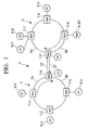
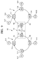
- a communication system 1 used in a first embodiment according to the present invention comprises a first LAN 3 and a second LAN 5 which are connected via route hubs RH4 and RH6 so that data can be exchanged between two LANs.
- the first LAN 3 has route hubs 7-1 (RH1) to 7-4 (RH4) connected via a loop-type data transmission line 4
- the second LAN 5 has route hubs 7-6 (RH6) to 7-9 (RH9) connected via a loop-type data transmission line 6.
- Route hubs RH4 and RH6 are connected by data transmission lines 23 and 27.
- the network topology of the first LAN 3 and the second LAN 5 need not always be a loop; it may be, for example, one of other topologies such as a bus or a star.
- One or more node terminals are connected to each of the plurality of route hubs.
- terminals are represented as N1, ..., N4, N6, ..., N10.
- the communication system is configured so that communication data may be exchanged between route hubs RH, between node terminals N, and between a node terminal N and a route hub RH, for example, in the arrow direction, shown in FIG. 1, via the loop-type data transmission line, regardless of whether or not the destination and the source are in the same LAN.
- addresses are assigned by assuming a one-loop transmission route, as shown in FIG. 2, for the whole communication system including the first LAN 3, second LAN 5, data transmission line 23, and data transmission line 27.
- any of the following functional units may be used, as necessary,, as the node terminal N. They include a cellular phone, a facsimile (FAX), a digital TV, radio receiver, a navigation system (NV), a DVD(Digital Video Disc or Digital Versatile Disc) -ROM unit, a CD(Compact Disc) -ROM unit, a DAT (Digital Audio Tape recorder), an MD (Mini Disc), a digital signal processor (DSP) built-in audio amplifier, a CAN (Controller Area Network) interface, sensors such as a directional sensor or a speed sensor, a monitor, and a personal computer installed in a car.
- FAX facsimile
- NV navigation system
- DVD(Digital Video Disc or Digital Versatile Disc) -ROM unit a CD(Compact Disc) -ROM unit
- a DAT Digital Audio Tape recorder
- MD Mini Disc
- DSP digital signal processor built-in audio amplifier
- CAN Controller Area Network
- Route hub RH4 and route hub RH6 each have the gateway function.
- Route hub RH4 sends an address assignment frame, which contains an address value, to the first LAN 3 in the clockwise direction and, using the address value, assigns addresses to the route hubs and the node terminals sequentially from route hub RH1, which is nearest to route hub RH4, to route hub RH4 itself.
- route hub RH4 Upon receiving the address assignment frame that has been returned, route hub RH4 sends it to route hub RH6.
- route hub RH6 When route hub RH6 receives the address assignment frame, it assigns to itself the address value indicated by the received frame. Then, route hub RH6 sends the address assignment frame to the second LAN 5 in the clockwise direction and, using the address value, assigns addresses to the route hubs and the node terminals sequentially from route hub RH7 which is nearest to route hub RH6. Upon receiving the address assignment frame that has been returned, route hub RH6 sends it back to route hub RH4.
- the addresses thus assigned to the route hubs (RH) and node terminals (N) are used, as will be described later, when destination addresses or source addresses are described . At the same time, they are used to determine which LAN a route hub (RH) or a node terminal N (N) belongs to.
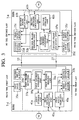
- route hub RH4 comprises a first frame sending unit 31a that sends the address assignment frame containing an address value, a first output buffer 33a in which data or the address assignment frame to be output to the first LAN 3 is temporarily stored, a second output buffer 33b in which data or the address assignment frame to be output to the data transmission line 23 is temporarily stored, a first input buffer 35a in which data or the address assignment frame received from the first LAN 3 is temporarily stored, a second input buffer 35b in which data or the address assignment frame received from the data transmission line 27 is temporarily stored, a first frame receiving unit 37a that receives the address assignment frame, and a first address assignment unit 39a that stores the address value included in the received address assignment frame into a first storage unit 41a.
- Route hub RH4 further comprises the first storage unit 41a in which its own address and the node addresses of a plurality of node terminals connected to its own route hub, both of which are assigned by the first address assignment unit 39a, are stored, a first network identifying unit 43a that checks if the destination belongs to its own LAN based on the destination address added to the communication data received from a node terminal N or a route hub RH belonging to the first LAN 3 and on its own address stored in the first storage unit 41a, and a first route selection unit 45a that selects an appropriate route as the destination of communication data according to the result of the network identification so that the communication data may be sent via the selected route.
- route hub RH6 comprises a second frame sending unit 31b that sends the address assignment frame, a third output buffer 33c in which data or the address assignment frame to be output to the second LAN 5 is temporarily stored, a fourth output buffer 33d in which data or the address assignment frame to be output to the data transmission line 27 is temporarily stored, a third input buffer 35c in which data or the address assignment frame received from the second LAN 5 is temporarily stored, a fourth input buffer 35d in which data or the address assignment frame received from the data transmission line 23 is temporarily stored, a second frame receiving unit 37b that receives the address assignment frame, and a second address assignment unit 39b that stores the address value included in the received address assignment frame into a second storage unit 41b.
- Route hub RH6 further comprises the second storage unit 41b in which its own address and the node addresses of a plurality of node terminals N connected to its own route hub, both of which are assigned by the second address assignment unit 39b, are stored, a second network identifying unit 43b that checks if the destination belongs to its own LAN based on the destination address added to the communication data received from a node terminal N or a route hub RH belonging to the second LAN 5 and on its own address stored in the second storage unit 41b, and a second route selection unit 45b that selects an appropriate route as the destination of communication data according to the result of the network identification so that the communication data is sent via the selected route.
- the second storage unit 41b in which its own address and the node addresses of a plurality of node terminals N connected to its own route hub, both of which are assigned by the second address assignment unit 39b, are stored
- a second network identifying unit 43b that checks if the destination belongs to its own LAN based on the destination address added to the communication data received
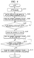
- FIG.4 is a flowchart showing the address assignment processing for route hub RH4
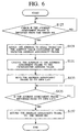
- FIG.5 is a flowchart showing the address assignment processing for route hubs other than route hubs RH4 and RH6,
- FIG.6 is a flowchart showing the address assignment processing of route hub RH6.
- route hub RH4 assigns "0" to all addresses (step S101) and sets its own RH as the origin RH of the address assignment frame (step S103). Then, the first frame sending unit 31a sends the address assignment frame, which contains an address value (for example, "0"), to the first LAN 3 in the clockwise direction via the first output buffer 33a (step S105).
- each of route hubs RH1, RH2, and RH3 checks if it receives the address assignment frame from the upstream RH (step S117) and, if it receives the address assignment frame, extracts the address value from the address assignment frame (step S119).
- the route hub increments the address value by one successively and assigns the successively incremented address value to its own route hub and to the node terminals connected to the route hub (step S121). After that, the route hub changes the address value contained in the address assignment frame to the last incremented value (step S123) and sends the address assignment frame to the downstream RH (step S125).
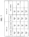
- the RH address '01' is assigned to route hub RH1 belonging to the first LAN 3, and the node address '02' is assigned to node terminal N1 connected to route hub RH1. Then, the RH address '03' is assigned to route hub RH2, and the node address '04' is assigned to node terminal N2 connected to route hub RH2. In addition, the RH address '05 ' is assigned to route hub RH3, and the node address '06' is assigned to the node terminal N3 connected to route hub RH3.
- the first frame receiving unit 37a in the route hub RH4 checks if the address assignment frame is returned from the first LAN 3 via the first input buffer 35a. If the address assignment frame is returned, route hub RH4 assigns the address to itself based on the address value contained in the received address assignment frame (step S109). In this case, as shown in FIG.7, the RH address '07' is assigned to route hub RH4, and the node address '08' is assigned to node terminal N4 connected to route hub RH4.
- the RH address '07' assigned to route hub RH4 is also stored in the first storage unit 41a.
- the first frame sending unit 31a sends the address assignment frame containing the address value '08' to the route hub RH6 via the second output buffer 33b and the data transmission line 23 (step S111).
- the second frame receiving unit 37b in the route hub RH6 checks if the address assignment frame is received from the origin RH (root hub RH4) via the fourth input buffer 35d (step S127). If the address assignment frame is received, route hub RH6 assigns the address to itself based on the address value '08' contained in the received address assignment frame (step S129).
- the RH address '10' is assigned to route hub RH6, and the node address '11' is assigned to node terminal N6 connected to route hub RH6.
- the RH address '10' assigned to route hub RH6 is stored in the second storage unit 41b.
- step S131 the address value contained in the address assignment frame is changed to the incremented address value '11' (step S131), and the second frame sending unit 31b sends the address assignment frame containing the address value '11' to the second LAN 5 in the clockwise direction via the third output buffer 33c (step S133).
- the RH address '12' is assigned to route hub RH7 of the second LAN 5
- the node address '13' is assigned to node terminal N7 connected to route hub RH7
- the node address '14' is assigned to node terminal N8, as shown in FIG. 7.
- the RH address '15' is assigned to route hub RH8, and the node address '16' is assigned to node terminal N9 connected to route hub RH8.
- the RH address '17' is assigned to route hub RH9
- the node address '18' is assigned to node terminal N10 connected to route hub RH9.
- the second frame receiving unit 37b checks if the address assignment frame is received from the upstream of the second LAN 5 via the third input buffer 35c (step S135). If the address assignment frame is received, the second frame sending unit 31b returns the address assignment frame to route hub RH4, which is the origin RH, via the fourth output buffer 33d and the data transmission line 27 (step S137).
- the first frame receiving unit 37a of route hub RH4 checks if the address assignment frame is received from the route hub RH6 via the second input buffer 35b (step S113). If the address assignment frame is received, route hub RH4 erases the address assignment frame and finishes the address assignment processing (step S115).
- route hub RH4 sends the address assignment frame, which contains the address value, to the first LAN 3 in the clockwise direction and, using the address value, assigns addresses to the route hubs and the node terminals sequentially from route hub RH1, which is nearest to route hub RH4, to route hub RH4 itself.
- route hub RH4 sends it to route hub RH6.
- route hub RH6 assigns the address value contained in the received address assignment frame to itself, sends the address assignment frame to the second LAN 5 in the clockwise direction, and, using the address value, assigns addresses to the route hubs and the node terminals sequentially from route hub RH7 that is nearest to route hub RH6.
- route hub RH6 returns it to route hub RH4.
- addresses are assigned to the route hubs RH and node terminals N in the first LAN 3 and second LAN 5 automatically and easily by assuming a one-loop transmission route, as shown in FIG.2, for the whole communication system including the first LAN 3, second LAN 5, data transmission line 23, and data transmission line 27.
- route hub RH4 constantly checks if communication data is sent from a node terminal N or a route hub RH in the first LAN 3 (step S201). If communication data is received, route hub RH4 decodes the source/destination address contained in the communication data.
- Route hub RH4 extracts the destination address from the decoded source/destination address (step S203), and the first network identifying unit 43a reads its own address stored the first storage unit 41a (step S205). Then, the first network identifying unit 43a compares the destination address with its own address stored in the first storage unit 41a to check if the destination is included in this LAN (step S207). Based on the result of the checking, the first route selection unit 45a selects an appropriate route as the destination of communication data.
- the address of route hub R114 is the largest address in the first LAN 3, as shown in FIG.7. Therefore, if the destination address of the communication data is equal to or smaller than the address of route hub RH4, it is found that the destination is in the first LAN 3. In this case, the first route selection unit 45a selects the first output buffer 33a to select the route to this LAN as the destination of the communication data (step S209). Therefore, the communication data is sent to the first LAN 3 via the first output buffer 33a.
- the first route selection unit 45a selects the second output buffer 33b to select the route to the other LAN as the destination of the communication data (step S211). Therefore, the communication data is sent to the second LAN 5 via the second output buffer 33b and the data transmission line 23.
- route hub RH6 The operation of route hub RH6 is the same as that of route hub RH4.
- the address of route hub RH6 is the smallest address in the second LAN 5, as shown in FIG.7. Therefore, if the destination address of the communication data is equal to or larger than the address of route hub RH6, it is found that the destination is in the second LAN 5.
- the second route selection unit 45b selects the third output buffer 33c to select the route to this LAN as the destination of the communication data. Therefore, the communication data is sent to the second LAN 5 via the third output buffer 33c.
- the second route selection unit 45b selects the fourth output buffer 33d to select the route to the other LAN as the destination of the communication data. Therefore, the communication data is sent to the first LAN 3 via the fourth output buffer 33d and the data transmission line 27.
- route hub RH4 or RH6 receives communication data, a check is made to see if the destination address is equal to, larger than, or smaller than the assigned address of route hub RH4 or route hub RH6.
- This makes it possible to determine which LAN, first LAN 3 or second LAN 5, the destination of the communication data belongs to. Therefore, this system sends communication to the specified destination reliably. As a result, this system allows communication data to be sent reliably to the destination while significantly increasing the per-unit-time data transmission amount.
- a communication system 61 used in a second embodiment according to the present invention will be described with emphasis on the difference between the communication system 1 in the first embodiment and the communication system 61.
- the numbers of components in the communication system 61 in the second embodiment corresponding to those in the first embodiment are the same and the description of such components are not repeated.
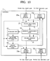
- the communication system 61 is characterized in that the first LAN 3 and the second LAN 5 are directly connected by a gateway 11 which has the gateway function of route hub RH4 and route hub RH6 described in the first embodiment.
- the gateway 11 comprises a frame sending unit 31, the first output buffer 33a, the first input buffer 35a, a frame receiving unit 37, an address assignment unit 39, the third output buffer 33c, and the third input buffer 35c.
- the frame sending unit 31 has the function of the first frame sending unit 31a and the second frame sending unit 31b shown in FIG.3.
- the frame receiving unit 37 has the function of the first frame receiving unit 37a and the second frame receiving unit 37b shown in FIG.3.
- the gateway 11 further comprises a storage unit 41 in which its own address and the addresses of a plurality of node terminals N connected to this gateway, both of which are assigned by the address assignment unit 39, are stored, a network identifying unit 43 that checks which LAN, first LAN 3 or second LAN 5, the destination belongs to based on the destination address contained in the communication data received from a node terminal N or a route hub RH in the first LAN 3 or second LAN 5, and a route selection unit 45 that selects an appropriate route as the destination of the communication data based on the network identification result to send the communication data via the selected route.
- a storage unit 41 in which its own address and the addresses of a plurality of node terminals N connected to this gateway, both of which are assigned by the address assignment unit 39, are stored
- a network identifying unit 43 that checks which LAN, first LAN 3 or second LAN 5, the destination belongs to based on the destination address contained in the communication data received from a node terminal N or a route hub RH in the first LAN 3
- the gateway 11 has two functions: one is the function which receives communication data from a node terminal N or a route hub RH in the first LAN 3 and switches the destination of the received communication data to this first LAN 3 or the second LAN 5, and the other is the function which receives communication data from a node terminal N or a route hub RH in the second LAN 5 and switches the destination of the received communication data to this second LAN 5 or the first LAN 3.
- the gateway 11 sends the address assignment frame, which contains an address value, to the first LAN 3 in the clockwise direction and, using the address value, assigns addresses to the route hubs, node terminals, and gateway 11 itself sequentially from route hub RH1, which is nearest to gateway 11, to gateway 11 itself. Then, the gateway 11 sends the address assignment frame to the second LAN 5 in the clockwise direction and, using the address value, assigns addresses to the route hubs and node terminals sequentially from route hub RH7 that is nearest to gateway 11.
- addresses may be assigned automatically to the route hubs RH and node terminals in the same way addresses are assigned in the communication system in the first embodiment.
- the configuration becomes simpler and, at the same time, addresses may be assigned more quickly.
- the gateway 11 when the gateway 11 receives communication data containing an address, the gateway 11 checks if the destination address of the communication data is equal to, larger than, or smaller than its own address to find which LAN, first LAN 3 or second LAN 5, the communication data is addressed to. Therefore, the communication data may be sent reliably to the specified destination and, as a result, data may be exchanged easily between the first LAN 3 and the second LAN 5 as in the first embodiment.
- addresses are assigned sequentially to the route hubs RH and node terminals N belonging to the loop-type first LAN 3 and second LAN 5 in the clockwise direction, addresses may be assigned sequentially to the route hubs and node terminals in the counterclockwise direction.
- addresses are assigned sequentially to the route hubs and node terminals in the clockwise direction while incrementing the address by 1 beginning at 1 (1, 2, 3, ...), addresses may be assigned to the route hubs and node terminals while decrementing the address by 1 beginning at 18 (18, 17, 16, ).
- addresses are assigned sequentially to the route hubs and node terminals while incrementing the address by 1 beginning at 1 (1, 2, 3, ...)
- a plurality of addresses each of which corresponds to a route hub RH or a node terminal N, may be stored in advance in the address assignment frame.
- each route hub RH and each node terminal N may extract the corresponding address value for its own sequential address.
- node terminal dependent addresses such as those, for example, which are at maximum twice as large as an address assigned, in advance, to each type of node terminals connected to the route hubs may be assigned as addresses.
- a communication medium such as a communication line is used for the data transmission lines 23 and 27 when the first LAN 3 and the second LAN 5 are remotely located as in the first embodiment, it is to be readily understood that not only the communication line but also an infrared ray or an electromagnetic wave may be used as the communication medium. It should also be understood that various changes and modifications may be made in the present invention within the spirit and scope as set out in the accompanying claims.
Abstract
Description
- The present invention relates to a communication method for exchanging data between node terminals, between routers, and between a node terminal and a router, for use in a communication system composed of a pair of networks which are connected by data transmission lines via a gateway and each of which has a plurality of routers each having one or more node terminals. In particular, the present invention relates to a communication method, a communication system, and a gateway used in the communication system that automatically assign addresses to routers and node terminals to reliably send communication data to destinations while significantly increasing the per-unit-time transmission amount.
- Conventionally, a communication system, such as the one disclosed in Japanese Patent Laid-Open Publication No. Sho 59-62245, is known in which LANs (Local Area Network), each of which allows a plurality of stations to exchange data, are connected via a gateway for data exchange between a pair of LANs.
- In the technology disclosed in the above publication, a sender/receiver address specifying the data sender and receiver, as well as the station address indicating the station to or from which data is sent or received and the network address indicating the network to which the station belongs, is added to communication data. During data communication, this address is referenced to reliably send data between LANs even when data is transferred across networks.
- However, because there are many types of addresses that are added to communication data used in the conventional communication system described above, a relatively large data desciprtion area must be reserved for the address description area within the data communication data. The need to reserve a large data description area prevents per-unit-time data transmission amount from increasing, offering a problem that must be solved.
- The communication method, the communication system, and the gateway used in the communication system disclosed in Japanese Patent Laid-Open Publication No. Hei 10-294751 are known as a solution to this problem. The method disclosed in this publication is used in a communication system composed of a pair of networks which are connected by data transmission lines via a gateway and each of which has a plurality of routers each having one or more node terminals. When data is exchanged between node terminals, between routers, and between a node terminal and a router, the router writes the source/destination addresses in the address description area in the communication data in advance and then sends the communication data, in which the source/destination addresses are described, to the destination.
- On the other hand, the gateway decodes the source/destination addresses included in the received communication data, checks if the destination and the source are in the same network based on the decoded source/destination addresses and the previously-stored network identification data, selects an appropriate route for the destination of the communication data based on the network identification checking, and then sends the communication data to the destination via the selected route.
- Therefore, by simply storing the source/destination addresses in a small address description area provided in the communication data, this method significantly increases the per-unit-time data transmission amount and, at the same time, reliably sends communication data.
- However, although the communication method, the communication system, and the gateway used in the communication system disclosed in Japanese Patent Laid-Open Publication No. Hei 10-294751 are used to exchange data between a pair of networks configured in the shape of the numeral 8, no method is disclosed for automatically assigning addresses to the routers and node terminals belonging to each network of the pair.
- It is an object of the present invention to provide a communication method, a communication system, and a gateway used in the communication system that can automatically assign addresses to routers and node terminals, check, with the use of the assigned addresses, which network the communication data is to be addressed to, and reliably send the communication data to the destination while significantly increasing the per-unit-time data transmission amount.
- To achieve the above object, there is provided a communication method for exchanging data between node terminals, between routers, or between a node terminal and a router using a communication system composed of a pair of networks each comprising a plurality of routers each having one or more the node terminals, the plurality of routers being connected via a first data transmission line, the pair of networks being connected via a pair of routers belonging to the pair of networks respectively and a second data transmission line connecting the pair of routers, the communication method comprising the steps of: causing one of the pair of routers to send into one direction an address assignment frame containing an address value to one of the pair of networks, to assign an address to each router and each node terminal, based on the address value, sequentially from the router, which is nearest to the one of pairs of routers, to the one of pairs of routers itself, and to send the address assignment frame, which has been returned, to the other router of the pair of routers; and causing the other router of the pair of routers to assign the address to itself based on the address value contained in the received address assignment frame, to send the address assignment frame to the other network into the one direction, to assign the address to each router and each node terminal, based on the address value, sequentially from the router which is nearest to the other router, and to return the address assignment frame, which has been returned, to the one of the pair of routers.
- According to this invention, one of the pair of routers sends into one direction an address assignment frame containing an address value to one of the pair of networks, assigns an address to each router and each node terminal, based on the address value, sequentially from the router, which is nearest to the one of pairs of routers, to the one of pairs of routers itself, and sends the address assignment frame, which has been returned, to the other router of the pair of routers. The other router of the pair of routers assigns the address to itself based on the address value contained in the received address assignment frame, sends the address assignment frame to the other network into the one direction, assigns the address to each router and each node terminal, based on the address value, sequentially from the router which is nearest to the other router, and returns the address assignment frame, which has been returned, to the one of the pair of routers. Therefore, addresses may be assigned automatically to the routers and the node terminals belonging to the pair of networks.
- In a preferred embodiment of the present invention, each of the routers adds at least a destination address to communication data to be sent and sends the communication data containing the destination address to a destination, and each of the pair of routers checks, based on the destination address contained in received communication data and the address assigned to itself, if the destination is included in the network to which the router itself belongs, selects, based on a result of the checking, a route via which the communication data is to be sent, and sends the communication data to the destination via the selected route.
- In this mode, each of the routers adds at least a destination address to communication data to be sent and sends the communication data containing the destination address to a destination, and each of the pair of routers checks, based on the destination address contained in received communication data and the address assigned to itself, if the destination is included in the network to which the router itself belongs, selects, based on a result of the checking, a route via which the communication data is to be sent, and sends the communication data to the destination via the selected route. Therefore, communication data may be sent reliably to the destination while significantly increasing the per-unit-time data transmission amount.
- In a preferred embodiment of the present invention, when assigning the address to each of the routers and the node terminals, each of the pair of routers increments or decrements the address.
- In this mode, because each of the pair of routers increments or decrements the address when assigning the address to each router and each node terminal, it is easily determined which network the destination belongs to by comparing the destination address with the address of the router itself.
- To achieve the above object, there is provided a communication system which is composed of a pair of networks each comprising a plurality of routers each having one or more node terminals and in which data is exchanged between the node terminals, between the routers, or between a node terminal and a router, the plurality of routers being connected via a first data transmission line, the pair of networks being connected via a pair of routers belonging to the pair of networks respectively and a second data transmission line connecting the pair of routers, wherein one of the pair of routers has first address assignment means for sending into one direction an address assignment frame containing an address value to one of the pair of networks, for assigning an address to each router and each node terminal, based on the address value, sequentially from the router, which is nearest to the one of pairs of routers, to the one of pairs of routers itself, and for sending the address assignment frame, which has been returned, to the other router of the pair of routers; and wherein the other router of the pair of routers has second address assignment means for assigning the address to itself based on the address value contained in the received address assignment frame, for sending the address assignment frame to the other network into the one direction, for assigning the address to each router and each node terminal, based on the address value, sequentially from the router which is nearest to the other router, and for returning the address assignment frame, which has been returned, to the one Of the pair of routers.
- According to this invention, the first address assignment means provided by one of the pair of routers sends into one direction an address assignment frame containing an address value to one of the pair of networks, assigns an address to each router and each node terminal, based on the address value, sequentially from the router, which is nearest to the one of pairs of routers, to the one of pairs of routers itself, and sends the address assignment frame, which has been returned, to the other router of the pair of routers. The second address assignment means provided by the other router of the pair of routers assigns the address to itself based on the address value contained in the received address assignment frame, sends the address assignment frame to the other network into the one direction, assigns the address to each router and each node terminal, based on the address value, sequentially from the router which is nearest to the other router, and returns the address assignment frame, which has been returned, to the one of the pair of routers. Therefore, addresses may be assigned automatically to the routers and the node terminals belonging to the pair of networks.
- In a preferred embodiment of the present invention, each of the routers has sending means for adding at least a destination address to communication data to be sent and for sending the communication data containing the destination address to a destination, and each of the pair of routers comprises: checking means for checking, based on the destination address contained in received communication data and its own address stored in the storing means, if the destination is included in the network to which the router itself belongs; and route selection means for selecting, based on a result of the checking, a route via which the communication data is to be sent and for sending the communication data to the destination via the selected route.
- In this mode, the sending means provided by each of the routers adds at least a destination address to communication data to be sent and sends the communication data containing the destination address to a destination. In each of the pair of routers, the checking means checks, based on the destination address contained in received communication data and its own address stored in the storing means, if the destination is included in the network to which the router itself belongs, and the route selection means selects, based on a result of the checking, a route via which the communication data is to be sent and sends the communication data to the destination via the selected route. Therefore, communication data may be sent reliably to the destination while significantly increasing the per-unit-time data transmission amount.
- In a preferred embodiment of the present invention, when assigning the address to each of the routers and the node terminals, each of the pair of routers increments or decrements the address.
- In this mode, because each of the pair of routers increments or decrements the address when assigning the address to each router and each node terminal, it is easily determined which network the destination belongs to by comparing the destination address with the address of the router itself.
- To achieve the above object, there is provided a communication method for exchanging data between node terminals, between routers, or between a node terminal and a router using a communication system composed of a pair of networks each comprising a plurality of routers each having one or more the node terminals, the plurality of routers being connected via a data transmission line, the pair of networks being connected via a gateway, the communication method comprising the steps, by the gateway, of sending into one direction an address assignment frame containing an address value to one of the pair of networks; assigning an address to each router, each node terminal, and the gateway itself, based on the address value, sequentially from the router, which is nearest to the gateway, to the gateway itself; sending the address assignment frame to the other route network into the one direction; and assigning the address to each router and each node terminal, based on the address value, sequentially from the router which is nearest to the gateway.
- According to this invention, the gateway sends into one direction an address assignment frame containing an address value to one of the pair of networks, assigns an address to each router, each node terminal, and the gateway itself, based on the address value, sequentially from the router, which is nearest to the gateway, to the gateway itself, sends the address assignment frame to the other route network into the one direction, and assigns the address to each router and each node terminal, based on the address value, sequentially from the router which is nearest to the gateway. Therefore, addresses may be assigned to the routers and the node terminals, belonging to the pair of networks, automatically and more speedily.
- In a preferred embodiment of the present invention, each of the routers adds at least a destination address to communication data to be sent and sends the communication data containing the destination address to a destination, and the gateway checks, based on the destination address contained in received communication data and the address assigned to the gateway itself, which network the destination belongs to, selects, based on a result of the checking, a route via which the communication data is to be sent, and sends the communication data to the destination via the selected route.
- In this mode, each of the routers adds at least a destination address to communication data to be sent and sends the communication data containing the destination address to a destination. The gateway checks, based on the destination address contained in received communication data and the address assigned to the gateway itself, which network the destination belongs to, selects, based on a result of the checking, a route via which the communication data is to be sent, and sends the communication data to the destination via the selected route. Therefore, communication data may be sent reliably to the destination while significantly increasing the per-unit-time data transmission amount.
- In a preferred embodiment of the present invention, when assigning the address to each of the routers, each of the node terminals, and the gateway, the gateway increments or decrements the address.
- In this mode, because the gateway increments or decrements the address when assigning the address to each router, each node terminal, and to the gateway, it is easily determined which network the destination belongs to by comparing the destination address with the address of the gateway itself.
- To achieve the above object, there is provided a communication system which is composed of a pair of networks each comprising a plurality of routers each having one or more node terminals and in which data is exchanged between the node terminals, between the routers, or between a node terminal and a router, the plurality of routers being connected via a data transmission line, the pair of networks being connected via a gateway, wherein the gateway has address assignment means for sending into one direction an address assignment frame containing an address value to one of the pair of networks,for assigning an address to each router, each node terminal, and the gateway itself, based on the address value, sequentially from the router, which is nearest to the gateway, to the gateway itself, for sending the address assignment frame to the other network into the one direction, and for assigning the address to each router and each node terminal, based on the address value, sequentially from the router which is nearest to the gateway.
- According to this invention, the address assignment means provided by the gateway sends into one direction an address assignment frame containing an address value to one of the pair of networks, assigns an address to each router, each node terminal, and the gateway itself, based on the address value, sequentially from the router, which is nearest to the gateway, to the gateway itself, sends the address assignment frame to the other network into the one direction, and assigns the address to each router and each node terminal, based on the address value, sequentially from the router which is nearest to the gateway. Therefore, addresses may be assigned to the routers and the node terminals, belonging to the pair of networks, automatically and more speedily.
- To achieve the above object, there is provided a gateway for use in a communication system in which a pair of networks, each comprising a plurality of routers each having one or more the node terminals, are connected so that data may be exchanged between the node terminals, between the routers, or between a node terminal and a router, the plurality of routers being connected via a data transmission line, the gateway comprising: address assignment means for sending into one direction an address assignment frame containing an address value to one of the pair of networks, for assigning an address to each router, each node terminal, and the gateway itself, based on the address value, sequentially from the router, which is nearest to the gateway, to the gateway itself, for sending the address assignment frame to the other network into the one direction, and for assigning the address to each router and each node terminal, based on the address value, sequentially from the router which is nearest to the gateway; storing means for storing its own address assigned by the address assignment means; checking means for checking, based on the destination address contained in received communication data and its the own address stored in the storing means, which network the destination belongs to; and route selection means for selecting, based on a result of the checking, a route via which the communication data is to be sent, and for sending the communication data to the destination via the selected route.
- According to this invention, the address assignment means sends into one direction an address assignment frame containing an address value to one of the pair of networks, and assigns an address to each router, each node terminal, and the gateway itself, based on the address value, sequentially from the router, which is nearest to the gateway, to the gateway itself. Then the address assignment means sends the address assignment frame to the other network into the one direction, and assigns the address to each router and each node terminal, based on the address value, sequentially from the router which is nearest to the gateway. The checking means checks, based on the destination address contained in received communication data and its the own address stored in the storing means, which network the destination belongs to. The route selection means selects, based on a result of the checking, a route via which the communication data is to be sent, and sends the communication data to the destination via the selected route. Therefore, addresses may be assigned to the routers and the node terminals, belonging to the pair of networks, automatically and more speedily. In addition, communication data may be sent reliably to the destination while significantly increasing the per-unit-time data transmission amount.
- The nature, principle and utility of the invention will become more apparent from the following detailed description when read in conjunction with the accompanying drawings.
- In the accompanying drawings:
- FIG.1 is an overall block diagram showing the configuration of a communication system used in a first embodiment of the present invention;
- FIG.2 is a schematic diagram showing the communication route of the communication system according to the present invention;
- FIG.3 is a block diagram showing the main part of the communication system used in the first embodiment of the present invention;
- FIG.4 is a flowchart showing the address assignment procedure for one of the route hubs performing the gateway function;
- FIG.5 is a flowchart showing the address assignment procedure for route hubs other than those having the gateway function;
- FIG.6 is a flowchart showing the address assignment procedure for another of the route hubs performing the gateway function;
- FIG.7 is a diagram showing an example of addresses assigned to route hubs and node terminals.
- FIG.8 is a flowchart showing the communication operation of the communication system according to the present invention;
- FIG.9 is an overall block diagram showing the configuration of the communication used in a second embodiment of the present invention; and
- FIG.10 is a block diagram showing the main part of the communication system used in the second embodiment of the present invention.
-
- A communication method, a communication system, and a gateway used in the communication system according to the present invention will be described below in detail with reference to the accompanying drawings.
- Referring to FIG.1, a communication system 1 used in a first embodiment according to the present invention comprises a
first LAN 3 and asecond LAN 5 which are connected via route hubs RH4 and RH6 so that data can be exchanged between two LANs. Thefirst LAN 3 has route hubs 7-1 (RH1) to 7-4 (RH4) connected via a loop-type data transmission line 4, and thesecond LAN 5 has route hubs 7-6 (RH6) to 7-9 (RH9) connected via a loop-type data transmission line 6. Route hubs RH4 and RH6 are connected bydata transmission lines first LAN 3 and thesecond LAN 5 need not always be a loop; it may be, for example, one of other topologies such as a bus or a star. - One or more node terminals are connected to each of the plurality of route hubs. In the figure, terminals are represented as N1, ..., N4, N6, ..., N10. The communication system is configured so that communication data may be exchanged between route hubs RH, between node terminals N, and between a node terminal N and a route hub RH, for example, in the arrow direction, shown in FIG. 1, via the loop-type data transmission line, regardless of whether or not the destination and the source are in the same LAN. Also, addresses are assigned by assuming a one-loop transmission route, as shown in FIG. 2, for the whole communication system including the
first LAN 3,second LAN 5,data transmission line 23, anddata transmission line 27. - When the communication system according to the present invention is applied, for example, to an automobile communication system in which digital audio data is exchanged, any of the following functional units may be used, as necessary,, as the node terminal N. They include a cellular phone, a facsimile (FAX), a digital TV, radio receiver, a navigation system (NV), a DVD(Digital Video Disc or Digital Versatile Disc) -ROM unit, a CD(Compact Disc) -ROM unit, a DAT (Digital Audio Tape recorder), an MD (Mini Disc), a digital signal processor (DSP) built-in audio amplifier, a CAN (Controller Area Network) interface, sensors such as a directional sensor or a speed sensor, a monitor, and a personal computer installed in a car.
- Route hub RH4 and route hub RH6 each have the gateway function. Route hub RH4 sends an address assignment frame, which contains an address value, to the
first LAN 3 in the clockwise direction and, using the address value, assigns addresses to the route hubs and the node terminals sequentially from route hub RH1, which is nearest to route hub RH4, to route hub RH4 itself. Upon receiving the address assignment frame that has been returned, route hub RH4 sends it to route hub RH6. - When route hub RH6 receives the address assignment frame, it assigns to itself the address value indicated by the received frame. Then, route hub RH6 sends the address assignment frame to the
second LAN 5 in the clockwise direction and, using the address value, assigns addresses to the route hubs and the node terminals sequentially from route hub RH7 which is nearest to route hub RH6. Upon receiving the address assignment frame that has been returned, route hub RH6 sends it back to route hub RH4. - In this way, a unique address is assigned to each of route hubs RH1, ..., RH4, RH6, ...RH9 and each of node terminals N1, ...,N4, N6, ..., N10. The addresses thus assigned to the route hubs (RH) and node terminals (N) are used, as will be described later, when destination addresses or source addresses are described . At the same time, they are used to determine which LAN a route hub (RH) or a node terminal N (N) belongs to.
- As shown in FIG. 3, route hub RH4 comprises a first
frame sending unit 31a that sends the address assignment frame containing an address value, afirst output buffer 33a in which data or the address assignment frame to be output to thefirst LAN 3 is temporarily stored, asecond output buffer 33b in which data or the address assignment frame to be output to thedata transmission line 23 is temporarily stored, afirst input buffer 35a in which data or the address assignment frame received from thefirst LAN 3 is temporarily stored, asecond input buffer 35b in which data or the address assignment frame received from thedata transmission line 27 is temporarily stored, a firstframe receiving unit 37a that receives the address assignment frame, and a firstaddress assignment unit 39a that stores the address value included in the received address assignment frame into afirst storage unit 41a. - Route hub RH4 further comprises the
first storage unit 41a in which its own address and the node addresses of a plurality of node terminals connected to its own route hub, both of which are assigned by the firstaddress assignment unit 39a, are stored, a firstnetwork identifying unit 43a that checks if the destination belongs to its own LAN based on the destination address added to the communication data received from a node terminal N or a route hub RH belonging to thefirst LAN 3 and on its own address stored in thefirst storage unit 41a, and a firstroute selection unit 45a that selects an appropriate route as the destination of communication data according to the result of the network identification so that the communication data may be sent via the selected route. - As shown in FIG.3, route hub RH6 comprises a second
frame sending unit 31b that sends the address assignment frame, athird output buffer 33c in which data or the address assignment frame to be output to thesecond LAN 5 is temporarily stored, afourth output buffer 33d in which data or the address assignment frame to be output to thedata transmission line 27 is temporarily stored, athird input buffer 35c in which data or the address assignment frame received from thesecond LAN 5 is temporarily stored, afourth input buffer 35d in which data or the address assignment frame received from thedata transmission line 23 is temporarily stored, a secondframe receiving unit 37b that receives the address assignment frame, and a secondaddress assignment unit 39b that stores the address value included in the received address assignment frame into asecond storage unit 41b. - Route hub RH6 further comprises the
second storage unit 41b in which its own address and the node addresses of a plurality of node terminals N connected to its own route hub, both of which are assigned by the secondaddress assignment unit 39b, are stored, a secondnetwork identifying unit 43b that checks if the destination belongs to its own LAN based on the destination address added to the communication data received from a node terminal N or a route hub RH belonging to thesecond LAN 5 and on its own address stored in thesecond storage unit 41b, and a secondroute selection unit 45b that selects an appropriate route as the destination of communication data according to the result of the network identification so that the communication data is sent via the selected route. - Next, referring to FIGS.4 to 6, the address assignment procedure for the communication system, configured in accordance with the present invention, will be described. FIG.4 is a flowchart showing the address assignment processing for route hub RH4, FIG.5 is a flowchart showing the address assignment processing for route hubs other than route hubs RH4 and RH6, and FIG.6 is a flowchart showing the address assignment processing of route hub RH6.
- First, in the flowchart shown in FIG.4, route hub RH4 assigns "0" to all addresses (step S101) and sets its own RH as the origin RH of the address assignment frame (step S103). Then, the first
frame sending unit 31a sends the address assignment frame, which contains an address value (for example, "0"), to thefirst LAN 3 in the clockwise direction via thefirst output buffer 33a (step S105). - Next, in the flowchart in FIG. 5, each of route hubs RH1, RH2, and RH3 checks if it receives the address assignment frame from the upstream RH (step S117) and, if it receives the address assignment frame, extracts the address value from the address assignment frame (step S119).
- The route hub increments the address value by one successively and assigns the successively incremented address value to its own route hub and to the node terminals connected to the route hub (step S121). After that, the route hub changes the address value contained in the address assignment frame to the last incremented value (step S123) and sends the address assignment frame to the downstream RH (step S125).
- As shown in FIG.7, as a result of the above steps, the RH address '01' is assigned to route hub RH1 belonging to the
first LAN 3, and the node address '02' is assigned to node terminal N1 connected to route hub RH1. Then, the RH address '03' is assigned to route hub RH2, and the node address '04' is assigned to node terminal N2 connected to route hub RH2. In addition, the RH address '05' is assigned to route hub RH3, and the node address '06' is assigned to the node terminal N3 connected to route hub RH3. - Next, in FIG.4, the first
frame receiving unit 37a in the route hub RH4 checks if the address assignment frame is returned from thefirst LAN 3 via thefirst input buffer 35a. If the address assignment frame is returned, route hub RH4 assigns the address to itself based on the address value contained in the received address assignment frame (step S109). In this case, as shown in FIG.7, the RH address '07' is assigned to route hub RH4, and the node address '08' is assigned to node terminal N4 connected to route hub RH4. - The RH address '07' assigned to route hub RH4 is also stored in the
first storage unit 41a. In addition, the firstframe sending unit 31a sends the address assignment frame containing the address value '08' to the route hub RH6 via thesecond output buffer 33b and the data transmission line 23 (step S111). - Next, in FIG.6, the second
frame receiving unit 37b in the route hub RH6 checks if the address assignment frame is received from the origin RH (root hub RH4) via thefourth input buffer 35d (step S127). If the address assignment frame is received, route hub RH6 assigns the address to itself based on the address value '08' contained in the received address assignment frame (step S129). - In this case, as shown in FIG.7, the RH address '10' is assigned to route hub RH6, and the node address '11' is assigned to node terminal N6 connected to route hub RH6. The RH address '10' assigned to route hub RH6 is stored in the
second storage unit 41b. - Then, the address value contained in the address assignment frame is changed to the incremented address value '11' (step S131), and the second
frame sending unit 31b sends the address assignment frame containing the address value '11' to thesecond LAN 5 in the clockwise direction via thethird output buffer 33c (step S133). - Next, the address assignment processing for route hubs RH6, RH7, RH8, and RH9 and node terminals N6, N7, N8, N9, and N10 is the same as that shown in the flowchart in FIG.5. Therefore, the detailed description is omitted here.
- As a result of the above processing, the RH address '12' is assigned to route hub RH7 of the
second LAN 5, the node address '13' is assigned to node terminal N7 connected to route hub RH7, and the node address '14' is assigned to node terminal N8, as shown in FIG. 7. Then, the RH address '15' is assigned to route hub RH8, and the node address '16' is assigned to node terminal N9 connected to route hub RH8. Then, the RH address '17' is assigned to route hub RH9, and the node address '18' is assigned to node terminal N10 connected to route hub RH9. - Next, the second
frame receiving unit 37b checks if the address assignment frame is received from the upstream of thesecond LAN 5 via thethird input buffer 35c (step S135). If the address assignment frame is received, the secondframe sending unit 31b returns the address assignment frame to route hub RH4, which is the origin RH, via thefourth output buffer 33d and the data transmission line 27 (step S137). - Moreover, as shown in FIG.4, the first
frame receiving unit 37a of route hub RH4 checks if the address assignment frame is received from the route hub RH6 via thesecond input buffer 35b (step S113). If the address assignment frame is received, route hub RH4 erases the address assignment frame and finishes the address assignment processing (step S115). - As described above, route hub RH4 sends the address assignment frame, which contains the address value, to the
first LAN 3 in the clockwise direction and, using the address value, assigns addresses to the route hubs and the node terminals sequentially from route hub RH1, which is nearest to route hub RH4, to route hub RH4 itself. When the address assignment frame is returned, route hub RH4 sends it to route hub RH6. Upon receiving the address assignment frame from route hub RH4, route hub RH6 assigns the address value contained in the received address assignment frame to itself, sends the address assignment frame to thesecond LAN 5 in the clockwise direction, and, using the address value, assigns addresses to the route hubs and the node terminals sequentially from route hub RH7 that is nearest to route hub RH6. When the address assignment frame is returned, route hub RH6 returns it to route hub RH4. - That is, addresses are assigned to the route hubs RH and node terminals N in the
first LAN 3 andsecond LAN 5 automatically and easily by assuming a one-loop transmission route, as shown in FIG.2, for the whole communication system including thefirst LAN 3,second LAN 5,data transmission line 23, anddata transmission line 27. - Next, referring to FIG.8, the operation of the communication system composed of the route hubs RH and node terminals N in the
first LAN 3 andsecond LAN 5, to which addresses have been assigned, will be described. The operation of route hub RH4 and route hub RH6 that have the gateway function will be described. - First, route hub RH4 constantly checks if communication data is sent from a node terminal N or a route hub RH in the first LAN 3 (step S201). If communication data is received, route hub RH4 decodes the source/destination address contained in the communication data.
- Route hub RH4 extracts the destination address from the decoded source/destination address (step S203), and the first
network identifying unit 43a reads its own address stored thefirst storage unit 41a (step S205). Then, the firstnetwork identifying unit 43a compares the destination address with its own address stored in thefirst storage unit 41a to check if the destination is included in this LAN (step S207). Based on the result of the checking, the firstroute selection unit 45a selects an appropriate route as the destination of communication data. - In this case, the address of route hub R114 is the largest address in the
first LAN 3, as shown in FIG.7. Therefore, if the destination address of the communication data is equal to or smaller than the address of route hub RH4, it is found that the destination is in thefirst LAN 3. In this case, the firstroute selection unit 45a selects thefirst output buffer 33a to select the route to this LAN as the destination of the communication data (step S209). Therefore, the communication data is sent to thefirst LAN 3 via thefirst output buffer 33a. - On the other hand, if the destination address of the communication data is larger than the address of route hub RH4, it is found that the destination is in the
second LAN 5. In this case, the firstroute selection unit 45a selects thesecond output buffer 33b to select the route to the other LAN as the destination of the communication data (step S211). Therefore, the communication data is sent to thesecond LAN 5 via thesecond output buffer 33b and thedata transmission line 23. - The operation of route hub RH6 is the same as that of route hub RH4. The address of route hub RH6 is the smallest address in the
second LAN 5, as shown in FIG.7. Therefore, if the destination address of the communication data is equal to or larger than the address of route hub RH6, it is found that the destination is in thesecond LAN 5. In this case, the secondroute selection unit 45b selects thethird output buffer 33c to select the route to this LAN as the destination of the communication data. Therefore, the communication data is sent to thesecond LAN 5 via thethird output buffer 33c. - On the other hand, if the destination address of the communication data is smaller than the address of RH6, it is found that the destination is in the
first LAN 3. In this case, the secondroute selection unit 45b selects thefourth output buffer 33d to select the route to the other LAN as the destination of the communication data. Therefore, the communication data is sent to thefirst LAN 3 via thefourth output buffer 33d and thedata transmission line 27. - As described above, assigning sequential addresses to the route hubs and node terminals connected via a loop-type data transmission line such as the one shown in FIG.2 automatically assigns addresses. In addition, when route hub RH4 or RH6 receives communication data, a check is made to see if the destination address is equal to, larger than, or smaller than the assigned address of route hub RH4 or route hub RH6. This makes it possible to determine which LAN,
first LAN 3 orsecond LAN 5, the destination of the communication data belongs to. Therefore, this system sends communication to the specified destination reliably. As a result, this system allows communication data to be sent reliably to the destination while significantly increasing the per-unit-time data transmission amount. - Next, a
communication system 61 used in a second embodiment according to the present invention will be described with emphasis on the difference between the communication system 1 in the first embodiment and thecommunication system 61. In the description of thecommunication system 61 used in the second embodiment, the numbers of components in thecommunication system 61 in the second embodiment corresponding to those in the first embodiment are the same and the description of such components are not repeated. - The
communication system 61 is characterized in that thefirst LAN 3 and thesecond LAN 5 are directly connected by agateway 11 which has the gateway function of route hub RH4 and route hub RH6 described in the first embodiment. - The
gateway 11 comprises aframe sending unit 31, thefirst output buffer 33a, thefirst input buffer 35a, aframe receiving unit 37, anaddress assignment unit 39, thethird output buffer 33c, and thethird input buffer 35c. Theframe sending unit 31 has the function of the firstframe sending unit 31a and the secondframe sending unit 31b shown in FIG.3. Theframe receiving unit 37 has the function of the firstframe receiving unit 37a and the secondframe receiving unit 37b shown in FIG.3. - The
gateway 11 further comprises astorage unit 41 in which its own address and the addresses of a plurality of node terminals N connected to this gateway, both of which are assigned by theaddress assignment unit 39, are stored, anetwork identifying unit 43 that checks which LAN,first LAN 3 orsecond LAN 5, the destination belongs to based on the destination address contained in the communication data received from a node terminal N or a route hub RH in thefirst LAN 3 orsecond LAN 5, and aroute selection unit 45 that selects an appropriate route as the destination of the communication data based on the network identification result to send the communication data via the selected route. - That is, the
gateway 11 has two functions: one is the function which receives communication data from a node terminal N or a route hub RH in thefirst LAN 3 and switches the destination of the received communication data to thisfirst LAN 3 or thesecond LAN 5, and the other is the function which receives communication data from a node terminal N or a route hub RH in thesecond LAN 5 and switches the destination of the received communication data to thissecond LAN 5 or thefirst LAN 3. - In the
communication system 61 in the second embodiment which is configured as described above, thegateway 11 sends the address assignment frame, which contains an address value, to thefirst LAN 3 in the clockwise direction and, using the address value, assigns addresses to the route hubs, node terminals, andgateway 11 itself sequentially from route hub RH1, which is nearest togateway 11, togateway 11 itself. Then, thegateway 11 sends the address assignment frame to thesecond LAN 5 in the clockwise direction and, using the address value, assigns addresses to the route hubs and node terminals sequentially from route hub RH7 that is nearest togateway 11. - That is, because the
gateway 11 has both the function of route hub RH4 and the function of route hub RH6, addresses may be assigned automatically to the route hubs RH and node terminals in the same way addresses are assigned in the communication system in the first embodiment. In this case, because thedata transmission lines second output buffer 33b,fourth output buffer 33d,second input buffer 35b, andfourth input buffer 35d are not provided, the configuration becomes simpler and, at the same time, addresses may be assigned more quickly. - In addition, when the
gateway 11 receives communication data containing an address, thegateway 11 checks if the destination address of the communication data is equal to, larger than, or smaller than its own address to find which LAN,first LAN 3 orsecond LAN 5, the communication data is addressed to. Therefore, the communication data may be sent reliably to the specified destination and, as a result, data may be exchanged easily between thefirst LAN 3 and thesecond LAN 5 as in the first embodiment. - It is to be understood that the present invention is not limited to the embodiments described above. Although, in the first and second embodiments, addresses are assigned sequentially to the route hubs RH and node terminals N belonging to the loop-type
first LAN 3 andsecond LAN 5 in the clockwise direction, addresses may be assigned sequentially to the route hubs and node terminals in the counterclockwise direction. - In addition, although, in the first and second embodiments, addresses are assigned sequentially to the route hubs and node terminals in the clockwise direction while incrementing the address by 1 beginning at 1 (1, 2, 3, ...), addresses may be assigned to the route hubs and node terminals while decrementing the address by 1 beginning at 18 (18, 17, 16, ...).
- Moreover, although, in the first and second embodiments, addresses are assigned sequentially to the route hubs and node terminals while incrementing the address by 1 beginning at 1 (1, 2, 3, ...), a plurality of addresses, each of which corresponds to a route hub RH or a node terminal N, may be stored in advance in the address assignment frame. In this configuration, each route hub RH and each node terminal N may extract the corresponding address value for its own sequential address.
- Furthermore, node terminal dependent addresses, such as those, for example, which are at maximum twice as large as an address assigned, in advance, to each type of node terminals connected to the route hubs may be assigned as addresses.
- In addition, although a communication medium such as a communication line is used for the
data transmission lines first LAN 3 and thesecond LAN 5 are remotely located as in the first embodiment, it is to be readily understood that not only the communication line but also an infrared ray or an electromagnetic wave may be used as the communication medium. It should also be understood that various changes and modifications may be made in the present invention within the spirit and scope as set out in the accompanying claims.
Claims (11)
- A communication method for exchanging data between node terminals, between routers, or between a node terminal and a router using a communication system (1) composed of a pair of networks (3, 5) each comprising a plurality of routers each having one or more said node terminals, said plurality of routers being connected via a first data transmission line, said pair of networks being connected via a pair of routers (7-4, 7-6) belonging to said pair of networks (3, 5) respectively and a second data transmission line connecting said pair of routers (7-4, 7-6), said communication method comprising the steps of:causing one (7-4) of said pair of routers (7-4, 7-6) to send into one direction an address assignment frame containing an address value to one of said pair of networks (3, 5), to assign an address to each router and each node terminal, based on said address value, sequentially from the router (7-1), which is nearest to said one (7-4) of pairs of routers, to said one (7-4) of pairs of routers itself, and to send said address assignment frame, which has been returned, to the other router (7-6) of said pair of routers; andcausing the other router (7-6) of said pair of routers to assign the address to itself based on the address value contained in said received address assignment frame, to send said address assignment frame to the other network (5) into said one direction, to assign the address to each router and each node terminal, based on said address value, sequentially from the router (7-7) which is nearest to the other router, and to return said address assignment frame, which has been returned, to said one (7-4) of said pair of routers.
- The communication method according to claim 1
wherein each of said routers adds at least a destination address to communication data to be sent and sends the communication data containing the destination address to a destination and
wherein each of said pair of routers checks, based on the destination address contained in received communication data and the address assigned to itself, if the destination is included in the network to which said router itself belongs, selects, based on a result of the checking, a route via which the communication data is to be sent, and sends the communication data to the destination via the selected route. - The communication method according to claim 1 wherein, when assigning the address to each of said routers and said node terminals, each of said pair of routers (7-4, 7-6) increments or decrements the address.
- A communication system (1) which is composed of a pair of networks (3, 5) each comprising a plurality of routers each having one or more node terminals and in which data is exchanged between said node terminals, between said routers, or between a node terminal and a router, said plurality of routers being connected via a first data transmission line, said pair of networks (3, 5) being connected via a pair of routers (7-4, 7-6) belonging to said pair of networks (3, 5) respectively and a second data transmission line connecting said pair of routers (7-4, 7-6),
wherein one (7-4) of said pair of routers (7-4, 7-6) has first address assignment means for sending into one direction an address assignment frame containing an address value to one of said pair of networks, for assigning an address to each router and each node terminal, based on said address value, sequentially from the router (7-1), which is nearest to said one (7-4) of pairs of routers, to said one (7-4) of pairs of routers itself, and for sending said address assignment frame, which has been returned, to the other router (7-6) of said pair of routers; and
wherein the other router (7-6) of said pair of routers has second address assignment means for assigning the address to itself based on the address value contained in said received address assignment frame, for sending said address assignment frame to the other network (5) into said one direction, for assigning the address to each router and each node terminal, based on said address value, sequentially from the router (7-7) which is nearest to the other router, and for returning said address assignment frame, which has been returned, to said one (7-4) of said pair of routers. - The communication system according to claim 4
wherein each of said routers has sending means for adding at least a destination address to communication data to be sent and for sending the communication data containing the destination address to a destination and
wherein each of said pair of routers (7-4, 7-6) comprises:storing means (41a, 41b) for storing its own address that is assigned;checking means (43a, 43b) for checking, based on the destination address contained in received communication data and its own address stored in said storing means (41a, 41b), if the destination is included in the network to which said router itself belongs; androute selection means (45a, 45b) for selecting, based on a result of the checking, a route via which the communication data is to be sent and for sending the communication data to the destination via the selected route. - The communication system according to claim 4 wherein, when assigning the address to each of said routers and said node terminals, each of said pair of routers (7-4, 7-6) increments or decrements the address.
- A communication method for exchanging data between node terminals, between routers, or between a node terminal and a router using a communication system (61) composed of a pair of networks (3, 5) each comprising a plurality of routers each having one or more said node terminals, said plurality of routers being connected via a data transmission line, said pair of networks (3, 5) being connected via a gateway (11), said communication method comprising the steps, by said gateway (11), of:sending into one direction an address assignment frame containing an address value to one (3) of said pair of networks (3, 5);assigning an address to each router, each node terminal, and said gateway (11) itself, based on said address value, sequentially from the router (7-1), which is nearest to said gateway (11), to said gateway (11) itself;sending said address assignment frame to the other network (5) into said one direction; andassigning the address to each router and each node terminal, based on said address value, sequentially from the router (7-7) which is nearest to said gateway (11).
- The communication method according to claim 7
wherein each of said routers adds at least a destination address to communication data to be sent and sends the communication data containing the destination address to a destination and
wherein said gateway (11) checks, based on the destination address contained in received communication data and the address assigned to the gateway (11) itself, which network the destination belongs to, selects, based on a result of the checking, a route via which the communication data is to be sent, and sends the communication data to the destination via the selected route. - The communication method according to claim 7 wherein, when assigning the address to each of said routers, each of said node terminals, and said gateway (11), said gateway (11) increments or decrements the address.
- A communication system (61) which is composed of a pair of networks (3, 5) each comprising a plurality of routers each having one or more node terminals and in which data is exchanged between said node terminals, between said routers, or between a node terminal and a router, said plurality of routers being connected via a data transmission line, said pair of networks (3, 5) being connected via a gateway (11),
wherein said gateway (11) has address assignment means for sending into one direction an address assignment frame containing an address value to one (3) of said pair of networks (3, 5), for assigning an address to each router, each node terminal, and said gateway (11) itself, based on said address value, sequentially from the router (7-1), which is nearest to said gateway (11), to said gateway (11) itself, for sending said address assignment frame to the other network (5) into said one direction, and for assigning the address to each router and each node terminal, based on said address value, sequentially from the router (7-7) which is nearest to said gateway (11). - A gateway (11) for use in a communication system (61) in which a pair of networks (3, 5), each comprising a plurality of routers each having one or more said node terminals, are connected so that data may be exchanged between said node terminals, between said routers, or between a node terminal and a router, said plurality of routers being connected via a data transmission line, said gateway (11) comprising:address assignment means for sending into one direction an address assignment frame containing an address value to one (3) of said pair of networks (3, 5), for assigning an address to each router, each node terminal, and said gateway itself, based on said address value, sequentially from the router (7-1), which is nearest to said gateway (11), to said gateway (11) itself, for sending said address assignment frame to the other network (5) into said one direction, and for assigning the address to each router and each node terminal, based on said address value, sequentially from the router (7-7) which is nearest to said gateway (11);storing means (41) for storing its own address assigned by the address assignment means;checking means (43) for checking, based on the destination address contained in received communication data and its said own address stored in said storing means (41), which network the destination belongs to; androute selection means (45) for selecting, based on a result of the checking, a route via which the communication data is to be sent, and for sending the communication data to the destination via the selected route.
Applications Claiming Priority (2)
| Application Number | Priority Date | Filing Date | Title |
|---|---|---|---|
| JP03331199A JP3527649B2 (en) | 1999-02-10 | 1999-02-10 | Communication method, communication system, and gateway used in this communication system |
| JP3331199 | 1999-02-10 |
Publications (3)
| Publication Number | Publication Date |
|---|---|
| EP1032162A2 true EP1032162A2 (en) | 2000-08-30 |
| EP1032162A3 EP1032162A3 (en) | 2004-01-02 |
| EP1032162B1 EP1032162B1 (en) | 2006-03-22 |
Family
ID=12383025
Family Applications (1)
| Application Number | Title | Priority Date | Filing Date |
|---|---|---|---|
| EP00101266A Expired - Lifetime EP1032162B1 (en) | 1999-02-10 | 2000-01-26 | Sequential address setting method and communication system employing the address setting method |
Country Status (4)
| Country | Link |
|---|---|
| US (1) | US6728245B1 (en) |
| EP (1) | EP1032162B1 (en) |
| JP (1) | JP3527649B2 (en) |
| DE (1) | DE60026749T2 (en) |
Cited By (2)
| Publication number | Priority date | Publication date | Assignee | Title |
|---|---|---|---|---|
| WO2002082779A2 (en) * | 2001-04-04 | 2002-10-17 | Sun Microsystems, Inc. | Method, system and program for enabling communication between network elements using different address formats |
| EP1885100A1 (en) * | 2006-08-02 | 2008-02-06 | Siemens Aktiengesellschaft | Method for automatic address allocation between communication devices |
Families Citing this family (2)
| Publication number | Priority date | Publication date | Assignee | Title |
|---|---|---|---|---|
| EP1849085A1 (en) * | 2005-01-26 | 2007-10-31 | Nokia Corporation | Method, apparatus and computer program product providing device identification via configurable ring/multi-drop bus architecture |
| DE102015212026A1 (en) * | 2015-06-29 | 2016-12-29 | Siemens Aktiengesellschaft | A method of operating a network with multiple node devices and a network |
Citations (4)
| Publication number | Priority date | Publication date | Assignee | Title |
|---|---|---|---|---|
| EP0436932A2 (en) * | 1990-01-08 | 1991-07-17 | Mitsubishi Denki Kabushiki Kaisha | A loop data link system and a station number setting method |
| US5394556A (en) * | 1992-12-21 | 1995-02-28 | Apple Computer, Inc. | Method and apparatus for unique address assignment, node self-identification and topology mapping for a directed acyclic graph |
| EP0887980A2 (en) * | 1997-06-26 | 1998-12-30 | Yazaki Corporation | Address setting method and communication system to which the address setting method is applied |
| JPH1117718A (en) * | 1997-06-20 | 1999-01-22 | Yazaki Corp | Address setting method and communication system applying the same |
Family Cites Families (2)
| Publication number | Priority date | Publication date | Assignee | Title |
|---|---|---|---|---|
| JPS5962245A (en) | 1982-10-01 | 1984-04-09 | Canon Inc | Local area network |
| JPH10294751A (en) | 1997-02-21 | 1998-11-04 | Yazaki Corp | Communication method, communication system, and gateway used for the system |
-
1999
- 1999-02-10 JP JP03331199A patent/JP3527649B2/en not_active Expired - Fee Related
-
2000
- 2000-01-26 DE DE60026749T patent/DE60026749T2/en not_active Expired - Fee Related
- 2000-01-26 EP EP00101266A patent/EP1032162B1/en not_active Expired - Lifetime
- 2000-02-01 US US09/495,458 patent/US6728245B1/en not_active Expired - Fee Related
Patent Citations (4)
| Publication number | Priority date | Publication date | Assignee | Title |
|---|---|---|---|---|
| EP0436932A2 (en) * | 1990-01-08 | 1991-07-17 | Mitsubishi Denki Kabushiki Kaisha | A loop data link system and a station number setting method |
| US5394556A (en) * | 1992-12-21 | 1995-02-28 | Apple Computer, Inc. | Method and apparatus for unique address assignment, node self-identification and topology mapping for a directed acyclic graph |
| JPH1117718A (en) * | 1997-06-20 | 1999-01-22 | Yazaki Corp | Address setting method and communication system applying the same |
| EP0887980A2 (en) * | 1997-06-26 | 1998-12-30 | Yazaki Corporation | Address setting method and communication system to which the address setting method is applied |
Cited By (6)
| Publication number | Priority date | Publication date | Assignee | Title |
|---|---|---|---|---|
| WO2002082779A2 (en) * | 2001-04-04 | 2002-10-17 | Sun Microsystems, Inc. | Method, system and program for enabling communication between network elements using different address formats |
| WO2002082779A3 (en) * | 2001-04-04 | 2003-03-13 | Sun Microsystems Inc | Method, system and program for enabling communication between network elements using different address formats |
| US6961775B2 (en) | 2001-04-04 | 2005-11-01 | Sun Microsystems, Inc. | Method, system, and program for enabling communication between devices using different address formats |
| EP1885100A1 (en) * | 2006-08-02 | 2008-02-06 | Siemens Aktiengesellschaft | Method for automatic address allocation between communication devices |
| CN101119395B (en) * | 2006-08-02 | 2010-10-13 | 西门子公司 | Method for automatic address allocation between communication devices and communication users |
| US8619778B2 (en) | 2006-08-02 | 2013-12-31 | Siemens Aktiengesellschaft | Method for automatic address allocation to a communication partner and a communication partner |
Also Published As
| Publication number | Publication date |
|---|---|
| US6728245B1 (en) | 2004-04-27 |
| JP2000232468A (en) | 2000-08-22 |
| DE60026749T2 (en) | 2006-11-09 |
| EP1032162B1 (en) | 2006-03-22 |
| EP1032162A3 (en) | 2004-01-02 |
| JP3527649B2 (en) | 2004-05-17 |
| DE60026749D1 (en) | 2006-05-11 |
Similar Documents
| Publication | Publication Date | Title |
|---|---|---|
| US6928563B2 (en) | System for controlling power supplies of a device connected to a network depends on communication mode | |
| JP2003258825A (en) | Gateway device, method for managing address of gateway device, and av equipment having gateway function | |
| US20010028655A1 (en) | Communication control method and communication control apparatus | |
| EP1032162A2 (en) | Communication method, communication system, and gateway used for the communication system | |
| US6314087B1 (en) | Method for determining traffic priority order on network | |
| US6747982B2 (en) | Communication method, communication system, and gate way used in the communication system | |
| CN108966281A (en) | Mesh network processing method, device, equipment and storage medium | |
| JP3253565B2 (en) | Communication system and communication method | |
| JP3247074B2 (en) | Address setting method and communication system to which the address setting method is applied | |
| JP3276307B2 (en) | Transmission right management method and communication system | |
| EP1130851A2 (en) | A method for controlling a communication of stream data | |
| JP3220049B2 (en) | Communication method and communication system | |
| US20040103219A1 (en) | Network device and method | |
| JP3163526B2 (en) | LAN broadcast frame processing method and apparatus | |
| JPH1155297A (en) | Transmission medium connection device and storage medium | |
| JP3815047B2 (en) | Network system and bridge device | |
| JPH0537569A (en) | Inter-lan connection system by atm network | |
| JP2023170994A (en) | Data processing device and data processing program | |
| US20040213236A1 (en) | Data transmission system, data transmission method, and data transmission aparatus | |
| JP2733950B2 (en) | Token ring controller | |
| JP2002185481A (en) | Communication system | |
| JP2003115857A (en) | Gateway device | |
| JPH05284161A (en) | Network device | |
| JPH0681153U (en) | Data communication processor | |
| JPH0438031A (en) | Local area network |
Legal Events
| Date | Code | Title | Description |
|---|---|---|---|
| PUAI | Public reference made under article 153(3) epc to a published international application that has entered the european phase |
Free format text: ORIGINAL CODE: 0009012 |
|
| 17P | Request for examination filed |
Effective date: 20000126 |
|
| AK | Designated contracting states |
Kind code of ref document: A2 Designated state(s): AT BE CH CY DE DK ES FI FR GB GR IE IT LI LU MC NL PT SE |
|
| AX | Request for extension of the european patent |
Free format text: AL;LT;LV;MK;RO;SI |
|
| PUAL | Search report despatched |
Free format text: ORIGINAL CODE: 0009013 |
|
| AK | Designated contracting states |
Kind code of ref document: A3 Designated state(s): AT BE CH CY DE DK ES FI FR GB GR IE IT LI LU MC NL PT SE |
|
| AX | Request for extension of the european patent |
Extension state: AL LT LV MK RO SI |
|
| 17Q | First examination report despatched |
Effective date: 20040726 |
|
| AKX | Designation fees paid |
Designated state(s): DE FR GB |
|
| GRAP | Despatch of communication of intention to grant a patent |
Free format text: ORIGINAL CODE: EPIDOSNIGR1 |
|
| RIC1 | Information provided on ipc code assigned before grant |
Ipc: 7H 04L 29/12 B Ipc: 7H 04L 12/46 A |
|
| RTI1 | Title (correction) |
Free format text: SEQUENTIAL ADDRESS SETTING METHOD AND COMMUNICATION SYSTEM EMPLOYING THE ADDRESS SETTING METHOD |
|
| GRAS | Grant fee paid |
Free format text: ORIGINAL CODE: EPIDOSNIGR3 |
|
| GRAA | (expected) grant |
Free format text: ORIGINAL CODE: 0009210 |
|
| AK | Designated contracting states |
Kind code of ref document: B1 Designated state(s): DE FR GB |
|
| REG | Reference to a national code |
Ref country code: GB Ref legal event code: FG4D |
|
| REF | Corresponds to: |
Ref document number: 60026749 Country of ref document: DE Date of ref document: 20060511 Kind code of ref document: P |
|
| ET | Fr: translation filed | ||
| PGFP | Annual fee paid to national office [announced via postgrant information from national office to epo] |
Ref country code: DE Payment date: 20070118 Year of fee payment: 8 |
|
| PGFP | Annual fee paid to national office [announced via postgrant information from national office to epo] |
Ref country code: GB Payment date: 20070124 Year of fee payment: 8 |
|
| PLBE | No opposition filed within time limit |
Free format text: ORIGINAL CODE: 0009261 |
|
| STAA | Information on the status of an ep patent application or granted ep patent |
Free format text: STATUS: NO OPPOSITION FILED WITHIN TIME LIMIT |
|
| 26N | No opposition filed |
Effective date: 20061227 |
|
| PGFP | Annual fee paid to national office [announced via postgrant information from national office to epo] |
Ref country code: FR Payment date: 20070109 Year of fee payment: 8 |
|
| GBPC | Gb: european patent ceased through non-payment of renewal fee |
Effective date: 20080126 |
|
| PG25 | Lapsed in a contracting state [announced via postgrant information from national office to epo] |
Ref country code: DE Free format text: LAPSE BECAUSE OF NON-PAYMENT OF DUE FEES Effective date: 20080801 |
|
| REG | Reference to a national code |
Ref country code: FR Ref legal event code: ST Effective date: 20081029 |
|
| PG25 | Lapsed in a contracting state [announced via postgrant information from national office to epo] |
Ref country code: GB Free format text: LAPSE BECAUSE OF NON-PAYMENT OF DUE FEES Effective date: 20080126 |
|
| PG25 | Lapsed in a contracting state [announced via postgrant information from national office to epo] |
Ref country code: FR Free format text: LAPSE BECAUSE OF NON-PAYMENT OF DUE FEES Effective date: 20080131 |