EP1033171A2 - Electrostatic filter, especially for cleaning exhaust air in vehicular tunnels, subterranean garages and the like - Google Patents
Electrostatic filter, especially for cleaning exhaust air in vehicular tunnels, subterranean garages and the like Download PDFInfo
- Publication number
- EP1033171A2 EP1033171A2 EP00890063A EP00890063A EP1033171A2 EP 1033171 A2 EP1033171 A2 EP 1033171A2 EP 00890063 A EP00890063 A EP 00890063A EP 00890063 A EP00890063 A EP 00890063A EP 1033171 A2 EP1033171 A2 EP 1033171A2
- Authority
- EP
- European Patent Office
- Prior art keywords
- filter
- collector
- mat
- electrodes
- blow
- Prior art date
- Legal status (The legal status is an assumption and is not a legal conclusion. Google has not performed a legal analysis and makes no representation as to the accuracy of the status listed.)
- Granted
Links
Images
Classifications
-
- B—PERFORMING OPERATIONS; TRANSPORTING
- B03—SEPARATION OF SOLID MATERIALS USING LIQUIDS OR USING PNEUMATIC TABLES OR JIGS; MAGNETIC OR ELECTROSTATIC SEPARATION OF SOLID MATERIALS FROM SOLID MATERIALS OR FLUIDS; SEPARATION BY HIGH-VOLTAGE ELECTRIC FIELDS
- B03C—MAGNETIC OR ELECTROSTATIC SEPARATION OF SOLID MATERIALS FROM SOLID MATERIALS OR FLUIDS; SEPARATION BY HIGH-VOLTAGE ELECTRIC FIELDS
- B03C3/00—Separating dispersed particles from gases or vapour, e.g. air, by electrostatic effect
- B03C3/34—Constructional details or accessories or operation thereof
- B03C3/74—Cleaning the electrodes
- B03C3/78—Cleaning the electrodes by washing
-
- B—PERFORMING OPERATIONS; TRANSPORTING
- B03—SEPARATION OF SOLID MATERIALS USING LIQUIDS OR USING PNEUMATIC TABLES OR JIGS; MAGNETIC OR ELECTROSTATIC SEPARATION OF SOLID MATERIALS FROM SOLID MATERIALS OR FLUIDS; SEPARATION BY HIGH-VOLTAGE ELECTRIC FIELDS
- B03C—MAGNETIC OR ELECTROSTATIC SEPARATION OF SOLID MATERIALS FROM SOLID MATERIALS OR FLUIDS; SEPARATION BY HIGH-VOLTAGE ELECTRIC FIELDS
- B03C3/00—Separating dispersed particles from gases or vapour, e.g. air, by electrostatic effect
- B03C3/02—Plant or installations having external electricity supply
- B03C3/04—Plant or installations having external electricity supply dry type
- B03C3/12—Plant or installations having external electricity supply dry type characterised by separation of ionising and collecting stations
-
- B—PERFORMING OPERATIONS; TRANSPORTING
- B03—SEPARATION OF SOLID MATERIALS USING LIQUIDS OR USING PNEUMATIC TABLES OR JIGS; MAGNETIC OR ELECTROSTATIC SEPARATION OF SOLID MATERIALS FROM SOLID MATERIALS OR FLUIDS; SEPARATION BY HIGH-VOLTAGE ELECTRIC FIELDS
- B03C—MAGNETIC OR ELECTROSTATIC SEPARATION OF SOLID MATERIALS FROM SOLID MATERIALS OR FLUIDS; SEPARATION BY HIGH-VOLTAGE ELECTRIC FIELDS
- B03C3/00—Separating dispersed particles from gases or vapour, e.g. air, by electrostatic effect
- B03C3/02—Plant or installations having external electricity supply
- B03C3/04—Plant or installations having external electricity supply dry type
- B03C3/14—Plant or installations having external electricity supply dry type characterised by the additional use of mechanical effects, e.g. gravity
- B03C3/155—Filtration
-
- B—PERFORMING OPERATIONS; TRANSPORTING
- B03—SEPARATION OF SOLID MATERIALS USING LIQUIDS OR USING PNEUMATIC TABLES OR JIGS; MAGNETIC OR ELECTROSTATIC SEPARATION OF SOLID MATERIALS FROM SOLID MATERIALS OR FLUIDS; SEPARATION BY HIGH-VOLTAGE ELECTRIC FIELDS
- B03C—MAGNETIC OR ELECTROSTATIC SEPARATION OF SOLID MATERIALS FROM SOLID MATERIALS OR FLUIDS; SEPARATION BY HIGH-VOLTAGE ELECTRIC FIELDS
- B03C3/00—Separating dispersed particles from gases or vapour, e.g. air, by electrostatic effect
- B03C3/34—Constructional details or accessories or operation thereof
- B03C3/40—Electrode constructions
- B03C3/41—Ionising-electrodes
-
- B—PERFORMING OPERATIONS; TRANSPORTING
- B03—SEPARATION OF SOLID MATERIALS USING LIQUIDS OR USING PNEUMATIC TABLES OR JIGS; MAGNETIC OR ELECTROSTATIC SEPARATION OF SOLID MATERIALS FROM SOLID MATERIALS OR FLUIDS; SEPARATION BY HIGH-VOLTAGE ELECTRIC FIELDS
- B03C—MAGNETIC OR ELECTROSTATIC SEPARATION OF SOLID MATERIALS FROM SOLID MATERIALS OR FLUIDS; SEPARATION BY HIGH-VOLTAGE ELECTRIC FIELDS
- B03C3/00—Separating dispersed particles from gases or vapour, e.g. air, by electrostatic effect
- B03C3/34—Constructional details or accessories or operation thereof
- B03C3/86—Electrode-carrying means
-
- F—MECHANICAL ENGINEERING; LIGHTING; HEATING; WEAPONS; BLASTING
- F24—HEATING; RANGES; VENTILATING
- F24F—AIR-CONDITIONING; AIR-HUMIDIFICATION; VENTILATION; USE OF AIR CURRENTS FOR SCREENING
- F24F8/00—Treatment, e.g. purification, of air supplied to human living or working spaces otherwise than by heating, cooling, humidifying or drying
- F24F8/30—Treatment, e.g. purification, of air supplied to human living or working spaces otherwise than by heating, cooling, humidifying or drying by ionisation
-
- B—PERFORMING OPERATIONS; TRANSPORTING
- B03—SEPARATION OF SOLID MATERIALS USING LIQUIDS OR USING PNEUMATIC TABLES OR JIGS; MAGNETIC OR ELECTROSTATIC SEPARATION OF SOLID MATERIALS FROM SOLID MATERIALS OR FLUIDS; SEPARATION BY HIGH-VOLTAGE ELECTRIC FIELDS
- B03C—MAGNETIC OR ELECTROSTATIC SEPARATION OF SOLID MATERIALS FROM SOLID MATERIALS OR FLUIDS; SEPARATION BY HIGH-VOLTAGE ELECTRIC FIELDS
- B03C2201/00—Details of magnetic or electrostatic separation
- B03C2201/10—Ionising electrode has multiple serrated ends or parts
Definitions
- the invention relates to an electrostatic filter, in particular for cleaning exhaust air for road tunnels, underground garages or the like, from at least one Through-flow channel-forming filter cell with an inflow-side ionizing device and an outlet-side collector, the ionizing device in inserted a frame, extending over the flow cross-section Electrodes.
- the collector has been placed side by side arranged, alternating positive and negative collector plates together so that the ionized particles are between the collector plates exhaust air flowing through depending on the load from the one collector plate repelled and attracted by others and by themselves Place the deflection on the collector plates that attract them.
- Flow velocities such as those for the large throughputs aimed for occur, however, is the separation performance of these filters, especially unsatisfactory with regard to the extremely small soot particles.
- the invention is therefore based on the object of an electrostatic filter to create the type described above, which is relatively inexpensive Construction due to its high separation efficiency and suitability for fire distinguished and which can also be cleaned efficiently.
- the invention solves this problem in that the electrodes at one end firmly and otherwise resiliently clamped in the frame and as Collector a grounded filter mat covering the flow cross-section Wire wool or the like is provided. Due to the elastic suspension of the electrodes their thermal expansion can be absorbed without deformation and even at higher temperatures, such as those that occur in the event of a fire, are not short circuits or flashover discharges due to changing To fear electrode distances.
- the electrodes can be any be designed as long as they are even over the flow cross-section Generate distributed electrical field, advantageously sheet metal strips Stainless steel serve as electrodes, one of which is alternately grounded and the others are connected to a high voltage source and the others High voltage source connected jagged edges for a sheet metal strip Form peak ionization.
- the collector also consists of a filter mat, they need ionized particles also no longer transverse to the flow direction to corresponding ones Collector plates to be distracted because they have to when penetrating the filter mat in contact with the earthed mat material kick and are so separated, using wire wool or similar wire material, such as wire mesh and wire mesh, but also non-woven fabrics u.
- wire wool or similar wire material such as wire mesh and wire mesh, but also non-woven fabrics u.
- This filter mat is insensitive to temperature and also brings about a breakdown if the ionization fails the high voltage as a purely mechanical filter has a separation effect, without causing higher pressure losses due to the looser structure.
- the reason for the interaction of the ionizing device and the filter mat are also Sufficiently good separation performance even at high flow rates guaranteed because of the temperature resistance of the ionizing device and the collector are also largely independent of temperature.
- filter cell Since the ionizing device and the collector are combined to form a filter cell are, it is possible to use such a filter cell on its own as an electrostatic filter use or several such filter cells in a modular manner to assemble the entire filter system, with the filter cells mostly in parallel are arranged side by side, but also to achieve more Separation effects can be lined up in series. Multiple filter cells can also be put together to form a large filter cell that has a common Flow channel forms and in a frame housing on the inflow side to form an ionizing unit and on the outflow side the collectors of the individual combined into a collector unit Holds filter cells.
- a blow-off device be assigned to a blow-off nozzle unit on the outflow side the filter mat and a suction hood unit on the inflow side thereof, the opposing blow-out nozzle and suction hood units can be moved back and forth together along the mat surface are led.
- the combination of blowing and suction guarantees one thorough cleaning of the filter mat in the course of dry cleaning, which is quite is also possible during filter operation.
- the correspondingly smaller one Impair area and nozzle units and hood units the air throughput through the filter is scarce and leads to comparative low blowing and suction pressures to a surface-specific, highly effective one Cleaning.
- the filter cell can also be a water spray device with spray nozzles provided in front of and / or behind the filter mat belong to additional air washing, so that through the water mist or curtain not only can be influenced, but also gas separation can also be achieved.
- the spray nozzles can Adapt to the respective circumstances in front of the ionizing device, which is useful, for example, in the event of a fire or after the ionizing device, so as not to interfere with the ionizing process, and you can also be arranged behind the collector and the water against the flow direction spray through the filter mat, which in addition to the washing effect the separation effect is increased and a filter cleaning effect is achieved.
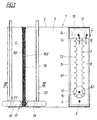
- a filter cell 1 of an electrostatic filter consists of a cell housing 2, which forms a throughflow channel 3 and an ionizing device on the inflow side 4 and on the outflow side receives a collector 5.
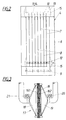
- the ionizing device 4 has in a frame 6 arranged electrodes 7, 8, which mutually Extend the distance parallel to each other across the flow cross-section and alternately consist of strip-shaped earthing plates 81 and ionizing plates 71.
- the grounding plates 81 are fixed at one end to a support rod 9 of the frame 6 pulled up and at the other end via a suspension spring 10 resiliently suspended on a suspension rod 11, whereby there is an earth connection for the frame 6 and the earthing plates 81 gives.
- the ionizing plates 71 formed with a serrated edge 72 are similar to the grounding plates firmly attached to a connecting rod 12 at one end and at the other end via a suspension spring 13 on a suspension rod 14 suspended, which ionizing plates 71 but not via the connecting rod 12 in further shown with a high voltage source in line connection stand.
- This connecting rod 12 is insulators 15 relative to the frame 6 isolated and prevent openings 82 in the grounding plates 81 an electrical contact between the grounding plates and the connecting rod.
- the flow cross-section is in the cell housing 2 as the collector 5 covering filter mat 16 made of wire wool or the like. Flows through Exhaust air the filter cell 1, the particles contained in the exhaust air through the Electric field generated in the ionizing device 4 via the electrodes 7, 8 ionized and then get to collector 5, where they are in the grounded Filter mat 16 are deposited and separated. Due to the spring-dependent elastic suspension of the electrodes 7, 8 and when in use a temperature-resistant material as a filter mat 16 is the Filter cell 1 suitable for fire and because of the filter mat as collector results Good separation performance even for high flow rates.
- the filter mat 16 is a blow-off device 17 associated with a blow-out nozzle unit 18 on the outflow side 161 the filter mat 16 and a suction hood unit 19 on the inflow side 162 the filter mat 16, the opposing blow-out nozzles and suction hood units 18, 19 by means of screw spindles 20, 21 are guided back and forth along the mat surface.
Abstract
Description
Die Erfindung bezieht sich auf ein Elektrofilter, insbesondere zur Abluftreinigung für Straßentunnel, Tiefgaragen od. dgl., aus wenigstens einer einen Durchströmkanal bildenden Filterzelle mit einer einströmseitigen lonisiereinrichtung und einem ausströmseitigen Kollektor, wobei die lonisiereinrichtung in einem Rahmen eingesetzte, sich über den Strömungsquerschnitt erstreckende Elektroden aufweist.The invention relates to an electrostatic filter, in particular for cleaning exhaust air for road tunnels, underground garages or the like, from at least one Through-flow channel-forming filter cell with an inflow-side ionizing device and an outlet-side collector, the ionizing device in inserted a frame, extending over the flow cross-section Electrodes.
Die Abluft aus einem Straßentunnel, einer Tiefgarage od. dgl. enthält feste Partikel, wie Dieselruß, Reifen- oder Straßenbelagsabrieb, Staub u. dgl., und auch Flüssigpartikel, welche Partikel aus Umweltschutzgründen oder zur Wiederverwendung der gereinigten Luft im Tunnel abgeschieden werden müssen. Mechanische Filteranlagen eignen sich dazu wenig, da sie mit großen Druckverlusten verbunden sind und wegen der anfallenden beträchtlichen Luftmengen hohe Anforderungen an die Ventilatorleistungen stellen. Für diese Abluftreinigung kommen demnach vor allem Elektrofilter zur Anwendung, die nach dem Penney-Prinzip arbeiten, wobei in einer lonisiereinrichtung über an eine hohe Gleichstromspannung angelegte Elektroden ein elektrisches Feld zur lonisierung der abzuscheidenden Partikel erzeugt wird, wodurch die geladenen Partikel anschließend in einem Kollektor unter Abgabe ihrer Ladung niederschlagbar sind. Der Kollektor setzt sich dazu bisher aus mit Abstand nebeneinander angeordneten, abwechselnd positiven und negativen Kollektorplatten zusammen, so daß die ionisierten Partikel der zwischen den Kollektorplatten hindurchströmenden Abluft je nach Ladung von den einen Kollektorplatten abgestoßen und von den anderen angezogen werden und sich durch diese Ablenkung an den sie anziehenden Kollektorplatten absetzen. Bei höheren Durchströmgeschwindigkeiten, wie sie bei den angestrebten großen Durchsatzmengen auftreten, ist allerdings die Abscheideleistung dieser Filter, vor allem hinsichtlich der extrem kleinen Rußpartikel unbefriedigend. Außerdem versagen diese Elektrofilter im Brandfall, bei dem eine Rauchabscheidung wegen der Sichtverhältnisse sehr wichtig wäre, da die Betriebstemperatur üblicherweise bei ca. 65° C liegt und die lonisiereinrichtung und der Kollektor einer einem Brandfall entsprechenden Temperaturbelastung von ca. 250° C nicht standhalten. Die beiderends fest abgestützten Elektroden bzw. Kollektorplatten unterliegen nämlich einer wärmebedingten Dehnung und verformen sich, wodurch es innerhalb kürzester Zeit zu Kurzschlüssen bzw. Überschlagsentladungen käme. Ein Ausfall der Hochspannung führt aber sofort zur Wirkungslosigkeit eines solchen Elektrofilters. Nicht zuletzt gibt es bisher bei der Reinigung des Kollektors Schwierigkeiten, denn die Kollektorplatten bedürfen immer wieder einer intensiveren Waschung, was neben dem damit verbundenen Aufwand nur bei einem Stillstehen der Filteranlage möglich ist und wegen der Notwendigkeit einer durchgreifenden Trocknung vor einer erneuten Hochspannungsbeaufschlagung recht zeitaufwendig ist.Contains the exhaust air from a road tunnel, an underground car park or the like solid particles such as diesel soot, tire or road surface abrasion, dust and. the like, and also liquid particles, which particles for environmental reasons or for Reuse of the cleaned air in the tunnel must be separated. Mechanical filter systems are not very suitable for this, since they are large Pressure drops are connected and because of the considerable incurred Air volumes place high demands on fan performance. For this Exhaust air purification is therefore mainly used for electrostatic filters work according to the Penney principle, being in a lonizer above a high dc voltage applied electrodes to an electric field Ionization of the particles to be separated is generated, whereby the charged Particles can then be deposited in a collector, giving up their charge are. So far, the collector has been placed side by side arranged, alternating positive and negative collector plates together so that the ionized particles are between the collector plates exhaust air flowing through depending on the load from the one collector plate repelled and attracted by others and by themselves Place the deflection on the collector plates that attract them. At higher Flow velocities, such as those for the large throughputs aimed for occur, however, is the separation performance of these filters, especially unsatisfactory with regard to the extremely small soot particles. Also fail these electrostatic precipitators in the event of a fire, where smoke separation because of the Visibility would be very important as the operating temperature is usually around approx. 65 ° C and the ionizing device and the collector in the event of a fire do not withstand the corresponding temperature load of approx. 250 ° C. The Both electrodes and collector plates are firmly supported namely a thermal strain and deform, leaving it inside short circuits or flashover discharges would occur in the shortest possible time. A failure of the high voltage immediately leads to the ineffectiveness of one such electrostatic precipitators. Last but not least, there is cleaning the collector Difficulties, because the collector plates always need one more intensive washing, which in addition to the effort involved a standstill of the filter system is possible and because of the need for a thorough drying before renewed exposure to high voltage is quite time consuming.
Der Erfindung liegt daher die Aufgabe zugrunde, einen Elektrofilter der eingangs geschilderten Art zu schaffen, der sich bei verhältnismäßig aufwandsarmer Bauweise durch seine hohe Abscheidewirkung und seine Brandtauglichkeit auszeichnet und der sich darüber hinaus auch rationell reinigen läßt.The invention is therefore based on the object of an electrostatic filter to create the type described above, which is relatively inexpensive Construction due to its high separation efficiency and suitability for fire distinguished and which can also be cleaned efficiently.
Die Erfindung löst diese Aufgabe dadurch, daß die Elektroden einerends fest und andernends federnd nachgiebig im Rahmen eingespannt sind und als Kollektor eine geerdete, den Strömungsquerschnitt überdeckende Filtermatte aus Drahtwolle od. dgl. vorgesehen ist. Durch die federnde Aufhängung der Elektroden können deren wärmebedingte Dehnungen verformungsfrei aufgenommen werden und auch bei höheren Temperaturen, wie sie im Brandfalle auftreten, sind keine Kurzschlüsse oder Überschlagsentladungen auf Grund sich ändernder Elektrodenabstände zu befürchten. Die Elektroden können an sich beliebig ausgestaltet sein, so lange sie ein gleichmäßig über den Strömungsquerschnitt verteiltes elektrisches Feld erzeugen, wobei vorteilhafterweise Blechstreifen aus Edelstahl als Elektroden dienen, von denen abwechselnd die einen geerdet und die anderen an einer Hochspannungsquelle angeschlossen sind und die an der Hochspannungsquelle angeschlossenen Blechstreifen gezackte Ränder für eine Spitzenionisierung bilden.The invention solves this problem in that the electrodes at one end firmly and otherwise resiliently clamped in the frame and as Collector a grounded filter mat covering the flow cross-section Wire wool or the like is provided. Due to the elastic suspension of the electrodes their thermal expansion can be absorbed without deformation and even at higher temperatures, such as those that occur in the event of a fire, are not short circuits or flashover discharges due to changing To fear electrode distances. The electrodes can be any be designed as long as they are even over the flow cross-section Generate distributed electrical field, advantageously sheet metal strips Stainless steel serve as electrodes, one of which is alternately grounded and the others are connected to a high voltage source and the others High voltage source connected jagged edges for a sheet metal strip Form peak ionization.
Da weiters der Kollektor aus einer Filtermatte besteht, brauchen die ionisierten Partikel auch nicht mehr quer zur Strömungsrichtung zu entsprechenden Kollektorplatten hin abgelenkt zu werden, denn sie müssen zwangsweise beim Durchdringen der Filtermatte mit dem geerdeten Mattenmaterial in Kontakt treten und werden so abgeschieden, wobei als Filtermaterial Drahtwolle oder ähnliches Drahtmaterial, wie Drahtgestricke und Drahtgeflechte, aber auch Faservliese u. dgl. aus Metall, Keramik, Kunststoff oder anderen geeigneten leitenden Werkstoffen, verwendet wird. Diese Filtermatte ist temperaturunempfindlich und bringt auch bei Ausfall der lonisierung durch ein Zusammenbrechen der Hochspannung als rein mechanisches Filter einen Abscheideeffekt mit sich, ohne wegen der lockereren Struktur höhere Druckverluste zu verursachen. Auf Grund des Zusammenwirkens von lonisiereinrichtung und Filtermatte sind zudem auch bei hohen Durchströmgeschwindigkeiten ausreichend gute Abscheideleistungen gewährleistet, die wegen der Temperaturbelastbarkeit der lonisiereinrichtung und des Kollektors ebenfalls weitgehend temperaturunabhängig sind.Since the collector also consists of a filter mat, they need ionized particles also no longer transverse to the flow direction to corresponding ones Collector plates to be distracted because they have to when penetrating the filter mat in contact with the earthed mat material kick and are so separated, using wire wool or similar wire material, such as wire mesh and wire mesh, but also non-woven fabrics u. Like. Made of metal, ceramic, plastic or other suitable conductive materials. This filter mat is insensitive to temperature and also brings about a breakdown if the ionization fails the high voltage as a purely mechanical filter has a separation effect, without causing higher pressure losses due to the looser structure. On The reason for the interaction of the ionizing device and the filter mat are also Sufficiently good separation performance even at high flow rates guaranteed because of the temperature resistance of the ionizing device and the collector are also largely independent of temperature.
Da die lonisiereinrichtung und der Kollektor zu einer Filterzelle zusammengefaßt sind, ist es möglich, eine solche Filterzelle für sich allein als Elektrofilter einzusetzen oder mehrere solcher Filterzellen modulartig zu einer ganzen Filteranlage zusammenzubauen, wobei die Filterzellen meist parallel nebeneinander angeordnet sind, aber auch durchaus zum Erreichen verstärkter Abscheideeffekte in Serie hintereinandergereiht sein können. Mehrere Filterzellen lassen sich auch zu einer Großfilterzelle zusammenstellen, die einen gemeinsamen Durchströmkanal bildet und in einem Rahmengehäuse einströmseitig die zu einer lonisiereinheit zusammengefaßten lonisiereinrichtungen und ausströmseitig die zu einer Kollektoreinheit zusammengefaßten Kollektoren der einzelnen Filterzellen aufnimmt.Since the ionizing device and the collector are combined to form a filter cell are, it is possible to use such a filter cell on its own as an electrostatic filter use or several such filter cells in a modular manner to assemble the entire filter system, with the filter cells mostly in parallel are arranged side by side, but also to achieve more Separation effects can be lined up in series. Multiple filter cells can also be put together to form a large filter cell that has a common Flow channel forms and in a frame housing on the inflow side to form an ionizing unit and on the outflow side the collectors of the individual combined into a collector unit Holds filter cells.
Die im wesentlichen quer zum Durchströmkanal ausgerichtete Filtermatte bietet im Vergleich zu herkömmlichen, in Strömungsrichtung ausgerichteten Kollektorplatten alle Voraussetzungen für eine rationelle Reinigung. Dazu kann nach einer vorteilhaften Ausgestaltung der Erfindung der Filtermatte eine Abblasvorrichtung zugeordnet sein, die eine Ausblasdüseneinheit an der Abströmseite der Filtermatte und eine Absaughaubeneinheit an deren Zuströmseite umfaßt, wobei die einander gegenüberliegenden Ausblasdüsen- und Absaughaubeneinheiten gemeinsam entlang der Mattenoberfläche hin- und herbewegbar geführt sind. Die Kombination von Durchblasen und Absaugen garantiert eine gründliche Säuberung der Filtermatte im Zuge einer Trockenreinigung, die durchaus auch während des Filterbetriebes möglich ist. Die entsprechend kleinere Flächenbereiche erfassenden Düsen- und Haubeneinheiten beeinträchtigen dabei den Luftdurchsatz durch das Filter kaum und führen schon bei vergleichsweise geringen Blas- und Saugdrücken zu einer flächenspezifisch hochwirksamen Reinigung.The filter mat oriented essentially transversely to the flow channel offers compared to conventional, flow-oriented Collector plates meet all the requirements for efficient cleaning. This can According to an advantageous embodiment of the invention of the filter mat, a blow-off device be assigned to a blow-off nozzle unit on the outflow side the filter mat and a suction hood unit on the inflow side thereof, the opposing blow-out nozzle and suction hood units can be moved back and forth together along the mat surface are led. The combination of blowing and suction guarantees one thorough cleaning of the filter mat in the course of dry cleaning, which is quite is also possible during filter operation. The correspondingly smaller one Impair area and nozzle units and hood units the air throughput through the filter is scarce and leads to comparative low blowing and suction pressures to a surface-specific, highly effective one Cleaning.
Erfindungsgemäß kann ferner der Filterzelle eine Wassereinsprühvorrichtung mit vor und/oder hinter der Filtermatte vorgesehenen Spritzdüsen zur zusätzlichen Luftwäsche zugehören, so daß durch den entstehenden Wassernebel oder -vorhang nicht nur die Partikelabscheidung beeinflußbar ist, sondern sich auch eine Gasabscheidung erreichen läßt. Dabei können die Spritzdüsen in Anpassung an die jeweiligen Gegebenheiten vor der lonisiereinrichtung sitzen, was beispielsweise für den Brandfall zweckmäßig ist, oder nach der lonisiereinrichtung, um den lonisiervorgang nicht zu beeinträchtigen, und sie können auch hinter dem Kollektor angeordnet sein und das Wasser gegen die Durchströmrichtung durch die Filtermatte spritzen, wodurch neben dem Wascheffekt der Abscheideeffekt erhöht und ein Filterreinigungseffekt erzielt wird.According to the invention, the filter cell can also be a water spray device with spray nozzles provided in front of and / or behind the filter mat belong to additional air washing, so that through the water mist or curtain not only can be influenced, but also gas separation can also be achieved. The spray nozzles can Adapt to the respective circumstances in front of the ionizing device, which is useful, for example, in the event of a fire or after the ionizing device, so as not to interfere with the ionizing process, and you can also be arranged behind the collector and the water against the flow direction spray through the filter mat, which in addition to the washing effect the separation effect is increased and a filter cleaning effect is achieved.
In der Zeichnung ist der Erfindungsgegenstand an Hand eines Ausführungsbeispieles rein schematisch veranschaulicht, und zwar zeigen
- Fig. 1
- eine Filterzelle eines erfindungsgemäßen Elektrofilters im Längsschnitt,
- Fig. 2
- die lonisiereinrichtung der Filterzelle in Stirnansicht und
- Fig. 3
- den Kollektor dieser Filterzelle im Querschnitt.
- Fig. 1
- a filter cell of an electrostatic filter according to the invention in longitudinal section,
- Fig. 2
- the ionizing device of the filter cell in front view and
- Fig. 3
- the collector of this filter cell in cross section.
Eine Filterzelle 1 eines Elektrofilters besteht aus einem Zellengehäuse 2, das einen Durchströmkanal 3 bildet und einströmseitig eine lonisiereinrichtung
4 und ausströmseitig einen Kollektor 5 aufnimmt. Die lonisiereinrichtung 4 weist
in einem Rahmen 6 angeordnete Elektroden 7, 8 auf, die sich mit gegenseitigem
Abstand parallel zueinander über den Strömungsquerschnitt erstrecken und abwechselnd
aus streifenförmigen Erdungsblechen 81 und lonisierblechen 71 bestehen.
Die Erdungsbleche 81 sind an ihrem einen Ende fest auf einer Trägerstange
9 des Rahmens 6 aufgezogen und am anderen Ende über eine Aufhängefeder
10 federnd nachgiebig an einer Aufhängestange 11 aufgehängt,
wobei es für den Rahmen 6 sowie die Erdungsbleche 81 einen Erdungsanschluß
gibt. Die mit einem gezackten Rand 72 ausgebildeten lonisierbleche 71 sind
ähnlich den Erdungsblechen einerends fest auf einer Anschlußstange 12 aufgezogen
und andernends über eine Aufhängefeder 13 an einer Aufhängestange 14
aufgehängt, welche lonisierbleche 71 aber über die Anschlußstange 12 in nicht
weiter dargestellter Weise mit einer Hochspannungsquelle in Leitungsverbindung
stehen. Diese Anschlußstange 12 ist über Isolatoren 15 gegenüber dem Rahmen
6 isoliert und Durchtrittsöffnungen 82 in den Erdungsblechen 81 verhindern
einen elektrischen Kontakt zwischen Erdungsblechen und Anschlußstange.A
Als Kollektor 5 ist im Zellengehäuse 2 eine den Strömungsquerschnitt
überdeckende Filtermatte 16 aus Drahtwolle od. dgl. eingesetzt. Durchströmt
Abluft die Filterzelle 1, werden die in der Abluft enthaltenen Partikel durch das
über die Elektroden 7, 8 in der lonisiereinrichtung 4 erzeugte elektrische Feld
ionisiert und gelangen anschließend zum Kollektor 5, wo sie in der geerdeten
Filtermatte 16 niedergeschlagen und abgeschieden werden. Auf Grund der
federbedingt dehnungsfähigen Aufhängung der Elektroden 7, 8 und bei Verwendung
eines temperaturbeständigen Materials als Filtermatte 16 ist die
Filterzelle 1 brandtauglich und wegen der Filtermatte als Kollektor ergibt sich
auch für hohe Durchströmgeschwindigkeiten eine gute Abscheideleistung. The flow cross-section is in the
Zur Reinigung des Kollektors 5 ist der Filtermatte 16 eine Abblasvorrichtung
17 zugeordnet, die eine Ausblasdüseneinheit 18 an der Abströmseite 161
der Filtermatte 16 und eine Absaughaubeneinheit 19 an der Zuströmseite 162
der Filtermatte 16 umfaßt, wobei die einander gegenüberliegenden Ausblasdüsen-
und Absaughaubeneinheiten 18, 19 mittels Schraubenspindeln 20, 21
entlang der Mattenoberfläche hin- und herbewegbar geführt sind. Durch diese
Blas-Saugreinigung ergibt sich eine hohe Reinigungswirkung und die Filtermattenreinigung
kann auch während des Filterbetriebes erfolgen, so daß von vornherein
größere Verschmutzungen der Filtermatte und damit entsprechend
steigende Druckverluste vermeidbar sind.To clean the
Claims (3)
Priority Applications (1)
| Application Number | Priority Date | Filing Date | Title |
|---|---|---|---|
| AT00890063T ATE405349T1 (en) | 1999-03-01 | 2000-03-01 | ELECTRICAL FILTER, ESPECIALLY FOR AIR CLEANING FOR ROAD TUNNELS, UNDERGROUND CARARIES OR. DGL. |
Applications Claiming Priority (2)
| Application Number | Priority Date | Filing Date | Title |
|---|---|---|---|
| AT0033199A AT406737B (en) | 1999-03-01 | 1999-03-01 | ELECTRIC FILTERS, ESPECIALLY FOR EXHAUST AIR CLEANING FOR ROAD TUNNELS, UNDERGROUND GARAGES OD. DGL. |
| AT33199 | 1999-03-01 |
Publications (3)
| Publication Number | Publication Date |
|---|---|
| EP1033171A2 true EP1033171A2 (en) | 2000-09-06 |
| EP1033171A3 EP1033171A3 (en) | 2001-03-28 |
| EP1033171B1 EP1033171B1 (en) | 2008-08-20 |
Family
ID=3487763
Family Applications (1)
| Application Number | Title | Priority Date | Filing Date |
|---|---|---|---|
| EP00890063A Expired - Lifetime EP1033171B1 (en) | 1999-03-01 | 2000-03-01 | Electrostatic filter, especially for cleaning exhaust air in vehicular tunnels, subterranean garages and the like |
Country Status (3)
| Country | Link |
|---|---|
| EP (1) | EP1033171B1 (en) |
| AT (2) | AT406737B (en) |
| DE (1) | DE50015313D1 (en) |
Cited By (2)
| Publication number | Priority date | Publication date | Assignee | Title |
|---|---|---|---|---|
| DE102018209993A1 (en) | 2018-06-20 | 2019-12-24 | ECOVAC Filteranlagen GmbH | Device and method for cleaning polluted air |
| WO2020234472A1 (en) | 2019-05-22 | 2020-11-26 | Kronhagel, Christoph | Air purification system |
Families Citing this family (4)
| Publication number | Priority date | Publication date | Assignee | Title |
|---|---|---|---|---|
| DE102011110805B4 (en) | 2011-08-15 | 2019-02-14 | Peter Oertmann | Electronic fine dust separator |
| DE202011104657U1 (en) | 2011-08-15 | 2011-11-18 | Peter Oertmann | Electronic fine dust separator |
| WO2013023644A1 (en) | 2011-08-15 | 2013-02-21 | Peter Oertmann | Electronic fine dust separator |
| DE202021002126U1 (en) | 2021-06-18 | 2021-07-05 | Reinhard Stiebert | Arrangement for filtering and disinfecting breathing air within protective masks, protective shields and other devices for the passage of breathing air by means of electrostatic filter structures and / or plasma units and additional components |
Citations (11)
| Publication number | Priority date | Publication date | Assignee | Title |
|---|---|---|---|---|
| FR865813A (en) * | 1939-06-21 | 1941-06-05 | Louis Prat Soc | Improvements to devices for electrostatic dust collection |
| GB553753A (en) * | 1941-12-12 | 1943-06-03 | Vauxhall Motors Ltd | Improved electrostatic gas cleaner |
| US4029482A (en) * | 1974-03-27 | 1977-06-14 | Battelle Memorial Institute | Electrostatic removal of airborne particulates employing fiber beds |
| US4147522A (en) * | 1976-04-23 | 1979-04-03 | American Precision Industries Inc. | Electrostatic dust collector |
| US4222748A (en) * | 1979-02-22 | 1980-09-16 | Monsanto Company | Electrostatically augmented fiber bed and method of using |
| EP0039669A2 (en) * | 1980-05-06 | 1981-11-11 | Fleck, Carl Maria, Prof. Dr. | Electrostatic air filter |
| US4666474A (en) * | 1986-08-11 | 1987-05-19 | Amax Inc. | Electrostatic precipitators |
| WO1993016807A1 (en) * | 1992-02-20 | 1993-09-02 | Tl-Vent Ab | A two-stage electrostatic filter |
| DE4207022A1 (en) * | 1992-03-06 | 1993-09-09 | Rolf Hertfelder | ELECTROSTATIC FILTER DEVICE FOR COOKER HOODS |
| US5391222A (en) * | 1993-04-15 | 1995-02-21 | The Babcock & Wilcox Company | In place discharge electrode replacement on rigid frame ESP's |
| US5698012A (en) * | 1995-03-28 | 1997-12-16 | Ajiawasu Kabushiki Kaisha | Exhaust gas purifying apparatus |
-
1999
- 1999-03-01 AT AT0033199A patent/AT406737B/en not_active IP Right Cessation
-
2000
- 2000-03-01 EP EP00890063A patent/EP1033171B1/en not_active Expired - Lifetime
- 2000-03-01 AT AT00890063T patent/ATE405349T1/en not_active IP Right Cessation
- 2000-03-01 DE DE50015313T patent/DE50015313D1/en not_active Expired - Fee Related
Patent Citations (11)
| Publication number | Priority date | Publication date | Assignee | Title |
|---|---|---|---|---|
| FR865813A (en) * | 1939-06-21 | 1941-06-05 | Louis Prat Soc | Improvements to devices for electrostatic dust collection |
| GB553753A (en) * | 1941-12-12 | 1943-06-03 | Vauxhall Motors Ltd | Improved electrostatic gas cleaner |
| US4029482A (en) * | 1974-03-27 | 1977-06-14 | Battelle Memorial Institute | Electrostatic removal of airborne particulates employing fiber beds |
| US4147522A (en) * | 1976-04-23 | 1979-04-03 | American Precision Industries Inc. | Electrostatic dust collector |
| US4222748A (en) * | 1979-02-22 | 1980-09-16 | Monsanto Company | Electrostatically augmented fiber bed and method of using |
| EP0039669A2 (en) * | 1980-05-06 | 1981-11-11 | Fleck, Carl Maria, Prof. Dr. | Electrostatic air filter |
| US4666474A (en) * | 1986-08-11 | 1987-05-19 | Amax Inc. | Electrostatic precipitators |
| WO1993016807A1 (en) * | 1992-02-20 | 1993-09-02 | Tl-Vent Ab | A two-stage electrostatic filter |
| DE4207022A1 (en) * | 1992-03-06 | 1993-09-09 | Rolf Hertfelder | ELECTROSTATIC FILTER DEVICE FOR COOKER HOODS |
| US5391222A (en) * | 1993-04-15 | 1995-02-21 | The Babcock & Wilcox Company | In place discharge electrode replacement on rigid frame ESP's |
| US5698012A (en) * | 1995-03-28 | 1997-12-16 | Ajiawasu Kabushiki Kaisha | Exhaust gas purifying apparatus |
Cited By (2)
| Publication number | Priority date | Publication date | Assignee | Title |
|---|---|---|---|---|
| DE102018209993A1 (en) | 2018-06-20 | 2019-12-24 | ECOVAC Filteranlagen GmbH | Device and method for cleaning polluted air |
| WO2020234472A1 (en) | 2019-05-22 | 2020-11-26 | Kronhagel, Christoph | Air purification system |
Also Published As
| Publication number | Publication date |
|---|---|
| AT406737B (en) | 2000-08-25 |
| DE50015313D1 (en) | 2008-10-02 |
| EP1033171A3 (en) | 2001-03-28 |
| EP1033171B1 (en) | 2008-08-20 |
| ATA33199A (en) | 2000-01-15 |
| ATE405349T1 (en) | 2008-09-15 |
Similar Documents
| Publication | Publication Date | Title |
|---|---|---|
| DE19650585C2 (en) | Method and device for electrically charging and separating particles that are difficult to separate from a gas fluid | |
| DE102004022288B4 (en) | Electrostatic separator with internal power supply | |
| EP0092854B1 (en) | Wet electrofilter for a converter exhaust | |
| DE2810735C2 (en) | Electric gas cleaning device | |
| DE3122515C2 (en) | Electrostatic filter assembly | |
| CH574274A5 (en) | Electrostatic dust precipitator - with multiple plane electrodes axially parallel to air flow | |
| DE2143280A1 (en) | Electrostatic air filter | |
| WO2003008104A1 (en) | Unit fort the electrostatic scrubbing of gas and method for operation thereof | |
| EP2244834A1 (en) | Electrostatic precipitator | |
| US4293319A (en) | Electrostatic precipitator apparatus using liquid collection electrodes | |
| DE2822456A1 (en) | DEVICE AND METHOD FOR NEUTRALIZING ELECTRICALLY CHARGED FLOATING PARTICLES | |
| EP1976639B1 (en) | Apparatus for purifying air, in particular for ventilation and air-conditioning systems | |
| DE2116566A1 (en) | Electrostatic separation system | |
| EP1926558A1 (en) | Electrostatic ionisation stage in an elimination device | |
| DE102011052946B4 (en) | electrostatic | |
| AT406737B (en) | ELECTRIC FILTERS, ESPECIALLY FOR EXHAUST AIR CLEANING FOR ROAD TUNNELS, UNDERGROUND GARAGES OD. DGL. | |
| WO2002066167A1 (en) | Electrostatic dust separator with integrated filter tubing | |
| EP2189223A1 (en) | Wet cleaning electric filter for cleaning exhaust gas and method suitable for this | |
| EP1771254B1 (en) | Structural principle of an exhaust gas purification installation, and associated method for purifying an exhaust gas | |
| DE838594C (en) | Collector for electric gas purifiers | |
| DE3802748A1 (en) | Electrostatic filter for purificn. of air - has collector of open pored material with electrically conductive surface layer | |
| DE102006033945B4 (en) | Controlling the high voltage of an electric air filter device | |
| JP3973764B2 (en) | Electric dust collector | |
| DE19841973C2 (en) | Electro filter stage made up of spray electrodes and a precipitation electrode | |
| DE2216436A1 (en) | Dust filter device |
Legal Events
| Date | Code | Title | Description |
|---|---|---|---|
| PUAI | Public reference made under article 153(3) epc to a published international application that has entered the european phase |
Free format text: ORIGINAL CODE: 0009012 |
|
| AK | Designated contracting states |
Kind code of ref document: A2 Designated state(s): AT BE CH CY DE DK ES FI FR GB GR IE IT LI LU MC NL PT SE |
|
| AX | Request for extension of the european patent |
Free format text: AL;LT;LV;MK;RO;SI |
|
| PUAL | Search report despatched |
Free format text: ORIGINAL CODE: 0009013 |
|
| AK | Designated contracting states |
Kind code of ref document: A3 Designated state(s): AT BE CH CY DE DK ES FI FR GB GR IE IT LI LU MC NL PT SE |
|
| AX | Request for extension of the european patent |
Free format text: AL;LT;LV;MK;RO;SI |
|
| 17P | Request for examination filed |
Effective date: 20010830 |
|
| AKX | Designation fees paid |
Free format text: AT BE CH CY DE DK ES FI FR GB GR IE IT LI LU MC NL PT SE |
|
| 17Q | First examination report despatched |
Effective date: 20070322 |
|
| GRAP | Despatch of communication of intention to grant a patent |
Free format text: ORIGINAL CODE: EPIDOSNIGR1 |
|
| GRAS | Grant fee paid |
Free format text: ORIGINAL CODE: EPIDOSNIGR3 |
|
| GRAA | (expected) grant |
Free format text: ORIGINAL CODE: 0009210 |
|
| AK | Designated contracting states |
Kind code of ref document: B1 Designated state(s): AT BE CH CY DE DK ES FI FR GB GR IE IT LI LU MC NL PT SE |
|
| REG | Reference to a national code |
Ref country code: GB Ref legal event code: FG4D Free format text: NOT ENGLISH |
|
| REG | Reference to a national code |
Ref country code: CH Ref legal event code: EP |
|
| REG | Reference to a national code |
Ref country code: IE Ref legal event code: FG4D Free format text: LANGUAGE OF EP DOCUMENT: GERMAN |
|
| REF | Corresponds to: |
Ref document number: 50015313 Country of ref document: DE Date of ref document: 20081002 Kind code of ref document: P |
|
| PG25 | Lapsed in a contracting state [announced via postgrant information from national office to epo] |
Ref country code: ES Free format text: LAPSE BECAUSE OF FAILURE TO SUBMIT A TRANSLATION OF THE DESCRIPTION OR TO PAY THE FEE WITHIN THE PRESCRIBED TIME-LIMIT Effective date: 20081201 Ref country code: NL Free format text: LAPSE BECAUSE OF FAILURE TO SUBMIT A TRANSLATION OF THE DESCRIPTION OR TO PAY THE FEE WITHIN THE PRESCRIBED TIME-LIMIT Effective date: 20080820 |
|
| PG25 | Lapsed in a contracting state [announced via postgrant information from national office to epo] |
Ref country code: FI Free format text: LAPSE BECAUSE OF FAILURE TO SUBMIT A TRANSLATION OF THE DESCRIPTION OR TO PAY THE FEE WITHIN THE PRESCRIBED TIME-LIMIT Effective date: 20080820 |
|
| REG | Reference to a national code |
Ref country code: IE Ref legal event code: FD4D |
|
| PG25 | Lapsed in a contracting state [announced via postgrant information from national office to epo] |
Ref country code: DK Free format text: LAPSE BECAUSE OF FAILURE TO SUBMIT A TRANSLATION OF THE DESCRIPTION OR TO PAY THE FEE WITHIN THE PRESCRIBED TIME-LIMIT Effective date: 20080820 Ref country code: IE Free format text: LAPSE BECAUSE OF FAILURE TO SUBMIT A TRANSLATION OF THE DESCRIPTION OR TO PAY THE FEE WITHIN THE PRESCRIBED TIME-LIMIT Effective date: 20080820 |
|
| PG25 | Lapsed in a contracting state [announced via postgrant information from national office to epo] |
Ref country code: PT Free format text: LAPSE BECAUSE OF FAILURE TO SUBMIT A TRANSLATION OF THE DESCRIPTION OR TO PAY THE FEE WITHIN THE PRESCRIBED TIME-LIMIT Effective date: 20090120 |
|
| PLBE | No opposition filed within time limit |
Free format text: ORIGINAL CODE: 0009261 |
|
| STAA | Information on the status of an ep patent application or granted ep patent |
Free format text: STATUS: NO OPPOSITION FILED WITHIN TIME LIMIT |
|
| 26N | No opposition filed |
Effective date: 20090525 |
|
| PG25 | Lapsed in a contracting state [announced via postgrant information from national office to epo] |
Ref country code: IT Free format text: LAPSE BECAUSE OF FAILURE TO SUBMIT A TRANSLATION OF THE DESCRIPTION OR TO PAY THE FEE WITHIN THE PRESCRIBED TIME-LIMIT Effective date: 20080820 |
|
| BERE | Be: lapsed |
Owner name: AIGNER, HEINZ Effective date: 20090331 |
|
| PG25 | Lapsed in a contracting state [announced via postgrant information from national office to epo] |
Ref country code: MC Free format text: LAPSE BECAUSE OF NON-PAYMENT OF DUE FEES Effective date: 20090331 |
|
| REG | Reference to a national code |
Ref country code: CH Ref legal event code: PL |
|
| GBPC | Gb: european patent ceased through non-payment of renewal fee |
Effective date: 20090301 |
|
| REG | Reference to a national code |
Ref country code: FR Ref legal event code: ST Effective date: 20091130 |
|
| PG25 | Lapsed in a contracting state [announced via postgrant information from national office to epo] |
Ref country code: CH Free format text: LAPSE BECAUSE OF NON-PAYMENT OF DUE FEES Effective date: 20090331 Ref country code: SE Free format text: LAPSE BECAUSE OF FAILURE TO SUBMIT A TRANSLATION OF THE DESCRIPTION OR TO PAY THE FEE WITHIN THE PRESCRIBED TIME-LIMIT Effective date: 20081120 Ref country code: LI Free format text: LAPSE BECAUSE OF NON-PAYMENT OF DUE FEES Effective date: 20090331 Ref country code: DE Free format text: LAPSE BECAUSE OF NON-PAYMENT OF DUE FEES Effective date: 20091001 |
|
| PG25 | Lapsed in a contracting state [announced via postgrant information from national office to epo] |
Ref country code: BE Free format text: LAPSE BECAUSE OF NON-PAYMENT OF DUE FEES Effective date: 20090331 |
|
| PG25 | Lapsed in a contracting state [announced via postgrant information from national office to epo] |
Ref country code: GB Free format text: LAPSE BECAUSE OF NON-PAYMENT OF DUE FEES Effective date: 20090301 Ref country code: FR Free format text: LAPSE BECAUSE OF NON-PAYMENT OF DUE FEES Effective date: 20091123 |
|
| PG25 | Lapsed in a contracting state [announced via postgrant information from national office to epo] |
Ref country code: AT Free format text: LAPSE BECAUSE OF NON-PAYMENT OF DUE FEES Effective date: 20090301 |
|
| PG25 | Lapsed in a contracting state [announced via postgrant information from national office to epo] |
Ref country code: GR Free format text: LAPSE BECAUSE OF FAILURE TO SUBMIT A TRANSLATION OF THE DESCRIPTION OR TO PAY THE FEE WITHIN THE PRESCRIBED TIME-LIMIT Effective date: 20081121 |
|
| PG25 | Lapsed in a contracting state [announced via postgrant information from national office to epo] |
Ref country code: LU Free format text: LAPSE BECAUSE OF NON-PAYMENT OF DUE FEES Effective date: 20090301 |
|
| PG25 | Lapsed in a contracting state [announced via postgrant information from national office to epo] |
Ref country code: CY Free format text: LAPSE BECAUSE OF FAILURE TO SUBMIT A TRANSLATION OF THE DESCRIPTION OR TO PAY THE FEE WITHIN THE PRESCRIBED TIME-LIMIT Effective date: 20080820 |