EP1035680A2 - Signal transmission system - Google Patents
Signal transmission system Download PDFInfo
- Publication number
- EP1035680A2 EP1035680A2 EP00300950A EP00300950A EP1035680A2 EP 1035680 A2 EP1035680 A2 EP 1035680A2 EP 00300950 A EP00300950 A EP 00300950A EP 00300950 A EP00300950 A EP 00300950A EP 1035680 A2 EP1035680 A2 EP 1035680A2
- Authority
- EP
- European Patent Office
- Prior art keywords
- optical
- carrier
- optical carrier
- absence
- gain control
- Prior art date
- Legal status (The legal status is an assumption and is not a legal conclusion. Google has not performed a legal analysis and makes no representation as to the accuracy of the status listed.)
- Granted
Links
Images

Classifications
-
- H—ELECTRICITY
- H04—ELECTRIC COMMUNICATION TECHNIQUE
- H04B—TRANSMISSION
- H04B10/00—Transmission systems employing electromagnetic waves other than radio-waves, e.g. infrared, visible or ultraviolet light, or employing corpuscular radiation, e.g. quantum communication
- H04B10/29—Repeaters
- H04B10/291—Repeaters in which processing or amplification is carried out without conversion of the main signal from optical form
- H04B10/293—Signal power control
- H04B10/294—Signal power control in a multiwavelength system, e.g. gain equalisation
- H04B10/296—Transient power control, e.g. due to channel add/drop or rapid fluctuations in the input power
-
- H—ELECTRICITY
- H04—ELECTRIC COMMUNICATION TECHNIQUE
- H04B—TRANSMISSION
- H04B10/00—Transmission systems employing electromagnetic waves other than radio-waves, e.g. infrared, visible or ultraviolet light, or employing corpuscular radiation, e.g. quantum communication
- H04B10/07—Arrangements for monitoring or testing transmission systems; Arrangements for fault measurement of transmission systems
- H04B10/075—Arrangements for monitoring or testing transmission systems; Arrangements for fault measurement of transmission systems using an in-service signal
- H04B10/077—Arrangements for monitoring or testing transmission systems; Arrangements for fault measurement of transmission systems using an in-service signal using a supervisory or additional signal
- H04B10/0773—Network aspects, e.g. central monitoring of transmission parameters
-
- H—ELECTRICITY
- H04—ELECTRIC COMMUNICATION TECHNIQUE
- H04B—TRANSMISSION
- H04B10/00—Transmission systems employing electromagnetic waves other than radio-waves, e.g. infrared, visible or ultraviolet light, or employing corpuscular radiation, e.g. quantum communication
- H04B10/07—Arrangements for monitoring or testing transmission systems; Arrangements for fault measurement of transmission systems
- H04B10/075—Arrangements for monitoring or testing transmission systems; Arrangements for fault measurement of transmission systems using an in-service signal
- H04B10/079—Arrangements for monitoring or testing transmission systems; Arrangements for fault measurement of transmission systems using an in-service signal using measurements of the data signal
- H04B10/0795—Performance monitoring; Measurement of transmission parameters
- H04B10/07955—Monitoring or measuring power
-
- H—ELECTRICITY
- H04—ELECTRIC COMMUNICATION TECHNIQUE
- H04J—MULTIPLEX COMMUNICATION
- H04J14/00—Optical multiplex systems
- H04J14/02—Wavelength-division multiplex systems
- H04J14/0201—Add-and-drop multiplexing
- H04J14/0202—Arrangements therefor
- H04J14/021—Reconfigurable arrangements, e.g. reconfigurable optical add/drop multiplexers [ROADM] or tunable optical add/drop multiplexers [TOADM]
- H04J14/0212—Reconfigurable arrangements, e.g. reconfigurable optical add/drop multiplexers [ROADM] or tunable optical add/drop multiplexers [TOADM] using optical switches or wavelength selective switches [WSS]
-
- H—ELECTRICITY
- H04—ELECTRIC COMMUNICATION TECHNIQUE
- H04J—MULTIPLEX COMMUNICATION
- H04J14/00—Optical multiplex systems
- H04J14/02—Wavelength-division multiplex systems
- H04J14/0221—Power control, e.g. to keep the total optical power constant
-
- H—ELECTRICITY
- H04—ELECTRIC COMMUNICATION TECHNIQUE
- H04J—MULTIPLEX COMMUNICATION
- H04J14/00—Optical multiplex systems
- H04J14/02—Wavelength-division multiplex systems
- H04J14/0278—WDM optical network architectures
- H04J14/0283—WDM ring architectures
-
- H—ELECTRICITY
- H04—ELECTRIC COMMUNICATION TECHNIQUE
- H04B—TRANSMISSION
- H04B2210/00—Indexing scheme relating to optical transmission systems
- H04B2210/07—Monitoring an optical transmission system using a supervisory signal
- H04B2210/078—Monitoring an optical transmission system using a supervisory signal using a separate wavelength
Landscapes
- Engineering & Computer Science (AREA)
- Computer Networks & Wireless Communication (AREA)
- Signal Processing (AREA)
- Physics & Mathematics (AREA)
- Electromagnetism (AREA)
- Optical Communication System (AREA)
- Small-Scale Networks (AREA)
Abstract
Description
- This invention relates to a signal transmission system, and more particularly to systems in which an optical carrier is used to carry data traffic. A number of optical carriers, each having a different wavelength, can be sent from an optical transmitter to an optical receiver via a light guide - such a technique is termed wavelength division multiplex (WDM), and each optical carrier able to carry traffic is commonly termed a channel.
- Optical Add/drop Multiplexers (OADMs) and Optical Cross-connect Switches (OXCs), both of which comprise an optical switching unit, carry multiple traffic signals on the optical channels which are transmitted or received each on a different wavelength via one or a pair of optical fibres. Each OADM and OXC has at least two such wavelength division multiplexed (WDM) ports which can be configured to insert and extract signals from and to tributary ports or to pass signals straight through from one WDM port to another.
- A common configuration for a network of OADMs or OXCs is a closed ring because it offers an alternative path for every connection allowing protection against failure of the optical fibre. In order to compensate for the loss of the interconnecting fibres and of the optical components within the OADM or OXC, it contains optical amplifiers. In a system containing amplification and a feedback path, the loop gain must be maintained at less than unity as otherwise unwanted oscillation will occur.
- Under fault conditions, the loop gain of the ring may rise above unity, causing instability and malfunction of the ring. The present invention seeks to provide a signal transmission system in which this difficulty is reduced.
- According to this invention, a signal transmission system having a plurality of WDM optical carriers, includes a plurality of optical switching units connected in a ring, means present at an optical switching unit for detecting the presence or absence of each individual optical carrier; and means responsive to the detection of the absence of an optical carrier for controlling the ring gain of that optical carrier to be less than unity.
- Oscillation in one optical channel, which can be induced by automatic gain control in the absence of an optical carrier, can adversely affect other optical channels due to non-linear effects, power hogging in the amplifiers and crosstalk from the possibly high power oscillation. Even if the loop gain of the ring is less than unity Amplifier Spontaneous Emission (ASE) can accumulate in channels not carrying a normal optical signal to a level which can interfere with adjacent channels.
- The optical switching unit may be an OADM or an OXC or other equivalent, and the following discussion of OADMs is applicable to such equivalents.
- In OADMs which may be reconfigured (i.e. changes in the channels added, dropped and passed through) some degree of automatic gain control (AGC) is advisable to maintain the power of individual optical channels at a substantially fixed level. Precautions should be taken to ensure that operation of the AGC does not raise the overall gain of any optical channel to a value where oscillation or a disruptive level of ASE accumulation occurs under any conditions. Transient effects can also be a significant problem in linear and ring networks of OADMs resulting from both deliberate changes in the number of channels being carried and during fault conditions. Consider the case when a channel has no optical signal present on it. The AGC function on that channel at each OADM would set itself to maximum gain/minimum loss in an attempt to maintain the power level. When a signal is turned on for that channel the gain at each OADM will be higher than required until the AGC control loops have time to respond. During this transient this signal at each OADM will be raised to an increasingly high level at which it will hog the available power of the optical amplifiers, reducing the signal levels of pre-existing channels and adversely affecting the traffic on them. The transient exists until the AGC control loops settle to their target output powers and optical amplifier control loops accommodate to the increased total output power. While this effect can be partially alleviated by slowly ramping up the power of the new optical signal source this places constraints on the time constants of the varius amplifier and AGC control loops. Under fault conditions ramping up the power of the source may not be possible.
- These difficulties are reduced by the present invention.
- The invention is further described by way of example with reference to the accompanying drawings, in which:-
- Figure 1 shows part of a signal transmission system in accordance with the present invention, and
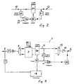
- Figures 2 and 3 show alternative configurations of part of the system in greater detail.
-
- Referring to Figure 1, there is shown therein just part of a signal transmission system in which a plurality of optical switching units comprising OADMs and OXCs are connected in a bidirectional closed ring. Only a single optical switching unit is shown. The figure illustrates just one unidirectional signal path for a WDM optical signal from one
input WDM port 1 to oneWDM output port 2 via anoptical switch 3, which can be part of an OADM or an OXC as the case may be. In practice, an OADM would usually have the same configuration repeated so as to also carry signals in the opposite direction to that illustrated. OXCs will usually have a multiplicity of input and output ports interconnected by a more complicated optical switch. - The system is first described assuming that it operates under fault-free conditions. The
input port 1 is connected to anAGC arrangement 4 which maintains a constant power per channel (i.e. optical wavelength) atpoint 5 independently of the input power per channel atport 1. Typically the input signal atport 1 contains at least eight optical channels, each at a different optical wavelength. The AGC arrangement can take the form disclosed in our copending patent application (P/61751). An optical amplifier 6 operates in a gain controlled regime having a flat frequency response so as to amplify each optical channel equally, thereby giving a constant power per channel at point 7. An optical demultiplexer 8 separates the optical channels by wavelength onto individual optical waveguides 9 for cross connection by means of theoptical switch 3. Input andoutput ports 16 of the optical switch allow channels to be added or dropped. The outputs of theoptical switch 3 will be from different inputs depending on configuration so that the optical power perchannel point 10 has some variation. A further AGC arrangement 11 maintains a constant power per channel atpoints 12. - These channels are combined into a WDM signal by
optical multiplexer 13. The loss, or signal attenuation introduced by themultiplexer 13 is substantially constant for each optical channel andoptical amplifier 14 operates in a gain-controlled regime so that the optical power per channel at theoutput port 2 is maintained substantially constant. The combined effect of theAGC arrangements 4 and 11 and gain-controlledamplifiers 6 and 14 ensures that the gain from the output of one OADM (one OADM being shown in Figure 1) through a section of interconnectingfibre 15 to the output of the next OADM is nominally unity with a small spread. Where traffic is carried in a ring there must be at least two nodes (the nodes sourcing and sinking the traffic) where the optical switches are in the add/drop configuration. The through loss of the switch in the add/drop configuration is large, typically 30 dB, which, for both nodes means that the loop gain is reduced by 60 d8. This is very much greater than the worst case sum of gain spread above nominal for all hops in the ring. The loop gain of the ring is therefore guaranteed to be much less than unity. -
Port 1 also receives a supervisory optical channel which does not carry traffic, and is used for signalling and management purposes. This is extracted by the supervisorychannel extract unit 17, and its signalling information routed to controllogic 18, which is linked to the operation of theoptical switch 3, and the AGC arrangements 11. One function of the control logic is described in connection with Figure 3. Thecontrol logic 18 reformats the supervisory channel and inserts it by a supervisory channel insertunit 19 onto theoutput port 2. - Considering fault conditions, should the source of an optical signal fail, AGC arrangement 11 forming part of that channel would increase its gain in an attempt to maintain a constant power at
point 12. This would happen at each OADM in the ring subsequent to the failure so that the through gain for this failed channel would be substantially increased, say by X dB. The overall loop gain in a ring of N OADMs would be increased by N x X dB. As an example, take - In order to avoid this difficulty, the AGC arrangement 11 includes means of detecting that its input optical signal is absent, and in response to that overrides the gain control mechanism to set it to minimum gain. Figures 2 and 3 show alternative arrangements for achieving this condition.
- Referring to Figure 2, the
input port 10 is connected to theoutput port 12 via a variable gain/loss device 20. Theport 12 is also connected via anoptical power detector 21 to acontrol unit 22 which adjusts the gain or loss of thedevice 20, so as to comprise a feedback loop. An additionaloptical power detector 23 at theinput port 10 feeds athreshold detector 24, such that when the optical power level atport 10 falls below a threshold value (the fail condition) the output of acomparator 24 changes state. The threshold value is set by thereference input 25 and it is this threshold which determines the level at which an input channel is present or absent. If necessary, the threshold can be adjusted to determine an optimum level for reliability of operation.. Thecomparator 24 provides an additional input to thecontrol unit 22 to disable the feedback loop, and to force the variable gain/loss device 20 to its lowest gain or maximum loss. In practice, thedevice 20 may be a variable gain amplifier having a gain characteristic which is flat across the wavelength band of interest, or alternatively it can be a variable attenuator followed by a preset-gain amplifier. - Referring to Figure 3, an alternative arrangement is shown which avoids the need for the second
optical detector 23 of Figure 2. In addition to illustrating the AGC arrangement 11, it shows modifications to the optical switching unit of Figure 1. A feedback loop comprises a variable gain/loss device 30, anoptical power detector 31, and acontrol unit 32, in a manner similar to Figure 2. Theoptical detector 31 is coupled to one input of a comparator 33 whose output changes state to the fail condition if the optical power atpoint 12 is less than the value the AGC loop is attempting to be maintain. This mechanism cannot be used directly to set the AGC loop to minimum gain/max loss because recovery from this condition would not be possible. The fail condition is signalled to the next OADM in the ring via asupervisory channel transmitter 34. The supervisory channel may be carried on an optical channel additional to those carrying traffic, known as an optical supervisory channel, or by other means. The next OADM on the ring extracts the signalled condition of the optical channels by means of thesupervisory channel receiver 17 and by knowledge of the configuration of the optical switch can determine incontrol logic 18 whether the failed optical channel is connected to one of its variable gain/loss devices 30. If it is, thecontrol logic 18 overrides the AGC loss forcing it to set the variable gain/loss device 30 to lowest gain/maximum loss. The fault condition is signalled on to the next OADM as before on the supervisory channel via the supervisorychannel insert unit 34. - The result is that the AGC arrangement 11 in the first OADM which detects the fail condition sets to highest gain/minimum loss but all AGC arrangements 11 for this failed channel in subsequent OADMs are set to lowest gain/maximum loss. The overall gain around the ring is therefore held substantially less than unity.
- In both Figures 2 and 3 the variable gain/loss element may be an optical amplifier (Semiconductor Optical Amplifier, or Erbium Doped Fibre Amplifier) or an electrically controlled optical attenuator.
- Both of these solutions also greatly reduce the effect of transient power changes since at most one OADM, or other optical switching unit, is operating at maximum gain and all subsequent OADMs operate at maximum loss until after the new signal is applied. The speed of the AGC control loop is designed so that when the new signal is detected it ramps up the amplitude sufficiently slowly to allow the optical amplifiers to accommodate to the increasing output power required without affecting the pre-existing channels.
Claims (10)
- A signal transmission system having a plurality of WDM optical carriers, including a plurality of optical switching units connected in a ring, means present at an optical switching unit for detecting the presence or absence of each individual optical carrier; and means responsive to the detection of the absence of an optical carrier for controlling the ring gain of that optical carrier to be less than unity.
- A system as claimed in Claim 1 and wherein each optical switching unit includes a channel multiplexer, and said means for detecting the presence or absence of an optical carrier is positioned in an input channel path of said multiplexer.
- A system as claimed in Claim 2, and wherein a said means for detecting the presence or absence of an optical carrier is positioned in every input channel path of said multiplexer.
- A system as claimed in any of the preceding claims and wherein an automatic gain control arrangement is provided to adjust the level of an optical carrier which is detected as being present.
- A system as claimed in Claim 4 and wherein said automatic gain control arrangement is disabled when an optical carrier is detected as being absent, so as to permit the gain of the channel of that optical carrier to be reduced.
- A system as claimed in Claim 4 or 5 and wherein said automatic gain control arrangement includes a variable gain optical amplifier.
- A system as claimed in Claim 4 or 5 and wherein said automatic gain control arrangement includes a variable optical attenuator.
- A system as claimed in Claim 4 or 5 and wherein means are provided to detect the presence or absence of an input to the automatic gain control arrangement for each optical carrier.
- A system as claimed in Claim 4 or 5 and wherein an optical detector forming part of the automatic gain control arrangement forms part of the means for detecting the presence or absence of an optical carrier, and wherein detection of an absence is signalled to the next optical switching unit in the ring to cause it to reduce its optical gain for that carrier.
- A system as claimed in Claim 4, and wherein the control loop speed of the automatic gain control arrangement is made sufficiently slow to avoid power hogging by an optical carrier suffering transient disturbances.
Applications Claiming Priority (2)
| Application Number | Priority Date | Filing Date | Title |
|---|---|---|---|
| GB9905731A GB2347809B (en) | 1999-03-12 | 1999-03-12 | Signal transmission system |
| GB9905731 | 1999-03-12 |
Publications (3)
| Publication Number | Publication Date |
|---|---|
| EP1035680A2 true EP1035680A2 (en) | 2000-09-13 |
| EP1035680A3 EP1035680A3 (en) | 2005-10-05 |
| EP1035680B1 EP1035680B1 (en) | 2012-04-11 |
Family
ID=10849527
Family Applications (1)
| Application Number | Title | Priority Date | Filing Date |
|---|---|---|---|
| EP00300950A Expired - Lifetime EP1035680B1 (en) | 1999-03-12 | 2000-02-07 | Signal transmission system |
Country Status (12)
| Country | Link |
|---|---|
| US (1) | US6515777B1 (en) |
| EP (1) | EP1035680B1 (en) |
| JP (1) | JP4237373B2 (en) |
| CN (1) | CN1192533C (en) |
| AT (1) | ATE553556T1 (en) |
| AU (1) | AU1756600A (en) |
| ES (1) | ES2384992T3 (en) |
| GB (1) | GB2347809B (en) |
| HK (1) | HK1027692A1 (en) |
| NO (1) | NO20001258L (en) |
| PT (1) | PT1035680E (en) |
| RU (1) | RU2000106109A (en) |
Cited By (15)
| Publication number | Priority date | Publication date | Assignee | Title |
|---|---|---|---|---|
| WO2002063811A2 (en) * | 2001-02-06 | 2002-08-15 | Ciena Corporation | Power balanced optical add/drop multiplexer and power balancing methods therefore |
| US6483981B1 (en) | 2000-06-28 | 2002-11-19 | Molecular Optoelectronics Corp. | Single-channel attenuators |
| US6489399B1 (en) | 2000-07-31 | 2002-12-03 | Molecular Optoelectronics Corp. | Dye-appended polymers for broadband fiber optic devices |
| US6611649B2 (en) | 2001-03-19 | 2003-08-26 | Molecular Optoelectronics Corporation | Variable optical attenuator with polarization maintaining fiber |
| WO2003073671A2 (en) * | 2002-02-28 | 2003-09-04 | Ceyba Corp. | Apparatus and method for planned wavelength addition and removal in a wavelength division multiplexed system |
| US6681073B2 (en) | 2001-03-19 | 2004-01-20 | Molecular Optoelectronics Corporation | Fiber optic power control systems and methods |
| EP1394976A1 (en) * | 2002-08-30 | 2004-03-03 | Alcatel | Channel power control method in WDM system |
| FR2849305A1 (en) * | 2002-12-24 | 2004-06-25 | Cit Alcatel | Optical signal power controlling method for optical communication network, involves comparing optical signal strength with preset threshold, and controlling strength of optical signal, based on received instruction |
| US6785461B2 (en) | 1998-08-25 | 2004-08-31 | Molecular Optoelectronics Corp. | Blockless fiber optic attenuators and attenuation systems employing dispersion tailored polymers |
| US6885825B2 (en) | 2001-02-06 | 2005-04-26 | Ciena Corporation | Power balanced optical add/drop multiplexer and power balancing methods therefore |
| GB2382468B (en) * | 2001-11-20 | 2005-04-27 | Smiths Group Plc | Antennas |
| US6904241B2 (en) | 2001-02-06 | 2005-06-07 | Ciena Corporation | Power balanced optical add multiplexer and power balancing methods therefore |
| WO2005062512A1 (en) * | 2003-12-22 | 2005-07-07 | Siemens Aktiengesellschaft | Method and arrangement for the insertion of filling signals |
| WO2007092534A2 (en) * | 2006-02-06 | 2007-08-16 | Woods Hole Oceanographic Institution | Communication/power network having out-of-band time and control signaling |
| EP2028778A1 (en) | 2007-08-22 | 2009-02-25 | Alcatel Lucent | Optical add-drop multiplexer |
Families Citing this family (33)
| Publication number | Priority date | Publication date | Assignee | Title |
|---|---|---|---|---|
| US6735394B1 (en) * | 1999-12-15 | 2004-05-11 | Tellabs Operations, Inc. | Per-channel optical amplification using saturation mode |
| US7542675B1 (en) | 2000-05-30 | 2009-06-02 | Nortel Networks Limited | Optical switch with power equalization |
| US7110673B2 (en) * | 2000-08-30 | 2006-09-19 | Telefonaktiebolaget Lm Ericsson (Publ) | Optical communication system |
| US7106969B1 (en) * | 2001-02-12 | 2006-09-12 | Atrica Israel Ltd. | Optical network terminator |
| US6829405B1 (en) * | 2001-03-09 | 2004-12-07 | Finisar Corporation | Reconfigurable optical add-drop multiplexer |
| EP1241819A3 (en) * | 2001-03-12 | 2004-09-08 | Nippon Sheet Glass Co.,Ltd. | Optical communication monitor |
| US20020131106A1 (en) | 2001-03-16 | 2002-09-19 | Peter Snawerdt | Secure wave-division multiplexing telecommunications system and method |
| US20040100684A1 (en) * | 2001-06-07 | 2004-05-27 | Jones Kevan Peter | Line amplification system for wavelength switched optical networks |
| US6621621B1 (en) * | 2001-06-07 | 2003-09-16 | Innovance, Inc. | Line amplification system for wavelength switched optical networks |
| JP4576756B2 (en) * | 2001-06-19 | 2010-11-10 | 株式会社日立製作所 | Optical signal switching device and method of using the same |
| AU2002318180A1 (en) * | 2001-07-09 | 2003-01-29 | Oyster Optics, Inc. | Fiber optic telecommunications card with security detection |
| US20030151799A1 (en) * | 2001-10-11 | 2003-08-14 | Innovance, Inc. | Gain control in wavelength switched optical networks |
| IL146588A (en) * | 2001-11-20 | 2006-12-31 | Eci Telecom Ltd | High speed dissemination of failure information in mesh networks |
| GB0130214D0 (en) * | 2001-12-18 | 2002-02-06 | Cit Alcatel | Supervisory signalling for optical communications equipment |
| AU2003288448A1 (en) * | 2002-12-17 | 2004-07-09 | Xyratex Technology Limited | Network tap module |
| US7444078B1 (en) * | 2003-09-18 | 2008-10-28 | At&T Intellectual Property Ii, L.P. | Transient control solution for optical networks |
| US7251071B2 (en) * | 2004-07-30 | 2007-07-31 | Lucent Technologies Inc. | Transient control in optical transmission systems |
| US7327958B2 (en) * | 2004-07-30 | 2008-02-05 | Lucent Technologies Inc. | Transient-based channel growth for optical transmission systems |
| JP4707399B2 (en) * | 2004-07-30 | 2011-06-22 | 富士通株式会社 | Optical add / drop device |
| US7542678B2 (en) * | 2004-12-30 | 2009-06-02 | Alcatel-Lucent Usa Inc. | Method and apparatus for a supervisory channel in a WDM fiber-optic communication system |
| CN1863027B (en) * | 2005-05-12 | 2010-12-01 | 中兴通讯股份有限公司 | Automatic control apparatus and control method for WDM loop transmitting system |
| JP4625372B2 (en) * | 2005-05-26 | 2011-02-02 | 富士通株式会社 | Optical transmission device, continuity test method thereof, and optical transmission system |
| ITMI20050982A1 (en) * | 2005-05-26 | 2006-11-27 | Marconi Comm Spa | "METHOD FOR RESTORING AFTER AN INTERRUPTION IN AN AMPLIFIED RING NETWORK BASED ON FREE ASE AND NETWORK RECIRCULATION ACCORDING TO THE METHOD" |
| US7643758B1 (en) * | 2006-01-04 | 2010-01-05 | Cisco Technology, Inc. | CWDM system architecture with amplification |
| US8849109B2 (en) * | 2006-03-30 | 2014-09-30 | Alcatel Lucent | Fault isolation and provisioning for optical switches |
| CN100505591C (en) * | 2006-06-12 | 2009-06-24 | 中兴通讯股份有限公司 | Optical add-drop multiplexer ring network multiplex section power optimizing method and its system |
| US7362923B2 (en) * | 2006-08-07 | 2008-04-22 | Northrop Grumman Corporation | Systems and methods for measuring signal phase shift caused by optical fibers |
| US8995053B2 (en) * | 2006-12-28 | 2015-03-31 | Alcatel Lucent | Positive optical amplifier power transient suppression |
| US7746548B2 (en) * | 2007-08-29 | 2010-06-29 | Alcatel-Lucent Usa Inc. | Optical amplifier transient control with gain error limits |
| US9667312B2 (en) * | 2015-01-13 | 2017-05-30 | Hughes Network Systems, Llc | Radio based automatic level control for linear radio calibration |
| US10547404B1 (en) * | 2018-11-13 | 2020-01-28 | Ciena Corporation | Automatic optical link calibration with channel holders |
| US11336369B2 (en) * | 2019-03-22 | 2022-05-17 | Infinera Corporation | Framework for handling signal integrity using ASE in optical networks |
| CN113497665A (en) * | 2020-03-20 | 2021-10-12 | 华为技术有限公司 | Optical switch and optical performance detection method based on optical switch |
Family Cites Families (13)
| Publication number | Priority date | Publication date | Assignee | Title |
|---|---|---|---|---|
| US4933929A (en) * | 1987-06-29 | 1990-06-12 | Nec Corporation | Wavelength multiplexed optical transmitter for generating constant-amplitude angle-modulated beams to eliminate phase noise in adjacent transmission channels |
| JP3110805B2 (en) * | 1991-07-01 | 2000-11-20 | 富士通株式会社 | Optical repeater system |
| SE514658C2 (en) * | 1994-12-21 | 2001-03-26 | Ericsson Telefon Ab L M | Node Architecture for Application of Optical Optimization (OADM) |
| US5680235A (en) * | 1995-04-13 | 1997-10-21 | Telefonaktiebolaget Lm Ericsson | Optical multichannel system |
| GB9516017D0 (en) * | 1995-08-04 | 1995-10-04 | Stc Submarine Systems Ltd | Optical level control in wavelength add-drop multiplexing branching units |
| IT1277204B1 (en) * | 1995-10-19 | 1997-11-05 | Pirelli S P A Ora Pirelli Cavi | TRANSPARENT OPTICAL COMMUNICATION NETWORK WITH SELF-PROTECTED RING |
| US6025947A (en) * | 1996-05-02 | 2000-02-15 | Fujitsu Limited | Controller which controls a variable optical attenuator to control the power level of a wavelength-multiplexed optical signal when the number of channels are varied |
| JPH09321701A (en) * | 1996-05-31 | 1997-12-12 | Fujitsu Ltd | Optical communication system and optical amplifier |
| JPH09326770A (en) * | 1996-06-06 | 1997-12-16 | Nec Corp | Linear repeater used for wavelength division multiplex transmission system |
| US5719697A (en) * | 1996-10-10 | 1998-02-17 | At&T Submarine Systems, Inc. | Method and apparatus for combining add/drop optical signal lines from a plurality of branching units |
| US6025941A (en) * | 1997-09-15 | 2000-02-15 | Lucent Technologies Inc. | Stable wavelength division multiplex ring network |
| US6236487B1 (en) * | 1998-07-21 | 2001-05-22 | Corvis Corporation | Optical communication control system |
| US6292290B1 (en) * | 1999-12-20 | 2001-09-18 | Nortel Networks Limited | Methods and apparatus for adjusting power in an optical signal, for providing a seamless optical ring and for providing a bidirectional equalized amplifier |
-
1999
- 1999-03-12 GB GB9905731A patent/GB2347809B/en not_active Expired - Lifetime
- 1999-09-08 US US09/391,757 patent/US6515777B1/en not_active Expired - Lifetime
-
2000
- 2000-02-07 ES ES00300950T patent/ES2384992T3/en not_active Expired - Lifetime
- 2000-02-07 AT AT00300950T patent/ATE553556T1/en active
- 2000-02-07 EP EP00300950A patent/EP1035680B1/en not_active Expired - Lifetime
- 2000-02-07 PT PT00300950T patent/PT1035680E/en unknown
- 2000-02-17 AU AU17566/00A patent/AU1756600A/en not_active Abandoned
- 2000-03-10 NO NO20001258A patent/NO20001258L/en unknown
- 2000-03-10 JP JP2000066242A patent/JP4237373B2/en not_active Expired - Lifetime
- 2000-03-10 CN CNB001041126A patent/CN1192533C/en not_active Expired - Lifetime
- 2000-03-10 RU RU2000106109/09A patent/RU2000106109A/en not_active Application Discontinuation
- 2000-10-20 HK HK00106674A patent/HK1027692A1/en unknown
Non-Patent Citations (1)
| Title |
|---|
| None |
Cited By (20)
| Publication number | Priority date | Publication date | Assignee | Title |
|---|---|---|---|---|
| US6785461B2 (en) | 1998-08-25 | 2004-08-31 | Molecular Optoelectronics Corp. | Blockless fiber optic attenuators and attenuation systems employing dispersion tailored polymers |
| US6483981B1 (en) | 2000-06-28 | 2002-11-19 | Molecular Optoelectronics Corp. | Single-channel attenuators |
| US6489399B1 (en) | 2000-07-31 | 2002-12-03 | Molecular Optoelectronics Corp. | Dye-appended polymers for broadband fiber optic devices |
| US6904241B2 (en) | 2001-02-06 | 2005-06-07 | Ciena Corporation | Power balanced optical add multiplexer and power balancing methods therefore |
| WO2002063811A3 (en) * | 2001-02-06 | 2004-02-12 | Ciena Corp | Power balanced optical add/drop multiplexer and power balancing methods therefore |
| WO2002063811A2 (en) * | 2001-02-06 | 2002-08-15 | Ciena Corporation | Power balanced optical add/drop multiplexer and power balancing methods therefore |
| US6885825B2 (en) | 2001-02-06 | 2005-04-26 | Ciena Corporation | Power balanced optical add/drop multiplexer and power balancing methods therefore |
| US6681073B2 (en) | 2001-03-19 | 2004-01-20 | Molecular Optoelectronics Corporation | Fiber optic power control systems and methods |
| US6611649B2 (en) | 2001-03-19 | 2003-08-26 | Molecular Optoelectronics Corporation | Variable optical attenuator with polarization maintaining fiber |
| GB2382468B (en) * | 2001-11-20 | 2005-04-27 | Smiths Group Plc | Antennas |
| WO2003073671A2 (en) * | 2002-02-28 | 2003-09-04 | Ceyba Corp. | Apparatus and method for planned wavelength addition and removal in a wavelength division multiplexed system |
| WO2003073671A3 (en) * | 2002-02-28 | 2004-06-03 | Ceyba Corp | Apparatus and method for planned wavelength addition and removal in a wavelength division multiplexed system |
| EP1394976A1 (en) * | 2002-08-30 | 2004-03-03 | Alcatel | Channel power control method in WDM system |
| EP1434376A1 (en) * | 2002-12-24 | 2004-06-30 | Alcatel | Method and apparatus for controlling the output power of a node in an optical wavelength-switched network |
| FR2849305A1 (en) * | 2002-12-24 | 2004-06-25 | Cit Alcatel | Optical signal power controlling method for optical communication network, involves comparing optical signal strength with preset threshold, and controlling strength of optical signal, based on received instruction |
| US7248799B2 (en) | 2002-12-24 | 2007-07-24 | Alcatel | Method and an improved device for controlling the power delivered at the output of a node of an optical network that switches bands of wavelengths |
| WO2005062512A1 (en) * | 2003-12-22 | 2005-07-07 | Siemens Aktiengesellschaft | Method and arrangement for the insertion of filling signals |
| WO2007092534A2 (en) * | 2006-02-06 | 2007-08-16 | Woods Hole Oceanographic Institution | Communication/power network having out-of-band time and control signaling |
| WO2007092534A3 (en) * | 2006-02-06 | 2007-09-27 | Woods Hole Oceanographic Inst | Communication/power network having out-of-band time and control signaling |
| EP2028778A1 (en) | 2007-08-22 | 2009-02-25 | Alcatel Lucent | Optical add-drop multiplexer |
Also Published As
| Publication number | Publication date |
|---|---|
| GB2347809A (en) | 2000-09-13 |
| PT1035680E (en) | 2012-06-06 |
| EP1035680A3 (en) | 2005-10-05 |
| GB9905731D0 (en) | 1999-05-05 |
| NO20001258D0 (en) | 2000-03-10 |
| CN1267156A (en) | 2000-09-20 |
| ATE553556T1 (en) | 2012-04-15 |
| US6515777B1 (en) | 2003-02-04 |
| CN1192533C (en) | 2005-03-09 |
| JP4237373B2 (en) | 2009-03-11 |
| NO20001258L (en) | 2000-09-13 |
| AU1756600A (en) | 2000-09-14 |
| HK1027692A1 (en) | 2001-01-19 |
| GB2347809B (en) | 2001-06-20 |
| JP2000286801A (en) | 2000-10-13 |
| RU2000106109A (en) | 2002-01-20 |
| ES2384992T3 (en) | 2012-07-16 |
| EP1035680B1 (en) | 2012-04-11 |
Similar Documents
| Publication | Publication Date | Title |
|---|---|---|
| US6515777B1 (en) | Ring gain control in WDM optical signal transmission system | |
| EP0903882B1 (en) | Stable wavelength division multiplex ring network | |
| US20030099475A1 (en) | Controlling system for use with variable attenuators | |
| EP2490353B1 (en) | Light branching apparatus, optical communication system and light multiplexing method | |
| US9544086B2 (en) | Optical branching unit and optical branching method | |
| EP1410535B1 (en) | Method of power control in an optical communication system | |
| US7953321B2 (en) | Optical transmission equipment and optical add-drop multiplexer | |
| JPH09326770A (en) | Linear repeater used for wavelength division multiplex transmission system | |
| US7002734B2 (en) | Pre-amplifier gain setting method utilizing ASE light and WDM optical transmission apparatus employing the method | |
| WO2004028091A2 (en) | Optical network with distributed sub-band rejections | |
| US7430373B2 (en) | Optical node processor, optical network system and its control method | |
| JP4101573B2 (en) | Optical transmission equipment | |
| US6256140B1 (en) | Optical amplifying apparatus for transmitting wavelength division multiplexed signal light and optical network apparatus with using the same | |
| US6735394B1 (en) | Per-channel optical amplification using saturation mode | |
| US20040208538A1 (en) | Optical network architecture for WDM communication | |
| JPH10164027A (en) | Optical level controller used in wavelength division multiplex optical communication network | |
| JP6537285B2 (en) | Optical transmission apparatus, method of determining normality of optical transmission line, and wavelength multiplexing optical communication system | |
| US20010022684A1 (en) | Optical amplifier and wavelength multiplexing optical transmission system | |
| KR100328128B1 (en) | Dynamic Gain Control of Booster Amplifier in WDM Transmission Systems | |
| JP3583694B2 (en) | Optical communication node and optical communication system | |
| JP4545757B2 (en) | Optical wavelength add / drop device | |
| JP2012227838A (en) | Optical transmission device |
Legal Events
| Date | Code | Title | Description |
|---|---|---|---|
| PUAI | Public reference made under article 153(3) epc to a published international application that has entered the european phase |
Free format text: ORIGINAL CODE: 0009012 |
|
| AK | Designated contracting states |
Kind code of ref document: A2 Designated state(s): AT BE CH CY DE DK ES FI FR GB GR IE IT LI LU MC NL PT SE |
|
| AX | Request for extension of the european patent |
Free format text: AL;LT;LV;MK;RO;SI |
|
| RAP1 | Party data changed (applicant data changed or rights of an application transferred) |
Owner name: MARCONI UK INTELLECTUAL PROPERTY LTD |
|
| PUAL | Search report despatched |
Free format text: ORIGINAL CODE: 0009013 |
|
| AK | Designated contracting states |
Kind code of ref document: A3 Designated state(s): AT BE CH CY DE DK ES FI FR GB GR IE IT LI LU MC NL PT SE |
|
| AX | Request for extension of the european patent |
Extension state: AL LT LV MK RO SI |
|
| 17P | Request for examination filed |
Effective date: 20060404 |
|
| AKX | Designation fees paid |
Designated state(s): AT BE CH CY DE DK ES FI FR GB GR IE IT LI LU MC NL PT SE |
|
| RAP1 | Party data changed (applicant data changed or rights of an application transferred) |
Owner name: M(DGP1) LTD |
|
| RAP1 | Party data changed (applicant data changed or rights of an application transferred) |
Owner name: ERICSSON AB |
|
| RAP1 | Party data changed (applicant data changed or rights of an application transferred) |
Owner name: ERICSSON AB |
|
| 17Q | First examination report despatched |
Effective date: 20070621 |
|
| RAP1 | Party data changed (applicant data changed or rights of an application transferred) |
Owner name: ERICSSON AB |
|
| GRAP | Despatch of communication of intention to grant a patent |
Free format text: ORIGINAL CODE: EPIDOSNIGR1 |
|
| RIC1 | Information provided on ipc code assigned before grant |
Ipc: H04J 14/02 20060101AFI20111201BHEP Ipc: H04B 10/02 20060101ALN20111201BHEP Ipc: H04B 10/08 20060101ALN20111201BHEP Ipc: H04B 10/17 20060101ALN20111201BHEP |
|
| RIC1 | Information provided on ipc code assigned before grant |
Ipc: H04B 10/08 20060101ALN20111205BHEP Ipc: H04J 14/02 20060101AFI20111205BHEP Ipc: H04B 10/17 20060101ALN20111205BHEP Ipc: H04B 10/02 20060101ALN20111205BHEP |
|
| GRAS | Grant fee paid |
Free format text: ORIGINAL CODE: EPIDOSNIGR3 |
|
| GRAA | (expected) grant |
Free format text: ORIGINAL CODE: 0009210 |
|
| AK | Designated contracting states |
Kind code of ref document: B1 Designated state(s): AT BE CH CY DE DK ES FI FR GB GR IE IT LI LU MC NL PT SE |
|
| REG | Reference to a national code |
Ref country code: GB Ref legal event code: FG4D |
|
| REG | Reference to a national code |
Ref country code: CH Ref legal event code: EP |
|
| REG | Reference to a national code |
Ref country code: AT Ref legal event code: REF Ref document number: 553556 Country of ref document: AT Kind code of ref document: T Effective date: 20120415 |
|
| REG | Reference to a national code |
Ref country code: IE Ref legal event code: FG4D |
|
| REG | Reference to a national code |
Ref country code: CH Ref legal event code: NV Representative=s name: ISLER & PEDRAZZINI AG |
|
| REG | Reference to a national code |
Ref country code: DE Ref legal event code: R096 Ref document number: 60047065 Country of ref document: DE Effective date: 20120531 |
|
| REG | Reference to a national code |
Ref country code: PT Ref legal event code: SC4A Free format text: AVAILABILITY OF NATIONAL TRANSLATION Effective date: 20120530 |
|
| REG | Reference to a national code |
Ref country code: NL Ref legal event code: T3 |
|
| REG | Reference to a national code |
Ref country code: ES Ref legal event code: FG2A Ref document number: 2384992 Country of ref document: ES Kind code of ref document: T3 Effective date: 20120716 |
|
| REG | Reference to a national code |
Ref country code: SE Ref legal event code: TRGR |
|
| REG | Reference to a national code |
Ref country code: GR Ref legal event code: EP Ref document number: 20120401304 Country of ref document: GR Effective date: 20120713 |
|
| PG25 | Lapsed in a contracting state [announced via postgrant information from national office to epo] |
Ref country code: CY Free format text: LAPSE BECAUSE OF FAILURE TO SUBMIT A TRANSLATION OF THE DESCRIPTION OR TO PAY THE FEE WITHIN THE PRESCRIBED TIME-LIMIT Effective date: 20120411 |
|
| PG25 | Lapsed in a contracting state [announced via postgrant information from national office to epo] |
Ref country code: DK Free format text: LAPSE BECAUSE OF FAILURE TO SUBMIT A TRANSLATION OF THE DESCRIPTION OR TO PAY THE FEE WITHIN THE PRESCRIBED TIME-LIMIT Effective date: 20120411 |
|
| PLBE | No opposition filed within time limit |
Free format text: ORIGINAL CODE: 0009261 |
|
| STAA | Information on the status of an ep patent application or granted ep patent |
Free format text: STATUS: NO OPPOSITION FILED WITHIN TIME LIMIT |
|
| 26N | No opposition filed |
Effective date: 20130114 |
|
| REG | Reference to a national code |
Ref country code: DE Ref legal event code: R097 Ref document number: 60047065 Country of ref document: DE Effective date: 20130114 |
|
| PG25 | Lapsed in a contracting state [announced via postgrant information from national office to epo] |
Ref country code: MC Free format text: LAPSE BECAUSE OF NON-PAYMENT OF DUE FEES Effective date: 20130228 |
|
| REG | Reference to a national code |
Ref country code: IE Ref legal event code: MM4A |
|
| PG25 | Lapsed in a contracting state [announced via postgrant information from national office to epo] |
Ref country code: IE Free format text: LAPSE BECAUSE OF NON-PAYMENT OF DUE FEES Effective date: 20130207 |
|
| PG25 | Lapsed in a contracting state [announced via postgrant information from national office to epo] |
Ref country code: LU Free format text: LAPSE BECAUSE OF NON-PAYMENT OF DUE FEES Effective date: 20130207 |
|
| REG | Reference to a national code |
Ref country code: FR Ref legal event code: PLFP Year of fee payment: 17 |
|
| REG | Reference to a national code |
Ref country code: FR Ref legal event code: PLFP Year of fee payment: 18 |
|
| REG | Reference to a national code |
Ref country code: FR Ref legal event code: PLFP Year of fee payment: 19 |
|
| PGFP | Annual fee paid to national office [announced via postgrant information from national office to epo] |
Ref country code: NL Payment date: 20190226 Year of fee payment: 20 |
|
| PGFP | Annual fee paid to national office [announced via postgrant information from national office to epo] |
Ref country code: GB Payment date: 20190227 Year of fee payment: 20 Ref country code: CH Payment date: 20190304 Year of fee payment: 20 Ref country code: ES Payment date: 20190301 Year of fee payment: 20 Ref country code: DE Payment date: 20190227 Year of fee payment: 20 Ref country code: FI Payment date: 20190227 Year of fee payment: 20 Ref country code: IT Payment date: 20190222 Year of fee payment: 20 |
|
| PGFP | Annual fee paid to national office [announced via postgrant information from national office to epo] |
Ref country code: AT Payment date: 20190122 Year of fee payment: 20 Ref country code: BE Payment date: 20190227 Year of fee payment: 20 Ref country code: FR Payment date: 20190225 Year of fee payment: 20 Ref country code: GR Payment date: 20190227 Year of fee payment: 20 Ref country code: SE Payment date: 20190227 Year of fee payment: 20 |
|
| PGFP | Annual fee paid to national office [announced via postgrant information from national office to epo] |
Ref country code: PT Payment date: 20190122 Year of fee payment: 20 |
|
| REG | Reference to a national code |
Ref country code: DE Ref legal event code: R071 Ref document number: 60047065 Country of ref document: DE |
|
| REG | Reference to a national code |
Ref country code: NL Ref legal event code: MK Effective date: 20200206 |
|
| REG | Reference to a national code |
Ref country code: CH Ref legal event code: PL |
|
| REG | Reference to a national code |
Ref country code: GB Ref legal event code: PE20 Expiry date: 20200206 |
|
| REG | Reference to a national code |
Ref country code: AT Ref legal event code: MK07 Ref document number: 553556 Country of ref document: AT Kind code of ref document: T Effective date: 20200207 |
|
| REG | Reference to a national code |
Ref country code: FI Ref legal event code: MAE |
|
| REG | Reference to a national code |
Ref country code: BE Ref legal event code: MK Effective date: 20200207 |
|
| REG | Reference to a national code |
Ref country code: SE Ref legal event code: EUG |
|
| PG25 | Lapsed in a contracting state [announced via postgrant information from national office to epo] |
Ref country code: GB Free format text: LAPSE BECAUSE OF EXPIRATION OF PROTECTION Effective date: 20200206 Ref country code: PT Free format text: LAPSE BECAUSE OF EXPIRATION OF PROTECTION Effective date: 20200219 |
|
| REG | Reference to a national code |
Ref country code: ES Ref legal event code: FD2A Effective date: 20200721 |
|
| PG25 | Lapsed in a contracting state [announced via postgrant information from national office to epo] |
Ref country code: ES Free format text: LAPSE BECAUSE OF EXPIRATION OF PROTECTION Effective date: 20200208 |