EP1038543A1 - Syringe for medical purposes - Google Patents
Syringe for medical purposes Download PDFInfo
- Publication number
- EP1038543A1 EP1038543A1 EP99122359A EP99122359A EP1038543A1 EP 1038543 A1 EP1038543 A1 EP 1038543A1 EP 99122359 A EP99122359 A EP 99122359A EP 99122359 A EP99122359 A EP 99122359A EP 1038543 A1 EP1038543 A1 EP 1038543A1
- Authority
- EP
- European Patent Office
- Prior art keywords
- locking elements
- piston rod
- syringe
- syringe according
- edge recess
- Prior art date
- Legal status (The legal status is an assumption and is not a legal conclusion. Google has not performed a legal analysis and makes no representation as to the accuracy of the status listed.)
- Granted
Links
Images
Classifications
-
- A—HUMAN NECESSITIES
- A61—MEDICAL OR VETERINARY SCIENCE; HYGIENE
- A61M—DEVICES FOR INTRODUCING MEDIA INTO, OR ONTO, THE BODY; DEVICES FOR TRANSDUCING BODY MEDIA OR FOR TAKING MEDIA FROM THE BODY; DEVICES FOR PRODUCING OR ENDING SLEEP OR STUPOR
- A61M5/00—Devices for bringing media into the body in a subcutaneous, intra-vascular or intramuscular way; Accessories therefor, e.g. filling or cleaning devices, arm-rests
- A61M5/178—Syringes
- A61M5/31—Details
- A61M5/315—Pistons; Piston-rods; Guiding, blocking or restricting the movement of the rod or piston; Appliances on the rod for facilitating dosing ; Dosing mechanisms
- A61M5/31565—Administration mechanisms, i.e. constructional features, modes of administering a dose
- A61M5/3159—Dose expelling manners
- A61M5/31593—Multi-dose, i.e. individually set dose repeatedly administered from the same medicament reservoir
- A61M5/31595—Pre-defined multi-dose administration by repeated overcoming of means blocking the free advancing movement of piston rod, e.g. by tearing or de-blocking
-
- A—HUMAN NECESSITIES
- A61—MEDICAL OR VETERINARY SCIENCE; HYGIENE
- A61M—DEVICES FOR INTRODUCING MEDIA INTO, OR ONTO, THE BODY; DEVICES FOR TRANSDUCING BODY MEDIA OR FOR TAKING MEDIA FROM THE BODY; DEVICES FOR PRODUCING OR ENDING SLEEP OR STUPOR
- A61M5/00—Devices for bringing media into the body in a subcutaneous, intra-vascular or intramuscular way; Accessories therefor, e.g. filling or cleaning devices, arm-rests
- A61M5/178—Syringes
- A61M5/28—Syringe ampoules or carpules, i.e. ampoules or carpules provided with a needle
- A61M5/284—Syringe ampoules or carpules, i.e. ampoules or carpules provided with a needle comprising means for injection of two or more media, e.g. by mixing
-
- A—HUMAN NECESSITIES
- A61—MEDICAL OR VETERINARY SCIENCE; HYGIENE
- A61M—DEVICES FOR INTRODUCING MEDIA INTO, OR ONTO, THE BODY; DEVICES FOR TRANSDUCING BODY MEDIA OR FOR TAKING MEDIA FROM THE BODY; DEVICES FOR PRODUCING OR ENDING SLEEP OR STUPOR
- A61M5/00—Devices for bringing media into the body in a subcutaneous, intra-vascular or intramuscular way; Accessories therefor, e.g. filling or cleaning devices, arm-rests
- A61M5/178—Syringes
- A61M5/31—Details
- A61M5/315—Pistons; Piston-rods; Guiding, blocking or restricting the movement of the rod or piston; Appliances on the rod for facilitating dosing ; Dosing mechanisms
- A61M5/31533—Dosing mechanisms, i.e. setting a dose
- A61M5/31545—Setting modes for dosing
- A61M5/31548—Mechanically operated dose setting member
- A61M5/3155—Mechanically operated dose setting member by rotational movement of dose setting member, e.g. during setting or filling of a syringe
- A61M5/31553—Mechanically operated dose setting member by rotational movement of dose setting member, e.g. during setting or filling of a syringe without axial movement of dose setting member
-
- A—HUMAN NECESSITIES
- A61—MEDICAL OR VETERINARY SCIENCE; HYGIENE
- A61M—DEVICES FOR INTRODUCING MEDIA INTO, OR ONTO, THE BODY; DEVICES FOR TRANSDUCING BODY MEDIA OR FOR TAKING MEDIA FROM THE BODY; DEVICES FOR PRODUCING OR ENDING SLEEP OR STUPOR
- A61M5/00—Devices for bringing media into the body in a subcutaneous, intra-vascular or intramuscular way; Accessories therefor, e.g. filling or cleaning devices, arm-rests
- A61M5/178—Syringes
- A61M5/31—Details
- A61M5/315—Pistons; Piston-rods; Guiding, blocking or restricting the movement of the rod or piston; Appliances on the rod for facilitating dosing ; Dosing mechanisms
- A61M5/31565—Administration mechanisms, i.e. constructional features, modes of administering a dose
- A61M5/31576—Constructional features or modes of drive mechanisms for piston rods
- A61M5/31578—Constructional features or modes of drive mechanisms for piston rods based on axial translation, i.e. components directly operatively associated and axially moved with plunger rod
- A61M5/3158—Constructional features or modes of drive mechanisms for piston rods based on axial translation, i.e. components directly operatively associated and axially moved with plunger rod performed by axially moving actuator operated by user, e.g. an injection button
-
- A—HUMAN NECESSITIES
- A61—MEDICAL OR VETERINARY SCIENCE; HYGIENE
- A61M—DEVICES FOR INTRODUCING MEDIA INTO, OR ONTO, THE BODY; DEVICES FOR TRANSDUCING BODY MEDIA OR FOR TAKING MEDIA FROM THE BODY; DEVICES FOR PRODUCING OR ENDING SLEEP OR STUPOR
- A61M5/00—Devices for bringing media into the body in a subcutaneous, intra-vascular or intramuscular way; Accessories therefor, e.g. filling or cleaning devices, arm-rests
- A61M5/178—Syringes
- A61M5/31—Details
- A61M5/3129—Syringe barrels
- A61M5/3137—Specially designed finger grip means, e.g. for easy manipulation of the syringe rod
- A61M2005/3139—Finger grips not integrally formed with the syringe barrel, e.g. using adapter with finger grips
-
- A—HUMAN NECESSITIES
- A61—MEDICAL OR VETERINARY SCIENCE; HYGIENE
- A61M—DEVICES FOR INTRODUCING MEDIA INTO, OR ONTO, THE BODY; DEVICES FOR TRANSDUCING BODY MEDIA OR FOR TAKING MEDIA FROM THE BODY; DEVICES FOR PRODUCING OR ENDING SLEEP OR STUPOR
- A61M5/00—Devices for bringing media into the body in a subcutaneous, intra-vascular or intramuscular way; Accessories therefor, e.g. filling or cleaning devices, arm-rests
- A61M5/178—Syringes
- A61M5/31—Details
- A61M5/315—Pistons; Piston-rods; Guiding, blocking or restricting the movement of the rod or piston; Appliances on the rod for facilitating dosing ; Dosing mechanisms
- A61M5/31501—Means for blocking or restricting the movement of the rod or piston
- A61M2005/3151—Means for blocking or restricting the movement of the rod or piston by friction
-
- A—HUMAN NECESSITIES
- A61—MEDICAL OR VETERINARY SCIENCE; HYGIENE
- A61M—DEVICES FOR INTRODUCING MEDIA INTO, OR ONTO, THE BODY; DEVICES FOR TRANSDUCING BODY MEDIA OR FOR TAKING MEDIA FROM THE BODY; DEVICES FOR PRODUCING OR ENDING SLEEP OR STUPOR
- A61M5/00—Devices for bringing media into the body in a subcutaneous, intra-vascular or intramuscular way; Accessories therefor, e.g. filling or cleaning devices, arm-rests
- A61M5/178—Syringes
- A61M5/31—Details
- A61M5/3146—Priming, e.g. purging, reducing backlash or clearance
-
- A—HUMAN NECESSITIES
- A61—MEDICAL OR VETERINARY SCIENCE; HYGIENE
- A61M—DEVICES FOR INTRODUCING MEDIA INTO, OR ONTO, THE BODY; DEVICES FOR TRANSDUCING BODY MEDIA OR FOR TAKING MEDIA FROM THE BODY; DEVICES FOR PRODUCING OR ENDING SLEEP OR STUPOR
- A61M5/00—Devices for bringing media into the body in a subcutaneous, intra-vascular or intramuscular way; Accessories therefor, e.g. filling or cleaning devices, arm-rests
- A61M5/178—Syringes
- A61M5/31—Details
- A61M5/315—Pistons; Piston-rods; Guiding, blocking or restricting the movement of the rod or piston; Appliances on the rod for facilitating dosing ; Dosing mechanisms
- A61M5/31501—Means for blocking or restricting the movement of the rod or piston
- A61M5/31505—Integral with the syringe barrel, i.e. connected to the barrel so as to make up a single complete piece or unit
-
- A—HUMAN NECESSITIES
- A61—MEDICAL OR VETERINARY SCIENCE; HYGIENE
- A61M—DEVICES FOR INTRODUCING MEDIA INTO, OR ONTO, THE BODY; DEVICES FOR TRANSDUCING BODY MEDIA OR FOR TAKING MEDIA FROM THE BODY; DEVICES FOR PRODUCING OR ENDING SLEEP OR STUPOR
- A61M5/00—Devices for bringing media into the body in a subcutaneous, intra-vascular or intramuscular way; Accessories therefor, e.g. filling or cleaning devices, arm-rests
- A61M5/178—Syringes
- A61M5/31—Details
- A61M5/315—Pistons; Piston-rods; Guiding, blocking or restricting the movement of the rod or piston; Appliances on the rod for facilitating dosing ; Dosing mechanisms
- A61M5/31533—Dosing mechanisms, i.e. setting a dose
- A61M5/31545—Setting modes for dosing
- A61M5/31548—Mechanically operated dose setting member
- A61M5/3156—Mechanically operated dose setting member using volume steps only adjustable in discrete intervals, i.e. individually distinct intervals
Definitions
- the invention relates to a syringe for medical Purposes with a syringe barrel, at least one in it arranged and adjustable by means of a piston rod Plug and one end of the syringe barrel connected finger rest with a Passage opening for the piston rod is provided, especially in the form of a double-chamber syringe, in which the active pharmaceutical ingredient and the solvent bis for application with another stopper separated from each other in a distal and a proximal chamber are arranged and by-pass can be merged.
- Such syringes are available in a wide variety of variants Known practice. It is particularly at Double-chamber syringes, the pharmaceutical one Active ingredient that is in powder-like form with the Solvent immediately before use to mix without contamination, i.e. to reconstitute, this process should take place as evenly as possible, in order to optimize the return of the pharmaceutical substance in its original state to reach.
- the To provide the piston rod with a thread so that the screwing movement of the piston rod smooth propulsion of the piston with reduced Speed is ensured.
- the invention has for its object a syringe type mentioned so that on the one hand controlled reconstitution process is guaranteed and also a sequential Allows administration of the reconstituted substance becomes.
- the piston rod with radially protruding locking elements is provided for their passage through the finger rest the passage opening with at least one edge recess is provided, the locking elements in the axial direction the piston rod to several in a row and / or axially successively alternately around a certain one Angle of rotation offset about the longitudinal axis of the piston rod are arranged, and being in the region of the edge recess an elastically resilient clamping element is provided, which the piston rod or the locking elements abuts.
- the advantage achieved by the invention is essential in the fact that initially in the reconstitution of the pharmaceutical substance in the axial direction arranged locking elements on the or the elastic resilient clamping elements a braking so far learn that the transfer of the solvent into the distal, i.e. the cannula-side chamber opposite one smooth piston rod is comparatively slow.
- alternating axially in succession a certain angle of rotation arranged locking elements enable the sequential injection of subsets of the Substance, with the subsequent locking element always forms a stop limiting further injection. A further injection is then only after appropriate rotation of the piston rod possible.
- Locking elements expediently in pairs diametrically arranged opposite. With the successive alternately arranged locking elements, it is recommended that the angle of rotation between successive Locking elements is 90 °.
- the distance below the offset from each other by a certain angle of rotation Arranged locking elements is dimensioned so that by the possible adjustment stroke between two locking elements Piston rod is injected a predetermined amount.
- corresponding piston rods adapted distance of the locking elements provided.
- the edge recess of the passage opening in the Expedient has a right-angled finger rest Form, although quite others, for example sector-shaped designs are conceivable.
- the clamping element is advantageously lip-like trained and behind the edge recess in the lumen of the Syringe barrel arranged facing.
- the syringe shown in the drawing for medical Purposes initially consists of a syringe barrel 1, in which a conventional stopper 2 is arranged, the one Piston rod 3 is adjustable. At one end of the Syringe barrel 1 is a finger rest 4 connected with a through opening 5 for the Piston rod 3 is provided.
- a further stopper 6 is in the syringe barrel 1 arranged by which this is separated into two Chambers 7.8 is divided.
- the active pharmaceutical ingredient is powdered, as a rule freeze-dried state in the distal chamber 7 arranged while the proximal chamber 8 with the associated solvent is filled.
- the solvent can by exerting pressure on the piston rod 3 a by-pass 9 in the cannula side, the Chamber 7 containing pharmaceutical active ingredient transferred be, the two chambers 6.7 from each other separating center plugs 6 in the area of the by-pass 9 shifted.
- the piston rod 3 is included provided radially projecting locking elements 10, for their Passing through the finger rest 4 edge recesses 11 are provided in the passage opening 5.
- the Locking elements 10 are in the axial direction Piston rod 3 arranged in a row, an elastic in the area of the edge recess 11 resilient clamping element 12 is provided.
- This Clamping element 12 is the piston rod 3 or Locking elements 10 and brakes the feed of the Piston rod 3, so that a slow mixing of the Solvent with the pharmaceutical substance is guaranteed.
- further locking elements 13 are provided axially successively alternately around a certain one Angle of rotation offset about the longitudinal axis of the piston rod 3 are arranged.
- These locking elements 13 each form a stop on the finger rest 4 and serve to Subsets of the substance contained in the syringe barrel 1 to inject sequentially. Every time one of the Locking elements 13 strikes the finger rest 4, the Piston rod 3 by the arrangement of Locking elements 13 predetermined rotation angle are rotated, so that then that which just served as a stop Push locking element 13 through the edge recess 11 can and thus the injection of a further subset allows until the next latching element 13 again strikes the finger rest 4.
- the locking elements 10, 13 are, as can be seen from the drawing can be seen, diametrically opposed in pairs arranged.
- the angle of rotation is - as well follows from the drawing - between successive Locking elements 13 each 90 °.
- the length of the part of the piston rod 3, which is in axial Direction is occupied by locking elements 10 is so that the solvent is completely into the distal Chamber 7 is transferred as soon as the last of the Locking elements 10 has overcome the clamping element 12.
- the piston rod 3 In order to the piston rod 3 is braked during the entire time of overfilling the solvent in the distal chamber 7 and ends - conveniently through Stop of a locking element 13 rotated in relation thereto - at the very moment when the two of them Put plugs 2,6 on each other.
- At predetermined subsets of pharmaceutical Substance in exactly the prescribed dosage to be able to apply is the distance between the one certain angle of rotation offset from each other Locking elements 13 dimensioned so that by the Distance between two adjacent locking elements 13 resulting Stroke of the piston rod 3 exactly for injecting the desired subset leads.
- Piston rods 3 with an adapted spacing of the locking elements 13 to provide.
- These piston rods 3 can on the one hand corresponding markings, for example in the form of Possess colors to avoid confusion to exclude, either individually or as a selection be added to the syringe.
- the edge recess 11 of the average opening 5 points in generally rectangular shape, but can also be arched or be sector-shaped.
- the clamping element 12 is lip-shaped and behind the edge recess 11 into the lumen of the syringe barrel 1 arranged pointing.
- Locking elements 10, 13 in cross section are cuboid or wedge-shaped Shape, in the latter case the wedge angle to Plug 2 points out.
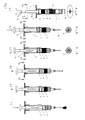
- Fig. 1 the syringe is in the first part of the figure Starting state reproduced in which they on end provided with a closure 14 is.
- the cannula 15 is then already in the sub-figure b put on, the rest of the solvent already in the distal chamber 7 is transferred and the two Plugs 2.6 lie against each other.
- Piston rod 3 prevented from further adjustment because a locking element 13 prevents further advancement.
- the piston rod 3 In the part figure c is the piston rod 3 by 90 ° rotated, whereby the just acting as a stop Locking elements 13 through the edge recess 11 into the interior of the Syringe barrel 1 can enter.
- the syringe is vented; the Partial figure e indicates the condition that after the puncture of the vessel at the time of injection Syringe plunger 2 is pulled back a little to check whether blood appears at the distal end of the syringe. Provided if this is the case, the injection can then be made take place until the syringe barrel 1 according to partial figure f is completely empty.
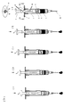
- FIG. 2 is based on the state as it is in FIG. 1b is reproduced and demonstrated in the sub-figures b-e, as by rotating the piston rod 3 several times, here a total of four subsets are injected sequentially can be. After the injection of each subset is one Rotation of the piston rod 3 is required so that each Locking element 13 after it first served as a stop has, then through the edge recess 11 inside of the syringe barrel 1 can occur.
Abstract
Description
Die Erfindung betrifft eine Spritze für medizinische Zwecke mit einem Spritzenzylinder, wenigstens einem darin angeordneten und mittels einer Kolbenstange verstellbaren Stopfen sowie einer endseitig am Spritzenzylinder angeschlossenen Fingerauflage, die mit einer Durchtrittsöffnung für die Kolbenstange versehen ist, insbesondere in Form einer Doppelkammerspritze, bei der der pharmazeutische Wirkstoff und das Lösungsmittel bis zur Applikation mittels eines weiteren Stopfens voneinander getrennt in einer distalen und einer proximalen Kammer angeordnet sind und über einen by-pass zusammengeführt werden können. The invention relates to a syringe for medical Purposes with a syringe barrel, at least one in it arranged and adjustable by means of a piston rod Plug and one end of the syringe barrel connected finger rest with a Passage opening for the piston rod is provided, especially in the form of a double-chamber syringe, in which the active pharmaceutical ingredient and the solvent bis for application with another stopper separated from each other in a distal and a proximal chamber are arranged and by-pass can be merged.
Derartige Spritzen sind in vielfältigen Varianten aus der Praxis bekannt. Dabei ist es insbesondere bei Doppelkammerspritzen entscheidend, den pharmazeutischen Wirkstoff, der in pulverähnlicher Form vorliegt, mit dem Lösungsmittel unmittelbar vor der Anwendung kontaminationsfrei zu vermischen, also zu rekonstituieren, wobei dieser Vorgang möglichst gleichmäßig erfolgen soll, um eine möglichst optimale Rückführung der pharmazeutischen Substanz in den ursprünglichen Zustand zu erreichen. Hierzu wurde auch bereits vorgeschlagen, die Kolbenstange mit einem Gewinde zu versehen, so daß durch die schraubende Bewegung der Kolbenstange ein gleichmäßiger Vortrieb des Kolbens mit reduzierter Geschwindigkeit sichergestellt ist.Such syringes are available in a wide variety of variants Known practice. It is particularly at Double-chamber syringes, the pharmaceutical one Active ingredient that is in powder-like form with the Solvent immediately before use to mix without contamination, i.e. to reconstitute, this process should take place as evenly as possible, in order to optimize the return of the pharmaceutical substance in its original state to reach. For this purpose, the To provide the piston rod with a thread so that the screwing movement of the piston rod smooth propulsion of the piston with reduced Speed is ensured.
Darüber hinaus ist es jedoch oftmals erforderlich, die rekonstituierte Substanz sequentiell, also in mehreren Teilmengen, zu verabreichen, wie dies beispielsweise beim Setzen von Quaddeln in der Neuraltherapie gewünscht ist.In addition, however, it is often required that reconstituted substance sequentially, i.e. in several To administer subsets, such as in Setting wheals in neural therapy is desired.
Der Erfindung liegt die Aufgabe zugrunde, eine Spritze der eingangs genannten Art so auszubilden, daß zum einen ein kontrolliert ablaufender Rekonstitutionsvorgang gewährleistet ist und darüber hinaus eine sequentielle Verabreichung der rekonstituierten Substanz ermöglicht wird.The invention has for its object a syringe type mentioned so that on the one hand controlled reconstitution process is guaranteed and also a sequential Allows administration of the reconstituted substance becomes.
Diese Aufgabe wird nach der Erfindung dadurch gelöst, daß die Kolbenstange mit radial vorstehenden Rastelementen versehen ist, für deren Durchtritt durch die Fingerauflage die Durchtrittsöffnung mit wenigstens einer Randaussparung versehen ist, wobei die Rastelemente in axialer Richtung der Kolbenstange zu mehreren hintereinander und/oder axial aufeinanderfolgend wechselweise um einen bestimmten Drehwinkel um die Längsachse der Kolbenstange versetzt angeordnet sind, und wobei im Bereich der Randaussparung ein elastisch federndes Klemmelement vorgesehen ist, das der Kolbenstange bzw. den Rastelementen anliegt.This object is achieved according to the invention in that the piston rod with radially protruding locking elements is provided for their passage through the finger rest the passage opening with at least one edge recess is provided, the locking elements in the axial direction the piston rod to several in a row and / or axially successively alternately around a certain one Angle of rotation offset about the longitudinal axis of the piston rod are arranged, and being in the region of the edge recess an elastically resilient clamping element is provided, which the piston rod or the locking elements abuts.
Der durch die Erfindung erreichte Vorteil besteht im wesentlichen darin, daß zunächst bei der Rekonstituierung der pharmazeutischen Substanz die in axialer Richtung angeordneten Rastelemente an dem bzw. den elastisch federnden Klemmelementen eine Abbremsung insoweit erfahren, daß die Überleitung des Lösungsmittels in die distale, also die kanülenseitige Kammer gegenüber einer glatten Kolbenstange vergleichsweise langsam erfolgt. Die demgegenüber axial aufeinanderfolgend wechselweise um einen bestimmten Drehwinkel angeordneten Rastelemente ermöglichen das sequentielle Injizieren von Teilmengen der Substanz, wobei das jeweils nachfolgende Rastelement stets einen die weiteren Injektion begrenzenden Anschlag bildet. Eine weitere Injektion ist dann jeweils erst nach entsprechendem Drehen der Kolbenstange möglich.The advantage achieved by the invention is essential in the fact that initially in the reconstitution of the pharmaceutical substance in the axial direction arranged locking elements on the or the elastic resilient clamping elements a braking so far learn that the transfer of the solvent into the distal, i.e. the cannula-side chamber opposite one smooth piston rod is comparatively slow. The in contrast, alternating axially in succession a certain angle of rotation arranged locking elements enable the sequential injection of subsets of the Substance, with the subsequent locking element always forms a stop limiting further injection. A further injection is then only after appropriate rotation of the piston rod possible.
In bevorzugter Ausführungsform der Erfindung sind die Rastelemente zweckmäßigerweise paarweise diametral sich gegenüberstehend angeordnet. Bei den aufeinanderfolgend wechselweise angeordneten Rastelementen empfiehlt es sich, daß der Drehwinkel zwischen aufeinanderfolgenden Rastelementen 90° beträgt.In a preferred embodiment of the invention Locking elements expediently in pairs diametrically arranged opposite. With the successive alternately arranged locking elements, it is recommended that the angle of rotation between successive Locking elements is 90 °.
Um einerseits eine optimale Rekonstituierung des pharmazeutischen Produktes zu erreichen, andererseits zu verhindern, daß hierbei die Kolbenstange etwas zu tief in den Spritzenzylinder eingedrückt wird und hierdurch bereits ein Teil der in der Regel teuren pharmazeutischen Substanz über die Kanüle entweicht, ist im Rahmen der Erfindung vorgesehen, daß die Länge des in ihrer axialen Richtung mit Rastelementen besetzten Teils der Kolbenstange so bemessen ist, daß das Lösungsmittel vollständig in die distale Kammer übergeleitet ist, sobald das letzte der Rastelemente das Klemmelement überwunden hat. Hier schließt sich dann im übrigen in der Regel ein weiteres, bezüglich seines Drehwinkels versetzt angeordnetes Rastelement an, wodurch - vor der sich anschließenden Entlüftung des Spritzenzylinders und der Injektion - zunächst eine weitere Verstellung des Spritzenkolbens verhindert wird.In order on the one hand to optimally reconstitute the pharmaceutical product, on the other hand prevent the piston rod from being too deep the syringe barrel is pushed in and thereby already part of the usually expensive pharmaceutical Substance escaping through the cannula is part of the Invention provided that the length of its axial Direction with locking parts of the Piston rod is dimensioned so that the solvent is completely transferred into the distal chamber as soon as the last of the locking elements overcome the clamping element Has. This usually includes this further, offset with respect to its angle of rotation arranged locking element, whereby - in front of then venting the syringe barrel and the Injection - first another adjustment of the Syringe plunger is prevented.
Für das sequentielle Injizieren des pharmazeutischen Produktes ist es zweckmäßig, wenn der Abstand der unter einem bestimmten Drehwinkel versetzt gegeneinander angeordneten Rastelemente so bemessen ist, daß durch den zwischen zwei Rastelementen möglichen Verstellhub der Kolbenstange eine vorbestimmte Teilmenge injiziert wird. Für die Injizierung unterschiedlicher Teilmengen sind im Rahmen der Erfindung entsprechende Kolbenstangen mit angepaßtem Abstand der Rastelemente vorgesehen. Auf diese Weise läßt sich die für sequentielle Injektionen vorgesehene Teilmenge problemlos durch Verwendung einer bestimmten Kolbenstange vorgeben, wobei die Kolbenstangen in übersichtlicher Weise - beispielsweise durch entsprechende Farbgebung - markiert sein können.For the sequential injection of the pharmaceutical Product it is useful if the distance below the offset from each other by a certain angle of rotation Arranged locking elements is dimensioned so that by the possible adjustment stroke between two locking elements Piston rod is injected a predetermined amount. For the injection of different subsets are in Within the scope of the invention corresponding piston rods adapted distance of the locking elements provided. To this Way for sequential injections intended subset easily using a specify a specific piston rod, the piston rods in a clear manner - for example by appropriate coloring - can be marked.
Die Randaussparung der Durchtrittsöffnung in der Fingerauflage besitzt zweckmäßigerweise eine rechtwinklige Form, wobei durchaus auch andere, beispielsweise sektorförmige Gestaltungen denkbar sind. The edge recess of the passage opening in the Expediently has a right-angled finger rest Form, although quite others, for example sector-shaped designs are conceivable.
Das Klemmelement ist vorteilhafterweise lippenartig ausgebildet und hinter der Randaussparung ins Lumen des Spritzenzylinders weisend angeordnet.The clamping element is advantageously lip-like trained and behind the edge recess in the lumen of the Syringe barrel arranged facing.
Schließlich ist es im Rahmen der Erfindung zweckmäßig, wenn die Rastelemente im Querschnitt quader- oder keilförmige, mit dem Keilwinkel zum Stopfen weisende Gestalt besitzen.Finally, it is expedient within the scope of the invention if the locking elements in cross-section or wedge-shaped, with the wedge angle facing the plug To have shape.
Im folgenden wird die Erfindung an in der Zeichnung dargestellten Ausführungsbeispielen näher erläutert; es zeigen:
- Fig. 1
- in den Teilfiguren a-f die schrittweise Vorbereitung einer Doppelkammerspritze für die Injektion,
- Fig. 2
- in den Teilfiguren a-e die sequentielle Verabreichung von Teilmengen der im Spritzenzylinder vorhandenen pharmazeutischen Substanz.
- Fig. 1
- in the partial figures af the gradual preparation of a double-chamber syringe for the injection,
- Fig. 2
- in the sub-figures ae the sequential administration of subsets of the pharmaceutical substance present in the syringe barrel.
Die in der Zeichnung dargestellte Spritze für medizinische
Zwecke besteht zunächst aus einem Spritzenzylinder 1, in
dem ein üblicher Stopfen 2 angeordnet ist, der über eine
Kolbenstange 3 verstellbar ist. Am einen Ende des
Spritzenzylinders 1 ist eine Fingerauflage 4
angeschlossen, die mit einer Durchtrittsöffnung 5 für die
Kolbenstange 3 versehen ist.The syringe shown in the drawing for medical
Purposes initially consists of a
Im Spritzenzylinder 1 ist ein weiterer Stopfen 6
angeordnet, durch den dieser in zwei voneinander getrennte
Kammern 7,8 unterteilt ist. Der pharmazeutische Wirkstoff
ist dabei in pulverförmiger, in der Regel
gefriergetrocknetem Zustand in der distalen Kammer 7
angeordnet, während die proximale Kammer 8 mit dem
zugehörigen Lösungsmittel gefüllt ist. Das Lösungsmittel
kann durch Ausüben von Druck auf die Kolbenstange 3 über
einen by-pass 9 in die kanülenseitige, den
pharmazeutischen Wirkstoff enthaltende Kammer 7 überführt
werden, wobei sich der die beiden Kammern 6,7 voneinander
trennende Mittelstopfen 6 in den Bereich des by-passes 9
verlagert.A
Um ein zu schnelles Überströmen des Lösungsmittels in die
distale Kammer 7 zu verhindern, ist die Kolbenstange 3 mit
radial vorstehenden Rastelementen 10 versehen, für deren
Durchtritt durch die Fingerauflage 4 Randaussparungen 11
in der Durchtrittsöffnung 5 vorgesehen sind. Die
Rastelemente 10 sind in axialer Richtung der
Kolbenstange 3 zu mehreren hintereinander angeordnet,
wobei im Bereich der Randaussparung 11 ein elastisch
federndes Klemmelement 12 vorgesehen ist. Dieses
Klemmelement 12 liegt der Kolbenstange 3 bzw. den
Rastelementen 10 an und bremst den Vorschub der
Kolbenstange 3, so daß eine langsame Durchmischung des
Lösungsmittels mit der pharmazeutischen Substanz
gewährleistet wird.To overflow the solvent too quickly into the
To prevent
Zusätzlich sind, wie sich insbesondere aus der Fig. 2
ergibt, weitere Rastelemente 13 vorgesehen, die axial
aufeinanderfolgend wechselweise um einen bestimmten
Drehwinkel um die Längsachse der Kolbenstange 3 versetzt
angeordnet sind. Diese Rastelemente 13 bilden jeweils
einen Anschlag an der Fingerauflage 4 und dienen dazu,
Teilmengen der im Spritzenzylinder 1 enthaltenen Substanz
sequentiell zu injizieren. Jedesmal, wenn eines der
Rastelemente 13 an der Fingerauflage 4 anschlägt, muß die
Kolbenstange 3 um einen durch die Anordnung der
Rastelemente 13 vorgegebenen Drehwinkel gedreht werden, so
daß dann das eben noch als Anschlag dienende
Rastelement 13 durch die Randaussparung 11 durchtreten
kann und somit die Injektion einer weiteren Teilmenge
ermöglicht, bis das nächstfolgende Rastelement 13 erneut
an der Fingerauflage 4 anschlägt.In addition, as can be seen in particular from FIG. 2
results,
Die Rastelemente 10,13 sind, wie sich aus der Zeichnung
ersehen läßt, paarweise diametral sich gegenüberstehend
angeordnet. Weiter beträgt der Drehwinkel - wie ebenfalls
aus der Zeichnung folgt - zwischen aufeinanderfolgenden
Rastelementen 13 jeweils 90°.The
Die Länge des Teils der Kolbenstange 3, die in axialer
Richtung mit Rastelementen 10 besetzt ist, ist so
bemessen, daß das Lösungsmittel vollständig in die distale
Kammer 7 übergeleitet ist, sobald das letzte der
Rastelemente 10 das Klemmelement 12 überwunden hat. Damit
erfolgt eine Bremsung der Kolbenstange 3 während der
gesamten Zeit des Überfüllens des Lösungsmittels in die
distale Kammer 7 und endet - zweckmäßigerweise durch
Anschlag eines demgegenüber gedrehten Rastelementes 13 -
genau in dem Augenblick, zu dem sich die beiden
Stopfen 2,6 einander anlegen.The length of the part of the
Um jeweils vorgegebene Teilmengen der pharmazeutischen
Substanz in genau der vorgeschriebenen Dosierung
applizieren zu können, ist der Abstand der unter einem
bestimmten Drehwinkel versetzt gegeneinander angeordneten
Rastelemente 13 so bemessen, daß der sich durch den
Abstand zweier benachbarter Rastelemente 13 ergebende
Verstellhub der Kolbenstange 3 genau zur Injizierung der
gewünschten Teilmenge führt.At predetermined subsets of pharmaceutical
Substance in exactly the prescribed dosage
to be able to apply is the distance between the one
certain angle of rotation offset from each
Um hierbei auch unterschiedliche Teilmengen injizieren zu
können, ist es ausreichend, entsprechend unterschiedliche
Kolbenstangen 3 mit angepaßtem Abstand der Rastelemente 13
vorzusehen. Diese Kolbenstangen 3 können zum einen
entsprechende Markierungen beispielsweise in Form von
Farben besitzen, um möglichst Verwechslungen
auszuschließen und dabei entweder einzeln oder als Auswahl
der Spritze beigegeben sein.To also inject different subsets
, it is sufficient to have different ones
Piston
Die Randaussparung 11 der Durchschnittsöffnung 5 weist in der Regel rechteckige Form auf, kann jedoch auch bogen-bzw. sektorförmig gestaltet sein.The edge recess 11 of the average opening 5 points in generally rectangular shape, but can also be arched or be sector-shaped.
Das Klemmelement 12 ist lippenartig ausgebildet und hinter
der Randaussparung 11 in das Lumen des Spritzenzylinders 1
weisend angeordnet.The
Wie sich weiter aus der Zeichnung ergibt, besitzen die
Rastelemente 10,13 im Querschnitt quader- oder keilförmige
Gestalt, wobei im letzteren Fall der Keilwinkel zum
Stopfen 2 hin weist.As can be seen from the drawing, they have
In Fig. 1 ist in der Teilfigur a zunächst die Spritze im
Ausgangszustand wiedergegeben, in welchem sie am
kanülenseitigen Ende noch mit einem Verschluß 14 versehen
ist. In der Teilfigur b ist dann bereits die Kanüle 15
aufgesetzt, wobei im übrigen das Lösungsmittel bereits in
die distale Kammer 7 übergeführt ist und die beiden
Stopfen 2,6 einander anliegen. In dieser Stellung ist die
Kolbenstange 3 an einer weiteren Verstellung gehindert, da
ein Rastelement 13 das weitere Vorschieben verhindert. In
der Teilfigur c ist die Kolbenstange 3 inzwischen um 90°
gedreht, wodurch die eben noch als Anschlag wirkenden
Rastelemente 13 durch die Randaussparung 11 ins Innere des
Spritzenzylinders 1 eintreten können.In Fig. 1, the syringe is in the first part of the figure
Starting state reproduced in which they on
end provided with a
In der Teilfigur d erfolgt die Entlüftung der Spritze; die
Teilfigur e deutet den Zustand an, daß nach der Punktion
des Gefäßes bei der Injektion zunächst der
Spritzenkolben 2 etwas zurückgezogen wird, um zu prüfen,
ob Blut am distalen Ende der Spritze erscheint. Sofern
dies der Fall ist, kann anschließend die Injektion
erfolgen, bis der Spritzenzylinder 1 gemäß Teilfigur f
vollständig entleert ist.In sub-figure d, the syringe is vented; the
Partial figure e indicates the condition that after the puncture
of the vessel at the time of
Die Fig. 2 geht aus von dem Zustand, wie er in der Fig. lb
wiedergegeben ist und demonstriert in den Teilfiguren b-e,
wie durch jeweiliges Drehen der Kolbenstange 3 mehrere,
hier insgesamt vier Teilmengen sequentiell injiziert
werden können. Nach der Injektion jeder Teilmenge ist eine
Drehung der Kolbenstange 3 erforderlich, so daß jedes
Rastelement 13, nachdem es zunächst als Anschlag gedient
hat, anschließend durch die Randaussparung 11 ins Innere
des Spritzenzylinders 1 eintreten kann.FIG. 2 is based on the state as it is in FIG. 1b
is reproduced and demonstrated in the sub-figures b-e,
as by rotating the
Claims (10)
Applications Claiming Priority (2)
| Application Number | Priority Date | Filing Date | Title |
|---|---|---|---|
| DE19912322A DE19912322A1 (en) | 1999-03-19 | 1999-03-19 | Syringe for medical purposes |
| DE19912322 | 1999-03-19 |
Publications (2)
| Publication Number | Publication Date |
|---|---|
| EP1038543A1 true EP1038543A1 (en) | 2000-09-27 |
| EP1038543B1 EP1038543B1 (en) | 2002-03-27 |
Family
ID=7901587
Family Applications (1)
| Application Number | Title | Priority Date | Filing Date |
|---|---|---|---|
| EP99122359A Expired - Lifetime EP1038543B1 (en) | 1999-03-19 | 1999-11-10 | Syringe for medical purposes |
Country Status (9)
| Country | Link |
|---|---|
| US (1) | US6419656B1 (en) |
| EP (1) | EP1038543B1 (en) |
| JP (1) | JP3458188B2 (en) |
| AT (1) | ATE214955T1 (en) |
| CA (1) | CA2300844C (en) |
| DE (2) | DE19912322A1 (en) |
| DK (1) | DK1038543T3 (en) |
| ES (1) | ES2171318T3 (en) |
| PT (1) | PT1038543E (en) |
Cited By (6)
| Publication number | Priority date | Publication date | Assignee | Title |
|---|---|---|---|---|
| US6520935B1 (en) | 1994-12-12 | 2003-02-18 | Becton, Dickinson And Company | Syringe and tip cap assembly |
| WO2004011064A1 (en) | 2002-07-25 | 2004-02-05 | Cambridge Consultants Limited | Syringes |
| WO2007132191A1 (en) * | 2006-05-11 | 2007-11-22 | Owen Mumford Limited | Injection device |
| US8002734B2 (en) | 2005-08-13 | 2011-08-23 | Boehringer Ingelheim International Gmbh | Dual chamber container and process for its filling up |
| US8096971B2 (en) | 2005-08-13 | 2012-01-17 | Boehringer Ingelheim International Gmbh | Dual chamber container for lyophilization, process for the filling up and use thereof |
| WO2016084004A1 (en) * | 2014-11-26 | 2016-06-02 | Fisher Clinical Services GmbH | Syringe assembly with plunger rod backstop and method of use |
Families Citing this family (86)
| Publication number | Priority date | Publication date | Assignee | Title |
|---|---|---|---|---|
| DE10036594A1 (en) * | 2000-07-27 | 2002-02-07 | Pfeiffer Erich Gmbh & Co Kg | Delivery unit, especially for pharmaceuticals, comprises a container composed of separate chambers which hold a media component, an actuating unit and a connection between the chambers |
| DE10140704A1 (en) * | 2001-08-18 | 2003-03-06 | Vetter & Co Apotheker | Process for mixing a poorly soluble pharmaceutical substance with a solvent and syringe to apply the process |
| JP4838955B2 (en) † | 2001-08-21 | 2011-12-14 | 武田薬品工業株式会社 | Two-chamber prefilled syringe |
| US6972006B2 (en) * | 2002-09-18 | 2005-12-06 | G6 Science Corp. | Syringe device with resistive ridges and methods of use |
| DE10340586A1 (en) * | 2003-09-03 | 2005-04-07 | Tecpharma Licensing Ag | Mixing device for multi-chamber ampoule |
| CA2549297C (en) * | 2003-12-16 | 2012-11-27 | Idexx Laboratories, Inc. | Tissue sampling device and method |
| US7998106B2 (en) | 2004-05-03 | 2011-08-16 | Thorne Jr Gale H | Safety dispensing system for hazardous substances |
| US7101354B2 (en) | 2004-05-03 | 2006-09-05 | Infusive Technologies, Llc | Mixing syringe with and without flush |
| US20080132852A1 (en) * | 2004-07-28 | 2008-06-05 | Kleyhan Gennady I | Dosage device |
| DE102004056617A1 (en) * | 2004-11-24 | 2006-06-01 | Arthur Fabian | Medical double-chamber syringe made of plastic |
| US20060157507A1 (en) * | 2004-12-30 | 2006-07-20 | Chang Byeong S | Multi-functional container closure delivery system |
| US20060144869A1 (en) * | 2004-12-30 | 2006-07-06 | Chang Byeong S | Container closure delivery system |
| US7959600B2 (en) * | 2004-12-30 | 2011-06-14 | Byeong S. Chang | Container closure delivery system |
| US8425453B2 (en) | 2004-12-30 | 2013-04-23 | Integrity Bio, Inc. | Compact medication reconstitution device and method |
| ES2396745T3 (en) | 2005-02-01 | 2013-02-25 | Intelliject, Inc. | Devices for medication administration |
| CN101175519A (en) * | 2005-05-16 | 2008-05-07 | 马林克罗特公司 | Multi-stage syringe and methods of using the same |
| US7780695B2 (en) * | 2005-06-30 | 2010-08-24 | Codman & Shurtleff, Inc. | Chemically based vascular occlusion device deployment |
| DE102005038497A1 (en) * | 2005-08-13 | 2007-02-15 | Boehringer Ingelheim Pharma Gmbh & Co. Kg | Double chamber container without bypass |
| DE102005038458A1 (en) * | 2005-08-13 | 2007-02-15 | Boehringer Ingelheim Pharma Gmbh & Co. Kg | Double-chamber container without bypass in the cylindrical body |
| US20070060887A1 (en) * | 2005-08-22 | 2007-03-15 | Marsh David A | Ophthalmic injector |
| JP4150389B2 (en) * | 2005-09-05 | 2008-09-17 | 日本ケミカルリサーチ株式会社 | Injection device |
| JP4834389B2 (en) * | 2005-11-29 | 2011-12-14 | 前田産業株式会社 | Injection device |
| US20070185438A1 (en) * | 2006-02-09 | 2007-08-09 | Shlomo Haimi | Multi-chamber mixing ampoule |
| US7862540B2 (en) * | 2006-05-17 | 2011-01-04 | Alcon Research, Ltd. | Ophthalmic injection device using shape memory alloy |
| US20070268340A1 (en) * | 2006-05-17 | 2007-11-22 | Bruno Dacquay | Ophthalmic Injection System and Method Using Piezoelectric Array |
| US7887521B2 (en) * | 2006-05-17 | 2011-02-15 | Alcon Research, Ltd. | Ophthalmic injection system |
| US20070270744A1 (en) * | 2006-05-17 | 2007-11-22 | Bruno Dacquay | Limited Reuse Assembly For Ophthalmic Injection Device |
| US20070270768A1 (en) * | 2006-05-17 | 2007-11-22 | Bruno Dacquay | Mechanical Linkage Mechanism For Ophthalmic Injection Device |
| US7674243B2 (en) * | 2006-05-17 | 2010-03-09 | Alcon Inc. | Ophthalmic injection device using piezoelectric array |
| US7811252B2 (en) * | 2006-05-17 | 2010-10-12 | Alcon Research, Ltd. | Dosage control device |
| US20070270750A1 (en) * | 2006-05-17 | 2007-11-22 | Alcon, Inc. | Drug delivery device |
| DE102006038123C5 (en) * | 2006-08-14 | 2012-05-03 | Tecpharma Licensing Ag | Injection device with mechanical lock |
| FR2905682B1 (en) * | 2006-09-13 | 2011-05-20 | Becton Dickinson France | CONTAINER, MEDICAL DEVICE AND METHOD FOR CONTAINING AND EXPULTING A PRODUCT. |
| US20080097379A1 (en) * | 2006-09-26 | 2008-04-24 | Alcon Manufacturing, Ltd. | Ophthalmic injection method |
| US20080125712A1 (en) * | 2006-09-26 | 2008-05-29 | Alcon Manufacturing, Ltd. | Ophthalmic injection system |
| US20080097390A1 (en) * | 2006-09-27 | 2008-04-24 | Alcon Manufacturing, Ltd. | Spring actuated delivery system |
| EP2063829B1 (en) * | 2006-10-16 | 2010-12-08 | Alcon Research, Ltd. | Universal rechargeable limited reuse assembly for ophthalmic hand piece |
| US20080281292A1 (en) * | 2006-10-16 | 2008-11-13 | Hickingbotham Dyson W | Retractable Injection Port |
| CN102014987A (en) * | 2006-10-16 | 2011-04-13 | 爱尔康研究有限公司 | Method of operating ophthalmic hand piece with disposable end |
| US9022970B2 (en) * | 2006-10-16 | 2015-05-05 | Alcon Research, Ltd. | Ophthalmic injection device including dosage control device |
| SE530568C2 (en) | 2006-11-13 | 2008-07-08 | Medtentia Ab | Medical device for improving function of heart valve, has flange unit connected to loop-shaped support and provided to be arranged against annulus when loop shaped support abut heart valve |
| CA2574746A1 (en) * | 2007-01-22 | 2008-07-22 | Duoject Medical Systems Inc. | Syringe having venting structure and method for mixing two substances in a syringe |
| US20080275387A1 (en) * | 2007-05-03 | 2008-11-06 | Yeadon Stephen C | Hemostatic medical device |
| US20090018548A1 (en) * | 2007-07-13 | 2009-01-15 | Charles Steven T | Pneumatically-Powered Intraocular Lens Injection Device with Removable Cartridge |
| US20090018512A1 (en) * | 2007-07-13 | 2009-01-15 | Charles Steven T | Pneumatically-Powered Ophthalmic Injector |
| US7740619B2 (en) * | 2007-08-01 | 2010-06-22 | Alcon Research, Ltd. | Spring driven ophthalmic injection device with safety actuator lockout feature |
| US7629768B2 (en) * | 2007-08-03 | 2009-12-08 | Alcon Research, Ltd. | Easy cleaning C-shaped charging base |
| US20090036842A1 (en) * | 2007-08-03 | 2009-02-05 | Raffi Pinedjian | Consumable Activation Lever For Injection Device |
| WO2009019673A2 (en) * | 2007-08-07 | 2009-02-12 | Shlomo Haimi | Multi-chamber mixing ampoule |
| KR101439466B1 (en) * | 2007-11-08 | 2014-09-15 | 주식회사 엘지생명과학 | Device and kit for drug injection |
| DK2280751T3 (en) | 2008-05-14 | 2022-02-28 | Biolyph Llc | REAGENT MIXTURE AND DELIVERY DEVICES AND METHODS THEREOF |
| EP2193817A1 (en) * | 2008-12-02 | 2010-06-09 | Sanofi-Aventis Deutschland GmbH | Drive assembly suitable for use in a medication delivery device and medication delivery device |
| US8632511B2 (en) | 2009-05-06 | 2014-01-21 | Alcon Research, Ltd. | Multiple thermal sensors in a multiple processor environment for temperature control in a drug delivery device |
| IN2012DN00344A (en) | 2009-07-10 | 2015-05-08 | Becton Dickinson Co | |
| JP5385074B2 (en) * | 2009-09-29 | 2014-01-08 | テルモ株式会社 | Drug infusion tool |
| US8177747B2 (en) | 2009-12-22 | 2012-05-15 | Alcon Research, Ltd. | Method and apparatus for drug delivery |
| US20120316509A1 (en) * | 2010-02-12 | 2012-12-13 | Medmix Systems Ag | Discharge device having a locking element |
| EP2588404B1 (en) | 2010-06-29 | 2018-03-28 | Biolyph, Llc | Reagent preparation assembly |
| JP4757951B1 (en) * | 2010-10-19 | 2011-08-24 | 株式会社アルテ | Two-chamber syringe |
| US8919390B2 (en) | 2010-11-18 | 2014-12-30 | Biolyph, L.L.C. | Reagent preparation and dispensing device |
| WO2012089445A1 (en) | 2010-12-06 | 2012-07-05 | Novo Nordisk Health Care Ag | Wheel operated drug delivery device |
| US9084849B2 (en) | 2011-01-26 | 2015-07-21 | Kaleo, Inc. | Medicament delivery devices for administration of a medicament within a prefilled syringe |
| WO2012110057A1 (en) | 2011-02-15 | 2012-08-23 | Chemisches Institut Schaefer Ag | Cefuroxime safety kit |
| US10092688B2 (en) | 2011-05-13 | 2018-10-09 | Laura Jean Robinson | Medicament kit and method of use |
| AR088689A1 (en) * | 2011-11-09 | 2014-06-25 | Sanofi Aventis Deutschland | DRIVE ASSEMBLY FOR A MEDICATION ADMINISTRATION DEVICE AND A MEDICATION ADMINISTRATION DEVICE THAT INCLUDES A DRIVE ASSEMBLY |
| US9751056B2 (en) | 2012-01-23 | 2017-09-05 | Merit Medical Systems, Inc. | Mixing syringe |
| US8834449B2 (en) | 2012-01-23 | 2014-09-16 | Ikomed Technologies, Inc. | Mixing syringe |
| WO2013161434A1 (en) * | 2012-04-24 | 2013-10-31 | テルモ株式会社 | Syringe and mounting fixture |
| US9522235B2 (en) | 2012-05-22 | 2016-12-20 | Kaleo, Inc. | Devices and methods for delivering medicaments from a multi-chamber container |
| US9731076B2 (en) | 2012-06-29 | 2017-08-15 | Ethicon, Inc. | Multi-compartment pre-filled mixing syringes with bypass |
| PL2981316T3 (en) * | 2013-04-03 | 2022-10-03 | Sean Terrence ARMSTRONG | Syringe and an accessory therefor |
| WO2014162551A1 (en) * | 2013-04-04 | 2014-10-09 | テルモ株式会社 | Syringe |
| US9308508B2 (en) | 2013-07-22 | 2016-04-12 | Kianoosh Peyvan | Sequential delivery device and method |
| EP3065801B1 (en) | 2013-11-05 | 2019-08-14 | 3P Innovation Limited | A pharmaceutical component-mixing delivery assembly |
| JP6490790B2 (en) | 2014-07-24 | 2019-03-27 | テレフレックス メディカル インコーポレイテッド | Syringe with dose divider |
| US10201692B2 (en) | 2014-09-09 | 2019-02-12 | Byeong Seon Chang | Solution delivery device and method |
| EP3028946A1 (en) | 2014-12-05 | 2016-06-08 | F. Hoffmann-La Roche AG | Preparing a double chamber container |
| US10695495B2 (en) | 2015-03-24 | 2020-06-30 | Kaleo, Inc. | Devices and methods for delivering a lyophilized medicament |
| WO2017004345A1 (en) | 2015-06-30 | 2017-01-05 | Kaleo, Inc. | Auto-injectors for administration of a medicament within a prefilled syringe |
| US10182939B2 (en) | 2015-09-16 | 2019-01-22 | Novartis Ag | Hydraulic injector and methods for intra-ocular lens insertion |
| CH711657A2 (en) * | 2015-10-19 | 2017-04-28 | Tecpharma Licensing Ag | Device for administering an active substance and method for operating this device. |
| CH711656A2 (en) * | 2015-10-19 | 2017-04-28 | Tecpharma Licensing Ag | Device for administering an active substance and method for operating this device. |
| CN117065151A (en) * | 2017-12-13 | 2023-11-17 | 里珍纳龙药品有限公司 | Device and method for accurate dose delivery |
| US11083847B2 (en) | 2018-01-26 | 2021-08-10 | Becton, Dickinson And Company | Flush syringe with flip cap |
| US11419991B2 (en) | 2018-11-13 | 2022-08-23 | Credence Medsystems, Inc. | System and method for microdose injection |
| EP4009936A4 (en) | 2019-08-09 | 2023-08-09 | Kaleo, Inc. | Devices and methods for delivery of substances within a prefilled syringe |
Citations (4)
| Publication number | Priority date | Publication date | Assignee | Title |
|---|---|---|---|---|
| CH268694A (en) * | 1950-04-17 | 1950-05-31 | Ag Mediglass | Injection syringe and method for making the same. |
| FR1412547A (en) * | 1964-08-20 | 1965-10-01 | Comptoir De Diffusion De Produ | Injection syringe |
| FR2024089A5 (en) * | 1968-05-20 | 1970-08-21 | Tasman Vaccine Labo | |
| US5080649A (en) * | 1990-02-07 | 1992-01-14 | Arzneimittel Gmbh Apotheker Vetter & Co. Ravensburg | Dual-compartment hypodermic syringe |
Family Cites Families (3)
| Publication number | Priority date | Publication date | Assignee | Title |
|---|---|---|---|---|
| DE2810370A1 (en) * | 1978-03-10 | 1979-09-20 | Wolfram Dr Med Breunig | Medical and chemical syringe - has locking devices in cylinder securing piston in different positions |
| IL105396A (en) * | 1992-04-30 | 1998-02-22 | Takeda Chemical Industries Ltd | Prefilled syringe |
| US5380295A (en) * | 1992-12-14 | 1995-01-10 | Mallinckrodt Medical, Inc. | Delivery apparatus with mechanism preventing rearward movement of a piston disposed therein |
-
1999
- 1999-03-19 DE DE19912322A patent/DE19912322A1/en not_active Ceased
- 1999-11-10 PT PT99122359T patent/PT1038543E/en unknown
- 1999-11-10 AT AT99122359T patent/ATE214955T1/en active
- 1999-11-10 EP EP99122359A patent/EP1038543B1/en not_active Expired - Lifetime
- 1999-11-10 DK DK99122359T patent/DK1038543T3/en active
- 1999-11-10 ES ES99122359T patent/ES2171318T3/en not_active Expired - Lifetime
- 1999-11-10 DE DE59901059T patent/DE59901059D1/en not_active Expired - Lifetime
-
2000
- 2000-03-13 JP JP2000068793A patent/JP3458188B2/en not_active Expired - Lifetime
- 2000-03-17 CA CA002300844A patent/CA2300844C/en not_active Expired - Lifetime
- 2000-03-20 US US09/528,513 patent/US6419656B1/en not_active Expired - Lifetime
Patent Citations (4)
| Publication number | Priority date | Publication date | Assignee | Title |
|---|---|---|---|---|
| CH268694A (en) * | 1950-04-17 | 1950-05-31 | Ag Mediglass | Injection syringe and method for making the same. |
| FR1412547A (en) * | 1964-08-20 | 1965-10-01 | Comptoir De Diffusion De Produ | Injection syringe |
| FR2024089A5 (en) * | 1968-05-20 | 1970-08-21 | Tasman Vaccine Labo | |
| US5080649A (en) * | 1990-02-07 | 1992-01-14 | Arzneimittel Gmbh Apotheker Vetter & Co. Ravensburg | Dual-compartment hypodermic syringe |
Cited By (9)
| Publication number | Priority date | Publication date | Assignee | Title |
|---|---|---|---|---|
| US6520935B1 (en) | 1994-12-12 | 2003-02-18 | Becton, Dickinson And Company | Syringe and tip cap assembly |
| WO2004011064A1 (en) | 2002-07-25 | 2004-02-05 | Cambridge Consultants Limited | Syringes |
| US8002734B2 (en) | 2005-08-13 | 2011-08-23 | Boehringer Ingelheim International Gmbh | Dual chamber container and process for its filling up |
| US8096971B2 (en) | 2005-08-13 | 2012-01-17 | Boehringer Ingelheim International Gmbh | Dual chamber container for lyophilization, process for the filling up and use thereof |
| WO2007132191A1 (en) * | 2006-05-11 | 2007-11-22 | Owen Mumford Limited | Injection device |
| CN101479003B (en) * | 2006-05-11 | 2012-02-22 | 欧文蒙福德有限公司 | Injection device |
| US8167834B2 (en) | 2006-05-11 | 2012-05-01 | Owen Mumford Limited | Injection device |
| US8486007B2 (en) | 2006-05-11 | 2013-07-16 | Owen Mumford Limited | Injection device |
| WO2016084004A1 (en) * | 2014-11-26 | 2016-06-02 | Fisher Clinical Services GmbH | Syringe assembly with plunger rod backstop and method of use |
Also Published As
| Publication number | Publication date |
|---|---|
| US6419656B1 (en) | 2002-07-16 |
| ES2171318T3 (en) | 2002-09-01 |
| DK1038543T3 (en) | 2002-07-08 |
| JP3458188B2 (en) | 2003-10-20 |
| DE59901059D1 (en) | 2002-05-02 |
| CA2300844A1 (en) | 2000-09-19 |
| CA2300844C (en) | 2006-09-19 |
| DE19912322A1 (en) | 2000-09-28 |
| PT1038543E (en) | 2002-07-31 |
| JP2000271218A (en) | 2000-10-03 |
| ATE214955T1 (en) | 2002-04-15 |
| EP1038543B1 (en) | 2002-03-27 |
Similar Documents
| Publication | Publication Date | Title |
|---|---|---|
| EP1038543B1 (en) | Syringe for medical purposes | |
| DE69725220T2 (en) | Piston device with bypass for use in the cylinder of a multi-chamber syringe | |
| EP1287841B1 (en) | Method for mixing a poorly soluble pharmaceutical substance with a solvent and syringe for use with said method | |
| EP1742688B1 (en) | Injection device comprising a dosing unit with multiple anti-twist protection | |
| EP0328699B1 (en) | Syringe for medical use | |
| EP1416983B1 (en) | Connection of housing sections of an administration device for dosed administration of a distributable product | |
| DE69724349T2 (en) | Syringe plunger | |
| DE69921709T2 (en) | Sift-shaped medicament syringe with commissioning mechanism | |
| EP0525525B1 (en) | Injector | |
| EP1414505B1 (en) | Administration appliance comprising a dosage device | |
| DE60308042T2 (en) | PEN DRY MEDICATION SYRINGE | |
| EP1228777B1 (en) | Injection device | |
| DE102004042581B4 (en) | Auto-Pen for dual-chamber ampoule | |
| EP2134392B1 (en) | Method for administering a fluid active substance from a multi-chamber carpule | |
| EP2445552B1 (en) | Administering device having a priming function | |
| DE69726531T2 (en) | Lockable protective sleeve for pre-filled syringe | |
| DE60129431T2 (en) | MEDICAL DEVICE | |
| DE2909002B2 (en) | Single use syringe | |
| DE2648795A1 (en) | PRE-FILLED, EASILY READY TO USE INJECTION SYRINGE | |
| DE102005038458A1 (en) | Double-chamber container without bypass in the cylindrical body | |
| WO2007020239A1 (en) | Twin-chamber receptacle and method for filling the same | |
| DE102005038497A1 (en) | Double chamber container without bypass | |
| DE2701903A1 (en) | ADDED DRUG SYSTEM | |
| DE2259825A1 (en) | INJECTION SYRINGE | |
| EP1523356A1 (en) | Administration device comprising a plunger rod with a return lock |
Legal Events
| Date | Code | Title | Description |
|---|---|---|---|
| PUAI | Public reference made under article 153(3) epc to a published international application that has entered the european phase |
Free format text: ORIGINAL CODE: 0009012 |
|
| 17P | Request for examination filed |
Effective date: 20000719 |
|
| AK | Designated contracting states |
Kind code of ref document: A1 Designated state(s): AT BE CH CY DE DK ES FI FR GB GR IE IT LI LU MC NL PT SE |
|
| AX | Request for extension of the european patent |
Free format text: AL;LT;LV;MK;RO;SI |
|
| AKX | Designation fees paid |
Free format text: AT BE CH CY DE DK ES FI FR GB GR IE IT LI LU MC NL PT SE |
|
| GRAG | Despatch of communication of intention to grant |
Free format text: ORIGINAL CODE: EPIDOS AGRA |
|
| GRAG | Despatch of communication of intention to grant |
Free format text: ORIGINAL CODE: EPIDOS AGRA |
|
| GRAH | Despatch of communication of intention to grant a patent |
Free format text: ORIGINAL CODE: EPIDOS IGRA |
|
| 17Q | First examination report despatched |
Effective date: 20011001 |
|
| REG | Reference to a national code |
Ref country code: GB Ref legal event code: IF02 |
|
| GRAH | Despatch of communication of intention to grant a patent |
Free format text: ORIGINAL CODE: EPIDOS IGRA |
|
| GRAA | (expected) grant |
Free format text: ORIGINAL CODE: 0009210 |
|
| AK | Designated contracting states |
Kind code of ref document: B1 Designated state(s): AT BE CH CY DE DK ES FI FR GB GR IE IT LI LU MC NL PT SE |
|
| PG25 | Lapsed in a contracting state [announced via postgrant information from national office to epo] |
Ref country code: FI Free format text: LAPSE BECAUSE OF FAILURE TO SUBMIT A TRANSLATION OF THE DESCRIPTION OR TO PAY THE FEE WITHIN THE PRESCRIBED TIME-LIMIT Effective date: 20020327 |
|
| REF | Corresponds to: |
Ref document number: 214955 Country of ref document: AT Date of ref document: 20020415 Kind code of ref document: T |
|
| REG | Reference to a national code |
Ref country code: CH Ref legal event code: EP |
|
| REG | Reference to a national code |
Ref country code: CH Ref legal event code: NV Representative=s name: ISLER & PEDRAZZINI AG |
|
| GBT | Gb: translation of ep patent filed (gb section 77(6)(a)/1977) |
Effective date: 20020328 |
|
| REF | Corresponds to: |
Ref document number: 59901059 Country of ref document: DE Date of ref document: 20020502 |
|
| REG | Reference to a national code |
Ref country code: IE Ref legal event code: FG4D Free format text: GERMAN |
|
| REG | Reference to a national code |
Ref country code: DK Ref legal event code: T3 |
|
| REG | Reference to a national code |
Ref country code: PT Ref legal event code: SC4A Free format text: AVAILABILITY OF NATIONAL TRANSLATION Effective date: 20020510 |
|
| ET | Fr: translation filed | ||
| REG | Reference to a national code |
Ref country code: ES Ref legal event code: FG2A Ref document number: 2171318 Country of ref document: ES Kind code of ref document: T3 |
|
| REG | Reference to a national code |
Ref country code: GR Ref legal event code: EP Ref document number: 20020401801 Country of ref document: GR |
|
| PG25 | Lapsed in a contracting state [announced via postgrant information from national office to epo] |
Ref country code: LU Free format text: LAPSE BECAUSE OF NON-PAYMENT OF DUE FEES Effective date: 20021110 |
|
| PG25 | Lapsed in a contracting state [announced via postgrant information from national office to epo] |
Ref country code: CY Free format text: LAPSE BECAUSE OF FAILURE TO SUBMIT A TRANSLATION OF THE DESCRIPTION OR TO PAY THE FEE WITHIN THE PRESCRIBED TIME-LIMIT Effective date: 20021130 |
|
| PLBE | No opposition filed within time limit |
Free format text: ORIGINAL CODE: 0009261 |
|
| STAA | Information on the status of an ep patent application or granted ep patent |
Free format text: STATUS: NO OPPOSITION FILED WITHIN TIME LIMIT |
|
| 26N | No opposition filed |
Effective date: 20021230 |
|
| PG25 | Lapsed in a contracting state [announced via postgrant information from national office to epo] |
Ref country code: MC Free format text: LAPSE BECAUSE OF NON-PAYMENT OF DUE FEES Effective date: 20030601 |
|
| REG | Reference to a national code |
Ref country code: CH Ref legal event code: PCAR Free format text: ISLER & PEDRAZZINI AG;POSTFACH 1772;8027 ZUERICH (CH) |
|
| PGFP | Annual fee paid to national office [announced via postgrant information from national office to epo] |
Ref country code: DK Payment date: 20101108 Year of fee payment: 12 |
|
| REG | Reference to a national code |
Ref country code: DK Ref legal event code: EBP |
|
| PG25 | Lapsed in a contracting state [announced via postgrant information from national office to epo] |
Ref country code: DK Free format text: LAPSE BECAUSE OF NON-PAYMENT OF DUE FEES Effective date: 20111130 |
|
| REG | Reference to a national code |
Ref country code: FR Ref legal event code: PLFP Year of fee payment: 17 |
|
| REG | Reference to a national code |
Ref country code: FR Ref legal event code: PLFP Year of fee payment: 18 |
|
| REG | Reference to a national code |
Ref country code: FR Ref legal event code: PLFP Year of fee payment: 19 |
|
| PGFP | Annual fee paid to national office [announced via postgrant information from national office to epo] |
Ref country code: NL Payment date: 20181126 Year of fee payment: 20 |
|
| PGFP | Annual fee paid to national office [announced via postgrant information from national office to epo] |
Ref country code: SE Payment date: 20181126 Year of fee payment: 20 Ref country code: AT Payment date: 20181127 Year of fee payment: 20 Ref country code: GR Payment date: 20181128 Year of fee payment: 20 Ref country code: PT Payment date: 20181030 Year of fee payment: 20 Ref country code: IE Payment date: 20181123 Year of fee payment: 20 |
|
| PGFP | Annual fee paid to national office [announced via postgrant information from national office to epo] |
Ref country code: GB Payment date: 20181130 Year of fee payment: 20 Ref country code: CH Payment date: 20181129 Year of fee payment: 20 Ref country code: ES Payment date: 20181218 Year of fee payment: 20 Ref country code: FR Payment date: 20181129 Year of fee payment: 20 Ref country code: IT Payment date: 20181126 Year of fee payment: 20 Ref country code: BE Payment date: 20181121 Year of fee payment: 20 |
|
| PGFP | Annual fee paid to national office [announced via postgrant information from national office to epo] |
Ref country code: DE Payment date: 20190131 Year of fee payment: 20 |
|
| REG | Reference to a national code |
Ref country code: DE Ref legal event code: R071 Ref document number: 59901059 Country of ref document: DE |
|
| REG | Reference to a national code |
Ref country code: NL Ref legal event code: MK Effective date: 20191109 |
|
| REG | Reference to a national code |
Ref country code: CH Ref legal event code: PL |
|
| REG | Reference to a national code |
Ref country code: GB Ref legal event code: PE20 Expiry date: 20191109 |
|
| REG | Reference to a national code |
Ref country code: BE Ref legal event code: MK Effective date: 20191110 |
|
| REG | Reference to a national code |
Ref country code: AT Ref legal event code: MK07 Ref document number: 214955 Country of ref document: AT Kind code of ref document: T Effective date: 20191110 |
|
| REG | Reference to a national code |
Ref country code: IE Ref legal event code: MK9A |
|
| PG25 | Lapsed in a contracting state [announced via postgrant information from national office to epo] |
Ref country code: IE Free format text: LAPSE BECAUSE OF EXPIRATION OF PROTECTION Effective date: 20191110 Ref country code: GB Free format text: LAPSE BECAUSE OF EXPIRATION OF PROTECTION Effective date: 20191109 Ref country code: PT Free format text: LAPSE BECAUSE OF EXPIRATION OF PROTECTION Effective date: 20191121 |
|
| REG | Reference to a national code |
Ref country code: SE Ref legal event code: EUG |
|
| REG | Reference to a national code |
Ref country code: ES Ref legal event code: FD2A Effective date: 20200724 |
|
| PG25 | Lapsed in a contracting state [announced via postgrant information from national office to epo] |
Ref country code: ES Free format text: LAPSE BECAUSE OF EXPIRATION OF PROTECTION Effective date: 20191111 |