EP1040793A1 - Method of mass manufacturing coated electrosurgical electrodes - Google Patents
Method of mass manufacturing coated electrosurgical electrodes Download PDFInfo
- Publication number
- EP1040793A1 EP1040793A1 EP00104553A EP00104553A EP1040793A1 EP 1040793 A1 EP1040793 A1 EP 1040793A1 EP 00104553 A EP00104553 A EP 00104553A EP 00104553 A EP00104553 A EP 00104553A EP 1040793 A1 EP1040793 A1 EP 1040793A1
- Authority
- EP
- European Patent Office
- Prior art keywords
- stock material
- electrode
- dimensioned
- stick layer
- blanks
- Prior art date
- Legal status (The legal status is an assumption and is not a legal conclusion. Google has not performed a legal analysis and makes no representation as to the accuracy of the status listed.)
- Granted
Links
Images


Classifications
-
- A—HUMAN NECESSITIES
- A61—MEDICAL OR VETERINARY SCIENCE; HYGIENE
- A61B—DIAGNOSIS; SURGERY; IDENTIFICATION
- A61B18/00—Surgical instruments, devices or methods for transferring non-mechanical forms of energy to or from the body
- A61B18/04—Surgical instruments, devices or methods for transferring non-mechanical forms of energy to or from the body by heating
- A61B18/12—Surgical instruments, devices or methods for transferring non-mechanical forms of energy to or from the body by heating by passing a current through the tissue to be heated, e.g. high-frequency current
- A61B18/14—Probes or electrodes therefor
- A61B18/1402—Probes for open surgery
-
- A—HUMAN NECESSITIES
- A61—MEDICAL OR VETERINARY SCIENCE; HYGIENE
- A61B—DIAGNOSIS; SURGERY; IDENTIFICATION
- A61B18/00—Surgical instruments, devices or methods for transferring non-mechanical forms of energy to or from the body
- A61B2018/00053—Mechanical features of the instrument of device
- A61B2018/00107—Coatings on the energy applicator
- A61B2018/00136—Coatings on the energy applicator with polymer
Definitions
- the present disclosure relates to coated electrosurgical electrodes and more particularly, to a method of mass manufacturing a plurality of electrosurgical blades having a non-stick coating that resists the build up of eschar and facilitates facile removal of eschar build-up.
- Electrosurgical electrodes and/or blades are used to cut and coagulate tissue.
- the electrodes conduct high frequency electrosurgical energy from an appropriate electrical power source to the patient.
- Many electrically powered instruments using electrosurgical electrodes, such as coagulation forceps, suction cauteries, electrode cautery tips and blades, are well-known.
- a working tip of the electrosurgical electrode is subject to high temperatures during use, particularly where an electrosurgical arc is generated, i.e. during fulguration or coagulation. These high temperatures cause the proteins, carbohydrates and lipids in the body to coagulate in the tissue as well as adhere to the working tip. This coagulant is commonly called eschar. Eschar that adheres to the working tip is undesirable because it may reduce cutting and coagulation performance.
- Coating an electrosurgical electrode to reduce eschar buildup and make the electrode easier to clean is known in the art.
- Various coatings are used with medical instruments to render the electrode surface less adherent and facilitate cleaning of the electrode tip.
- U.S. Patent No. 4,785,807 discloses an electrosurgical electrode having a first coat of primer material and a second coat of fluorinated hydrocarbon material with RF energy transferred to a treatment site through a capacitive coupling.
- Electrosurgical electrodes coated with a non-stick layer may be manufactured individually, i.e., producing one coated electrode per manufacturing process.
- U.S. Patent No. 5,702,387 assigned to Valleylab Inc. discloses an electrode blade having a silicone elastomer coating and alternative manufacturing techniques for producing the coated blades, including dip and spray coating the individual blades.
- tissue treatment only provides tissue treatment at the exposed conductive sites.
- the limited number of conductive sites may not provide a sufficient tissue treatment area for a particular surgical application, such as, e.g., where a greater amount of tissue requires treatment.
- a method of mass manufacturing a plurality of electrosurgical electrodes coated with a non-stick layer is disclosed.
- the non-stick layer reduces eschar buildup and the like on the working tip of an electrode during electrosurgical procedures and facilitates ease of cleaning the tip.
- the method of mass manufacturing a plurality of electrosurgical electrodes includes the steps of: providing electrically conductive stock material, coating at least a portion of the stock material with a non-stick layer, and forming a plurality of electrode blanks having the non-stick layer. Thereafter, if desired, the blanks may be subjected to further finishing.
- this method of mass manufacturing a plurality of electrodes may be used to make electrodes for surgical applications whereby each of the plurality of electrodes may be in the form of a blade, a knife, a loop or a ball.
- the stock material preferably, is a medical grade sheet metal adapted for use in surgical applications and configured and dimensioned to provide a plurality of electrode blanks therefrom. Depending on the manner of forming the electrode blanks, various configurations and dimensions may be used for providing the stock material. It is contemplated that the stock material may be provided whereby it is configured and dimensioned in the form of a sheet metal blank, an elongated sheet of sheet metal or as elongated medical grade sheet metal wound into a coil.
- the method discloses coating at least a portion of the stock material with a non-stick layer that resists eschar buildup and makes the electrode easier to clean.
- the step of coating may include spraying, dipping and manually applying a non-stick layer on the material.
- the non-stick coating may include a synthetic fluorine based resin, polytetrafluoroethylene, fluorinated hydrocarbon, fluoropolymer, silicone, etc.
- a silicone coating may include, for example, silane, siloxane, polydimethylsiloxane, etc.
- the step of coating includes coating substantially all of the stock material with a non-stick layer. Subsequent thereto, a step of finishing is included to selectively remove a portion of the coating thereby exposing stock material for mechanical/electrical connection to a surgical instrument.
- each of the plurality of electrode blanks formed has a top face and a bottom face coated with a non-stick layer. It is contemplated that, subsequent to forming, each of the plurality of electrodes will have at least one side face exposing raw stock material. Desirably, at least one exposed side face can be adapted for connection to an electrosurgical instrument.
- Finishing may include additional coating of one or more side faces with a layer of non-stick material.
- the step of finishing also contemplates deburring, buffing, belt grinding, belt sanding or surface grinding the electrode blanks with abrasive material media; plastically deforming, coining, burnishing, embossing, threading, etching, knurling, shot peening, plastically deforming, wire brushing and grit blasting, plasma spraying and electric arc spraying with conductive material; and/or high velocity oxygen fuel spraying at least a portion of each of the plurality of electrode blanks.
- an electrosurgical electrode generally indicated at 10 having a proximal end portion 16 for insertion into a handle 26 or the like and a distal-end portion 20 including a working edge or surface 22 for contacting tissue when the electrosurgical blade 10 is in use.
- the proximal end portion 16 is inserted into handle 26 and the appropriate electrical current is supplied from a power source (not shown) in a monopolar or bipolar circuit to the electrosurgical blade 10 or other electrosurgical instrument to cut and/or coagulate a tissue site.
- a power source not shown
- the electrosurgical blade 10 for cutting and cauterizing is disclosed and described, it is contemplated that the present disclosure is applicable to any electrosurgical instrument that comes into contact with tissue, such as coagulation forceps, suction cautery devices and electrode cautery tips. It is further contemplated that the electrosurgical electrode may comprise various electrosurgical tips such as balls, loops, hooks, etc.
- Electrosurgical blade 10 of electrosurgical instrument 15, as illustrated in Fig. 1, connects to a source of electromagnetic energy (not shown) for transmission of electromagnetic energy to the tissue.
- Non-stick coated electrosurgical electrode 10 applies electromagnetic energy during electro-surgery. Coated electrode 10 and its method of manufacture are described herein.
- One preferred method of mass producing a plurality of electrosurgical electrodes includes the steps of simultaneously coating at least a portion of a conductive stock material with a non-stick layer; and forming the plurality of electrode blanks into electrodes having the non-stick layer. Finishing the plurality of electrode blanks may be accomplished thereafter if necessary, i.e., providing exposed material of the coated stock or deburring.
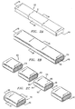
- electrosurgical electrode 10 is formed from an elongate stock material 50 (illustrated in Fig. 2A) that is coated with a non-stick layer 54 (illustrated in Fig. 2B) and formed into a plurality of electrode blanks 60 (illustrated in Fig. 2C). Electrode blank 60 may be directly inserted into handle 26 (FIG. 1) for electrical connection thereto or preferably electrode blank 60 may be finished creating electrosurgical electrode 10 (shown in FIG. 1) for insertion into handle 26 or the like.
- stock material 50 is made from medical grade stainless steel or an alloy thereof. Nickel and other highly conductive metals are also acceptable and have been found to work well in electrosurgical applications.
- Stock material 50 is configured and dimensioned to provide a plurality of electrode blanks 60.
- stainless steel stock material 50 is configured and dimensioned as sheet metal in the form of a coil 112.
- stainless steel stock material 50 is configured and dimensioned as sheet metal in the form of an elongated sheet 110.
- Each embodiment provides stock material 50 for mass manufacture of a plurality of electrode blanks 60.
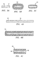
- a surface 51, shown in Figs. 2A, 3A and 4A, of stainless steel stock material 50 is generally smooth with a surface preparation, e.g., chemical etching, abrasive media, etc., so that a substantially uniform layer 54 of non-stick material may be applied.
- a surface preparation e.g., chemical etching, abrasive media, etc.
- stock material 50 is coated with a non-stick layer 54 for resisting eschar build up and improving ease of cleaning such buildup.
- the non-stick layer 54 includes a fluoropolymer or silicone layer. It is also contemplated that the non-stick layer may include a synthetic fluorine-based resin, a fluorinated hydrocarbon or silicone elastomers.
- the coating composition may also contain adhesion promoters, heat stabilizers, fillers, plasticizers, releasor enhancers, cross-linking agents, and colorants. Additionally, these coatings may come in the form of adhesives, dispersions or liquid rubbers.
- the coating step provides a uniform non-stick layer 54 over stainless steel stock material 50.
- Material 50 may be coated during a dipping step.
- the coating step may also include spraying a non-stick layer on the stainless steel material or manually applying a non-stick layer.
- a PTFE non-stick layer has a thickness of at least 1 ⁇ 2 mil up to a maximum thickness of 3 mils.
- the layer thickness may be varied at different locations on the stock material depending upon the blade's ultimate use and/or configuration.
- a plurality of electrode blanks 60 are formed from a non-coated stock material, as best shown in Fig. 2C.
- Formed electrode blanks 60 each have a top face 80, a bottom face 90, side faces 94, 98 and 99.
- side faces 98 and 99 will expose raw stock material 50, as shown in Fig. 2C and 4C.
- Top face 80, bottom face 90 and side faces 94 remain coated.
- Side face 99 exposes raw stock material 50 for contacting tissue to be treated.
- the remaining side face 98 is inserted into handle 26 for electrical contact and connection with electrosurgical instrument 15. It is envisioned that side faces 94 may also expose raw stock material 50 providing electrical contact and connection with instrument 15 or contact tissue targeted for treatment.
- An additional finishing step may include deburring of electrode blank 60 for removing rough portions formed on side faces 98 and 99 during forming.
- the step of finishing may also include tumbling the plurality of electrode blanks 60 with abrasive material media such as ceramic, plastic or steel to polish the mass manufactured plurality of electrodes blanks.
- abrasive material media such as ceramic, plastic or steel
- the finishing operation may further include buffing, belt grinding, belt sanding, surface grinding, plastic deformation, coining, burnishing, embossing or the like.
- Manipulating distal end 20 of electrosurgical electrode 10 for its particular application, such as threading, etching, knurling, or stamping is also contemplated.
- the forming step for mass manufacture includes a stamping operation.
- Stamping press 100 of Fig. 5B forms the plurality of electrode blanks 60 in the stamping operation.
- Stock material 50 is configured and dimensioned as an elongated sheet 110 to be fed through stamping press 100.
- Elongated sheet 110 is coated with a non-stick layer 54 prior to forming.
- Elongated sheet 110 is manually fed into stamping press 100 forming a plurality of electrode blanks 60.
- stock material 50 coated with non-stick layer 54, is configured and dimensioned as a coil 112 that is fed through stamping press 120 and 130 in a progressive stamping operation for forming the plurality of electrode blanks 60.
- electrode blanks 60 formed may be finished for use in electrosurgical procedures.
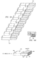
- stock material 50 is coil formed and configured and dimensioned as a tree 160, as illustrated in Fig. 6A.
- Tree 160 is partially coated with anon-stick layer 54, as shown in Fig. 6B. Only a portion 161 of tree 160 is coated. It is contemplated that varying portions of tree 160 may be coated for adaptability of tree 160 to various mass manufacturing processes known to one skilled in the art.
- Electrode blanks 164 illustrated in Fig. 6C, are formed from tree 160. Formed electrode blank 164 has a coated surface 166, further exemplified by non-stick layer 54 and faces 168 exposing raw stock material 50.
- tree 160 may be provided having substantially all of its outer surface coated with a non-stick layer.
- a subsequent finishing is provided to expose raw stock material.
- a proximal end 169 of electrode blank 164 shown in Fig. 6C, corresponding to proximal end portion 16 of electrosurgical electrode 10 of Fig. 1, is directly inserted into handle 26 of electrosurgical instrument 15.
- Proximal end 169 exposing raw stock material 50 provides an electrical connection for electrosurgical electrode 10 to electrosurgical instrument 15 through handle 26.
- An additional step of finishing may be included so that exposed face 169 is prepared for electrical connection to handle 26 of electrosurgical instrument 15 for improved conductivity.
- the finishing step may include deburring exposed face 168.
- a cut away portion 180 of tree 160 (shown in FIG. 6A) is illustrated in Fig. 7A.
- Stock material 50 having a non-stick layer 54 is configured and dimensioned as tree 160 for mass manufacturing a plurality of electrosurgical electrodes.
- FIG. 7B tree 160 is finished in a coining operation to embody electrosurgical blanks 190 that are connected to tree 160. Tree 160 may also be finished in a stamping operation or other deforming operation known to one skilled in the art for preparing electrosurgical blanks 190 for the particular electrosurgical application intended.
- Electrosurgical blades 200 are formed from tree 160, as shown in Fig. 7C. Electrosurgical blade 200 has a face 208 exposing raw stock material 50 for electrical connection to electrosurgical instrument 15 (as shown in Fig. 1). Faces 210 expose raw stock material 50 providing conductive contact sites for treating tissue.
Abstract
Description
- The present disclosure relates to coated electrosurgical electrodes and more particularly, to a method of mass manufacturing a plurality of electrosurgical blades having a non-stick coating that resists the build up of eschar and facilitates facile removal of eschar build-up.
- Electrosurgical electrodes and/or blades are used to cut and coagulate tissue. The electrodes conduct high frequency electrosurgical energy from an appropriate electrical power source to the patient. Many electrically powered instruments using electrosurgical electrodes, such as coagulation forceps, suction cauteries, electrode cautery tips and blades, are well-known.
- A working tip of the electrosurgical electrode is subject to high temperatures during use, particularly where an electrosurgical arc is generated, i.e. during fulguration or coagulation. These high temperatures cause the proteins, carbohydrates and lipids in the body to coagulate in the tissue as well as adhere to the working tip. This coagulant is commonly called eschar. Eschar that adheres to the working tip is undesirable because it may reduce cutting and coagulation performance.
- Coating an electrosurgical electrode to reduce eschar buildup and make the electrode easier to clean is known in the art. Various coatings are used with medical instruments to render the electrode surface less adherent and facilitate cleaning of the electrode tip. U.S. Patent No. 4,785,807 discloses an electrosurgical electrode having a first coat of primer material and a second coat of fluorinated hydrocarbon material with RF energy transferred to a treatment site through a capacitive coupling.
- Electrosurgical electrodes coated with a non-stick layer may be manufactured individually, i.e., producing one coated electrode per manufacturing process. U.S. Patent No. 5,702,387 assigned to Valleylab Inc. discloses an electrode blade having a silicone elastomer coating and alternative manufacturing techniques for producing the coated blades, including dip and spray coating the individual blades.
- Manufacturing techniques for producing an electrode blade having a non-stick coating, such as those disclosed in U.S. Patent No. 5,702,387 whereby a single coated electrode is produced per manufacturing process, are expensive and time consuming.
- Techniques for producing a plurality of electrodes per manufacturing process are also known. These techniques often utilize automated processes such as feeding a coated coil through a progressive stamping operation. Prior to stamping, the raw material coil is processed in a "coil coating" step whereby the coil is fed through rollers and a non-stick coating is applied to the coil sheet from a coating bath. For example, Application Serial No. 08,367,493 that issued as U.S. Patent No. 5,713,895 on February 3, 1998, discloses such a manufacturing technique for producing a plurality of electrode blades having a partial non-stick coating whereby conductive sites for contacting tissue may include peaks about the surface of the blade. Adjacent peaks define valleys upon which the non-stick coating primarily resides. That patent is hereby incorporated by reference in its entirety.
- The use of a partially coated electrode blade only provides tissue treatment at the exposed conductive sites. In some cases, the limited number of conductive sites may not provide a sufficient tissue treatment area for a particular surgical application, such as, e.g., where a greater amount of tissue requires treatment.
- Accordingly, a need exists for a method of mass manufacturing a plurality of electrosurgical electrodes coated with a non-stick layer that provides increased conductive contact area for tissue treatment and advantageously utilizes a mass manufacturing technique that increases the commercial viability of the non-stick coated electrode over the current state of the art.
- A method of mass manufacturing a plurality of electrosurgical electrodes coated with a non-stick layer is disclosed. The non-stick layer reduces eschar buildup and the like on the working tip of an electrode during electrosurgical procedures and facilitates ease of cleaning the tip.
- The method of mass manufacturing a plurality of electrosurgical electrodes includes the steps of: providing electrically conductive stock material, coating at least a portion of the stock material with a non-stick layer, and forming a plurality of electrode blanks having the non-stick layer. Thereafter, if desired, the blanks may be subjected to further finishing.
- It is contemplated that this method of mass manufacturing a plurality of electrodes may be used to make electrodes for surgical applications whereby each of the plurality of electrodes may be in the form of a blade, a knife, a loop or a ball.
- The stock material, preferably, is a medical grade sheet metal adapted for use in surgical applications and configured and dimensioned to provide a plurality of electrode blanks therefrom. Depending on the manner of forming the electrode blanks, various configurations and dimensions may be used for providing the stock material. It is contemplated that the stock material may be provided whereby it is configured and dimensioned in the form of a sheet metal blank, an elongated sheet of sheet metal or as elongated medical grade sheet metal wound into a coil.
- The method discloses coating at least a portion of the stock material with a non-stick layer that resists eschar buildup and makes the electrode easier to clean. The step of coating may include spraying, dipping and manually applying a non-stick layer on the material. The non-stick coating may include a synthetic fluorine based resin, polytetrafluoroethylene, fluorinated hydrocarbon, fluoropolymer, silicone, etc. A silicone coating may include, for example, silane, siloxane, polydimethylsiloxane, etc. In an alternate embodiment, the step of coating includes coating substantially all of the stock material with a non-stick layer. Subsequent thereto, a step of finishing is included to selectively remove a portion of the coating thereby exposing stock material for mechanical/electrical connection to a surgical instrument.
- Preferably, each of the plurality of electrode blanks formed has a top face and a bottom face coated with a non-stick layer. It is contemplated that, subsequent to forming, each of the plurality of electrodes will have at least one side face exposing raw stock material. Desirably, at least one exposed side face can be adapted for connection to an electrosurgical instrument.
- Finishing may include additional coating of one or more side faces with a layer of non-stick material.
- The step of finishing also contemplates deburring, buffing, belt grinding, belt sanding or surface grinding the electrode blanks with abrasive material media; plastically deforming, coining, burnishing, embossing, threading, etching, knurling, shot peening, plastically deforming, wire brushing and grit blasting, plasma spraying and electric arc spraying with conductive material; and/or high velocity oxygen fuel spraying at least a portion of each of the plurality of electrode blanks.
- Preferred embodiments of the present disclosure are described herein with reference to the drawings wherein:
- FIG. 1 is a perspective view of a mass manufactured non-stick coated electrosurgical electrode mounted in a handpiece;
- FIGS. 2A-D are illustrations showing an elongate portion of stock material for mass-producing non-stick coated electrosurgical electrodes coated and formed into electrode blanks and finished;
- FIGS. 3A-C are cross-sectional views taken along
lines 3A-3A, 3B-3B and 3C-3C of FIGS. 2A, 2B and 2D, respectively, showing a product of the method for mass producing the plurality of electrodes with a non-stick coating; - FIGS. 4A-D are a cross-sectional views taken along
lines 4A-4A, 4B-4B, 4C-4C and 4D-4D of FIGS. 2A, 2B and 2D, respectively, showing a product of the method for mass producing the plurality of electrodes with a non-stick coating; - FIG. 5A is a schematic illustration showing a method for mass producing a plurality of non-stick coated electrosurgical electrodes from a sheet metal coil;
- FIG. 5B is a schematic illustration showing a method for mass producing a plurality of non-stick coated electrosurgical electrodes from a sheet metal strip;
- FIG. 6A is a perspective view of stock material configured and dimensioned in the form of a tree to provide a plurality of electrode blanks connected to the tree for mass manufacture;
- FIG. 6B is a perspective cut-away view, in part cross-section, of a portion of the tree shown in FIG. 6A subsequent to the step of coating the stock material with a non-stick layer;
- FIG. 6C is a perspective view of one of a plurality of electrodes mass manufactured from stock material configured and dimensioned in the form of a tree;
- FIG. 7A is a perspective, cut away view of a portion of stock material configured and dimensioned in the form of the tree in FIG. 6A;
- FIG. 7B is a perspective, cut away view of the portion of stock material shown in FIG. 7A after a finishing step is performed; and
- FIG. 7C is a perspective cut away view of a mass manufactured electrode.
-
- Referring to Fig. 1, the present disclosure relates to a method of forming an electrosurgical electrode generally indicated at 10 having a
proximal end portion 16 for insertion into ahandle 26 or the like and a distal-end portion 20 including a working edge orsurface 22 for contacting tissue when theelectrosurgical blade 10 is in use. - The
proximal end portion 16 is inserted intohandle 26 and the appropriate electrical current is supplied from a power source (not shown) in a monopolar or bipolar circuit to theelectrosurgical blade 10 or other electrosurgical instrument to cut and/or coagulate a tissue site. Although anelectrosurgical blade 10 for cutting and cauterizing is disclosed and described, it is contemplated that the present disclosure is applicable to any electrosurgical instrument that comes into contact with tissue, such as coagulation forceps, suction cautery devices and electrode cautery tips. It is further contemplated that the electrosurgical electrode may comprise various electrosurgical tips such as balls, loops, hooks, etc. -
Electrosurgical blade 10 ofelectrosurgical instrument 15, as illustrated in Fig. 1, connects to a source of electromagnetic energy (not shown) for transmission of electromagnetic energy to the tissue. Non-stick coatedelectrosurgical electrode 10 applies electromagnetic energy during electro-surgery.Coated electrode 10 and its method of manufacture are described herein. - One preferred method of mass producing a plurality of electrosurgical electrodes includes the steps of simultaneously coating at least a portion of a conductive stock material with a non-stick layer; and forming the plurality of electrode blanks into electrodes having the non-stick layer. Finishing the plurality of electrode blanks may be accomplished thereafter if necessary, i.e., providing exposed material of the coated stock or deburring.
- In one embodiment, as shown in Figs. 2-4,
electrosurgical electrode 10 is formed from an elongate stock material 50 (illustrated in Fig. 2A) that is coated with a non-stick layer 54 (illustrated in Fig. 2B) and formed into a plurality of electrode blanks 60 (illustrated in Fig. 2C). Electrode blank 60 may be directly inserted into handle 26 (FIG. 1) for electrical connection thereto or preferably electrode blank 60 may be finished creating electrosurgical electrode 10 (shown in FIG. 1) for insertion intohandle 26 or the like. - Referring to Figs. 2A, 3A and 4A,
stock material 50 is made from medical grade stainless steel or an alloy thereof. Nickel and other highly conductive metals are also acceptable and have been found to work well in electrosurgical applications.Stock material 50 is configured and dimensioned to provide a plurality ofelectrode blanks 60. In another embodiment, as shown in Fig. 5A, stainlesssteel stock material 50 is configured and dimensioned as sheet metal in the form of acoil 112. In another embodiment shown in Fig. 5B, stainlesssteel stock material 50 is configured and dimensioned as sheet metal in the form of anelongated sheet 110. Each embodiment providesstock material 50 for mass manufacture of a plurality ofelectrode blanks 60. - A
surface 51, shown in Figs. 2A, 3A and 4A, of stainlesssteel stock material 50 is generally smooth with a surface preparation, e.g., chemical etching, abrasive media, etc., so that a substantiallyuniform layer 54 of non-stick material may be applied. With reference to Figs. 2B, 3B and 4B,stock material 50 is coated with anon-stick layer 54 for resisting eschar build up and improving ease of cleaning such buildup. Thenon-stick layer 54 includes a fluoropolymer or silicone layer. It is also contemplated that the non-stick layer may include a synthetic fluorine-based resin, a fluorinated hydrocarbon or silicone elastomers. The coating composition may also contain adhesion promoters, heat stabilizers, fillers, plasticizers, releasor enhancers, cross-linking agents, and colorants. Additionally, these coatings may come in the form of adhesives, dispersions or liquid rubbers. - The coating step provides a uniform
non-stick layer 54 over stainlesssteel stock material 50.Material 50 may be coated during a dipping step. The coating step may also include spraying a non-stick layer on the stainless steel material or manually applying a non-stick layer. Preferably, a PTFE non-stick layer has a thickness of at least ½ mil up to a maximum thickness of 3 mils. A non-stick layer including silicone, preferably, has a range of thickness from ½ mil to 10 mils. It is also envisioned that the non-stick layer may be applied to the stock by vapor deposition having a thickness in the micromolecular range to approximately 1/10 mil. It is further contemplated that the layer thickness may be varied at different locations on the stock material depending upon the blade's ultimate use and/or configuration. Subsequent to providing and coating the material, a plurality ofelectrode blanks 60 are formed from a non-coated stock material, as best shown in Fig. 2C. Formedelectrode blanks 60 each have atop face 80, abottom face 90, side faces 94, 98 and 99. Once formed intoindividual electrode blanks 60, side faces 98 and 99 will exposeraw stock material 50, as shown in Fig. 2C and 4C.Top face 80,bottom face 90 and side faces 94 remain coated. - Side face 99 exposes
raw stock material 50 for contacting tissue to be treated. The remainingside face 98, is inserted intohandle 26 for electrical contact and connection withelectrosurgical instrument 15. It is envisioned that side faces 94 may also exposeraw stock material 50 providing electrical contact and connection withinstrument 15 or contact tissue targeted for treatment. - An additional finishing step may include deburring of electrode blank 60 for removing rough portions formed on side faces 98 and 99 during forming.
- The step of finishing may also include tumbling the plurality of
electrode blanks 60 with abrasive material media such as ceramic, plastic or steel to polish the mass manufactured plurality of electrodes blanks. - The finishing operation may further include buffing, belt grinding, belt sanding, surface grinding, plastic deformation, coining, burnishing, embossing or the like. Manipulating
distal end 20 ofelectrosurgical electrode 10 for its particular application, such as threading, etching, knurling, or stamping is also contemplated. - In another preferred embodiment, as shown in Figs. 5A and SB, the forming step for mass manufacture includes a stamping operation. Stamping
press 100 of Fig. 5B forms the plurality ofelectrode blanks 60 in the stamping operation.Stock material 50 is configured and dimensioned as anelongated sheet 110 to be fed through stampingpress 100.Elongated sheet 110 is coated with anon-stick layer 54 prior to forming.Elongated sheet 110 is manually fed into stampingpress 100 forming a plurality ofelectrode blanks 60. - In yet another embodiment shown in Fig. 5A,
stock material 50, coated withnon-stick layer 54, is configured and dimensioned as acoil 112 that is fed through stampingpress electrode blanks 60. In either of the forming steps, including a stamping operation described above,electrode blanks 60 formed may be finished for use in electrosurgical procedures. - In another preferred embodiment,
stock material 50 is coil formed and configured and dimensioned as atree 160, as illustrated in Fig. 6A.Tree 160 is partially coated with anon-stick layer 54, as shown in Fig. 6B. Only aportion 161 oftree 160 is coated. It is contemplated that varying portions oftree 160 may be coated for adaptability oftree 160 to various mass manufacturing processes known to one skilled in the art.Electrode blanks 164, illustrated in Fig. 6C, are formed fromtree 160. Formedelectrode blank 164 has acoated surface 166, further exemplified bynon-stick layer 54 and faces 168 exposingraw stock material 50. - It is also envisioned that
tree 160 may be provided having substantially all of its outer surface coated with a non-stick layer. Preferably, a subsequent finishing is provided to expose raw stock material. - A
proximal end 169 of electrode blank 164 shown in Fig. 6C, corresponding toproximal end portion 16 ofelectrosurgical electrode 10 of Fig. 1, is directly inserted intohandle 26 ofelectrosurgical instrument 15.Proximal end 169 exposingraw stock material 50 provides an electrical connection forelectrosurgical electrode 10 toelectrosurgical instrument 15 throughhandle 26. - An additional step of finishing may be included so that exposed
face 169 is prepared for electrical connection to handle 26 ofelectrosurgical instrument 15 for improved conductivity. The finishing step may include deburring exposedface 168. - In yet another embodiment, a cut away
portion 180 of tree 160 (shown in FIG. 6A) is illustrated in Fig. 7A.Stock material 50 having anon-stick layer 54 is configured and dimensioned astree 160 for mass manufacturing a plurality of electrosurgical electrodes. - As shown in Fig. 7B,
tree 160 is finished in a coining operation to embodyelectrosurgical blanks 190 that are connected totree 160.Tree 160 may also be finished in a stamping operation or other deforming operation known to one skilled in the art for preparingelectrosurgical blanks 190 for the particular electrosurgical application intended.Electrosurgical blades 200 are formed fromtree 160, as shown in Fig. 7C.Electrosurgical blade 200 has aface 208 exposingraw stock material 50 for electrical connection to electrosurgical instrument 15 (as shown in Fig. 1).Faces 210 exposeraw stock material 50 providing conductive contact sites for treating tissue. - Therefore, it is understood that various modifications may be made to the embodiments disclosed herein. For example, while specific preferred embodiments of the method of mass manufacturing a plurality of electrosurgical electrodes have been described in detail, structures that perform the same function in substantially the same way to achieve substantially the same result may also be used. For example, the stock material may have a rough surface. Further, electrode blanks may contact the tree at more than one face. Therefore, the above description should not be construed as limiting, but merely as exemplifications of preferred embodiments. Those skilled in the art will envision other modifications within the scope and spirit of the present disclosure.
Claims (18)
- A method of mass manufacturing a plurality of electrodes, each electrode mass manufactured for connection to an appropriate electrical power source for a surgical procedure, the method comprising the steps of:providing electrically conductive stock material, whereby the stock material is configured and dimensioned to provide a plurality of electrode blanks;coating at least a portion of the stock material with a non-stick layer; andforming the plurality of coated electrode blanks.
- The method according to claim 1, further comprising the step of finishing the plurality of electrode blanks.
- The method according to claim 1, whereby the step of forming includes forming the stock material into a plurality of electrode blades.
- The method according to claim 1, whereby the step of forming includes forming each of the plurality of electrode blanks with at least one uncoated side face exposing stock material.
- The method according to claim 1, whereby the step of providing electrically conductive stock material comprises stock material configured and dimensioned as a tree wherein each of the plurality of electrode blanks arc connected to the tree by at least one face.
- The method of manufacturing according to claim 1, wherein the step of providing electrically conductive stock material comprises stock material configured and dimensioned as a sheet that is wound into a coil.
- The method according to claim 1, wherein the step of providing electrically conductive stock material comprises stock material configured and dimensioned as a sheet in the form of a blank.
- The method according to claim 1, wherein the step of coating comprises the step of coating the stock material with at least one non-stick layer selected from the group consisting of synthetic fluorine based resins, fluorinated carbons and silicone elastomers.
- The method according to claim 8, wherein the non-stick layer comprises polytetrafluoroethylene.
- The method according to claim 4, wherein the step of finishing includes coating any of the uncoated side faces exposing stock material with a layer of non-stick material.
- The method according to claim 1, wherein the step of forming comprises a stamping operation.
- A method of mass manufacturing a plurality of electrodes, each electrode mass manufactured for connection to an appropriate electrical power source for a surgical procedure, the method comprising the steps of:wherein the plurality of electrode blanks are formed having the non-stick layer as the material is advanced through the stamping operation; andproviding electrically conductive stock material, whereby the stock material is configured and dimensioned to provide a plurality of electrode blanks;coating at least a portion of the stock material with a non-stick layer;feeding the stock material having the non-stick layer to a stamping operation, wherein the stock material is configured and dimensioned for receipt by the stamping operation;forming the plurality of electrode blanks having the non-stick layer,
finishing the plurality of electrode blanks. - The method according to claim 12, wherein the step of providing electrically conductive stock material further comprises stock material configured and dimensioned as a coil of sheet metal, the step of feeding further comprises configuring the coil for the stamping operation, and the step of forming further comprises advancing the coil through the stamping operation.
- The method according to claim 12, wherein the step of providing electrically conductive stock material further comprises stock material configured and dimensioned as an elongated sheet metal, the step of feeding further comprises adapting the elongated sheet for the stamping operation, and the step of forming further comprises advancing the elongated sheet through the stamping operation.
- The method according to claim 12, wherein the step of providing electrically conductive stock material further comprises the material configured and dimensioned as a sheet metal blank and the step of feeding further comprises adapting the sheet metal blank for use with the stamping operation.
- A method of mass manufacturing a plurality of electrodes, each electrode mass manufactured for connection to an appropriate electrical power source for a surgical procedure, the method comprising the steps of:providing electrically conductive stock material, whereby the stock material is configured and dimensioned as a tree to provide a plurality of electrode blanks, whereby each of the plurality of electrode blanks are connected to the tree by at least one face;coating at least a portion of the tree with a non-stick layer; andforming the plurality of electrode blanks having the non-stick layer.
- The method according to claim 16, further comprising the step of finishing the tree.
- The method according to claim 17, wherein the step of finishing the tree comprises removing at least a portion of the coating.
Applications Claiming Priority (2)
| Application Number | Priority Date | Filing Date | Title |
|---|---|---|---|
| US282812 | 1999-03-31 | ||
| US09/282,812 US6070444A (en) | 1999-03-31 | 1999-03-31 | Method of mass manufacturing coated electrosurgical electrodes |
Publications (2)
| Publication Number | Publication Date |
|---|---|
| EP1040793A1 true EP1040793A1 (en) | 2000-10-04 |
| EP1040793B1 EP1040793B1 (en) | 2007-05-09 |
Family
ID=23083226
Family Applications (1)
| Application Number | Title | Priority Date | Filing Date |
|---|---|---|---|
| EP00104553A Expired - Lifetime EP1040793B1 (en) | 1999-03-31 | 2000-03-13 | Method of mass manufacturing coated electrosurgical electrodes |
Country Status (6)
| Country | Link |
|---|---|
| US (1) | US6070444A (en) |
| EP (1) | EP1040793B1 (en) |
| JP (1) | JP2000333968A (en) |
| CA (1) | CA2300357C (en) |
| DE (1) | DE60034728T2 (en) |
| ES (1) | ES2282066T3 (en) |
Families Citing this family (53)
| Publication number | Priority date | Publication date | Assignee | Title |
|---|---|---|---|---|
| US6511479B2 (en) | 2000-02-28 | 2003-01-28 | Conmed Corporation | Electrosurgical blade having directly adhered uniform coating of silicone release material and method of manufacturing same |
| DE60113150T2 (en) * | 2000-12-15 | 2006-06-29 | Sherwood Services Ag | ELECTRO-SURGICAL ELECTRODE PROTECTION COLLAR |
| US6540745B1 (en) * | 2001-05-01 | 2003-04-01 | Aeromet Technologies, Inc. | Coated medical devices |
| CA2493556C (en) * | 2002-07-25 | 2012-04-03 | Thomas L. Ii Buchman | Electrosurgical pencil with drag sensing capability |
| US6747218B2 (en) | 2002-09-20 | 2004-06-08 | Sherwood Services Ag | Electrosurgical haptic switch including snap dome and printed circuit stepped contact array |
| US7244257B2 (en) | 2002-11-05 | 2007-07-17 | Sherwood Services Ag | Electrosurgical pencil having a single button variable control |
| US20040115477A1 (en) * | 2002-12-12 | 2004-06-17 | Bruce Nesbitt | Coating reinforcing underlayment and method of manufacturing same |
| US7235072B2 (en) | 2003-02-20 | 2007-06-26 | Sherwood Services Ag | Motion detector for controlling electrosurgical output |
| US7217270B2 (en) * | 2003-09-08 | 2007-05-15 | Mectra Labs, Inc. | Method and material for coating electro-cautery probes and lubricating surgical instruments |
| US7156842B2 (en) * | 2003-11-20 | 2007-01-02 | Sherwood Services Ag | Electrosurgical pencil with improved controls |
| US7503917B2 (en) | 2003-11-20 | 2009-03-17 | Covidien Ag | Electrosurgical pencil with improved controls |
| US7156844B2 (en) * | 2003-11-20 | 2007-01-02 | Sherwood Services Ag | Electrosurgical pencil with improved controls |
| US7879033B2 (en) | 2003-11-20 | 2011-02-01 | Covidien Ag | Electrosurgical pencil with advanced ES controls |
| US7182762B2 (en) * | 2003-12-30 | 2007-02-27 | Smith & Nephew, Inc. | Electrosurgical device |
| US20060235378A1 (en) * | 2005-04-18 | 2006-10-19 | Sherwood Services Ag | Slider control for ablation handset |
| US8814861B2 (en) | 2005-05-12 | 2014-08-26 | Innovatech, Llc | Electrosurgical electrode and method of manufacturing same |
| US7147634B2 (en) * | 2005-05-12 | 2006-12-12 | Orion Industries, Ltd. | Electrosurgical electrode and method of manufacturing same |
| US7500974B2 (en) * | 2005-06-28 | 2009-03-10 | Covidien Ag | Electrode with rotatably deployable sheath |
| US7828794B2 (en) | 2005-08-25 | 2010-11-09 | Covidien Ag | Handheld electrosurgical apparatus for controlling operating room equipment |
| US20070260240A1 (en) | 2006-05-05 | 2007-11-08 | Sherwood Services Ag | Soft tissue RF transection and resection device |
| US20080188845A1 (en) * | 2007-02-01 | 2008-08-07 | Mcgreevy Francis T | Tissue fusion instrument and method to reduce the adhesion of tissue to its working surfaces |
| US8361070B2 (en) | 2007-02-19 | 2013-01-29 | Synergetics, Inc. | Non-stick bipolar forceps |
| US8506565B2 (en) | 2007-08-23 | 2013-08-13 | Covidien Lp | Electrosurgical device with LED adapter |
| US8235987B2 (en) | 2007-12-05 | 2012-08-07 | Tyco Healthcare Group Lp | Thermal penetration and arc length controllable electrosurgical pencil |
| CN102027574B (en) * | 2008-02-08 | 2014-09-10 | 朗姆研究公司 | A protective coating for a plasma processing chamber part and a method of use |
| US8663218B2 (en) | 2008-03-31 | 2014-03-04 | Covidien Lp | Electrosurgical pencil including improved controls |
| US8636733B2 (en) | 2008-03-31 | 2014-01-28 | Covidien Lp | Electrosurgical pencil including improved controls |
| US8597292B2 (en) | 2008-03-31 | 2013-12-03 | Covidien Lp | Electrosurgical pencil including improved controls |
| EP2319447B1 (en) | 2008-03-31 | 2012-08-22 | Applied Medical Resources Corporation | Electrosurgical tool with jaws actuatable by a force regulation mechanism |
| US8162937B2 (en) | 2008-06-27 | 2012-04-24 | Tyco Healthcare Group Lp | High volume fluid seal for electrosurgical handpiece |
| US8303582B2 (en) | 2008-09-15 | 2012-11-06 | Tyco Healthcare Group Lp | Electrosurgical instrument having a coated electrode utilizing an atomic layer deposition technique |
| US8231620B2 (en) | 2009-02-10 | 2012-07-31 | Tyco Healthcare Group Lp | Extension cutting blade |
| ES2664081T3 (en) | 2010-10-01 | 2018-04-18 | Applied Medical Resources Corporation | Electrosurgical system with a radio frequency amplifier and with means for adapting to the separation between electrodes |
| US8595921B2 (en) * | 2010-11-17 | 2013-12-03 | Rsr Technologies, Inc. | Electrodes made using surfacing technique and method of manufacturing the same |
| JP6573663B2 (en) | 2014-05-16 | 2019-09-11 | アプライド メディカル リソーシーズ コーポレイション | Electrosurgical system |
| AU2015266619B2 (en) | 2014-05-30 | 2020-02-06 | Applied Medical Resources Corporation | Electrosurgical instrument for fusing and cutting tissue and an electrosurgical generator |
| EP3236870B1 (en) | 2014-12-23 | 2019-11-06 | Applied Medical Resources Corporation | Bipolar electrosurgical sealer and divider |
| USD748259S1 (en) | 2014-12-29 | 2016-01-26 | Applied Medical Resources Corporation | Electrosurgical instrument |
| WO2017031712A1 (en) | 2015-08-26 | 2017-03-02 | Covidien Lp | Electrosurgical end effector assemblies and electrosurgical forceps configured to reduce thermal spread |
| US10368939B2 (en) | 2015-10-29 | 2019-08-06 | Covidien Lp | Non-stick coated electrosurgical instruments and method for manufacturing the same |
| US10441349B2 (en) | 2015-10-29 | 2019-10-15 | Covidien Lp | Non-stick coated electrosurgical instruments and method for manufacturing the same |
| US11432869B2 (en) | 2017-09-22 | 2022-09-06 | Covidien Lp | Method for coating electrosurgical tissue sealing device with non-stick coating |
| US10709497B2 (en) | 2017-09-22 | 2020-07-14 | Covidien Lp | Electrosurgical tissue sealing device with non-stick coating |
| US11648047B2 (en) | 2017-10-06 | 2023-05-16 | Vive Scientific, Llc | System and method to treat obstructive sleep apnea |
| WO2020027341A1 (en) | 2018-08-03 | 2020-02-06 | 日本パーカライジング株式会社 | Surgical electrode having surface treatment coating |
| CA3111558A1 (en) | 2018-09-05 | 2020-03-12 | Applied Medical Resources Corporation | Electrosurgical generator control system |
| US11696796B2 (en) | 2018-11-16 | 2023-07-11 | Applied Medical Resources Corporation | Electrosurgical system |
| WO2020205489A1 (en) * | 2019-03-29 | 2020-10-08 | Conmed Corporation | High permittivity electrosurgical electrode coating |
| US11207124B2 (en) | 2019-07-08 | 2021-12-28 | Covidien Lp | Electrosurgical system for use with non-stick coated electrodes |
| US11564732B2 (en) | 2019-12-05 | 2023-01-31 | Covidien Lp | Tensioning mechanism for bipolar pencil |
| US11369427B2 (en) | 2019-12-17 | 2022-06-28 | Covidien Lp | System and method of manufacturing non-stick coated electrodes |
| US11864817B2 (en) * | 2020-02-13 | 2024-01-09 | Covidien Lp | Low profile single pole tip for bipolar pencil |
| EP4104782A4 (en) * | 2020-02-13 | 2023-07-26 | Nihon Parkerizing Co., Ltd. | Electrosurgical electrode |
Citations (7)
| Publication number | Priority date | Publication date | Assignee | Title |
|---|---|---|---|---|
| US4161950A (en) * | 1975-08-01 | 1979-07-24 | The United States Of America As Represented By The United States Department Of Energy | Electrosurgical knife |
| US4785807A (en) | 1987-02-24 | 1988-11-22 | American Medical Products, Inc. | Electrosurgical knife |
| US5643256A (en) * | 1995-05-19 | 1997-07-01 | Urueta; R. Wilfrido | Gold-plated electrosurgical instrument |
| US5702387A (en) | 1995-09-27 | 1997-12-30 | Valleylab Inc | Coated electrosurgical electrode |
| US5713895A (en) | 1994-12-30 | 1998-02-03 | Valleylab Inc | Partially coated electrodes |
| US5800427A (en) * | 1996-12-26 | 1998-09-01 | Zamba; Gene | Electro-surgical blade |
| US5925043A (en) * | 1997-04-30 | 1999-07-20 | Medquest Products, Inc. | Electrosurgical electrode with a conductive, non-stick coating |
Family Cites Families (18)
| Publication number | Priority date | Publication date | Assignee | Title |
|---|---|---|---|---|
| US3460539A (en) * | 1967-03-10 | 1969-08-12 | James E Anhalt Sr | Cautery tip |
| US4232676A (en) * | 1978-11-16 | 1980-11-11 | Corning Glass Works | Surgical cutting instrument |
| US4314559A (en) * | 1979-12-12 | 1982-02-09 | Corning Glass Works | Nonstick conductive coating |
| US4492231A (en) * | 1982-09-17 | 1985-01-08 | Auth David C | Non-sticking electrocautery system and forceps |
| US4862890A (en) * | 1988-02-29 | 1989-09-05 | Everest Medical Corporation | Electrosurgical spatula blade with ceramic substrate |
| US4850353A (en) * | 1988-08-08 | 1989-07-25 | Everest Medical Corporation | Silicon nitride electrosurgical blade |
| US5100402A (en) * | 1990-10-05 | 1992-03-31 | Megadyne Medical Products, Inc. | Electrosurgical laparoscopic cauterization electrode |
| US5197962A (en) * | 1991-06-05 | 1993-03-30 | Megadyne Medical Products, Inc. | Composite electrosurgical medical instrument |
| US5262241A (en) * | 1991-08-26 | 1993-11-16 | Eeonyx Corporation | Surface coated products |
| JP3229020B2 (en) * | 1992-06-05 | 2001-11-12 | 大豊工業株式会社 | Slide bearing material |
| US5697926A (en) * | 1992-12-17 | 1997-12-16 | Megadyne Medical Products, Inc. | Cautery medical instrument |
| US5395363A (en) * | 1993-06-29 | 1995-03-07 | Utah Medical Products | Diathermy coagulation and ablation apparatus and method |
| US5380320A (en) * | 1993-11-08 | 1995-01-10 | Advanced Surgical Materials, Inc. | Electrosurgical instrument having a parylene coating |
| US5382247A (en) * | 1994-01-21 | 1995-01-17 | Valleylab Inc. | Technique for electrosurgical tips and method of manufacture and use |
| US5765418A (en) * | 1994-05-16 | 1998-06-16 | Medtronic, Inc. | Method for making an implantable medical device from a refractory metal |
| US5549604A (en) * | 1994-12-06 | 1996-08-27 | Conmed Corporation | Non-Stick electroconductive amorphous silica coating |
| US5693052A (en) * | 1995-09-01 | 1997-12-02 | Megadyne Medical Products, Inc. | Coated bipolar electrocautery |
| US5693050A (en) * | 1995-11-07 | 1997-12-02 | Aaron Medical Industries, Inc. | Electrosurgical instrument |
-
1999
- 1999-03-31 US US09/282,812 patent/US6070444A/en not_active Expired - Lifetime
-
2000
- 2000-03-10 CA CA2300357A patent/CA2300357C/en not_active Expired - Fee Related
- 2000-03-13 ES ES00104553T patent/ES2282066T3/en not_active Expired - Lifetime
- 2000-03-13 JP JP2000115912A patent/JP2000333968A/en active Pending
- 2000-03-13 EP EP00104553A patent/EP1040793B1/en not_active Expired - Lifetime
- 2000-03-13 DE DE60034728T patent/DE60034728T2/en not_active Expired - Lifetime
Patent Citations (8)
| Publication number | Priority date | Publication date | Assignee | Title |
|---|---|---|---|---|
| US4161950A (en) * | 1975-08-01 | 1979-07-24 | The United States Of America As Represented By The United States Department Of Energy | Electrosurgical knife |
| US4785807A (en) | 1987-02-24 | 1988-11-22 | American Medical Products, Inc. | Electrosurgical knife |
| US4785807B1 (en) | 1987-02-24 | 1996-07-16 | American Medical Products Inc | Electrosurgical knife |
| US5713895A (en) | 1994-12-30 | 1998-02-03 | Valleylab Inc | Partially coated electrodes |
| US5643256A (en) * | 1995-05-19 | 1997-07-01 | Urueta; R. Wilfrido | Gold-plated electrosurgical instrument |
| US5702387A (en) | 1995-09-27 | 1997-12-30 | Valleylab Inc | Coated electrosurgical electrode |
| US5800427A (en) * | 1996-12-26 | 1998-09-01 | Zamba; Gene | Electro-surgical blade |
| US5925043A (en) * | 1997-04-30 | 1999-07-20 | Medquest Products, Inc. | Electrosurgical electrode with a conductive, non-stick coating |
Also Published As
| Publication number | Publication date |
|---|---|
| ES2282066T3 (en) | 2007-10-16 |
| EP1040793B1 (en) | 2007-05-09 |
| DE60034728T2 (en) | 2008-01-31 |
| JP2000333968A (en) | 2000-12-05 |
| DE60034728D1 (en) | 2007-06-21 |
| US6070444A (en) | 2000-06-06 |
| CA2300357A1 (en) | 2000-09-13 |
| CA2300357C (en) | 2011-01-11 |
Similar Documents
| Publication | Publication Date | Title |
|---|---|---|
| EP1040793B1 (en) | Method of mass manufacturing coated electrosurgical electrodes | |
| US5713895A (en) | Partially coated electrodes | |
| EP1330990B1 (en) | Coated electrosurgical electrode | |
| US5697926A (en) | Cautery medical instrument | |
| EP1017324B1 (en) | Gold-plated electrosurgical instrument | |
| US5893846A (en) | Ceramic coated endoscopic scissor blades and a method of making the same | |
| EP1259183B1 (en) | Electrosurgical blade with direct adhesion of silicone coating | |
| US8814863B2 (en) | Electrosurgical electrode and method of manufacturing same | |
| JP5389542B2 (en) | Electrode for medical device and medical treatment tool | |
| AU2018348400B2 (en) | An electrode for an electrosurgical pencil and a method of making an electrode | |
| CN216090687U (en) | Ultrasonic treatment device with anti-adhesion coating | |
| KR20220127903A (en) | electrosurgical electrode | |
| CA2205847A1 (en) | Partially coated electrodes, manufacture and use | |
| US7761970B1 (en) | Method of manufacturing of electrosurgical implements | |
| JPH08196542A (en) | Appliance for surgery | |
| CN113576602A (en) | Ultrasonic treatment device with anti-adhesion coating | |
| JP2010227365A (en) | Electrode for medical device and medical treatment instrument |
Legal Events
| Date | Code | Title | Description |
|---|---|---|---|
| PUAI | Public reference made under article 153(3) epc to a published international application that has entered the european phase |
Free format text: ORIGINAL CODE: 0009012 |
|
| AK | Designated contracting states |
Kind code of ref document: A1 Designated state(s): DE ES FR GB IT |
|
| AX | Request for extension of the european patent |
Free format text: AL;LT;LV;MK;RO;SI |
|
| 17P | Request for examination filed |
Effective date: 20001103 |
|
| AKX | Designation fees paid |
Free format text: DE ES FR GB IT |
|
| 17Q | First examination report despatched |
Effective date: 20031103 |
|
| GRAP | Despatch of communication of intention to grant a patent |
Free format text: ORIGINAL CODE: EPIDOSNIGR1 |
|
| RAP1 | Party data changed (applicant data changed or rights of an application transferred) |
Owner name: SHERWOOD SERVICES AG |
|
| GRAS | Grant fee paid |
Free format text: ORIGINAL CODE: EPIDOSNIGR3 |
|
| GRAA | (expected) grant |
Free format text: ORIGINAL CODE: 0009210 |
|
| AK | Designated contracting states |
Kind code of ref document: B1 Designated state(s): DE ES FR GB IT |
|
| REG | Reference to a national code |
Ref country code: GB Ref legal event code: FG4D |
|
| REF | Corresponds to: |
Ref document number: 60034728 Country of ref document: DE Date of ref document: 20070621 Kind code of ref document: P |
|
| RAP2 | Party data changed (patent owner data changed or rights of a patent transferred) |
Owner name: COVIDIEN AG |
|
| REG | Reference to a national code |
Ref country code: ES Ref legal event code: FG2A Ref document number: 2282066 Country of ref document: ES Kind code of ref document: T3 |
|
| ET | Fr: translation filed | ||
| PLBE | No opposition filed within time limit |
Free format text: ORIGINAL CODE: 0009261 |
|
| STAA | Information on the status of an ep patent application or granted ep patent |
Free format text: STATUS: NO OPPOSITION FILED WITHIN TIME LIMIT |
|
| 26N | No opposition filed |
Effective date: 20080212 |
|
| REG | Reference to a national code |
Ref country code: FR Ref legal event code: CA Ref country code: FR Ref legal event code: CD |
|
| PGFP | Annual fee paid to national office [announced via postgrant information from national office to epo] |
Ref country code: IT Payment date: 20120326 Year of fee payment: 13 |
|
| PGFP | Annual fee paid to national office [announced via postgrant information from national office to epo] |
Ref country code: GB Payment date: 20130327 Year of fee payment: 14 Ref country code: DE Payment date: 20130327 Year of fee payment: 14 Ref country code: ES Payment date: 20130326 Year of fee payment: 14 Ref country code: FR Payment date: 20130405 Year of fee payment: 14 |
|
| REG | Reference to a national code |
Ref country code: DE Ref legal event code: R119 Ref document number: 60034728 Country of ref document: DE |
|
| GBPC | Gb: european patent ceased through non-payment of renewal fee |
Effective date: 20140313 |
|
| REG | Reference to a national code |
Ref country code: FR Ref legal event code: ST Effective date: 20141128 |
|
| REG | Reference to a national code |
Ref country code: DE Ref legal event code: R119 Ref document number: 60034728 Country of ref document: DE Effective date: 20141001 |
|
| PG25 | Lapsed in a contracting state [announced via postgrant information from national office to epo] |
Ref country code: FR Free format text: LAPSE BECAUSE OF NON-PAYMENT OF DUE FEES Effective date: 20140331 Ref country code: GB Free format text: LAPSE BECAUSE OF NON-PAYMENT OF DUE FEES Effective date: 20140313 Ref country code: DE Free format text: LAPSE BECAUSE OF NON-PAYMENT OF DUE FEES Effective date: 20141001 |
|
| PG25 | Lapsed in a contracting state [announced via postgrant information from national office to epo] |
Ref country code: IT Free format text: LAPSE BECAUSE OF NON-PAYMENT OF DUE FEES Effective date: 20140313 |
|
| REG | Reference to a national code |
Ref country code: ES Ref legal event code: FD2A Effective date: 20150427 |
|
| PG25 | Lapsed in a contracting state [announced via postgrant information from national office to epo] |
Ref country code: ES Free format text: LAPSE BECAUSE OF NON-PAYMENT OF DUE FEES Effective date: 20140314 |