EP1040901B1 - Method and device for forming a compound material - Google Patents
Method and device for forming a compound material Download PDFInfo
- Publication number
- EP1040901B1 EP1040901B1 EP00105122A EP00105122A EP1040901B1 EP 1040901 B1 EP1040901 B1 EP 1040901B1 EP 00105122 A EP00105122 A EP 00105122A EP 00105122 A EP00105122 A EP 00105122A EP 1040901 B1 EP1040901 B1 EP 1040901B1
- Authority
- EP
- European Patent Office
- Prior art keywords
- downstream
- pinching
- tension
- upstream
- compound material
- Prior art date
- Legal status (The legal status is an assumption and is not a legal conclusion. Google has not performed a legal analysis and makes no representation as to the accuracy of the status listed.)
- Expired - Lifetime
Links
- 239000000463 material Substances 0.000 title claims description 108
- 150000001875 compounds Chemical class 0.000 title claims description 64
- 238000000034 method Methods 0.000 title claims description 23
- 238000011144 upstream manufacturing Methods 0.000 claims description 48
- 239000000835 fiber Substances 0.000 claims description 47
- 239000002131 composite material Substances 0.000 claims description 38
- 238000010438 heat treatment Methods 0.000 claims description 27
- 229920005989 resin Polymers 0.000 description 10
- 239000011347 resin Substances 0.000 description 10
- 229920000049 Carbon (fiber) Polymers 0.000 description 6
- 239000004917 carbon fiber Substances 0.000 description 6
- 238000013007 heat curing Methods 0.000 description 5
- 230000002787 reinforcement Effects 0.000 description 5
- 230000006835 compression Effects 0.000 description 3
- 238000007906 compression Methods 0.000 description 3
- 239000003365 glass fiber Substances 0.000 description 3
- 238000004458 analytical method Methods 0.000 description 2
- 238000004519 manufacturing process Methods 0.000 description 2
- 238000004364 calculation method Methods 0.000 description 1
- 238000006243 chemical reaction Methods 0.000 description 1
- 230000008602 contraction Effects 0.000 description 1
- 238000001816 cooling Methods 0.000 description 1
- 238000001723 curing Methods 0.000 description 1
- 230000006866 deterioration Effects 0.000 description 1
- 238000010586 diagram Methods 0.000 description 1
- 238000006073 displacement reaction Methods 0.000 description 1
- 239000003822 epoxy resin Substances 0.000 description 1
- 238000002474 experimental method Methods 0.000 description 1
- 239000011159 matrix material Substances 0.000 description 1
- 238000001000 micrograph Methods 0.000 description 1
- 238000000465 moulding Methods 0.000 description 1
- 239000004033 plastic Substances 0.000 description 1
- 229920000647 polyepoxide Polymers 0.000 description 1
- 230000003014 reinforcing effect Effects 0.000 description 1
- 239000012783 reinforcing fiber Substances 0.000 description 1
- 239000012779 reinforcing material Substances 0.000 description 1
Images


Classifications
-
- B—PERFORMING OPERATIONS; TRANSPORTING
- B29—WORKING OF PLASTICS; WORKING OF SUBSTANCES IN A PLASTIC STATE IN GENERAL
- B29C—SHAPING OR JOINING OF PLASTICS; SHAPING OF MATERIAL IN A PLASTIC STATE, NOT OTHERWISE PROVIDED FOR; AFTER-TREATMENT OF THE SHAPED PRODUCTS, e.g. REPAIRING
- B29C70/00—Shaping composites, i.e. plastics material comprising reinforcements, fillers or preformed parts, e.g. inserts
- B29C70/04—Shaping composites, i.e. plastics material comprising reinforcements, fillers or preformed parts, e.g. inserts comprising reinforcements only, e.g. self-reinforcing plastics
- B29C70/28—Shaping operations therefor
- B29C70/40—Shaping or impregnating by compression not applied
- B29C70/50—Shaping or impregnating by compression not applied for producing articles of indefinite length, e.g. prepregs, sheet moulding compounds [SMC] or cross moulding compounds [XMC]
- B29C70/52—Pultrusion, i.e. forming and compressing by continuously pulling through a die
- B29C70/525—Component parts, details or accessories; Auxiliary operations
- B29C70/527—Pulling means
-
- B—PERFORMING OPERATIONS; TRANSPORTING
- B29—WORKING OF PLASTICS; WORKING OF SUBSTANCES IN A PLASTIC STATE IN GENERAL
- B29C—SHAPING OR JOINING OF PLASTICS; SHAPING OF MATERIAL IN A PLASTIC STATE, NOT OTHERWISE PROVIDED FOR; AFTER-TREATMENT OF THE SHAPED PRODUCTS, e.g. REPAIRING
- B29C70/00—Shaping composites, i.e. plastics material comprising reinforcements, fillers or preformed parts, e.g. inserts
- B29C70/04—Shaping composites, i.e. plastics material comprising reinforcements, fillers or preformed parts, e.g. inserts comprising reinforcements only, e.g. self-reinforcing plastics
- B29C70/28—Shaping operations therefor
- B29C70/40—Shaping or impregnating by compression not applied
- B29C70/50—Shaping or impregnating by compression not applied for producing articles of indefinite length, e.g. prepregs, sheet moulding compounds [SMC] or cross moulding compounds [XMC]
- B29C70/52—Pultrusion, i.e. forming and compressing by continuously pulling through a die
-
- Y—GENERAL TAGGING OF NEW TECHNOLOGICAL DEVELOPMENTS; GENERAL TAGGING OF CROSS-SECTIONAL TECHNOLOGIES SPANNING OVER SEVERAL SECTIONS OF THE IPC; TECHNICAL SUBJECTS COVERED BY FORMER USPC CROSS-REFERENCE ART COLLECTIONS [XRACs] AND DIGESTS
- Y10—TECHNICAL SUBJECTS COVERED BY FORMER USPC
- Y10S—TECHNICAL SUBJECTS COVERED BY FORMER USPC CROSS-REFERENCE ART COLLECTIONS [XRACs] AND DIGESTS
- Y10S264/00—Plastic and nonmetallic article shaping or treating: processes
- Y10S264/73—Processes of stretching
Description
- The present invention relates to a method and a device for forming a compound material by intermittently heating and pressurizing a composite material reinforced by fibers.
- A device corresponding to the preamble of claim 4 is disclosed by the U.S.-A-5,043,128.
- A pull-forming method is one example of a method for continuously manufacturing a molded material or a cylindrical material from a composite material. Such forming method generally involves impregnating resin to reinforcing fibers such as carbon fibers or glass fibers, and sending the material through a heated mold, so as to cure the resin and to continuously produce molded material. Such method is low in cost, but has problems in the strength, the stability, the reliability of the secondary adhesion and the like of the product.
- A method solving the above-mentioned drawbacks of the pull-forming method is proposed in Japanese Patent Nos. 1886522 and 1886560 owned by the present applicant.
- The materials disclosed in the above patents have the characteristics of adhering completely to other structural materials. Therefore, they may be used advantageously as the structural material of an aircraft.
- However, the materials disclosed in the patents had to be improved of their compressive strength, their load/displacement characteristics and the like in order to be used as the compound material utilized as the structural material of an aircraft.
- In order to solve these problems, there is a need to improve the deterioration of the compressive strength of the material which is caused by very fine wavy deformation of the fibers placed inside the material as reinforcement members.
- In many cases, the compound material utilized as the structural material of an aircraft includes carbon fibers aligned in one direction (unidirectional fiber) as the reinforcement member to improve the strength of the material.
- Analysis of the microphotograph of the compound material has proved that the unidirectional carbon fibers are repeatedly displaced perpendicularly to the direction of arrangement of the fibers (wavy deformation).
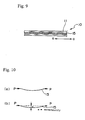
- The details of analysis of the
compound material 10 will now be explained with reference to FIG. 9. - The direction of the
compound material 10 is shown by arrow "a". The unidirectional fibers (carbon fibers, glass fibers and the like) 15 positioned inside a plastic material 11 should be arranged parallel to arrow "a", but as shown in the drawing, thefibers 15 are bent in a wavy manner against the arrow "a" direction. - A state is shown in FIG. 10 where the
compound material 10 including the wavy-deformedfiber 15 receives compressive strength. When the deformed,decentered fiber 15 receives compressive load P from the direction of the fiber, the fiber will oppose to the load up to a predetermined level, but when the load exceeds the limit of the fiber, the fiber will be buckled (refer to FIG. 10 (a)). - As shown by FIG. 10 (b), when further load P is placed, the buckled
fiber 15 will be decentered to eccentricity "a" by even a small load. - As explained, the
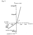
deformed fiber 15 was easily decentered by a small compressive load, and did not exert the expected compressive strength, which was disadvantageous for a structural material. - Moreover, when a decentered fiber exists in the completed structural member, the decentered fiber existing in the resin will be straightened at first when tensile load is provided to the material. After the fiber is straightened, the compound material will show reaction force. The state is shown by a stress/strain diagram (refer to FIG. 11). The relation between the load (compressive stress, tensile stress) and the strain (shrinkage, elongation) is not expressed by a straight line at the initial point 0. In other words, the structural member will not be elongated in proportion to the tensile stress.
- As a result, the stress is concentrated to the fibers having a relatively high straightness, and the fiber to which the stress is concentrated may break, which results in the defection of the material.
- The cause of existence of such decentered fiber is that in the prior art forming method where pressurization and depressurization is repeated intermittently, pressure could not be added continuously during the curing of the resin, and the fine waves of. the fibers included in the material could not be straightened during the forming process.
- The completed material which has gone through the forming process is cooled, and returned to ordinary temperature. At this time, the thermally expanded resin will shrink.
- During cooling time, when thermal shrinkage occurs to the structural material with the reinforcement fibers being elongated linearly, the fibers oppose to the thermal shrinkage of the resin and maintain a linear state. However, when the fibers are not elongated linearly during the heating, the fibers will not show any resistance to the bend accompanied by the shrinkage of the resin.
- For example, the thermal expansion coefficient of an epoxy resin used as the matrix of a structural member is as large as 27 ppm/°C. When the temperature of the product is cooled down from 180 °C to 20 °C, the structural material will shrink by 0.4 %. On the other hand, the thermal expansion coefficient of the included carbon fibers is as small as 0.3 ppm/°C (5 ppm/°C in the case of glass fibers), and the fibers hardly shrink. In other words, during thermal shrinkage, the fibers which are not elongated linearly will be bent even further accompanying the shrinkage of the resin. As a result, as shown in FIG. 9, the fibers acting as the reinforcing member of the structural material are deformed to have continuous wavy bends.
- According to calculation, a thermal shrinkage by 0.4 % will result in the deformation of fiber having a wavelength of approximately 3 mm and an eccentricity rate of 1.6 %, which cannot be ignored.
- The drop in compressive strength of the material caused by the fine wavy deformation of the fiber included in the material as reinforcement member is a problem common to any compound structural material of the prior art. In the studies, such a problem is called micro-buckling, and the method for solving such a problem is inquired.
- The present invention solves the problem by providing a method and device for forming a compound material characterized by the features of
claim 1 and 4 allowing the manufacturing of a compound material in which the fibers included in the compound material as reinforcement member are not deformed to have waviness, but instead, arranged linearly within the material. - In order to solve the above-mentioned problem, the present invention provides a method for forming a compound material comprising a pinching step of pinching and fixing the upstream end and the downstream end of a composite material and providing a tension toward the downstream advancing direction to the downstream end of said composite material, a heating/pressurizing step of heating and pressurizing the pinched and fixed composite material intermittently, and a moving step of releasing the compound material and sending said material to the downstream direction after termination of the heating/pressurizing step and setting the amount of movement of said compound material at the downstream side to be greater than the amount of movement of said compound material at the upstream side.
- In a further aspect of the method, the tension toward the downstream advancing direction provided to the downstream end of the material is added from before the starting of said heating/pressurizing step to after the termination of said heating/pressurizing step. In another aspect of the method, during said moving step, a tension toward the upstream direction is provided to the upstream side of said compound material.
- The device for forming the compound material according to the present invention comprises a pinching means for pinching and fixing the upstream end and the downstream end of a composite material being supplied thereto and further equipped with a tension adding means providing tension toward the downstream direction of movement, and a heating/pressurizing means for heating and pressurizing said composite material being pinched and fixed, wherein a downstream moving means is set so that the amount of said compound material being moved by said downstream moving means is greater than the amount being moved by an upstream moving means, and the tension adding means of the pinching means is started just before said heating/pressurizing means is started.
- Even further, the upstream moving means is equipped with a tension adding means for providing tension toward the upstream direction opposite to the advancing direction, the tension toward the downstream direction of said downstream moving means being set to be greater than the tension provided by said tension adding means of the upstream moving means, so that the amount of movement of the composite material by the downstream moving means is greater than the amount of movement of the material by the upstream moving means. In another aspect of the invention, the tension adding means of the pinching means pinching the downstream end of the material providing tension toward the downstream direction starts to operate when said upstream moving means and said downstream moving means stop operating, and said tension adding means stops operating when said pinching means pinching the upstream end and said pinching means pinching the downstream end stop operating. During all molding steps, the fibers in the material are provided with tension so that they are straightened linearly in the material.
-
- FIG. 1 is an explanatory view showing the whole system of the forming device according to the present invention;
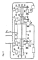
- FIG. 2 is a view showing the structural outline of the forming device according to the present invention;
- FIG. 3 is a timing chart showing the operation of each device;
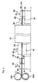
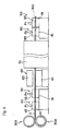
- FIG. 4 is an explanatory view showing the state of operation;
- FIG. 5 is an explanatory view showing the state of operation;
- FIG. 6 is an explanatory view showing the state of operation;
- FIG. 7 is an explanatory view showing the state of operation;
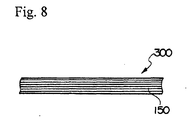
- FIG. 8 is an explanatory view of the compound material formed according to the present invention;
- FIG. 9 is an explanatory view showing the compound material of the prior art;
- FIG. 10 is an explanatory view showing the fibers in the compound material; and
- FIG. 11 is a graph showing the relation between the compression force and the extension of the compound material of the prior art.
-
- The preferred embodiment of the present invention will now be explained with reference to the accompanied drawings.
- FIGS. 1 and 2 are explanatory views showing the whole device for forming the compound material.
- A
composite material 3 formed of a prepreg material is supplied from afirst supply roll 30A and asecond supply roll 30B, and is pinched and supported by an interlockedupstream fixing device 40 and an interlockeddownstream fixing device 90. The suppliedcomposite material 3 is moved by anupstream sending device 50 and adownstream sending device 80 which intermittently send thecomposite material 3 downstream. Thecomposite material 3 is heated and cured by apressurizer 60 and aheat curing furnace 70, and discharged therefrom as a completed product (compound material) 300. - The
upstream fixing device 40 and the downstream fixing.device 90 are interlocked with the movement of thecomposite material 3, and intermittently repeats pinching (supporting) and releasing of thematerial 3. - The
upstream fixing device 40 comprises a fixingunit 41 and a pressurizingunit 43. The pressurizingunit 43 executes the movement (pressurization) toward the fixingunit 41 by apress cylinder 45 which is shown as a move P1 in the direction of the arrow. Thedownstream fixing device 90 comprises a fixingunit 91 and a pressurizingunit 93. The pressurizingunit 93 executes the movement (pressurization) toward the fixingunit 91 by apress cylinder 95 which is shown as a move P7 in the direction of the arrow. Athird tension cylinder 97 is connected to the fixingunit 91, which executes the movement of (provides tension to) thedownstream fixing device 90 toward the downstream direction which is shown as a move P8 in the direction of the arrow. As explained, the curedcompound material 300 which has passed through theheat curing furnace 70 is pinched and released repeatedly, and at the same time, thecompound material 300 is pulled toward the downstream direction when it is being pinched. - The
upstream sending device 50 and the downstream sendingdevice 80 are interlocked to repeatedly pinch and release thecomposite material 3 or thecompound material 300, and moves the material toward the advancing direction (downstream) when the material is being pinched. - The
upstream sending device 50 comprises asend fixer 51 and asend pressurizer 53. Thepressurizer 53 is moved by apress cylinder 55 toward thefixer 51 shown as a move P2 in the direction of the arrow, so as to repeatedly pinch and release thecomposite material 3. Afirst tension cylinder 57 is connected to thesend fixer 51, so that when thecomposite material 3 is pinched and moved downstream, thesend fixer 51 is moved (adding tension) toward the upstream direction shown as a move P3 in the direction of the arrow. - The
downstream sending device 80 is placed downstream from theheat curing furnace 70, and comprises asend fixer 81 and asend pressurizer 83. Thepressurizer 83 is moved (pressurized) by apress cylinder 85 toward thefixer 81 shown as a move P5 in the direction of the arrow, so that it repeatedly pinches and releases thecompound material 300 which has passed through a heating/pressurizing device 60 and theheat curing furnace 70. Asecond tension cylinder 87 is connected to thesend fixer 81, so that when thecompound material 300 is pinched, thesend fixer 81 is moved (adding tension) toward the downstream direction shown as a move P6 in the direction of the arrow. - The piston diameter of the
second tension cylinder 87 is set larger than the piston diameter of thefirst tension cylinder 57 in the present forming device. Therefore, when the same hydraulic pressure is added to the first and the second cylinders, the power of thesecond tension cylinder 87 pulling the downstream sendingdevice 80 toward the downstream direction by movement P8 is larger than the power of thefirst tension cylinder 57 pulling the upstream sendingdevice 50 toward the upstream direction by the movement P3, and thecompound material 300 will be moved toward the downstream direction while receiving tensile power from both ends. - The pressurizing
device 60 comprises a fixedpressurizer 61 and apressurizer 63. Thepressurizer 63 performs movement (pressurization) toward the fixedpressurizer 61 shown as movement P4 in the direction of the arrow by a press cylinder not shown, and intermittently repeats the pinching and releasing of thecomposite material 3. - When the
composite material 3 is not moved, thematerial 3 is pinched by the fixedpressurizer 61 and thepressurizer 63, where it is heated and pressurized. Next, when thepressurizer 63 is moved in a direction opposite to the arrow thereby releasing thecomposite material 3, the sendingdevices device 60 is sent to theheat curing furnace 70, where it is completely cured. The material is then moved by the sendingdevice 80 as a completedcompound material 300, and then discharged. - The discharged
compound material 300 is formed so thatfibers 150 are arranged in straight lines, as shown in FIG. 8. - Next, the relation between the operation of each device and the movement of the compound material is explained with reference to the timing chart shown in FIG. 3.
- Until time T1, except for the upstream sending
device 50 and the downstream sendingdevice 80, all of theupstream fixing device 40, the pressurizingdevice 60 and thedownstream fixing device 90 hold (pinch) thecomposite material 3 orcompound material 300, while heating and pressurizing the same. - At time T1, the pressurization by the
pressurizer 63 of the heating/pressurizing device 60 is released. - At time T2, the
pressurizer 43 of the fixingdevice 40 is released, and thepressurizer 93 of the fixingdevice 90 is released, thereby releasing thecomposite material 3. Then, the upstream sendingdevice 50 and the downstream sendingdevice 80 are started, which pinch thecomposite material 3 orcompound material 300. - When the pressure from each
pressurizers devices device 50 is started. At the same time, the second tension cylinder 87 (movement P6) is started. Since the relation between the moving forces of each cylinder is set as movement P3 < movement P6, the power of the movement P6 of thesecond tension cylinder 87 of thesecond sending device 80 is greater than the power of the movement P3 of thefirst tension cylinder 57 trying to pull back thecomposite material 3 from moving downstream. Therefore, the upstream sendingdevice 50 will not move while movement power P3 is resisting, but when the movement could no longer be resisted, the first sendingdevice 50 and thesecond sending device 80 move downstream while pinching thecomposite material 3 orcompound material 300. When the movement of the upstream sendingdevice 50 is expressed as movement length L1, and the movement of the downstream sendingdevice 80 is expressed as movement length L2, the relation between the two lengths is shown as L1 < L2. - At this time, the
composite material 3 or thecompound material 300 receives tension toward both upstream and downstream directions. - When the movement is terminated at time T5, the
pressurizer 43 of theupstream fixing device 40 and thepressurizer 93 of thedownstream fixing device 90 are started, and movement P1 and movement P7 are performed. Thereby, thecomposite material 3 orcompound material 300 is pinched. - At time T6, the
pressurizer 53 of the upstream sendingdevice 50 and thepressurizer 83 of the downstream sendingdevice 80 are depressurized, and the pinching performed by the upstream sending device and the downstream sending device are released. - Further, at time T7, the
first tension cylinder 57 and thesecond tension cylinder 87 are stopped, and thethird tension cylinder 97 is operated (movement P8). - When hydraulic pressure is not provided to the
first tension cylinder 57 and thesecond tension cylinder 87, the pressure of the press cylinder drops, and by the reset of the spring inside the cylinder, the upstream sendingdevice 50 and the downstream sendingdevice 80 return to their initial positions. - Simultaneously as the upstream sending
device 50 and the downstream sendingdevice 80 are returned to their initial positions, the third tension cylinder is started. Thereby, thethird tension cylinder 97 pulls thecompound material 300 downstream by a tension of movement P8. - As explained, while the upstream sending
device 50 and the downstream sendingdevice 80 release thecomposite material 3, the upstream side of thecomposite material 3 is pinched and fixed by theupstream fixing device 40, and at the same time, the downstream side of thecompound material 300 is pulled toward the advancing direction by the tension of movement P8 by thedownstream fixing device 90. - As explained above, the
composite material 3 and thecompound material 300 are provided with a pressurizing force or a tensile force during all steps including the heating/pressurizing step (from time T8 to time T1), the depressurizing step (from time T1 to time T3), the moving step (from time T3 to time T5), the pinching step (from time T5 to time T7), and the resetting step (from time T7 to time T8). - The provided tension is controlled by adjusting the tension cylinder pressures of the
first tension cylinder 57, thesecond tension cylinder 87 and thethird tension cylinder 97 according to the size, the cross-sectional area and the like of thecomposite material 3. - The
compound material 300 formed as above provides preferred compression and tensile strength, withfibers 150 included as reinforcing material arranged in straight lines. - It is discovered through experiment that by providing approximately 500 kg of tension per 1 square cm of the cross-sectional area of the compound material, the straightness of the carbon fibers arranged within the compound material is improved, and the wavy deformation of the fibers is greatly reduced.
- As explained, the method of forming the compound material according to the present invention applies providing tension to the fibers continuously throughout the whole forming steps of the method including the pressurizing cycle, the moving cycle, the depressurizing cycle and the like, while the forming step is proceeding intermittently. In other words, the forming device is formed to include a third tension structure (means) for providing tension to the pressurizing cycle and a first and a second tension structure (means) for providing tension to the moving cycle, so that the structures cooperate to provide tension to the fibers throughout the pressurizing cycle and the moving cycle.
- The resin heated and pressurized as above will be melted, cured, and cooled. By providing tension to the fibers consistently, the straightness of the fibers is improved, and the buckling of the fibers accompanying the thermal contraction is prevented. Thereby, a compound material which satisfies a preferable strength is formed.
- The method and device for forming the compound material according to the present invention provides tension to the fibers in the material continuously during all continuous forming steps, so that the fibers inside the formed material are straightened linearly. As a result, the compound material manufactured according to the present invention provides high buckle strength when receiving compression load, has a load/strain curve having straightness, and provides a high tensile strength when receiving tensile load, without any stress concentrating on one portion of the fibers.
Claims (6)
- A method for forming a compound material by intermittently heating and pressurizing a composite material reinforced by fibers, said method comprising:wherein during said pinching step, a tension toward the downstream advancing direction is provided to the downstream end of said composite material, and during said moving step, the amount of movement of said compound material at the downstream side is set to be greater than the amount of movement of said compound material at the upstream side, thereby straightening said fibers in the compound material linearly.a pinching.step of pinching and fixing the upstream end and the downstream end of the composite material;a heating/pressurizing step of heating and pressurizing the pinched and fixed composite material intermittently; anda moving step of releasing the compound material and sending said material to the downstream direction after termination of the heating/pressurizing step;
- A method for forming a compound material according to claim 1, wherein the tension toward the downstream advancing direction provided to the downstream end of the material is added from before the starting of said heating/pressurizing step to after the termination of said heating/pressurizing step.
- A method for forming a compound material according to claim 1, wherein during said moving step, a tension toward the upstream direction is provided to the upstream side of said compound material.
- A device for forming a compound material by intermittently heating and pressurizing a composite material reinforced by fibers, said device comprising:characterized in that said moving means comprises a downstream moving means (80) positioned downstream to said heating/pressurizing means (60), said downstream moving means (80) being set so that the amount of said compound material being moved by said downstream moving means is greater than the amount being moved by said upstream moving means, and said pinching means (90) pinching the downstream end of said compound material is equipped with a tension adding means (97) providing tension toward the downstream advancing direction, said tension adding means of said pinching means being set to start operation just before said heating/pressurizing means (60) is started.a pinching means (40,90) for pinching and fixing the upstream end and the downstream end of a composite material (3) being supplied thereto;a heating/pressurizing means (60) for heating and pressurizing said composite material being pinched and fixed anda moving means (50,80) for sending the compound material released from said pinching means toward the downstream direction;said moving means comprising an upstream moving means (50) positioned upstream to said heating/pressurizing device (60),
- A device for forming a compound material according to claim 4, characterized in that said upstream moving means (50) is equipped with a tension adding means (57) for providing tension toward the upward direction opposite to the advancing direction, the tension towards the downstream direction of said downstream moving means being set to be greater than the tension provided by said tension adding means (57) of the upstream moving means (50), so that the amount of movement of the composite material by the downstream moving means is greater that the amount of movement of the material by the upstream moving means.
- A device for forming a compound material according to claim 4, characterized in that the tension adding means (97) of the pinching means (90) pinching the downstream end of the material and providing tension toward the downstream direction starts to operate when said upstream moving means (50) and said downstream moving means (80) stop operating, and said tension adding means (97) stops operating when said pinching means (40) pinching the upstream end and said pinching means (90) pinching the downstream end stop operating.
Applications Claiming Priority (2)
| Application Number | Priority Date | Filing Date | Title |
|---|---|---|---|
| JP11082053A JP3012847B1 (en) | 1999-03-25 | 1999-03-25 | Composite material molding method and apparatus |
| JP8205399 | 1999-03-25 |
Publications (2)
| Publication Number | Publication Date |
|---|---|
| EP1040901A1 EP1040901A1 (en) | 2000-10-04 |
| EP1040901B1 true EP1040901B1 (en) | 2002-09-18 |
Family
ID=13763784
Family Applications (1)
| Application Number | Title | Priority Date | Filing Date |
|---|---|---|---|
| EP00105122A Expired - Lifetime EP1040901B1 (en) | 1999-03-25 | 2000-03-10 | Method and device for forming a compound material |
Country Status (5)
| Country | Link |
|---|---|
| US (1) | US6569371B1 (en) |
| EP (1) | EP1040901B1 (en) |
| JP (1) | JP3012847B1 (en) |
| DE (1) | DE60000465T2 (en) |
| ES (1) | ES2182744T3 (en) |
Families Citing this family (16)
| Publication number | Priority date | Publication date | Assignee | Title |
|---|---|---|---|---|
| JP3782072B2 (en) * | 2003-05-30 | 2006-06-07 | 川崎重工業株式会社 | Method and apparatus for molding composite mold |
| JP4952056B2 (en) * | 2005-05-23 | 2012-06-13 | 東レ株式会社 | Preform manufacturing method and preform manufacturing apparatus |
| JP5116282B2 (en) | 2006-10-31 | 2013-01-09 | 株式会社ジャムコ | Continuous production method for structural members |
| DE102007018052A1 (en) * | 2007-04-17 | 2008-10-23 | Airbus Deutschland Gmbh | Pultrusion process for producing an endless profile |
| GB0712552D0 (en) * | 2007-06-29 | 2007-08-08 | Airbus Uk Ltd | Elongate composite structural members and improvements therein |
| GB0712553D0 (en) * | 2007-06-29 | 2007-08-08 | Airbus Uk Ltd | Composite panel stiffener |
| GB0712549D0 (en) * | 2007-06-29 | 2007-08-08 | Airbus Uk Ltd | Improvements in elongate composite structural members |
| GB0813161D0 (en) | 2008-07-18 | 2008-08-27 | Airbus Uk Ltd | Ramped stiffener and apparatus and method for forming the same |
| GB0813146D0 (en) * | 2008-07-18 | 2008-08-27 | Airbus Uk Ltd | Ramped stiffener and apparatus and method for forming the same |
| JP5805456B2 (en) * | 2011-08-04 | 2015-11-04 | 株式会社ジャムコ | Manufacturing method of composite material mold for composite material long member |
| DE102012018429A1 (en) * | 2012-06-20 | 2013-12-24 | Thomas Gmbh + Co. Technik + Innovation Kg | Method and device for producing a hollow plastic article having at least one transverse reinforcement |
| KR101360177B1 (en) | 2013-03-28 | 2014-02-11 | 주식회사 티에프티 | Pullout molding apparatus and method of incombustible fiberglass reinforced plastic |
| JP6695046B2 (en) * | 2015-09-25 | 2020-05-20 | パナソニックIpマネジメント株式会社 | Prepreg, metal-clad laminate, wiring board, and method for measuring thermal stress of wiring board material |
| JP2021183740A (en) * | 2020-05-22 | 2021-12-02 | セイコーエプソン株式会社 | Fiber structure manufacturing device, fiber structure manufacturing method, and fiber structure |
| KR102408326B1 (en) * | 2021-02-09 | 2022-06-14 | 주식회사 신성소재 | Pultrusion apparatus |
| CN116118235B (en) * | 2023-04-04 | 2023-06-16 | 江苏沃莱新材料有限公司 | Section bar preparation and conveying equipment |
Family Cites Families (9)
| Publication number | Priority date | Publication date | Assignee | Title |
|---|---|---|---|---|
| JPH0618730B2 (en) | 1987-06-27 | 1994-03-16 | 株式会社ジャムコ | Molding method for plastic composites |
| JPH01310936A (en) | 1988-06-08 | 1989-12-15 | Nippon Steel Chem Co Ltd | Preparation of thermoplastic resin sheet |
| JPH085137B2 (en) | 1988-07-28 | 1996-01-24 | 東レ株式会社 | Fiber-reinforced plastic pultrusion method |
| JPH0618736B2 (en) | 1988-10-08 | 1994-03-16 | 株式会社ジャムコ | Forming method and forming apparatus for prepreg material |
| US5132070A (en) * | 1990-08-17 | 1992-07-21 | Paul Marlene L | Process for the manufacture of composite parts |
| US5096645A (en) * | 1990-10-09 | 1992-03-17 | Plastigage Corporation | Method of forming reinforced thermoplastic members |
| US5721036A (en) * | 1993-03-24 | 1998-02-24 | Tingley; Daniel A. | Aligned fiber reinforcement panel and method for making the same for use in structural wood members |
| US5695848A (en) * | 1994-12-21 | 1997-12-09 | Nicofibers, Inc. | Panel formed from molded fiberglass strands |
| AUPN547595A0 (en) * | 1995-09-15 | 1995-10-12 | Uponor B.V. | Biaxial stretching of plastic tubes |
-
1999
- 1999-03-25 JP JP11082053A patent/JP3012847B1/en not_active Expired - Lifetime
-
2000
- 2000-03-10 ES ES00105122T patent/ES2182744T3/en not_active Expired - Lifetime
- 2000-03-10 DE DE60000465T patent/DE60000465T2/en not_active Expired - Lifetime
- 2000-03-10 EP EP00105122A patent/EP1040901B1/en not_active Expired - Lifetime
- 2000-03-23 US US09/533,977 patent/US6569371B1/en not_active Expired - Lifetime
Also Published As
| Publication number | Publication date |
|---|---|
| JP2000271949A (en) | 2000-10-03 |
| DE60000465T2 (en) | 2003-08-07 |
| JP3012847B1 (en) | 2000-02-28 |
| DE60000465D1 (en) | 2002-10-24 |
| ES2182744T3 (en) | 2003-03-16 |
| EP1040901A1 (en) | 2000-10-04 |
| US6569371B1 (en) | 2003-05-27 |
Similar Documents
| Publication | Publication Date | Title |
|---|---|---|
| EP1040901B1 (en) | Method and device for forming a compound material | |
| AU688203B2 (en) | Pultrusion method and apparatus | |
| US7186361B2 (en) | Method and apparatus for continuous molding of fiber reinforced plastic member with curvature | |
| US20080099131A1 (en) | Method for continuously forming structural member | |
| US4720255A (en) | Apparatus for planar forming of zero degree composite tape | |
| CN111619188B (en) | Method of making shaped composite laminate stiffeners | |
| JPH0618730B2 (en) | Molding method for plastic composites | |
| US20100167039A1 (en) | Composite laminated structure reinforced by inserting pins, a method and a apparatus for making the same and a method for making the apparatus | |
| EP1894706A1 (en) | Method for continuously preforming composite material in uncured state | |
| KR20000036011A (en) | Reinforced composite product and apparatus and method for producing same | |
| US5681513A (en) | Method for fabricating composite structures using continuous press forming | |
| EP3444106B1 (en) | Die-based composite fabrication | |
| EP3632643B1 (en) | Method for producing composite material component and device for producing composite material component | |
| CN111206722A (en) | Fiber composite material | |
| JP6310578B2 (en) | Pre-preg capable of deep drawing and manufacturing method thereof | |
| JP3402481B2 (en) | Pre-preg material molding equipment | |
| Muzzy et al. | Thermoforming of high performance thermoplastic composites | |
| WO1996016792A1 (en) | Inhibiting resin expulsion during molding of elongate fiber reinforced products | |
| EP3976360B1 (en) | Device and method for manufacturing a composite component | |
| WO2020195115A1 (en) | Prepreg molding method | |
| EP4023422A1 (en) | Method for manufacturing structure and structure | |
| EP2674285A1 (en) | Method and conforming tool for manufacturing pieces of composite material with a high dimensional quality |
Legal Events
| Date | Code | Title | Description |
|---|---|---|---|
| PUAI | Public reference made under article 153(3) epc to a published international application that has entered the european phase |
Free format text: ORIGINAL CODE: 0009012 |
|
| AK | Designated contracting states |
Kind code of ref document: A1 Designated state(s): DE ES FR GB |
|
| AX | Request for extension of the european patent |
Free format text: AL;LT;LV;MK;RO;SI |
|
| 16A | New documents despatched to applicant after publication of the search report |
Effective date: 20000919 |
|
| 17P | Request for examination filed |
Effective date: 20000907 |
|
| 17Q | First examination report despatched |
Effective date: 20010212 |
|
| AKX | Designation fees paid |
Free format text: DE ES FR GB |
|
| GRAG | Despatch of communication of intention to grant |
Free format text: ORIGINAL CODE: EPIDOS AGRA |
|
| GRAG | Despatch of communication of intention to grant |
Free format text: ORIGINAL CODE: EPIDOS AGRA |
|
| GRAH | Despatch of communication of intention to grant a patent |
Free format text: ORIGINAL CODE: EPIDOS IGRA |
|
| GRAH | Despatch of communication of intention to grant a patent |
Free format text: ORIGINAL CODE: EPIDOS IGRA |
|
| GRAA | (expected) grant |
Free format text: ORIGINAL CODE: 0009210 |
|
| AK | Designated contracting states |
Kind code of ref document: B1 Designated state(s): DE ES FR GB |
|
| REG | Reference to a national code |
Ref country code: GB Ref legal event code: FG4D |
|
| REF | Corresponds to: |
Ref document number: 60000465 Country of ref document: DE Date of ref document: 20021024 |
|
| ET | Fr: translation filed | ||
| REG | Reference to a national code |
Ref country code: ES Ref legal event code: FG2A Ref document number: 2182744 Country of ref document: ES Kind code of ref document: T3 |
|
| PLBE | No opposition filed within time limit |
Free format text: ORIGINAL CODE: 0009261 |
|
| STAA | Information on the status of an ep patent application or granted ep patent |
Free format text: STATUS: NO OPPOSITION FILED WITHIN TIME LIMIT |
|
| 26N | No opposition filed |
Effective date: 20030619 |
|
| REG | Reference to a national code |
Ref country code: FR Ref legal event code: PLFP Year of fee payment: 17 |
|
| REG | Reference to a national code |
Ref country code: FR Ref legal event code: PLFP Year of fee payment: 18 |
|
| REG | Reference to a national code |
Ref country code: FR Ref legal event code: PLFP Year of fee payment: 19 |
|
| PGFP | Annual fee paid to national office [announced via postgrant information from national office to epo] |
Ref country code: GB Payment date: 20190306 Year of fee payment: 20 Ref country code: DE Payment date: 20190226 Year of fee payment: 20 |
|
| PGFP | Annual fee paid to national office [announced via postgrant information from national office to epo] |
Ref country code: FR Payment date: 20190213 Year of fee payment: 20 |
|
| PGFP | Annual fee paid to national office [announced via postgrant information from national office to epo] |
Ref country code: ES Payment date: 20190402 Year of fee payment: 20 |
|
| REG | Reference to a national code |
Ref country code: DE Ref legal event code: R071 Ref document number: 60000465 Country of ref document: DE |
|
| REG | Reference to a national code |
Ref country code: GB Ref legal event code: PE20 Expiry date: 20200309 |
|
| PG25 | Lapsed in a contracting state [announced via postgrant information from national office to epo] |
Ref country code: GB Free format text: LAPSE BECAUSE OF EXPIRATION OF PROTECTION Effective date: 20200309 |
|
| REG | Reference to a national code |
Ref country code: ES Ref legal event code: FD2A Effective date: 20200805 |
|
| PG25 | Lapsed in a contracting state [announced via postgrant information from national office to epo] |
Ref country code: ES Free format text: LAPSE BECAUSE OF EXPIRATION OF PROTECTION Effective date: 20200311 |