EP1044665A2 - Blade-shaped stem of a hip joint prosthesis for anchoring in the femur - Google Patents
Blade-shaped stem of a hip joint prosthesis for anchoring in the femur Download PDFInfo
- Publication number
- EP1044665A2 EP1044665A2 EP00107892A EP00107892A EP1044665A2 EP 1044665 A2 EP1044665 A2 EP 1044665A2 EP 00107892 A EP00107892 A EP 00107892A EP 00107892 A EP00107892 A EP 00107892A EP 1044665 A2 EP1044665 A2 EP 1044665A2
- Authority
- EP
- European Patent Office
- Prior art keywords
- anchoring section
- femur
- shaft according
- anchoring
- shaft
- Prior art date
- Legal status (The legal status is an assumption and is not a legal conclusion. Google has not performed a legal analysis and makes no representation as to the accuracy of the status listed.)
- Granted
Links
Images


Classifications
-
- A—HUMAN NECESSITIES
- A61—MEDICAL OR VETERINARY SCIENCE; HYGIENE
- A61F—FILTERS IMPLANTABLE INTO BLOOD VESSELS; PROSTHESES; DEVICES PROVIDING PATENCY TO, OR PREVENTING COLLAPSING OF, TUBULAR STRUCTURES OF THE BODY, e.g. STENTS; ORTHOPAEDIC, NURSING OR CONTRACEPTIVE DEVICES; FOMENTATION; TREATMENT OR PROTECTION OF EYES OR EARS; BANDAGES, DRESSINGS OR ABSORBENT PADS; FIRST-AID KITS
- A61F2/00—Filters implantable into blood vessels; Prostheses, i.e. artificial substitutes or replacements for parts of the body; Appliances for connecting them with the body; Devices providing patency to, or preventing collapsing of, tubular structures of the body, e.g. stents
- A61F2/02—Prostheses implantable into the body
- A61F2/30—Joints
- A61F2/32—Joints for the hip
- A61F2/36—Femoral heads ; Femoral endoprostheses
- A61F2/3662—Femoral shafts
-
- A—HUMAN NECESSITIES
- A61—MEDICAL OR VETERINARY SCIENCE; HYGIENE
- A61F—FILTERS IMPLANTABLE INTO BLOOD VESSELS; PROSTHESES; DEVICES PROVIDING PATENCY TO, OR PREVENTING COLLAPSING OF, TUBULAR STRUCTURES OF THE BODY, e.g. STENTS; ORTHOPAEDIC, NURSING OR CONTRACEPTIVE DEVICES; FOMENTATION; TREATMENT OR PROTECTION OF EYES OR EARS; BANDAGES, DRESSINGS OR ABSORBENT PADS; FIRST-AID KITS
- A61F2/00—Filters implantable into blood vessels; Prostheses, i.e. artificial substitutes or replacements for parts of the body; Appliances for connecting them with the body; Devices providing patency to, or preventing collapsing of, tubular structures of the body, e.g. stents
- A61F2/02—Prostheses implantable into the body
- A61F2/30—Joints
- A61F2002/30001—Additional features of subject-matter classified in A61F2/28, A61F2/30 and subgroups thereof
- A61F2002/30316—The prosthesis having different structural features at different locations within the same prosthesis; Connections between prosthetic parts; Special structural features of bone or joint prostheses not otherwise provided for
- A61F2002/30535—Special structural features of bone or joint prostheses not otherwise provided for
-
- A—HUMAN NECESSITIES
- A61—MEDICAL OR VETERINARY SCIENCE; HYGIENE
- A61F—FILTERS IMPLANTABLE INTO BLOOD VESSELS; PROSTHESES; DEVICES PROVIDING PATENCY TO, OR PREVENTING COLLAPSING OF, TUBULAR STRUCTURES OF THE BODY, e.g. STENTS; ORTHOPAEDIC, NURSING OR CONTRACEPTIVE DEVICES; FOMENTATION; TREATMENT OR PROTECTION OF EYES OR EARS; BANDAGES, DRESSINGS OR ABSORBENT PADS; FIRST-AID KITS
- A61F2250/00—Special features of prostheses classified in groups A61F2/00 - A61F2/26 or A61F2/82 or A61F9/00 or A61F11/00 or subgroups thereof
- A61F2250/0058—Additional features; Implant or prostheses properties not otherwise provided for
Definitions
- the invention relates to a sheet-like shaft Hip prosthesis for anchoring in the femur with a Femur anchoring section and a prosthetic neck.
- EP 0 427 902 B1 proposes a section of the Execute the shaft with contact surfaces provided with saw teeth. This should allow the shaft to grow into the Bone substance can be improved.
- the present invention is based on the object Femur anchoring section of a leaf-like shaft so too shape that the tissue growing on the prosthesis if possible consists largely of cancellous bone tissue, so that a firm hold of the shaft in the femur is permanently guaranteed.
- the revascularization of the bone tissue additionally promoted, namely under Maintaining the necessary stability or strength of the Shank on the one hand, but with enlargement of the space between the shaft and the surgical cavity on the other hand with the result of increased training of new cancellous bone.
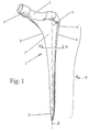
- Fig. 1 shows a perspective view of a leaf-like Shaft 1 of a hip prosthesis for anchoring in the femur.
- the embodiment shown comprises one of one distal end 5 from widening conically on all sides Anchoring section 1a, ... 1i (see Fig. 2 to 10), the in the proximal area on the medial side into a steady curved arc 8 passes.
- This arch 8 sits in one Denture neck 2 continued; there is a conical taper on them Pin 3 placed on a spherical joint head records.
- the prosthesis neck axis intersects the (in Fig. 1 not shown) longitudinal central axis of the shaft or anchoring section 1a ... 1i at an angle that in essentially the angle between the femoral neck and the Femur axis corresponds to a natural hip joint.
- a trochanter wing 4 is formed laterally in the proximal region of the shaft 1 and is laterally delimited by a side surface 9.
- the transition between the lateral surface on the one hand and the posterior or anterior surface on the other hand is defined by an oblique edge 6 which extends from distal to proximal in the region of the trochanter wing 4.
- the Blade "of the shaft 1 is defined in the proximal region and is identified by the reference number 7.
- 2 - 10 are different cross sections or Profile shapes of anchoring sections 1a ... 1i des Shaft 1 shown.
- the anchoring section 1 a is an oblique cross profile trained, with the legs anterior and posterior each have a V-shaped groove 11a, 11b with an angle greater than 90 ° and laterally and medially with a V-shaped groove 12a, 12b form an angle of less than 90 °.
- This Profile includes rectangular recesses 13a, 13b on the posterior and anterior side.
- Fig. 4 shows a further variant in which the anchoring section 1c of the shaft 1 is a double H profile or double comb profile is with the formation of rectangular longitudinal grooves 14a, 14b, 14c, 14d on the posterior and anterior side of the Anchoring section.
- Fig. 5 is the anchoring section 1d of the shaft 1 in the rough cross-sectional shape rectangular, with hollow facets formed on the four edges.
- FIGS. 6 and 7 show one Anchoring section 1e or 1f in the form of a rectangular hollow profile, 6 in the embodiment according to FIG Cross section of the cavity 15 is rectangular, while at 7 the cross section of the cavity 16 is elliptical. These two variants are characterized by a particularly high stability of the anchoring section on the one hand and light weight on the other.
- the variant according to FIG. 8 shows an anchoring section 1g, which is defined by a rectangular notch profile. Are there posterior and anterior two spaced apart Longitudinal notches 17a, 17b and 17c, 17d formed. It is about each by V-notches. Lateral and medial are one Longitudinal notch 18a, 18b provided, also V-shaped Notches or longitudinal grooves.
- the edges bounding the outline of the anchoring section 1g can, just as in the case of Embodiment according to FIGS. 6 and 7 each flat or Have hollow facets corresponding to FIG. 5.
- the rectangular cavity 15 still be divided by one in the longitudinal direction of the shaft extending web or cross web.
- the embodiment according to FIG. 8 can be like the one according to FIG 5 be designed as a hollow profile with a Longitudinal cavity extending cavity, the cross section is circular or oval or elliptical.
- FIG. 9 1h differs from that shown in Figures 2-8 Executions by a trapezoidal cross-sectional shape, the here symmetrical with two equally long side edges a, those in cross section the anterior or posterior Limit sides and two different lengths shorter side edges b, c, of which the shorter medial and the longer that comes to lie laterally is shown.
- This symmetrical trapezoidal shape is currently considered the preferred viewed, but are also generally asymmetrical trapezoidal Prosthetic socket cross-sections are possible.
- FIGS. 2-8 modifications of the cross-sectional shapes shown in FIGS. 2-8 (which are, as it were, inscribed in a rectangle in these figures) can also be carried out, for example an asymmetrical diagonal cross H "with a longer and a shorter leg, an embodiment similar to FIG. 4 with three legs of different lengths, an embodiment corresponding to the embodiment according to FIG. 5 with hollow facets in the edge regions of a trapezoidal cross section or various hollow profiles with a trapezoidal outer shape.
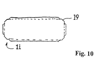
- Fig. 10 is to show another special Execution of the anchoring section of the invention
- Shaft prosthesis shown a cross-sectional shape, which in turn is based on the basic shape of a rectangle and on all edges has stepped chamfer areas 19.
- This embodiment is based on the idea that with a prosthesis socket - at least in the proximal area - a predetermined excess compared to the dimensions of the prepared femoral cavity (ie compared to the Rasp size ”) is advantageous in that it increases the surface pressure compared to the surrounding bone tissue and thereby brings about a certain amount of bone compression.
- the excess is, also in view of the usual forging accuracy, about 1-3%, based on that as well Rasp size to be understood in the medullary canal.
- a stepped edge shape shown in Fig. 10 The resulting re-milling has proven to be relatively easy to implement and proven to be effective in an advantageous manner; basically other fine structures in the edge area are also possible, with which the dimensional accuracy of the edges (more precisely: the Chamfer) is reconciled with an excess of remaining side and end faces - for example Rounding or additional, compared to the actual chamfer inclined chamfers.
Abstract
Description
Die Erfindung betrifft einen blattartigen Schaft einer Hüftgelenkprothese für die Verankerung im Femur mit einem Femur-Verankerungsabschnitt und einem Prothesenhals.The invention relates to a sheet-like shaft Hip prosthesis for anchoring in the femur with a Femur anchoring section and a prosthetic neck.
Derartige Profilschäfte sind allgemein bekannt. Es wird diesbezüglich nur beispielhaft verwiesen auf die EP 0 427 902 B1 oder EP 0 244 610 B1 oder US 4 908 035.Such profile shafts are generally known. It will be in this regard referred to EP 0 427 902 B1 only by way of example or EP 0 244 610 B1 or US 4 908 035.
In der Regel sind die Flächen des Verankerungsabschnittes eines Schaftes der hier fraglichen Art glatt ausgebildet. In der EP 0 427 902 B1 ist vorgeschlagen, einen Abschnitt des Schaftes mit mit Sägezähnen versehenen Anlageflächen auszuführen. Dadurch soll ein Einwachsen des Schaftes in die Knochensubstanz verbessert werden.As a rule, the surfaces of the anchoring section a shaft of the type in question here smoothly formed. EP 0 427 902 B1 proposes a section of the Execute the shaft with contact surfaces provided with saw teeth. This should allow the shaft to grow into the Bone substance can be improved.
Aus der CH-A 642 252 ist es bekannt, die nach anterior und posterior weisenden Blattseiten eines Schaftes mit rillenartigen Vertiefungen zu versehen. In diese wächst Knochengewebe jedoch nur schlecht ein. Das diese Vertiefungen ausfüllende Gewebe ist im allgemeinen ein nur wenig stabiles Bindegewebe. From CH-A 642 252 it is known that the anterior and posteriorly facing leaf sides of a shaft with groove-like To provide recesses. Bone tissue grows in this however, only a bad one. The one that fills these recesses Tissue is generally a poorly stable connective tissue.
Der vorliegenden Erfindung liegt die Aufgabe zugrunde, den Femur-Verankerungsabschnitt eines blattartigen Schaftes so zu gestalten, daß das an die Prothese anwachsende Gewebe möglichst weitgehend aus spongiösem Knochengewebe besteht, so daß ein fester Halt des Schaftes im Femur dauerhaft gewährleistet ist.The present invention is based on the object Femur anchoring section of a leaf-like shaft so too shape that the tissue growing on the prosthesis if possible consists largely of cancellous bone tissue, so that a firm hold of the shaft in the femur is permanently guaranteed.
Diese Aufgabe wird durch einen blattartigen Schaft mit den
Merkmalen von Anspruch 1 gelöst.This task is carried out by a leaf-like shaft with the
Features of
Die Erfindung schließt den grundlegenden Gedanken ein, daß der
Femur-Verankerungsabschnitt des Schaftes im Querschnitt im
wesentlichen viereckig, also in vereinfachender (die Verjüngung
zum Ende hin außer Acht lassender) Bezeichnung als ![]()
- Schrägkreuzprofil
- H-Profil
- Doppel-H- bzw. -Kammprofil
- Rechteck-Hohlprofil
- Rechteck-Facettenprofil
- Rechteck-Kerbprofil
- annähernd trapezförmiges Profil (mit oder ohne Ausnehmungen an den Seiten oder im Innern)
- oder dergleichen.
- Oblique cross profile
- H profile
- Double H or comb profile
- Rectangular hollow profile
- Rectangular facet profile
- Rectangular notch profile
- approximately trapezoidal profile (with or without recesses on the sides or inside)
- or similar.
Bei diesen Profilen hat sich mehr oder weniger ausgeprägt gezeigt, daß sich in dem zwischen Verankerungsabschnitt des Schaftes einerseits und Operationshohlraum andererseits definierten Zwischenraum spongioses Knochengewebe bildet und damit eine Revaskularisierung des Knochen stattfindet. Die erfindungsgemäßen Alternativen haben den Vorteil, daß sie im wesentlichen vier Umrißkanten bilden, die an den Ecken eines sich senkrecht zur Schaftmittelachse erstreckenden Rechtecks oder Trapezes liegen. Diese Grundform eines Schaftes hat sich in der Praxis als besonders vorteilhaft erwiesen für die Revaskularisierung des Knochengewebes.These profiles have more or less developed shown that in the anchoring section of the Shank on the one hand and surgical cavity on the other defines defined space of cancellous bone tissue and so that a revascularization of the bone takes place. The Alternatives according to the invention have the advantage that they form essentially four outline edges, which at the corners of a Rectangle extending perpendicular to the shaft center axis or trapezes. This basic form of a shaft has proven in practice to be particularly advantageous for the Revascularization of the bone tissue.
Weiterhin hat sich gezeigt, daß eine vorbestimmte Übermaßigkeit
der Seitenflächen des Schaftes gegenüber dem Raspelmaß
(
Mit der erfindungsgemäßen Weiterbildung wird die Revaskularisierung des Knochengewebes zusätzlich gefördert, und zwar unter Beibehaltung der notwendigen Stabilität bzw. Festigkeit des Schaftes einerseits, jedoch unter Vergrößerung des Zwischenraumes zwischen Schaft und Operationshohlraum andererseits mit dem Ergebnis einer erhöhten Ausbildung neuer Spongiosa.With the development according to the invention, the revascularization of the bone tissue additionally promoted, namely under Maintaining the necessary stability or strength of the Shank on the one hand, but with enlargement of the space between the shaft and the surgical cavity on the other hand with the result of increased training of new cancellous bone.
Vorteilhafte Details des erfindungsgemäßen Prothesenschaftes sind in den Unteransprüchen bzw. nachfolgend bei der Erläuterung von Ausführungsbeispielen anhand der beigefügten Zeichnungen näher erläutert. Es zeigen
- Fig. 1
- eine perspektivische Ansicht eines blattartigen Schaftes, dessen Femur-Verankerungsabschnitt erfindungsgemäß weitergebildet wird;
- Fig. 2 - 9
- verschiedene Querschnitte des Verankerungsabschnittes des Schaftes gemäß Fig. 1 längs der Linie A-A in Fig. 1, und
- Fig. 10
- eine weitere bevorzugte Ausführung in Querschnittsdarstellung.
- Fig. 1
- a perspective view of a leaf-like shaft, the femur anchoring section is further developed according to the invention;
- Fig. 2-9
- different cross sections of the anchoring portion of the shaft according to FIG. 1 along the line AA in Fig. 1, and
- Fig. 10
- a further preferred embodiment in cross-sectional representation.
Fig. 1 zeigt in perspektivischer Ansicht einen blattartigen
Schaft 1 einer Hüftgelenkprothese für die Verankerung im Femur.
Das gezeigte Ausführungsbeispiel umfaßt einen sich von einem
distalen Ende 5 aus nach proximal allseitig konisch erweiternden
Verankerungsabschnitt 1a, ... 1i (siehe Fig. 2 bis 10), der
im proximalen Bereich an der medialen Seite in einen stetig
gekrümmten Bogen 8 übergeht. Dieser Bogen 8 setzt sich in einem
Prothesenhals 2 fort; auf diesen ist ein sich konisch verjüngender
Zapfen 3 aufgesetzt, der einen kugelförmigen Gelenkkopf
aufnimmt. Die Prothesenhalsachse schneidet die (in Fig. 1
nicht dargestellte) Längsmittelachse des Schaftes bzw. Verankerungsabschnittes
1a ... 1i unter einem Winkel, der im
wesentlichen dem Winkel zwischen dem Schenkelhals und der
Femurachse eines natürlichen Hüftgelenkes entspricht.Fig. 1 shows a perspective view of a leaf-
Lateral ist im proximalen Bereich des Schaftes 1 ein
Trochanterflügel 4 ausgebildet, der lateral durch eine Seitenfläche
9 begrenzt ist. Der Übergang zwischen der lateralen
Fläche einerseits und der posterioren bzw. anterioren Fläche
andererseits ist durch eine Schrägkante 6 definiert, die sich
im Bereich des Trochanterflügels 4 von distal nach proximal
erstreckt. Das
In den Fig. 2 - 10 sind unterschiedliche Querschnitte bzw.
Profilformen von Verankerungsabschnitten 1a ... 1i des
Schaftes 1 dargestellt.2 - 10 are different cross sections or
Profile shapes of
Gemäß Fig. 2 ist der Verankerungsabschnitt 1a als Schrägkreuzprofil
ausgebildet, wobei die Schenkel anterior und posterior
je eine V-förmige Nut 11a, 11b mit einem Winkel von größer als
90° und lateral und medial eine V-förmige Nut 12a, 12b mit
einem Winkel von kleiner als 90° bilden. According to FIG. 2, the
Bei der Ausführungsform nach Fig. 3 ist der Verankerungsabschnitt
1b des Schaftes 1 als H-Profil ausgebildet. Dieses
Profil umfaßt rechteckförmige Ausnehmungen 13a, 13b an der
posterioren und anterioren Seite.3 is the
Fig. 4 zeigt eine weitere Variante, bei der der Verankerungsabschnitt
1c des Schaftes 1 ein Doppel-H-Profil bzw. Doppel-Kammprofil
ist unter Ausbildung von rechteckförmigen Längsnuten
14a, 14b, 14c, 14d an der posterioren und anterioren Seite des
Verankerungsabschnitts.Fig. 4 shows a further variant in which the
Bei der in Fig. 5 dargestellten Variante ist der Verankerungsabschnitt
1d des Schaftes 1 in der Querschnitts-Grobform
rechteckig, mit an den vier Kanten ausgebildeten Hohlfacetten.In the variant shown in Fig. 5 is the
Die Ausführungsformen nach den Fig. 6 und 7 zeigen einen
Verankerungsabschnitt 1e bzw. 1f in Form eines Rechteck-Hohlprofils,
wobei bei der Ausführungsform nach Fig. 6 der
Querschnitt des Hohlraumes 15 rechteckförmig ist, während bei
der Ausführungsform nach Fig. 7 der Querschnitt des Hohlraums
16 elliptisch ist. Diese beiden Varianten zeichnen sich durch
eine besonders hohe Stabilität des Verankerungsabschnittes
einerseits und geringes Gewicht andererseits aus.The embodiments according to FIGS. 6 and 7 show one
Die Variante gemäß Fig. 8 zeigt einen Verankerungsabschnitt 1g,
der durch ein Rechteck-Kerbprofil definiert ist. Dabei sind
posterior und anterior jeweils zwei voneinander beabstandete
Längskerben 17a, 17b bzw. 17c, 17d ausgebildet. Es handelt sich
jeweils um V-Kerben. Lateral und medial sind jeweils eine
Längskerbe 18a, 18b vorgesehen, und zwar ebenfalls V-förmige
Kerben bzw. Längsnuten. Die den Umriß begrenzenden Kanten
des Verankerungsabschnittes 1g können ebenso wie bei der
Ausführungsform nach den Fig. 6 und 7 jeweils Flach- oder
Hohlfacetten entsprechend Fig. 5 aufweisen. The variant according to FIG. 8 shows an
Bei der Ausführungsform nach Fig. 6 kann der Rechteck-Hohlraum
15 noch unterteilt sein durch einen sich in Schaftlängsrichtung
erstreckenden Steg oder auch Kreuzsteg.In the embodiment according to FIG. 6, the
Die Ausführungsform nach Fig. 8 kann ebenso wie diejenige nach Fig. 5 als Hohlprofil ausgebildet sein mit einem sich in Schaftlängsrichtung erstreckenden Hohlraum, dessen Querschnitt kreisförmig oder oval bzw. elliptisch ist.The embodiment according to FIG. 8 can be like the one according to FIG 5 be designed as a hollow profile with a Longitudinal cavity extending cavity, the cross section is circular or oval or elliptical.
Die in Fig. 9 gezeigte Ausführung eines Verankerungsabschnitts 1h unterscheidet sich von den in den Figuren 2-8 gezeigten Ausführungen durch eine trapezförmige Querschnittsgestalt, die hier symmetrisch mit zwei gleichlangen längeren Seitenkanten a, die im Querschnitt die anterior bzw. posterior gelegenen Seitenflächen begrenzen, und zwei unterschiedlich langen kürzeren Seitenkanten b, c, von denen die kürzere medial und die längere lateral zu liegen kommt, dargestellt ist. Diese symmetrische Trapezgestalt wird derzeit als die bevorzugte angesehen, grundsätzlich sind aber auch asymmetrische trapezförmige Prothesenschaftquerschnitte ausführbar.The embodiment of an anchoring section shown in FIG. 9 1h differs from that shown in Figures 2-8 Executions by a trapezoidal cross-sectional shape, the here symmetrical with two equally long side edges a, those in cross section the anterior or posterior Limit sides and two different lengths shorter side edges b, c, of which the shorter medial and the longer that comes to lie laterally is shown. This symmetrical trapezoidal shape is currently considered the preferred viewed, but are also generally asymmetrical trapezoidal Prosthetic socket cross-sections are possible.
Auf der Grundlage der trapezförmigen Grundform sind auch
Modifikationen der in Fig. 2-8 gezeigten Querschnittsgestalten
(die in diesen Figuren gewissermaßen einem Rechteck einbeschrieben
sind) ausführbar, also etwa ein asymmetrisches
Schrägkreuz, ein
In Fig. 10 ist zur Darstellung einer weiteren speziellen
Ausführung des Verankerungsabschnitts der erfindungsgemäßen
Schaftprothese eine Querschnittsgestalt gezeigt, die wiederum
auf der Grundform eines Rechtecks aufbaut und an allen Kanten
abgestufte Anfasungsbereiche 19 aufweist. Die durch die
gestrichelte Linie umschriebene Außenkontur stellt dabei
skizzenhaft einen herkömmlichen Schaftquerschnitt mit unter
45° zu den Seitenflächen geneigten Anfasungsbereichen für den
gleichen Einsatz dar. Es ist zu erkennen, daß die (mit einer
durchgezogenen Linie gezeichnete) vorgeschlagene neue Ausführung
über den größten Bereich aller Seitenflächen dieser
bekannten Ausführung gegenüber übermaßig geschmiedet ist. Alle
Anfasungsbereiche haben aber einen mittleren Abschnitt, der mit
den Fasen des entsprechenden herkömmlichen Prothesenschaftes
deckungsgleich ist. Gegenüber dieser Fase geringfügig nach
innen zurückgesetzt und parallel zu ihr verlaufend sind
beidseits zu den entsprechenden Seitenflächen hin jeweils
Abstufungen vorgesehen.In Fig. 10 is to show another special
Execution of the anchoring section of the invention
Shaft prosthesis shown a cross-sectional shape, which in turn
is based on the basic shape of a rectangle and on all edges
has stepped
Diese Ausführungsform geht von dem Gedanken aus, daß bei einem
Prothesenschaft - mindestens im proximalen Bereich - eine
vorbestimmte Übermaßigkeit gegenüber den Abmessungen des vorbereiteten
Femurhohlraums (d. h. gegenüber dem
In den Kantenbereichen hingegen soll eine möglichst hohe Paßgenauigkeit gesichert werden, um die Corticalis nicht übermäßig zu beanspruchen. Daher werden die Kantenbereiche durch nachträgliches Fräsen auf das genaue Raspelmaß gebracht. In contrast, the highest possible should be in the edge areas Fit to be secured to the corticalis not overuse. Therefore, the edge areas brought to the exact rasp size by subsequent milling.
Eine die in Fig. 10 dargestellte abgestufte Kantengestalt ergebende Nachfräsung hat sich als relativ leicht realisierbar und in vorteilhafter Weise wirkungsvoll erwiesen; grundsätzlich sind aber auch andere Feinstrukturen im Kantenbereich möglich, mit denen die Maßhaltigkeit der Kanten (genauer gesagt: der Fasen) in Einklang gebracht wird mit einer Übermaßigkeit der verbleibenden Seiten- und Stirnflächen - beispielsweise Abrundungen oder zusätzliche, gegenüber der eigentlichen Fase geneigt ausgeführte Anfasungen.A stepped edge shape shown in Fig. 10 The resulting re-milling has proven to be relatively easy to implement and proven to be effective in an advantageous manner; basically other fine structures in the edge area are also possible, with which the dimensional accuracy of the edges (more precisely: the Chamfer) is reconciled with an excess of remaining side and end faces - for example Rounding or additional, compared to the actual chamfer inclined chamfers.
Sämtliche den Anmeldungsunterlagen offenbarten Merkmalen werden als erfindungswesentlich beansprucht, soweit sie einzeln oder in Kombination gegenüber dem Stand der Technik neu sind. All the features disclosed in the registration documents will be claimed as essential to the invention, insofar as they are individually or are new in combination with the prior art.
- 11
- Schaftshaft
- 1a, 1b, 1c, 1d, 1e, 1f, 1g, 1h, 1i1a, 1b, 1c, 1d, 1e, 1f, 1g, 1h, 1i
- Femur-VerankerungsabschnittFemur anchoring section
- 22nd
- ProthesenhalsDenture neck
- 33rd
- kegelstumpfförmiger Zapfentruncated cone
- 44th
- TrochanterflügelTrochanter wing
- 55
- distales Endedistal end
- 66
- Facettefacet
- 77
- Abschnitt des SchaftesSection of the shaft
- 88th
- Bogenarc
- 99
- laterale Begrenzunglateral boundary
- 11a, 11b11a, 11b
- V-NutV-groove
- 12a, 12b12a, 12b
- V-NutV-groove
- 13a, 13b13a, 13b
- Rechteck-NutRectangular groove
- 14a, 14b, 14c, 14d14a, 14b, 14c, 14d
- Rechteck-NutRectangular groove
- 1515
- rechteckiger Hohlraumrectangular cavity
- 1616
- ovaler Hohlraumoval cavity
- 17a, 17b, 17c, 17d, 18a, 18b17a, 17b, 17c, 17d, 18a, 18b
- LängskerbeLongitudinal notch
- 1919th
- abgestufte Anfasunggraded chamfer
- aa
- LängsseiteLong side
- b, cb, c
- StirnseiteFace
Claims (9)
dadurch gekennzeichnet,
daß der Femur-Verankerungsabschnitt (1a, ... 1i) in einer Ebene senkrecht zur Längsachse (A) im wesentlichen eine viereckige Außenkontur, wahlweise mit Ausnehmungen in den Seitenkanten und/oder an den Ecken und/oder im Inneren, hat.Blade-like shaft (1) of a hip joint prosthesis for anchoring in the femur, with a femur anchoring section (1a, ... 1i) tapering towards a distal end (5) with a longitudinal axis (A) and a prosthesis neck (2),
characterized by
that the femur anchoring section (1a, ... 1i) in a plane perpendicular to the longitudinal axis (A) essentially has a square outer contour, optionally with recesses in the side edges and / or at the corners and / or inside.
dadurch gekennzeichnet,
daß der Verankerungsabschnitt (1a) in der Ebene senkrecht zur Längsachse (A) als Schrägkreuz derart ausgebildet ist, daß vier Schenkel eines Kreuzes (Fig.2) anterior und posterior je eine V-förmige Nut (11a, 11b) mit einem Öffnungswinkel von mehr als 90° und lateral und medial jeweils eine V-förmige Nut (12a, 12b) mit einem Öffnungswinkel von weniger als 90° bilden.Shaft according to claim 1,
characterized by
that the anchoring section (1a) in the plane perpendicular to the longitudinal axis (A) is designed as an oblique cross such that four legs of a cross (Fig.2) anterior and posterior each have a V-shaped groove (11a, 11b) with an opening angle of more than 90 ° and laterally and medially each form a V-shaped groove (12a, 12b) with an opening angle of less than 90 °.
dadurch gekennzeichnet,
daß der Verankerungsabschnittes (1d - 1g; 1i) in einer Ebene senkrecht zur Längsachse (A) im wesentlichen die Form eines Rechtecks, mit Ausschnitten im Bereich mindestens einer Seitenkante und/oder der Ecken und/oder im Inneren, hat. Shaft according to claim 1,
characterized by
that the anchoring section (1d - 1g; 1i) in a plane perpendicular to the longitudinal axis (A) essentially has the shape of a rectangle, with cutouts in the area of at least one side edge and / or the corners and / or inside.
dadurch gekennzeichnet,
daß der Verankerungsabschnitt (1h) in einer Ebene senkrecht zur Längsachse (A) im wesentlichen die Form eines Trapezes, insbesondere mit Ausschnitten im Bereich mindestens einer Seitenkante und/oder der Ecken und/oder im Inneren, hat.Shaft according to claim 1,
characterized by
that the anchoring section (1h) in a plane perpendicular to the longitudinal axis (A) essentially has the shape of a trapezoid, in particular with cutouts in the region of at least one side edge and / or the corners and / or inside.
dadurch gekennzeichnet,
daß die Gestalt des Trapezes im wesentlichen symmetrisch ist, wobei die anteriore und posteriore Seitenkante des Trapezes gleich lang und länger als die laterale und mediale Seitenkante sind, von denen die mediale Seitenkante die kürzere ist.Shaft according to claim 4,
characterized by
that the shape of the trapezoid is substantially symmetrical, the anterior and posterior side edges of the trapezoid being of equal length and length than the lateral and medial side edges, of which the medial side edge is the shorter.
dadurch gekennzeichnet,
daß ein durch eine Ausnehmung im Inneren definierter Hohlraum (15; 16) des Verankerungsabschnittes (1e; 1f) im wesentlichen der Außenkontur des Verankerungsabschnittes angepaßt rechteckig oder trapezförmig oder aber kreisförmig oder elliptisch ausgebildet ist.Shaft according to one of claims 1 or 3-5,
characterized by
that a cavity (15; 16) of the anchoring section (1e; 1f) defined by a recess in the interior is essentially rectangular or trapezoidal or else circular or elliptical, adapted to the outer contour of the anchoring section.
dadurch gekennzeichnet,
daß in den die posteriore und anteriore Seitenfläche bestimmenden Seitenkanten jeweils zwei oder mehr im wesentlichen V-, U- oder C-förmige Ausnehmungen (17a - 17d) ausgebildet sind und insbesondere auch in den die laterale und/oder mediale Stirnfläche bestimmenden Begrenzungskanten jeweils wenigstens eine V-, U- oder C-förmige Ausnehmung (18a, 18b) ausgebildet ist. Shaft according to one of claims 3-5,
characterized by
that two or more substantially V, U or C-shaped recesses (17a-17d) are formed in the side edges defining the posterior and anterior side surfaces and in particular in each of the boundary edges determining the lateral and / or medial end face each at least one V, U or C-shaped recess (18a, 18b) is formed.
dadurch gekennzeichnet,
daß mindestens in einem der Längskantenbereiche des Verankerungsabschnittes (1i), bevorzugt in all seinen Längskantenbereichen, eine zu den benachbarten Seitenflächen hin abgestufte, zusätzlich abgewinkelte oder abgerundete Anfasung (19) vorgesehen ist und die verbleibenden Seitenflächenbereiche mindestens in einem proximalen Teilabschnitt der Längserstreckung des Verankerungsabschnitt ein Übermaß gegenüber einem bei der Präparation des Femurs verwendeten Raspelmaß aufweisen.Shaft according to claim 1 or one of claims 3 - 7,
characterized by
that at least in one of the longitudinal edge areas of the anchoring section (1i), preferably in all of its longitudinal edge areas, there is an additional angled or rounded chamfer (19) which is stepped towards the adjacent side surfaces and the remaining side surface areas form at least one proximal section of the longitudinal extension of the anchoring section Excess compared to a rasp measure used in the preparation of the femur.
dadurch gekennzeichnet,
daß das Übermaß im Bereich zwischen 1 und 3 % liegt, wobei der Verankerungsabschnitt im übermaßigen Bereich geschmiedet ist und der Anfasungsbereich oder die Anfasungsbereiche ausgefräst ist/sind.A shaft according to claim 8,
characterized by
that the excess lies in the range between 1 and 3%, the anchoring section being forged in the excessive area and the chamfering area or the chamfering areas being / are milled out.
Applications Claiming Priority (4)
| Application Number | Priority Date | Filing Date | Title |
|---|---|---|---|
| DE19916629 | 1999-04-13 | ||
| DE19916629 | 1999-04-13 | ||
| DE19928791A DE19928791A1 (en) | 1999-04-13 | 1999-06-23 | Blade-like shaft of a hip joint prosthesis for anchoring in the femur |
| DE19928791 | 1999-06-23 |
Publications (3)
| Publication Number | Publication Date |
|---|---|
| EP1044665A2 true EP1044665A2 (en) | 2000-10-18 |
| EP1044665A3 EP1044665A3 (en) | 2001-01-31 |
| EP1044665B1 EP1044665B1 (en) | 2005-11-02 |
Family
ID=26052886
Family Applications (1)
| Application Number | Title | Priority Date | Filing Date |
|---|---|---|---|
| EP00107892A Expired - Lifetime EP1044665B1 (en) | 1999-04-13 | 2000-04-12 | Blade-shaped stem of a hip joint prosthesis for anchoring in the femur |
Country Status (5)
| Country | Link |
|---|---|
| US (4) | US6540788B1 (en) |
| EP (1) | EP1044665B1 (en) |
| AT (1) | ATE308290T1 (en) |
| DE (2) | DE19928791A1 (en) |
| ES (1) | ES2251904T3 (en) |
Cited By (7)
| Publication number | Priority date | Publication date | Assignee | Title |
|---|---|---|---|---|
| WO2004064688A1 (en) * | 2003-01-17 | 2004-08-05 | Waldemar Link Gmbh & Co. Kg | Hip prosthesis comprising a shaft to be fixed in the medullary canal of the femur |
| WO2004069102A1 (en) * | 2003-02-10 | 2004-08-19 | Waldemar Link Gmbh & Co. Kg | Hip joint prosthesis comprising a shaft to be inserted into the femur |
| US6808539B2 (en) | 1999-04-13 | 2004-10-26 | Plus Endoprothetik Ag | Leaflike shaft of a hip-joint prosthesis for anchoring in the femur |
| WO2008046734A1 (en) * | 2006-10-19 | 2008-04-24 | Jacques Valloton | Endoprosthesis for a hip joint |
| US7494510B2 (en) | 2000-04-13 | 2009-02-24 | Smith And Nephew Orthopaedics Ag | Leaflike shaft of a hip-joint prosthesis for anchoring in the femur |
| US7914585B2 (en) | 2003-01-17 | 2011-03-29 | Waldemar Link Gmbh & Co. Kg | Hip prosthesis including a shaft to be inserted into the femur |
| US7947084B2 (en) | 2004-08-06 | 2011-05-24 | Waldemar Link Gmbh & Co. Kg | Hip joint prosthesis with a shaft to be inserted into the femur |
Families Citing this family (16)
| Publication number | Priority date | Publication date | Assignee | Title |
|---|---|---|---|---|
| ES2320722T3 (en) * | 1999-04-07 | 2009-05-28 | SMITH & NEPHEW ORTHOPAEDICS AG | SHEET SHAPE OF A HIP PROTESIS FOR ANCHORAGE IN THE FEMUR. |
| US6986792B2 (en) * | 2002-09-13 | 2006-01-17 | Smith & Nephew, Inc. | Prostheses |
| FR2867060B1 (en) * | 2004-03-02 | 2007-07-06 | Medacta Int Sa | FEMALE IMPLANT IN ARETES VIVES FOR HIP PROSTHESIS |
| DE102004038281B3 (en) * | 2004-08-03 | 2006-05-11 | Endoplant Gmbh | Femoral neck prosthesis for an artificial hip joint comprises an implantable shaft which is curved and has a proximal region with a polygonal cross-section and a distal region with a round cross-section |
| GB2419291A (en) * | 2004-10-21 | 2006-04-26 | Biomet Uk Ltd | A femoral head prosthesis |
| CA2598027C (en) * | 2005-02-22 | 2013-10-01 | Smith & Nephew, Inc. | Long sleeves for use with stems |
| DE102005048873A1 (en) | 2005-09-20 | 2007-03-29 | Plus Orthopedics Ag | Leaf-like stem for hip joint prosthesis |
| ES2662643T3 (en) * | 2007-07-11 | 2018-04-09 | Smith & Nephew, Inc. | Methods and apparatus for determining pin placement during hip surgery |
| US20090299485A1 (en) * | 2008-05-28 | 2009-12-03 | Emmanuel Michelinakis | Implant |
| FR2946860B1 (en) * | 2009-06-22 | 2011-08-26 | Amplitude | FEMALE REVISION SHAFT |
| US8470049B2 (en) * | 2009-09-01 | 2013-06-25 | Concept, Design And Development, Llc | Neck sparing total hip implant system |
| US8398719B2 (en) * | 2009-09-01 | 2013-03-19 | Concept, Design And Development, Llc | Neck sparing total hip implant methods |
| KR20140019764A (en) | 2010-06-08 | 2014-02-17 | 스미스 앤드 네퓨, 인크. | Implant components and methods |
| JP6117184B2 (en) | 2011-05-03 | 2017-04-19 | スミス アンド ネフュー インコーポレイテッド | Patient fit guide for orthopedic implants |
| CN107595438B (en) | 2011-12-07 | 2020-12-08 | 史密夫和内修有限公司 | Orthopaedic implant augment |
| EP2787929B1 (en) | 2011-12-07 | 2019-05-15 | Smith&Nephew, Inc. | Orthopedic augments having recessed pockets |
Citations (10)
| Publication number | Priority date | Publication date | Assignee | Title |
|---|---|---|---|---|
| US3064645A (en) * | 1961-01-23 | 1962-11-20 | Raymond P Ficat | Damped prosthesis forming a substitute for the coxo-femoral articulation |
| FR2315902A1 (en) * | 1975-07-01 | 1977-01-28 | Ceraver | Metal rod as prosthetic insert into a bone shank - has longitudinal depressions filled with material promoting growth of bone cells |
| DE2627569A1 (en) * | 1976-06-19 | 1977-12-22 | Friedrichsfeld Gmbh | Prosthesis for head of femur - has ridge at shoulder and groove reaching to lower end |
| EP0289922A1 (en) * | 1987-05-06 | 1988-11-09 | Fried. Krupp Gesellschaft mit beschränkter Haftung | Joint prosthesis and process for its manufacture |
| US5152799A (en) * | 1991-10-04 | 1992-10-06 | Exactech, Inc. | Prosthetic femoral stem |
| DE4129724A1 (en) * | 1991-09-06 | 1993-03-18 | Hermann Heinrich M Dauerer | Hip joint prosthesis for femur with multiple fracture - has prosthesis shaft secured to femur by transverse pins |
| DE4223373A1 (en) * | 1992-07-16 | 1994-01-20 | Krupp Medizintechnik | Endoprosthesis shaft for knee joint - is blade shaped for anchoring purposes and has profile preventing rotation and blade-shaped vanes |
| DE9402934U1 (en) * | 1994-02-24 | 1994-09-01 | Diehl Klaus Prof Dr | Prosthetic handle for the replacement of the hip joint (thigh part) |
| US5507833A (en) * | 1992-02-10 | 1996-04-16 | Kim-Med, Inc. | Hip replacement system and method for implanting the same |
| WO2000059410A2 (en) * | 1999-04-07 | 2000-10-12 | Plus Endoprothetik Ag | Flat shaft of a hip joint prosthesis for anchoring in the femur |
Family Cites Families (45)
| Publication number | Priority date | Publication date | Assignee | Title |
|---|---|---|---|---|
| US3067740A (en) * | 1959-09-08 | 1962-12-11 | Edward J Haboush | Hip joint prosthesis |
| SE7710780L (en) | 1977-02-14 | 1978-08-14 | Richards Mfg Co | JOINT ARTICLES |
| CH622423A5 (en) * | 1977-10-12 | 1981-04-15 | Sulzer Ag | |
| CH640406A5 (en) | 1979-10-11 | 1984-01-13 | Sulzer Ag | Hip joint prosthesis. |
| CH642252A5 (en) | 1980-01-14 | 1984-04-13 | Sulzer Ag | LEAFY SHAFT FOR ANCHORING A HIP JOINT PROSTHESIS. |
| EP0135755B1 (en) * | 1983-08-29 | 1987-02-04 | Protek AG | Stem for a hip joint prosthesis |
| CH662268A5 (en) * | 1984-03-06 | 1987-09-30 | Protek Ag | Hip joint prosthesis. |
| EP0159510B1 (en) * | 1984-04-14 | 1990-05-30 | HOWMEDICA INTERNATIONAL, INC. Zweigniederlassung Kiel | Hip joint endoprosthesis |
| CH663149A5 (en) | 1984-05-21 | 1987-11-30 | Sulzer Ag | Stem for a hip joint prosthesis |
| CH669106A5 (en) | 1986-04-03 | 1989-02-28 | Sulzer Ag | LEAF-LIKE SHAFT FOR ANCHORAGE OF A HIP PROSTHESIS IN THE FEMUR. |
| CH669107A5 (en) | 1986-04-03 | 1989-02-28 | Sulzer Ag | LEAF-LIKE SHAFT FOR ANCHORAGE OF A HIP PROSTHESIS IN THE FEMUR. |
| DE8712607U1 (en) * | 1987-09-18 | 1989-01-19 | Howmedica Gmbh, 2314 Schoenkirchen, De | |
| US4865608A (en) | 1987-11-20 | 1989-09-12 | Brooker Jr Andrew F | Grooved endoprosthesis |
| DE3819948A1 (en) * | 1988-06-11 | 1989-12-14 | Orthoplant Endoprothetik | Cementable femoral part of a hip joint endoprosthesis |
| FR2634642B1 (en) | 1988-08-01 | 1998-01-02 | Botton Gerard De | FEMALE PROSTHESIS, FEMALE PIECE FOR SUCH A PROSTHESIS, AND INSTRUMENT FOR THE PLACEMENT OF SAID PROSTHESIS |
| JPH0292352A (en) | 1988-09-29 | 1990-04-03 | Aisin Seiki Co Ltd | Artificial condyle for hip joint |
| FR2639821B1 (en) | 1988-12-07 | 1997-10-03 | Implants Instr Ch Fab | FEMALE ELEMENT FOR HIP PROSTHESIS |
| CH680110A5 (en) | 1989-11-16 | 1992-06-30 | Sulzer Ag | |
| DE9006893U1 (en) * | 1990-06-20 | 1990-08-23 | Howmedica Gmbh, 2314 Schoenkirchen, De | |
| FR2681239A1 (en) * | 1991-09-13 | 1993-03-19 | Impact | Shaft for total hip prosthesis |
| US5258035A (en) | 1992-05-29 | 1993-11-02 | Intermedics Orthopedics, Inc. | Femoral prosthesis with wedge having opposed tapers |
| US5665090A (en) * | 1992-09-09 | 1997-09-09 | Dupuy Inc. | Bone cutting apparatus and method |
| DE59209018D1 (en) * | 1992-12-07 | 1997-12-18 | Plus Endoprothetik Ag | Shaft for a femoral hip joint endoprosthesis |
| FR2699398B1 (en) * | 1992-12-21 | 1996-11-15 | Bernard Seguier | Easily extractable hip prosthesis stem. |
| DE4315143C1 (en) * | 1993-05-07 | 1994-12-08 | S & G Implants Gmbh | Thigh part of a hip joint endoprosthesis |
| MX9603104A (en) | 1994-02-01 | 1997-03-29 | Howmedica | Coated femoral stem prosthesis. |
| US5593451A (en) | 1994-06-01 | 1997-01-14 | Implex Corp. | Prosthetic device and method of implantation |
| US6332896B1 (en) * | 1994-07-14 | 2001-12-25 | Ortho Development Corporation | Orthopaedic implant with proximal collar |
| GB9416216D0 (en) | 1994-08-11 | 1994-10-05 | Crawshaw Charles | Femoral component for hip joint replacement |
| US5725595A (en) * | 1994-11-08 | 1998-03-10 | Orthopaedic Innovations, Inc. | Cannulated cementless hip stem prosthesis |
| FR2728781B1 (en) | 1995-01-03 | 1997-08-29 | Tornier Sa | FEMALE ROD WITH TRACK PROFILE FOR HIP PROSTHESIS |
| DE29506036U1 (en) * | 1995-04-07 | 1995-06-01 | Brehm Peter | Modular femoral prosthesis system with a shaft or prosthesis nail on which various modules can be placed |
| ES2176396T3 (en) | 1995-08-25 | 2002-12-01 | Bristol Myers Squibb Co | PROTESIC IMPLANT WITH FINS. |
| US5725586A (en) * | 1995-09-29 | 1998-03-10 | Johnson & Johnson Professional, Inc. | Hollow bone prosthesis with tailored flexibility |
| FR2742057B1 (en) * | 1995-12-08 | 1998-03-06 | Ela Medical Sa | IN SITU PASSIVATION METHOD OF AN ACTIVE IMPLANTABLE MEDICAL DEVICE PROBE TIP, IN PARTICULAR A CARDIAC PACEMAKER PROBE |
| FR2744628B1 (en) * | 1996-02-08 | 1998-04-17 | Deckner Andre Georges | PROSTHESIS ANCHOR ROD |
| IT1287314B1 (en) * | 1996-07-08 | 1998-08-04 | Enrico Castaman | FEMORAL STEM FOR NON-CEMENTED HIP PROSTHESIS. |
| DE29705500U1 (en) * | 1997-03-26 | 1998-07-23 | Link Waldemar Gmbh Co | Hip prosthesis |
| US6245111B1 (en) * | 1997-05-12 | 2001-06-12 | Richard L. Shaffner | Method and apparatus for fighting infection and maintaining joint spacing in a prosthesis implant area |
| US6428578B2 (en) * | 1998-03-18 | 2002-08-06 | Sct Incorporated | Modular prosthesis and connector therefor |
| US6436148B1 (en) | 1998-08-14 | 2002-08-20 | Depuy Orthopaedics, Inc. | Implantable prosthesis with bone engaging ribs |
| US6152799A (en) * | 1999-01-29 | 2000-11-28 | Mattel, Inc. | Wing motion toy figure using leg movement |
| DE19928791A1 (en) | 1999-04-13 | 2000-11-02 | Plus Endoprothetik Ag Rotkreuz | Blade-like shaft of a hip joint prosthesis for anchoring in the femur |
| US6190417B1 (en) * | 1999-07-19 | 2001-02-20 | Kyocera Corporation | Femoral prosthesis device |
| US7494510B2 (en) * | 2000-04-13 | 2009-02-24 | Smith And Nephew Orthopaedics Ag | Leaflike shaft of a hip-joint prosthesis for anchoring in the femur |
-
1999
- 1999-06-23 DE DE19928791A patent/DE19928791A1/en not_active Withdrawn
-
2000
- 2000-04-12 AT AT00107892T patent/ATE308290T1/en not_active IP Right Cessation
- 2000-04-12 EP EP00107892A patent/EP1044665B1/en not_active Expired - Lifetime
- 2000-04-12 DE DE50011481T patent/DE50011481D1/en not_active Expired - Lifetime
- 2000-04-12 ES ES00107892T patent/ES2251904T3/en not_active Expired - Lifetime
- 2000-04-13 US US09/548,166 patent/US6540788B1/en not_active Expired - Lifetime
-
2003
- 2003-01-30 US US10/355,385 patent/US7175668B2/en not_active Expired - Lifetime
- 2003-01-30 US US10/355,383 patent/US6808539B2/en not_active Expired - Lifetime
-
2006
- 2006-05-12 US US11/432,914 patent/US7455693B2/en not_active Expired - Fee Related
Patent Citations (10)
| Publication number | Priority date | Publication date | Assignee | Title |
|---|---|---|---|---|
| US3064645A (en) * | 1961-01-23 | 1962-11-20 | Raymond P Ficat | Damped prosthesis forming a substitute for the coxo-femoral articulation |
| FR2315902A1 (en) * | 1975-07-01 | 1977-01-28 | Ceraver | Metal rod as prosthetic insert into a bone shank - has longitudinal depressions filled with material promoting growth of bone cells |
| DE2627569A1 (en) * | 1976-06-19 | 1977-12-22 | Friedrichsfeld Gmbh | Prosthesis for head of femur - has ridge at shoulder and groove reaching to lower end |
| EP0289922A1 (en) * | 1987-05-06 | 1988-11-09 | Fried. Krupp Gesellschaft mit beschränkter Haftung | Joint prosthesis and process for its manufacture |
| DE4129724A1 (en) * | 1991-09-06 | 1993-03-18 | Hermann Heinrich M Dauerer | Hip joint prosthesis for femur with multiple fracture - has prosthesis shaft secured to femur by transverse pins |
| US5152799A (en) * | 1991-10-04 | 1992-10-06 | Exactech, Inc. | Prosthetic femoral stem |
| US5507833A (en) * | 1992-02-10 | 1996-04-16 | Kim-Med, Inc. | Hip replacement system and method for implanting the same |
| DE4223373A1 (en) * | 1992-07-16 | 1994-01-20 | Krupp Medizintechnik | Endoprosthesis shaft for knee joint - is blade shaped for anchoring purposes and has profile preventing rotation and blade-shaped vanes |
| DE9402934U1 (en) * | 1994-02-24 | 1994-09-01 | Diehl Klaus Prof Dr | Prosthetic handle for the replacement of the hip joint (thigh part) |
| WO2000059410A2 (en) * | 1999-04-07 | 2000-10-12 | Plus Endoprothetik Ag | Flat shaft of a hip joint prosthesis for anchoring in the femur |
Cited By (10)
| Publication number | Priority date | Publication date | Assignee | Title |
|---|---|---|---|---|
| US6808539B2 (en) | 1999-04-13 | 2004-10-26 | Plus Endoprothetik Ag | Leaflike shaft of a hip-joint prosthesis for anchoring in the femur |
| US7175668B2 (en) | 1999-04-13 | 2007-02-13 | Plus Orthopedics Ag | Leaflike shaft of a hip-joint prosthesis for anchoring in the femur |
| US7494510B2 (en) | 2000-04-13 | 2009-02-24 | Smith And Nephew Orthopaedics Ag | Leaflike shaft of a hip-joint prosthesis for anchoring in the femur |
| WO2004064688A1 (en) * | 2003-01-17 | 2004-08-05 | Waldemar Link Gmbh & Co. Kg | Hip prosthesis comprising a shaft to be fixed in the medullary canal of the femur |
| US7559950B2 (en) | 2003-01-17 | 2009-07-14 | Waldemar Link Gmbh & Co. Kg | Hip prosthesis including a shaft to be fixed in the medullary canal of the femur |
| US7914585B2 (en) | 2003-01-17 | 2011-03-29 | Waldemar Link Gmbh & Co. Kg | Hip prosthesis including a shaft to be inserted into the femur |
| WO2004069102A1 (en) * | 2003-02-10 | 2004-08-19 | Waldemar Link Gmbh & Co. Kg | Hip joint prosthesis comprising a shaft to be inserted into the femur |
| US7947084B2 (en) | 2004-08-06 | 2011-05-24 | Waldemar Link Gmbh & Co. Kg | Hip joint prosthesis with a shaft to be inserted into the femur |
| US8641772B2 (en) | 2004-08-06 | 2014-02-04 | Waldemar Link Gmbh & Co. Kg | Hip-joint prosthesis with a shaft to be inserted into the femur |
| WO2008046734A1 (en) * | 2006-10-19 | 2008-04-24 | Jacques Valloton | Endoprosthesis for a hip joint |
Also Published As
| Publication number | Publication date |
|---|---|
| US7175668B2 (en) | 2007-02-13 |
| US6540788B1 (en) | 2003-04-01 |
| EP1044665A3 (en) | 2001-01-31 |
| EP1044665B1 (en) | 2005-11-02 |
| ATE308290T1 (en) | 2005-11-15 |
| DE50011481D1 (en) | 2005-12-08 |
| US20060206212A1 (en) | 2006-09-14 |
| US6808539B2 (en) | 2004-10-26 |
| US7455693B2 (en) | 2008-11-25 |
| ES2251904T3 (en) | 2006-05-16 |
| DE19928791A1 (en) | 2000-11-02 |
| US20030120350A1 (en) | 2003-06-26 |
| US20030120349A1 (en) | 2003-06-26 |
Similar Documents
| Publication | Publication Date | Title |
|---|---|---|
| EP1044665B1 (en) | Blade-shaped stem of a hip joint prosthesis for anchoring in the femur | |
| DE19928709B4 (en) | Hip endoprosthesis | |
| DE60107818T2 (en) | BELT PANTHEES FOR HALSWIRBELSÄULE | |
| EP1164978B1 (en) | Flat shaft of a hip joint prosthesis for anchoring in the femur | |
| EP0135755B1 (en) | Stem for a hip joint prosthesis | |
| DE69621087T2 (en) | Prosthetic implant with ribs | |
| DE60022367T2 (en) | BELT PANTHEES WITH TEETH ON THE SIDES | |
| EP0159510B1 (en) | Hip joint endoprosthesis | |
| EP0085147B1 (en) | Straight flat shaft for a joint endoprosthesis | |
| DE2638134A1 (en) | FINGER JOINT IMPLANT | |
| DE3216539A1 (en) | BONE IMPLANT, IN PARTICULAR FEMORAL HIP JOINT PROSTHESIS | |
| DE2404481A1 (en) | ELBOW JOINT ENDOPROTHESIS | |
| DE2551013A1 (en) | THIGH BONE INSERT FOR HIP PROSTHESES | |
| EP1610731A1 (en) | Prosthetic joint of cervical intervertebral discs | |
| CH615585A5 (en) | ||
| EP0217034B1 (en) | Straight metal shaft for a femoral head prosthesis | |
| DE19916630A1 (en) | Profile shaft for anchoring a hip prosthesis in the femur | |
| EP0462357B1 (en) | Femur part of a HP joint endoprothesis | |
| EP0427902B1 (en) | Rectilinear stam for hip joint prosthesis | |
| WO2005077307A1 (en) | Intervertebral implant | |
| EP1106143B1 (en) | Prosthetic system | |
| DE202010000184U1 (en) | Modular denture rasp | |
| WO2004069103A1 (en) | Implant | |
| EP3402418B1 (en) | Medical rasp instrument | |
| DE3125657A1 (en) | Femoral hip endoprosthesis |
Legal Events
| Date | Code | Title | Description |
|---|---|---|---|
| PUAI | Public reference made under article 153(3) epc to a published international application that has entered the european phase |
Free format text: ORIGINAL CODE: 0009012 |
|
| AK | Designated contracting states |
Kind code of ref document: A2 Designated state(s): AT BE CH CY DE DK ES FI FR GB GR IE IT LI LU MC NL PT SE |
|
| AX | Request for extension of the european patent |
Free format text: AL;LT;LV;MK;RO;SI |
|
| PUAL | Search report despatched |
Free format text: ORIGINAL CODE: 0009013 |
|
| AK | Designated contracting states |
Kind code of ref document: A3 Designated state(s): AT BE CH CY DE DK ES FI FR GB GR IE IT LI LU MC NL PT SE |
|
| AX | Request for extension of the european patent |
Free format text: AL;LT;LV;MK;RO;SI |
|
| 17P | Request for examination filed |
Effective date: 20010613 |
|
| AKX | Designation fees paid |
Free format text: AT BE CH CY DE DK ES FI FR GB GR IE IT LI LU MC NL PT SE |
|
| 17Q | First examination report despatched |
Effective date: 20030328 |
|
| GRAP | Despatch of communication of intention to grant a patent |
Free format text: ORIGINAL CODE: EPIDOSNIGR1 |
|
| GRAS | Grant fee paid |
Free format text: ORIGINAL CODE: EPIDOSNIGR3 |
|
| GRAA | (expected) grant |
Free format text: ORIGINAL CODE: 0009210 |
|
| AK | Designated contracting states |
Kind code of ref document: B1 Designated state(s): AT BE CH CY DE DK ES FI FR GB GR IE IT LI LU MC NL PT SE |
|
| PG25 | Lapsed in a contracting state [announced via postgrant information from national office to epo] |
Ref country code: FI Free format text: LAPSE BECAUSE OF FAILURE TO SUBMIT A TRANSLATION OF THE DESCRIPTION OR TO PAY THE FEE WITHIN THE PRESCRIBED TIME-LIMIT Effective date: 20051102 |
|
| REG | Reference to a national code |
Ref country code: GB Ref legal event code: FG4D Free format text: NOT ENGLISH |
|
| REG | Reference to a national code |
Ref country code: CH Ref legal event code: EP |
|
| REF | Corresponds to: |
Ref document number: 50011481 Country of ref document: DE Date of ref document: 20051208 Kind code of ref document: P |
|
| PG25 | Lapsed in a contracting state [announced via postgrant information from national office to epo] |
Ref country code: DK Free format text: LAPSE BECAUSE OF FAILURE TO SUBMIT A TRANSLATION OF THE DESCRIPTION OR TO PAY THE FEE WITHIN THE PRESCRIBED TIME-LIMIT Effective date: 20060202 |
|
| REG | Reference to a national code |
Ref country code: SE Ref legal event code: TRGR |
|
| GBT | Gb: translation of ep patent filed (gb section 77(6)(a)/1977) |
Effective date: 20060201 |
|
| REG | Reference to a national code |
Ref country code: CH Ref legal event code: NV Representative=s name: TROESCH SCHEIDEGGER WERNER AG |
|
| REG | Reference to a national code |
Ref country code: GR Ref legal event code: EP Ref document number: 20060400283 Country of ref document: GR |
|
| PG25 | Lapsed in a contracting state [announced via postgrant information from national office to epo] |
Ref country code: PT Free format text: LAPSE BECAUSE OF FAILURE TO SUBMIT A TRANSLATION OF THE DESCRIPTION OR TO PAY THE FEE WITHIN THE PRESCRIBED TIME-LIMIT Effective date: 20060403 |
|
| PG25 | Lapsed in a contracting state [announced via postgrant information from national office to epo] |
Ref country code: AT Free format text: LAPSE BECAUSE OF NON-PAYMENT OF DUE FEES Effective date: 20060412 |
|
| PG25 | Lapsed in a contracting state [announced via postgrant information from national office to epo] |
Ref country code: MC Free format text: LAPSE BECAUSE OF NON-PAYMENT OF DUE FEES Effective date: 20060430 |
|
| REG | Reference to a national code |
Ref country code: ES Ref legal event code: FG2A Ref document number: 2251904 Country of ref document: ES Kind code of ref document: T3 |
|
| ET | Fr: translation filed | ||
| PLBE | No opposition filed within time limit |
Free format text: ORIGINAL CODE: 0009261 |
|
| STAA | Information on the status of an ep patent application or granted ep patent |
Free format text: STATUS: NO OPPOSITION FILED WITHIN TIME LIMIT |
|
| 26N | No opposition filed |
Effective date: 20060803 |
|
| PG25 | Lapsed in a contracting state [announced via postgrant information from national office to epo] |
Ref country code: LU Free format text: LAPSE BECAUSE OF NON-PAYMENT OF DUE FEES Effective date: 20060412 |
|
| PG25 | Lapsed in a contracting state [announced via postgrant information from national office to epo] |
Ref country code: CY Free format text: LAPSE BECAUSE OF FAILURE TO SUBMIT A TRANSLATION OF THE DESCRIPTION OR TO PAY THE FEE WITHIN THE PRESCRIBED TIME-LIMIT Effective date: 20051102 |
|
| REG | Reference to a national code |
Ref country code: FR Ref legal event code: PLFP Year of fee payment: 17 |
|
| REG | Reference to a national code |
Ref country code: FR Ref legal event code: PLFP Year of fee payment: 18 |
|
| REG | Reference to a national code |
Ref country code: FR Ref legal event code: PLFP Year of fee payment: 19 |
|
| PGFP | Annual fee paid to national office [announced via postgrant information from national office to epo] |
Ref country code: FR Payment date: 20190327 Year of fee payment: 20 |
|
| PGFP | Annual fee paid to national office [announced via postgrant information from national office to epo] |
Ref country code: BE Payment date: 20190326 Year of fee payment: 20 Ref country code: GR Payment date: 20190329 Year of fee payment: 20 |
|
| PGFP | Annual fee paid to national office [announced via postgrant information from national office to epo] |
Ref country code: NL Payment date: 20190412 Year of fee payment: 20 |
|
| PGFP | Annual fee paid to national office [announced via postgrant information from national office to epo] |
Ref country code: IE Payment date: 20190410 Year of fee payment: 20 Ref country code: IT Payment date: 20190419 Year of fee payment: 20 Ref country code: DE Payment date: 20190402 Year of fee payment: 20 Ref country code: ES Payment date: 20190503 Year of fee payment: 20 |
|
| PGFP | Annual fee paid to national office [announced via postgrant information from national office to epo] |
Ref country code: SE Payment date: 20190410 Year of fee payment: 20 |
|
| PGFP | Annual fee paid to national office [announced via postgrant information from national office to epo] |
Ref country code: CH Payment date: 20190416 Year of fee payment: 20 |
|
| PGFP | Annual fee paid to national office [announced via postgrant information from national office to epo] |
Ref country code: GB Payment date: 20190410 Year of fee payment: 20 |
|
| REG | Reference to a national code |
Ref country code: DE Ref legal event code: R071 Ref document number: 50011481 Country of ref document: DE |
|
| REG | Reference to a national code |
Ref country code: CH Ref legal event code: PL Ref country code: NL Ref legal event code: MK Effective date: 20200411 |
|
| REG | Reference to a national code |
Ref country code: GB Ref legal event code: PE20 Expiry date: 20200411 |
|
| REG | Reference to a national code |
Ref country code: IE Ref legal event code: MK9A |
|
| REG | Reference to a national code |
Ref country code: BE Ref legal event code: MK Effective date: 20200412 |
|
| PG25 | Lapsed in a contracting state [announced via postgrant information from national office to epo] |
Ref country code: IE Free format text: LAPSE BECAUSE OF EXPIRATION OF PROTECTION Effective date: 20200412 |
|
| PG25 | Lapsed in a contracting state [announced via postgrant information from national office to epo] |
Ref country code: GB Free format text: LAPSE BECAUSE OF EXPIRATION OF PROTECTION Effective date: 20200411 |
|
| REG | Reference to a national code |
Ref country code: ES Ref legal event code: FD2A Effective date: 20220103 |
|
| PG25 | Lapsed in a contracting state [announced via postgrant information from national office to epo] |
Ref country code: ES Free format text: LAPSE BECAUSE OF EXPIRATION OF PROTECTION Effective date: 20200413 |