EP1047151A1 - Antenna for vehicle - Google Patents
Antenna for vehicle Download PDFInfo
- Publication number
- EP1047151A1 EP1047151A1 EP00401056A EP00401056A EP1047151A1 EP 1047151 A1 EP1047151 A1 EP 1047151A1 EP 00401056 A EP00401056 A EP 00401056A EP 00401056 A EP00401056 A EP 00401056A EP 1047151 A1 EP1047151 A1 EP 1047151A1
- Authority
- EP
- European Patent Office
- Prior art keywords
- antenna
- roof
- obstacle
- vehicle
- base
- Prior art date
- Legal status (The legal status is an assumption and is not a legal conclusion. Google has not performed a legal analysis and makes no representation as to the accuracy of the status listed.)
- Granted
Links
Images

Classifications
-
- H—ELECTRICITY
- H01—ELECTRIC ELEMENTS
- H01Q—ANTENNAS, i.e. RADIO AERIALS
- H01Q9/00—Electrically-short antennas having dimensions not more than twice the operating wavelength and consisting of conductive active radiating elements
- H01Q9/04—Resonant antennas
- H01Q9/30—Resonant antennas with feed to end of elongated active element, e.g. unipole
-
- H—ELECTRICITY
- H01—ELECTRIC ELEMENTS
- H01Q—ANTENNAS, i.e. RADIO AERIALS
- H01Q1/00—Details of, or arrangements associated with, antennas
- H01Q1/08—Means for collapsing antennas or parts thereof
- H01Q1/084—Pivotable antennas
-
- H—ELECTRICITY
- H01—ELECTRIC ELEMENTS
- H01Q—ANTENNAS, i.e. RADIO AERIALS
- H01Q1/00—Details of, or arrangements associated with, antennas
- H01Q1/27—Adaptation for use in or on movable bodies
- H01Q1/32—Adaptation for use in or on road or rail vehicles
- H01Q1/325—Adaptation for use in or on road or rail vehicles characterised by the location of the antenna on the vehicle
- H01Q1/3275—Adaptation for use in or on road or rail vehicles characterised by the location of the antenna on the vehicle mounted on a horizontal surface of the vehicle, e.g. on roof, hood, trunk
-
- H—ELECTRICITY
- H01—ELECTRIC ELEMENTS
- H01Q—ANTENNAS, i.e. RADIO AERIALS
- H01Q9/00—Electrically-short antennas having dimensions not more than twice the operating wavelength and consisting of conductive active radiating elements
- H01Q9/04—Resonant antennas
- H01Q9/30—Resonant antennas with feed to end of elongated active element, e.g. unipole
- H01Q9/32—Vertical arrangement of element
Definitions
- the present invention relates to an antenna, in particular radio reception, for a motor vehicle.
- Motor vehicles are generally delivered with a set of radio pre-equipment which includes in particular an antenna fixed to an element of the body and more and more on the roof of the vehicle.
- the antenna includes a support having in the form of a base which is attached to the roof and screwed from inside the vehicle.
- the antenna must be more or less inclined according to its length so that the distance between the roof and the free end of this antenna either around 300mm in order to get radio reception in the best possible conditions.
- the antenna forms an angle with the vehicle roof quite important which increases the height of the vehicle if although the antenna can easily come into contact with obstacles when moving the vehicle, such as example of driveways or calibration bars parking entrance.
- the object of the invention is to propose an antenna of motor vehicle which avoids the disadvantages previously mentioned.
- the invention therefore relates to a vehicle antenna automobile mounted on a base fitted with attachment to the roof of said motor vehicle, characterized in that the base has a displacement element angle of the antenna between a first spaced position of the roof and a second position folded over this roof, controlled by obstacle detection means in height, relative to the pavilion, less than the distance separating the end of the antenna and said pavilion in the first position of this antenna.
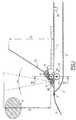
- Fig. 1 there is shown schematically a portion of a roof 1 of a motor vehicle, on the front part of which a windshield 2 is mounted via a seal 3.
- a lining 4 which provides an internal space 5 with said face for the passage for example of electric cables or for the positioning of fasteners for various accessories.
- On pavilion 1 of the motor vehicle is mounted a support for an antenna 10 and which comprises a base 6.
- the base 6 is provided with fixing members, not shown, on the pavilion 1 of this motor vehicle.
- antenna 10 is angularly movable, on the one hand, between a first position removed from flag 1 for good reception of the radio and shown in full line in this figure and, on the other hand, a second position folded down on this roof 1 and shown in dotted lines.
- the base 6 includes an element 11 angular displacement of the antenna 10 between the two positions, controlled by an obstacle detection means 20 A of height, with respect to pavilion 1, less than the distance dl separating the end of the antenna 10 and said flag 1 in the first position of this antenna 10.
- the element 11 of angular displacement of the antenna 10 is formed by an electric motor 12 whose output shaft 12a is provided with a pinion 13 meshing with a pinion 14 mounted on a horizontal axis 15 carried by the base 6 and integral in rotation with antenna 10.
- the assembly formed by the motor 12 and the pinion 13 is fixed, by suitable means not shown, on the internal face of pavilion 1 and between said pavilion 1 and the packing 4.
- the means 20 for detecting the obstacle A comprise a proximity sensor 21 disposed on the roof 1 in front of the antenna 10.
- the proximity sensor 21 is located in the front part of base 6.
- this sensor proximity 21 emits a detection field which presents itself, for example, in the form of a cone whose angle a and height d2 represent the values of this field and which are configurable.
- the proximity 21 When the vehicle is moving, the proximity 21 emits a detection field upwards the antenna 10 which is in the position away from the flag 1, as shown in solid lines in FIG. 1.
- the electric motor 12 is not supplied and the antenna 10 remains in this position.
- the latter commands the electric motor 12 to drive in rotation the output shaft 12a and the pinion 13.
- the pinion 13 drives the pinion 14 as well as axis 15 which has the effect of angularly moving the antenna 10 down so as to bring it into position flap kills flag 1, as shown in dotted lines in Fig. 1.
- antenna 10 remains in its position folded back against roof 1 so that it do not hit this obstacle A during the movement of the vehicle.
- this proximity sensor 21 After the passage of this obstacle A and in the case where the proximity sensor 21 does not detect another obstacle, this proximity sensor 21 emits a control signal motor 12 which drives, in reverse, the shaft of outlet 12a and the pinion 13.
- the tilting in the opposite direction of the antenna 10 to bring it back to the position away from the roof 1 is controlled by the proximity sensor 21 after a predetermined time so as to allow the passage of obstacle A.
- the means for detecting a obstacle include a first proximity sensor 21 disposed on roof 1 in front of antenna 10 and a second sensor proximity 22 disposed behind said antenna 10.
- the proximity sensor 21 controls the tilting of the antenna 10 in the case of the detection of a obstacle when driving the vehicle and the sensor proximity 22 controls the tilting of this antenna 10 in the event of an obstacle being detected while walking rear of this motor vehicle.
- Appropriate bodies are provided to arrest the engine when the antenna is in one or other of the positions.
- the different elements making up the antenna can be of modular type which allows to keep the mounting methods used so far for antennas traditional.
- the device therefore makes it possible to avoid the collision between the antenna and a possible obstacle, thus removing noise pollution for the occupants of the vehicle in the case this antenna taps against an obstacle and also avoiding the risks of damage to the reception antenna radio.
Landscapes
- Engineering & Computer Science (AREA)
- Remote Sensing (AREA)
- Details Of Aerials (AREA)
- Support Of Aerials (AREA)
- Fittings On The Vehicle Exterior For Carrying Loads, And Devices For Holding Or Mounting Articles (AREA)
- Input Circuits Of Receivers And Coupling Of Receivers And Audio Equipment (AREA)
Abstract
Description
La présente invention concerne une antenne, notamment de réception radio, pour un véhicule automobile.The present invention relates to an antenna, in particular radio reception, for a motor vehicle.
Les véhicules automobiles sont généralement livrés avec un ensemble de pré-équipement radio qui comprend notamment une antenne fixée sur un élément de la carrosserie et de plus en plus sur le pavillon du véhicule.Motor vehicles are generally delivered with a set of radio pre-equipment which includes in particular an antenna fixed to an element of the body and more and more on the roof of the vehicle.
Pour cela, l'antenne comporte un support se présentant sous la forme d'une embase qui est rapportée sur le pavillon et vissée de l'intérieur du véhicule.For this, the antenna includes a support having in the form of a base which is attached to the roof and screwed from inside the vehicle.
Pour pouvoir bénéficier d'une bonne réception de la radio, il est nécessaire d'avoir une inclinaison optimisée de l'antenne par rapport au pavillon du véhicule.To be able to receive good reception from radio, it is necessary to have an optimized tilt antenna in relation to the vehicle roof.
En effet, l'antenne doit être plus ou moins inclinée selon sa longueur de telle manière que la distance entre le pavillon et l'extrémité libre de cette antenne soit de l'ordre de 300mm afin d'obtenir une réception de la radio dans les meilleures conditions possibles.Indeed, the antenna must be more or less inclined according to its length so that the distance between the roof and the free end of this antenna either around 300mm in order to get radio reception in the best possible conditions.
Ainsi, pour obtenir une bonne réception de la radio, l'antenne forme avec le pavillon du véhicule un angle assez important ce qui augmente la hauteur du véhicule si bien que l'antenne peut facilement entrer en contact avec des obstacles lors du déplacement du véhicule, comme par exemple des entrées de garage ou des barres de calibrage d'entrée de parking.So to get good reception of the radio, the antenna forms an angle with the vehicle roof quite important which increases the height of the vehicle if although the antenna can easily come into contact with obstacles when moving the vehicle, such as example of driveways or calibration bars parking entrance.
Par- conséquent, en milieu urbain, il arrive fréquemment que l'antenne vienne taper sur un. obstacle et provoque une mise en résonance de celle-ci qui se caractérise par un bruit désagréable à l'intérieur du véhicule ou un risque de dégradation de l'antenne.Therefore, in urban areas, it happens frequently let the antenna hit a. obstacle and causes a resonance of this which is characterized by an unpleasant noise inside the vehicle or a risk of antenna degradation.
L'invention a pour but de proposer une antenne de véhicule automobile qui évite les inconvénients précédemment mentionnés.The object of the invention is to propose an antenna of motor vehicle which avoids the disadvantages previously mentioned.
L'invention a donc pour objet une antenne de véhicule automobile montée sur une embase munie d'organes de fixation sur le pavillon dudit véhicule automobile, caractérisée en ce que l'embase comporte un élément de déplacement angulaire de l'antenne entre une première position écartée du pavillon et une seconde position rabattue sur ce pavillon, commandé par des moyens de détection d'un obstacle de hauteur, par rapport au pavillon, inférieure à la distance séparant l'extrémité de l'antenne et ledit pavillon dans la première position de cette antenne.The invention therefore relates to a vehicle antenna automobile mounted on a base fitted with attachment to the roof of said motor vehicle, characterized in that the base has a displacement element angle of the antenna between a first spaced position of the roof and a second position folded over this roof, controlled by obstacle detection means in height, relative to the pavilion, less than the distance separating the end of the antenna and said pavilion in the first position of this antenna.
Selon d'autres caractéristiques de l'invention :
- l'élément de déplacement angulaire de l'antenne est formé par un moteur électrique dont l'arbre de sortie est muni d'un pignon engrenant avec un pignon monté sur un axe horizontal porté par l'embase et solidaire en rotation de ladite antenne,
- les moyens de détection d'un obstacle comprennent un capteur de proximité disposé sur le pavillon devant ladite antenne,
- les moyens de détection d'un obstacle comprennent un premier capteur de proximité disposé sur le pavillon devant l'antenne et un second capteur de proximité disposé derrière ladite antenne.
- the angular displacement element of the antenna is formed by an electric motor, the output shaft of which is provided with a pinion meshing with a pinion mounted on a horizontal axis carried by the base and integral in rotation with said antenna,
- the obstacle detection means include a proximity sensor placed on the roof in front of said antenna,
- the obstacle detection means comprise a first proximity sensor disposed on the roof in front of the antenna and a second proximity sensor disposed behind said antenna.
Les caractéristiques et avantages de l'invention apparaítront au cours de la description qui va suivre, donnée à titre d'exemple et faite en référence aux dessins annexés, sur lesquels :
- la Fig. 1 est une vue schématique en coupe longitudinale d'un support d'une antenne de véhicule automobile, conforme à l'invention,
- la Fig. 2 est une vue schématique en coupe selon la ligne 2-2 de la Fig. 1.
- Fig. 1 is a schematic view in longitudinal section of a support for a motor vehicle antenna, in accordance with the invention,
- Fig. 2 is a schematic sectional view along line 2-2 of FIG. 1.
Sur la Fig.1, on a représenté schématiquement
une portion d'un pavillon 1 d'un véhicule automobile, sur la
partie avant duquel est monté un pare-brise 2 par l'intermédiaire
d'un joint d'étanchéité 3.In Fig. 1, there is shown schematically
a portion of a roof 1 of a motor vehicle, on the
front part of which a
Sur la face interne du pavillon 1 est prévu un
garnissage 4 qui ménage avec ladite face un espace interne 5
pour le passage par exemple de câbles électriques ou pour
le positionnement d'organes de fixation de divers accessoires.On the internal face of the pavilion 1 is provided a
Sur le pavillon 1 du véhicule automobile est
monté un support d'une antenne 10 et qui comprend une embase
6.On pavilion 1 of the motor vehicle is
mounted a support for an
L'embase 6 est munie d'organes de fixation, non
représentés, sur le pavillon 1 de ce véhicule automobile.The
Ainsi, que représenté à la Fig. 1, l'antenne 10
est déplaçable angulairement, d'une part, entre une première
position écartée du pavillon 1 pour une bonne réception de
la radio et représentée en trait plein sur cette figure et,
d'autre part, une seconde position rabattue sur ce pavillon
1 et représentée en pointillés.Thus, as shown in FIG. 1,
A cet effet, l'embase 6 comporte un élément 11
de déplacement angulaire de l'antenne 10 entre les deux positions,
commandé par des moyens 20 de détection d'un obstacle
A de hauteur, par rapport au pavillon 1, inférieure à la
distance dl séparant l'extrémité de l'antenne 10 et ledit
pavillon 1 dans la première position de cette antenne 10.For this purpose, the
Comme représenté notamment à la Fig. 2, l'élément
11 de déplacement angulaire de l'antenne 10 est formé
par un moteur électrique 12 dont l'arbre de sortie 12a est
muni d'un pignon 13 engrenant avec un pignon 14 monté sur un
axe horizontal 15 porté par l'embase 6 et solidaire en rotation
avec l'antenne 10.As shown in particular in FIG. 2, the
L'ensemble formé par le moteur 12 et le pignon
13 est fixé, par des moyens appropriés non représentés, sur
la face interne du pavillon 1 et entre ledit pavillon 1 et
le garnissage 4.The assembly formed by the
Les moyens 20 de détection de l'obstacle A comprennent
un capteur de proximité 21 disposé sur le pavillon
1 devant l'antenne 10. The
Dans l'exemple de réalisation représenté sur les
figures, le capteur de proximité 21 est implanté dans la
partie avant de l'embase 6.In the embodiment shown on the
Figures, the
Ainsi que représenté à la Fig. 1, ce capteur de
proximité 21 émet un champ de détection qui se présente, par
exemple, sous la forme d'un cône dont l'angle a et la hauteur
d2 représentent les valeurs de ce champ et qui sont paramétrables.As shown in FIG. 1, this
Lors du déplacement du véhicule, le capteur de
proximité 21 émet vers le haut un champ de détection devant
l'antenne 10 qui est en position écartée du pavillon 1,
comme représentée en trait plein à la Fig. 1.When the vehicle is moving, the
Tant que le capteur de proximité 21 ne détecte
pas la présence de l'obstacle A, le moteur électrique 12
n'est pas alimenté et l'antenne 10 demeure dans cette position.As long as the
Dès que l'obstacle A entre dans le champ de détection
émis par le capteur de proximité 21, ce dernier commande
le moteur électrique 12 pour entraíner en rotation
l'arbre de sortie 12a et le pignon 13.As soon as obstacle A enters the detection field
emitted by the
Le pignon 13 entraíne le pignon 14 ainsi que
l'axe 15 ce qui a pour effet de déplacer angulairement l'antenne
10 vers le bas de façon à l'amener dans la position
rabat-tue sur le pavillon 1, comme représentée en pointillés
à la Fig. 1.The
Tant que le capteur de proximité 21 détecte la
présence de l'obstacle A, l'antenne 10 reste dans sa position
rabattue contre la pavillon 1 de telle manière qu'elle
ne tape pas contre cet obstacle A pendant le déplacement du
véhicule.As long as the
Après le passage de cet obstacle A et dans le
cas où le capteur de proximité 21 ne détecte pas un autre
obstacle, ce capteur de proximité 21 émet un signal de commande
du moteur 12 qui entraíne, en sens inverse, l'arbre de
sortie 12a et le pignon 13.After the passage of this obstacle A and in the
case where the
La rotation en sens inverse de ce pignon 13 provoque
par l'intermédiaire du pignon 14 et de l'axe 15 le pivotement
de l'antenne 10 de façon à la ramener dans sa position
écartée du pavillon 1 afin d'obtenir une réception de
la radio dans les meilleurs conditions.The opposite rotation of this
Le basculement en sens inverse de l'antenne 10
pour la ramener dans la position écartée du pavillon 1 est
commandé par le capteur de proximité 21 après un temps prédéterminé
de façon à permettre le passage de l'obstacle A.The tilting in the opposite direction of the
Selon une variante, les moyens de détection d'un
obstacle comprennent un premier capteur de proximité 21 disposé
sur le pavillon 1 devant l'antenne 10 et un second capteur
de proximité 22 disposé derrière ladite antenne 10.According to a variant, the means for detecting a
obstacle include a
Ainsi, le capteur de proximité 21 commande le
basculement de l'antenne 10 dans le cas de la détection d'un
obstacle lors de la marche avant du véhicule et le capteur
de proximité 22 commande le basculement de cette antenne 10
dans le cas de la détection d'un obstacle lors de la marche
arrière de ce véhicule automobile.Thus, the
Des organes appropriés sont prévus pour arrêter le moteur lorsque l'antenne est dans l'une ou l'autre des positions.Appropriate bodies are provided to arrest the engine when the antenna is in one or other of the positions.
Les différents éléments composant l'antenne peuvent être de type modulaire ce qui permet de conserver les procédés de montage utilisés jusqu'à présent pour les antennes traditionnelles.The different elements making up the antenna can be of modular type which allows to keep the mounting methods used so far for antennas traditional.
Le dispositif permet donc d'éviter la collision entre l'antenne et un obstacle éventuel, supprimant ainsi les nuisances sonores pour les occupants du véhicule dans le cas où cette antenne tape contre un obstacle et évitant également les risques de dégradations de l'antenne de réception radio.The device therefore makes it possible to avoid the collision between the antenna and a possible obstacle, thus removing noise pollution for the occupants of the vehicle in the case this antenna taps against an obstacle and also avoiding the risks of damage to the reception antenna radio.
Claims (4)
Applications Claiming Priority (2)
| Application Number | Priority Date | Filing Date | Title |
|---|---|---|---|
| FR9904896A FR2792463B1 (en) | 1999-04-19 | 1999-04-19 | MOTOR VEHICLE ANTENNA |
| FR9904896 | 1999-04-19 |
Publications (2)
| Publication Number | Publication Date |
|---|---|
| EP1047151A1 true EP1047151A1 (en) | 2000-10-25 |
| EP1047151B1 EP1047151B1 (en) | 2005-06-15 |
Family
ID=9544578
Family Applications (1)
| Application Number | Title | Priority Date | Filing Date |
|---|---|---|---|
| EP00401056A Expired - Lifetime EP1047151B1 (en) | 1999-04-19 | 2000-04-14 | Antenna for vehicle |
Country Status (4)
| Country | Link |
|---|---|
| EP (1) | EP1047151B1 (en) |
| AT (1) | ATE298136T1 (en) |
| DE (1) | DE60020769T2 (en) |
| FR (1) | FR2792463B1 (en) |
Cited By (2)
| Publication number | Priority date | Publication date | Assignee | Title |
|---|---|---|---|---|
| US7187250B2 (en) | 2001-12-20 | 2007-03-06 | Nxp B.V. | Coupler, integrated electronic component and electronic device |
| CN103192785A (en) * | 2013-04-25 | 2013-07-10 | 夏春蕾 | Whole monitoring system for three-dimensional space around vehicle |
Families Citing this family (1)
| Publication number | Priority date | Publication date | Assignee | Title |
|---|---|---|---|---|
| DE102019211755B3 (en) | 2019-08-06 | 2020-12-31 | Volkswagen Aktiengesellschaft | Mounting system for a modular antenna |
Citations (5)
| Publication number | Priority date | Publication date | Assignee | Title |
|---|---|---|---|---|
| US4514670A (en) * | 1982-07-16 | 1985-04-30 | Robert Bosch Gmbh | Electric positioning motor control system, particularly automatic vehicle antenna extension system |
| US4788551A (en) * | 1985-08-08 | 1988-11-29 | Nissan Motor Co., Ltd. | Apparatus for storing an antenna for vehicle |
| US5221929A (en) * | 1991-06-20 | 1993-06-22 | Ott Russell J | Hinged magnetic antenna mount |
| US5349361A (en) * | 1989-10-05 | 1994-09-20 | Harada Kogyo Kabushiki Kaisha | Three-wave antenna for vehicles |
| US5446472A (en) * | 1993-11-30 | 1995-08-29 | Winegard Company | System for raising and lowering an antenna |
-
1999
- 1999-04-19 FR FR9904896A patent/FR2792463B1/en not_active Expired - Fee Related
-
2000
- 2000-04-14 AT AT00401056T patent/ATE298136T1/en not_active IP Right Cessation
- 2000-04-14 DE DE60020769T patent/DE60020769T2/en not_active Expired - Fee Related
- 2000-04-14 EP EP00401056A patent/EP1047151B1/en not_active Expired - Lifetime
Patent Citations (5)
| Publication number | Priority date | Publication date | Assignee | Title |
|---|---|---|---|---|
| US4514670A (en) * | 1982-07-16 | 1985-04-30 | Robert Bosch Gmbh | Electric positioning motor control system, particularly automatic vehicle antenna extension system |
| US4788551A (en) * | 1985-08-08 | 1988-11-29 | Nissan Motor Co., Ltd. | Apparatus for storing an antenna for vehicle |
| US5349361A (en) * | 1989-10-05 | 1994-09-20 | Harada Kogyo Kabushiki Kaisha | Three-wave antenna for vehicles |
| US5221929A (en) * | 1991-06-20 | 1993-06-22 | Ott Russell J | Hinged magnetic antenna mount |
| US5446472A (en) * | 1993-11-30 | 1995-08-29 | Winegard Company | System for raising and lowering an antenna |
Cited By (2)
| Publication number | Priority date | Publication date | Assignee | Title |
|---|---|---|---|---|
| US7187250B2 (en) | 2001-12-20 | 2007-03-06 | Nxp B.V. | Coupler, integrated electronic component and electronic device |
| CN103192785A (en) * | 2013-04-25 | 2013-07-10 | 夏春蕾 | Whole monitoring system for three-dimensional space around vehicle |
Also Published As
| Publication number | Publication date |
|---|---|
| DE60020769T2 (en) | 2006-05-04 |
| EP1047151B1 (en) | 2005-06-15 |
| FR2792463A1 (en) | 2000-10-20 |
| FR2792463B1 (en) | 2004-03-12 |
| ATE298136T1 (en) | 2005-07-15 |
| DE60020769D1 (en) | 2005-07-21 |
Similar Documents
| Publication | Publication Date | Title |
|---|---|---|
| EP0972694B1 (en) | Electrically operated clamping device for adjusting the position of an element with respect to another | |
| FR2711955A1 (en) | Arrangement of the rear part of a motor vehicle comprising a rear window wiper and an additional rear brake light. | |
| FR2892993A1 (en) | Aerodynamic device for e.g. minivan, has deflector displaced by tilting between retracted position in which deflector is applied on external surface of plate and active position in which deflector is projected with respect to plate | |
| EP0499508A1 (en) | Steering column arrangement for an automotive vehicle | |
| EP1359053B9 (en) | Exterior vehicle rear view mirror | |
| EP1047151B1 (en) | Antenna for vehicle | |
| FR2669593A1 (en) | PROJECTOR CLEANING SYSTEM FOR THE FRONT AREA OF A MOTOR VEHICLE. | |
| FR2859426A1 (en) | EQUIPMENT MODULE TRIM WITH A WALL HAVING A REAR VISION CAMERA | |
| EP2331387A1 (en) | Arrangement for removing water from the roof of an automobile | |
| FR2543744A1 (en) | Antenna for car radio | |
| EP0438341A1 (en) | Streamlined windshield wiper, in particular for automobile vehicle | |
| WO2002040311A1 (en) | Motor vehicle front seat | |
| FR2848738A1 (en) | Electric motor for windscreen wiper device of automobile, has position determining unit fixed on output unit by crimping, where output unit has bearing surface following contour of determining unit axially installed to shaft | |
| FR2622521A1 (en) | Set of rear-view mirrors (retrovisors) for commercial vehicles | |
| FR2809368A1 (en) | Automobile steering column with anti-theft sleeve comprises telescopic steering shaft with rear section which slides axially in front section, sleeve in front of rear section has housings for lock bolt | |
| EP1357004A1 (en) | Arrangement for an opening of a vehicle body, using a breakable support for the windscreen wiper system | |
| EP0102339A2 (en) | Anti-theft device | |
| FR2823477A1 (en) | Warning signal for warning of opening of longitudinal sliding door on minivan, comprises illuminated triangle mounted on spring loaded arm which rises to horizontal position when sliding door is opened | |
| FR2782963A1 (en) | DEVICE FOR CONTROLLING A MOBILE PART OF A MOTOR VEHICLE PROJECTOR | |
| FR2963917A1 (en) | Vehicle i.e. motor vehicle, has steering member provided with steering column, and vehicle structure whose pion cooperates with steering column for preventing steering of steering wheels in adjustment position of given inclination | |
| EP1911640A1 (en) | Device for arranging an automobile windscreen wiper assembly | |
| EP0586306A2 (en) | Adjustable assembling system for a lighting- or indicating device of a vehicle on a fixed part of the vehicle and device fitted out with such a system | |
| EP1361114B1 (en) | Exterior rear view mirror with fixed housing | |
| EP3122576B1 (en) | Motor vehicle comprising running gear attachment guide means | |
| FR2905106A1 (en) | Motor vehicle`s steering assembly, has steering column rotatably integrated to shaft, where shaft has end integrated to sprocket gearing with another sprocket to rotatably drive steering column when steering wheel turns around another shaft |
Legal Events
| Date | Code | Title | Description |
|---|---|---|---|
| PUAI | Public reference made under article 153(3) epc to a published international application that has entered the european phase |
Free format text: ORIGINAL CODE: 0009012 |
|
| AK | Designated contracting states |
Kind code of ref document: A1 Designated state(s): AT BE CH CY DE DK ES FI FR GB GR IE IT LI LU MC NL PT SE |
|
| AX | Request for extension of the european patent |
Free format text: AL;LT;LV;MK;RO;SI |
|
| 17P | Request for examination filed |
Effective date: 20000926 |
|
| AKX | Designation fees paid |
Free format text: AT BE CH CY DE DK ES FI FR GB GR IE IT LI LU MC NL PT SE |
|
| GRAP | Despatch of communication of intention to grant a patent |
Free format text: ORIGINAL CODE: EPIDOSNIGR1 |
|
| GRAS | Grant fee paid |
Free format text: ORIGINAL CODE: EPIDOSNIGR3 |
|
| GRAA | (expected) grant |
Free format text: ORIGINAL CODE: 0009210 |
|
| AK | Designated contracting states |
Kind code of ref document: B1 Designated state(s): AT BE CH CY DE DK ES FI FR GB GR IE IT LI LU MC NL PT SE |
|
| PG25 | Lapsed in a contracting state [announced via postgrant information from national office to epo] |
Ref country code: FI Free format text: LAPSE BECAUSE OF FAILURE TO SUBMIT A TRANSLATION OF THE DESCRIPTION OR TO PAY THE FEE WITHIN THE PRESCRIBED TIME-LIMIT Effective date: 20050615 Ref country code: NL Free format text: LAPSE BECAUSE OF FAILURE TO SUBMIT A TRANSLATION OF THE DESCRIPTION OR TO PAY THE FEE WITHIN THE PRESCRIBED TIME-LIMIT Effective date: 20050615 Ref country code: IE Free format text: LAPSE BECAUSE OF FAILURE TO SUBMIT A TRANSLATION OF THE DESCRIPTION OR TO PAY THE FEE WITHIN THE PRESCRIBED TIME-LIMIT Effective date: 20050615 Ref country code: AT Free format text: LAPSE BECAUSE OF FAILURE TO SUBMIT A TRANSLATION OF THE DESCRIPTION OR TO PAY THE FEE WITHIN THE PRESCRIBED TIME-LIMIT Effective date: 20050615 |
|
| REG | Reference to a national code |
Ref country code: GB Ref legal event code: FG4D Free format text: NOT ENGLISH Ref country code: CH Ref legal event code: EP |
|
| REF | Corresponds to: |
Ref document number: 60020769 Country of ref document: DE Date of ref document: 20050721 Kind code of ref document: P |
|
| GBT | Gb: translation of ep patent filed (gb section 77(6)(a)/1977) |
Effective date: 20050706 |
|
| REG | Reference to a national code |
Ref country code: IE Ref legal event code: FG4D Free format text: LANGUAGE OF EP DOCUMENT: FRENCH |
|
| PG25 | Lapsed in a contracting state [announced via postgrant information from national office to epo] |
Ref country code: DK Free format text: LAPSE BECAUSE OF FAILURE TO SUBMIT A TRANSLATION OF THE DESCRIPTION OR TO PAY THE FEE WITHIN THE PRESCRIBED TIME-LIMIT Effective date: 20050915 Ref country code: GR Free format text: LAPSE BECAUSE OF FAILURE TO SUBMIT A TRANSLATION OF THE DESCRIPTION OR TO PAY THE FEE WITHIN THE PRESCRIBED TIME-LIMIT Effective date: 20050915 Ref country code: SE Free format text: LAPSE BECAUSE OF FAILURE TO SUBMIT A TRANSLATION OF THE DESCRIPTION OR TO PAY THE FEE WITHIN THE PRESCRIBED TIME-LIMIT Effective date: 20050915 |
|
| PG25 | Lapsed in a contracting state [announced via postgrant information from national office to epo] |
Ref country code: ES Free format text: LAPSE BECAUSE OF FAILURE TO SUBMIT A TRANSLATION OF THE DESCRIPTION OR TO PAY THE FEE WITHIN THE PRESCRIBED TIME-LIMIT Effective date: 20050926 |
|
| PG25 | Lapsed in a contracting state [announced via postgrant information from national office to epo] |
Ref country code: PT Free format text: LAPSE BECAUSE OF FAILURE TO SUBMIT A TRANSLATION OF THE DESCRIPTION OR TO PAY THE FEE WITHIN THE PRESCRIBED TIME-LIMIT Effective date: 20051124 |
|
| NLV1 | Nl: lapsed or annulled due to failure to fulfill the requirements of art. 29p and 29m of the patents act | ||
| REG | Reference to a national code |
Ref country code: IE Ref legal event code: FD4D |
|
| PG25 | Lapsed in a contracting state [announced via postgrant information from national office to epo] |
Ref country code: MC Free format text: LAPSE BECAUSE OF NON-PAYMENT OF DUE FEES Effective date: 20060430 Ref country code: BE Free format text: LAPSE BECAUSE OF NON-PAYMENT OF DUE FEES Effective date: 20060430 Ref country code: CH Free format text: LAPSE BECAUSE OF NON-PAYMENT OF DUE FEES Effective date: 20060430 Ref country code: LI Free format text: LAPSE BECAUSE OF NON-PAYMENT OF DUE FEES Effective date: 20060430 |
|
| PLBE | No opposition filed within time limit |
Free format text: ORIGINAL CODE: 0009261 |
|
| STAA | Information on the status of an ep patent application or granted ep patent |
Free format text: STATUS: NO OPPOSITION FILED WITHIN TIME LIMIT |
|
| 26N | No opposition filed |
Effective date: 20060316 |
|
| REG | Reference to a national code |
Ref country code: CH Ref legal event code: PL |
|
| REG | Reference to a national code |
Ref country code: GB Ref legal event code: 746 Effective date: 20070118 |
|
| BERE | Be: lapsed |
Owner name: PEUGEOT CITROEN AUTOMOBILES SA Effective date: 20060430 |
|
| PGFP | Annual fee paid to national office [announced via postgrant information from national office to epo] |
Ref country code: GB Payment date: 20080326 Year of fee payment: 9 |
|
| PG25 | Lapsed in a contracting state [announced via postgrant information from national office to epo] |
Ref country code: LU Free format text: LAPSE BECAUSE OF NON-PAYMENT OF DUE FEES Effective date: 20060414 |
|
| PGFP | Annual fee paid to national office [announced via postgrant information from national office to epo] |
Ref country code: DE Payment date: 20080408 Year of fee payment: 9 |
|
| PGFP | Annual fee paid to national office [announced via postgrant information from national office to epo] |
Ref country code: IT Payment date: 20080409 Year of fee payment: 9 |
|
| PG25 | Lapsed in a contracting state [announced via postgrant information from national office to epo] |
Ref country code: CY Free format text: LAPSE BECAUSE OF FAILURE TO SUBMIT A TRANSLATION OF THE DESCRIPTION OR TO PAY THE FEE WITHIN THE PRESCRIBED TIME-LIMIT Effective date: 20050615 |
|
| GBPC | Gb: european patent ceased through non-payment of renewal fee |
Effective date: 20090414 |
|
| REG | Reference to a national code |
Ref country code: FR Ref legal event code: ST Effective date: 20091231 |
|
| PG25 | Lapsed in a contracting state [announced via postgrant information from national office to epo] |
Ref country code: DE Free format text: LAPSE BECAUSE OF NON-PAYMENT OF DUE FEES Effective date: 20091103 |
|
| PG25 | Lapsed in a contracting state [announced via postgrant information from national office to epo] |
Ref country code: FR Free format text: LAPSE BECAUSE OF NON-PAYMENT OF DUE FEES Effective date: 20091222 Ref country code: GB Free format text: LAPSE BECAUSE OF NON-PAYMENT OF DUE FEES Effective date: 20090414 |
|
| PGFP | Annual fee paid to national office [announced via postgrant information from national office to epo] |
Ref country code: FR Payment date: 20080429 Year of fee payment: 9 |
|
| PG25 | Lapsed in a contracting state [announced via postgrant information from national office to epo] |
Ref country code: IT Free format text: LAPSE BECAUSE OF NON-PAYMENT OF DUE FEES Effective date: 20090414 |