EP1048314A1 - Medical instrument positioning device internal to a catheter or lead - Google Patents
Medical instrument positioning device internal to a catheter or lead Download PDFInfo
- Publication number
- EP1048314A1 EP1048314A1 EP00107318A EP00107318A EP1048314A1 EP 1048314 A1 EP1048314 A1 EP 1048314A1 EP 00107318 A EP00107318 A EP 00107318A EP 00107318 A EP00107318 A EP 00107318A EP 1048314 A1 EP1048314 A1 EP 1048314A1
- Authority
- EP
- European Patent Office
- Prior art keywords
- tubular member
- inner tubular
- positioning device
- medical
- distal end
- Prior art date
- Legal status (The legal status is an assumption and is not a legal conclusion. Google has not performed a legal analysis and makes no representation as to the accuracy of the status listed.)
- Granted
Links
Images


Classifications
-
- A—HUMAN NECESSITIES
- A61—MEDICAL OR VETERINARY SCIENCE; HYGIENE
- A61M—DEVICES FOR INTRODUCING MEDIA INTO, OR ONTO, THE BODY; DEVICES FOR TRANSDUCING BODY MEDIA OR FOR TAKING MEDIA FROM THE BODY; DEVICES FOR PRODUCING OR ENDING SLEEP OR STUPOR
- A61M25/00—Catheters; Hollow probes
- A61M25/01—Introducing, guiding, advancing, emplacing or holding catheters
- A61M25/0105—Steering means as part of the catheter or advancing means; Markers for positioning
-
- A—HUMAN NECESSITIES
- A61—MEDICAL OR VETERINARY SCIENCE; HYGIENE
- A61M—DEVICES FOR INTRODUCING MEDIA INTO, OR ONTO, THE BODY; DEVICES FOR TRANSDUCING BODY MEDIA OR FOR TAKING MEDIA FROM THE BODY; DEVICES FOR PRODUCING OR ENDING SLEEP OR STUPOR
- A61M25/00—Catheters; Hollow probes
- A61M25/0021—Catheters; Hollow probes characterised by the form of the tubing
- A61M25/0041—Catheters; Hollow probes characterised by the form of the tubing pre-formed, e.g. specially adapted to fit with the anatomy of body channels
-
- A—HUMAN NECESSITIES
- A61—MEDICAL OR VETERINARY SCIENCE; HYGIENE
- A61M—DEVICES FOR INTRODUCING MEDIA INTO, OR ONTO, THE BODY; DEVICES FOR TRANSDUCING BODY MEDIA OR FOR TAKING MEDIA FROM THE BODY; DEVICES FOR PRODUCING OR ENDING SLEEP OR STUPOR
- A61M25/00—Catheters; Hollow probes
- A61M25/01—Introducing, guiding, advancing, emplacing or holding catheters
- A61M25/0105—Steering means as part of the catheter or advancing means; Markers for positioning
- A61M25/0133—Tip steering devices
- A61M25/0152—Tip steering devices with pre-shaped mechanisms, e.g. pre-shaped stylets or pre-shaped outer tubes
Definitions
- This invention relates to an improved medical positioning device for the precise positioning of a medical treatment instrument into an interior organ.
- the present medical positioning device penetrates selected tissue to precisely position a medical treatment instrument into an interior organ while minimizing trauma to tissue surrounding the treatment site. By minimizing trauma to surrounding tissue, the medical positioning device allows for greater medical benefits while minimizing side effects.
- This invention is particularly useful for guiding and positioning a catheter or an electrical stimulation lead into the brain along a non-linear insertion path.
- a straight, solid metal wire called a stylet
- a straight insertion of a catheter using a wire stylet has drawbacks that prevent the optimal placement of a medical treatment instrument.
- the straight insertion of an instrument into some portions of the brain would pass through other critical brain areas, which control a patient's sensory or bodily functions, thereby possibly causing damage to a patient's speech, hearing, or sight.
- a linear insertion route would require insertion through other undesirable locations that would cause increased trauma to the patient.
- a surgeon wishes to guide a catheter or lead into the brain while avoiding these critical brain areas.
- U.S. Pat. No. 5,195,968 to Lundquist shows a catheter steering mechanism utilizing a pull wire type guiding system.
- Pull wire type guiding systems have been used primarily to place a catheter into the heart by way of coronary veins.
- U.S. Pat. No. 4,873,983 to Winters U.S. Pat. No. 4,917,102 to Miller et al, and U.S. Pat. No. 5,308,324 to Hammerslag et al, show flexible movable core guide wires.
- Flexible movable core guide wires have been primarily used to insert a catheter through the coronary arteries.
- prior art positioning devices are less suitable for use in solid, soft tissue interior organs, such as the brain.
- Known prior art devices have been used primarily in open cavities that are hollow or filled only with a liquid such as blood. Because open cavities are essentially hollow, a surgeon may move a medical positioning device from side to side within the hollow cavity without damaging tissue by the device's side to side movement. In a solid interior organ, like the brain, however, side to side movement would cause sensitive tissue to be damaged or even sliced.
- a surgeon used a pull wire guiding system or a movable core guide wire system to insert a catheter or lead into the brain, it would damage or slice brain tissue. Additionally, movable core guide wires may be excessively flexible and not strong enough to be effectively used for inserting a treatment instrument into and through brain tissue. Because of these drawbacks, surgeons have typically not used pull wire guiding systems or movable core guide wire systems for placing medical treatment instruments into the brain. Instead, brain surgeons have generally used straight stylets for the straight, linear insertion of a medical treatment device into the brain. Thus, there is a need for a medical positioning device that will allow for the precise placement of medical treatment devices into soft tissue interior organs along a curved path with minimal or non-existent, critical lateral or slicing movement.
- the present invention is an improved medical positioning device which allows the user to precisely position a catheter or lead into the brain following a non-linear or curved insertion path while minimizing or even eliminating unwanted damage to surrounding brain tissue and trauma to a patient.
- the present medical positioning device allows a catheter, a lead, or other medical treatment instrument to be precisely placed into an interior organ along a curved, nonlinear path.
- the present invention is particularly suitable for use in the brain.
- the present invention allows a surgeon to guide a catheter or lead to a specific treatment site into an interior organ following a predetermined nonlinear insertion path designed to avoid critical structures within the organ.
- the present invention additionally allows for the precise placement of a treatment device along a non-linear or curved insertion path with minimal damage to tissue surrounding the targeted treatment site.
- the present positioning device provides A medical positioning device for introducing a medical treatment instrument through a surgical opening in a body and guiding the position of said treatment instrument within interior organs of said body, said medical positioning device comprising:
- the inner tubular member is elastically deformable, the curved portion of the inner tubular member temporarily straightens when it is placed substantially inside the outer tubular member.
- the superelastic property of the inner tubular member allows it to elastically return to its original curvature when it passes outwardly through the outer tubular member and into bodily tissue.
- the innermost member is placed inside the inner tubular member and is slidably movable within the inner tubular member. Once the three components are assembled, they are placed within a medical treatment device such as a catheter or lead. Alternatively, the medical treatment instrument is placed within the outer tubular member. In this configuration, the superelastic inner tubular member and the innermost member are slidably movable within the medical treatment instrument.
- a surgeon inserts the outer tubular member into the body until it penetrates a selected organ to a predetermined depth near the treatment site. Once the outer tubular member has been inserted to the proper depth, the surgeon fixes the position of the outer tubular member. The surgeon then advances the elastically deformable inner tubular member out the end of the outer tubular member to bring it closer to the treatment site. When exiting the outer tubular member, the inner tubular member elastically resumes its curvature and advances outwardly along a curved path into and through the organ. Once the superelastic inner tubular member has been advanced to its desired location, the surgeon fixes its position. Next, the surgeon advances the innermost member out the end of the inner tubular member until it reaches the treatment site.
- the medical treatment instrument As each of the three components is inserted into the body, the medical treatment instrument is also advanced. Thus, the advancement of the innermost member brings the treatment instrument to the treatment site. After the surgeon has stabilized the medical treatment device, for example, a catheter or stimulation lead, in the organ, the surgeon retracts the innermost member, the inner tubular member, and outer tubular member from the patient's body.
- the medical treatment device for example, a catheter or stimulation lead
- the medical positioning device embodying the present invention is generally depicted by the numeral 40 and comprises, in combination, an outer tubular member 42, an inner tubular member 44 and an innermost member 46.
- the outer tubular member 42, the inner tubular member 44, and the innermost member 46 are internal to a medical treatment instrument 50.
- FIG. 1 shows a medical treatment instrument 50 that has been inserted into the brain along a non-linear, or curved insertion path to a position within the brain.
- the treatment instrument 50 is a catheter or stimulation lead.
- the present medical positioning device may be used with other medical treatment instruments.
- the outer tubular member 42 is substantially linear.
- the outer tubular member 42 has a proximal end 60, a distal end 62, and an axial bore 64 therethrough.
- the outer tubular member 42 is substantially linear and rigid to allow its insertion through a surgical opening in the body and into organ tissue.
- the distal end 62 is inserted into an opening in the body and the proximal end 60 remains outside the body.
- the outer diameter of the outer tubular member 42 is as small as possible to minimize trauma and damage to the tissue of the patient during surgery.
- the outer diameter of the outer tubular member is less than 1.24 mm (0.050 inches), more preferably, the outer diameter of the outer tubular member is less than 1 mm (0.040 inches), and most preferably between 0.75 and 1mm (0.030 and 0.040 inches).
- the outer tubular member should preferably sufficiently long to be able to reach the targeted treatment site.
- the outer tubular member will be less than 60 cm (24 inches) long, preferably between28 - 40 cm (11 and 16 inches) long.
- the outer tubular member 42 preferably has a circular cross sectional shape.
- the outer tubular member 42 is typically manufactured from a material which is sufficiently rigid so that it may be inserted through a hole in a patient's body and into an interior organ. Additionally, it should be sufficiently rigid so that at least the outer tubular member's distal portion 62 may be placed in proximity to the selected treatment site. Most preferably, the outer tubular member 42 has a greater rigidity than the inner tubular member 44 such that the outer tubular member 42 remains substantially linear when the inner tubular member 44 is positioned substantially within the outer tubular member 42.
- the outer tubular member 42 can be manufactured from any inert material which is nontoxic and nonreactive with bodily tissue and that can be formed into substantially linear shapes. For example, materials from which the outer tubular member may be produced include metals such as stainless steel and tungsten.
- the inner tubular member 44 has a proximal end 66, a distal end 68, an axial bore therethrough 70 and a curvature 48.
- the distal end 68 of the inner tubular member 44 is inserted into the body while the proximal end 66 of the inner tubular member 44 remains outside of the body.
- the distal end 68 of the inner tubular member 44 has a curvature 48, however, the entire inner tubular member 44 may have a curvature.
- the invention contemplates providing the surgeon with a series of inner tubular members that cover a range of curvatures. During a surgical planning session, the surgeon will determine which inner tubular member of the series to use during surgery.
- the amount of curvature will be dependent on the target site within the organ and the surgeon's desired insertion route for the medical treatment device.
- the typical value for the bend radius of curvature would be between 1.25 and 6.75 mm (0.05 and 0.25 inches).
- the radius of curvature is measured from the devices neutral axis which is the centerline of the device. Larger values are also contemplated.
- the inner tubular member 44 has an outer diameter which is less than the inner diameter of the outer tubular member 42 so that it may be positioned within the outer tubular member 42.
- the outer diameter of the inner tubular member is approximately 0.5 mm (0.020 inches).
- a range of diameters between 0.25 - 0.75 mm (0.010 - 0.030 inches) are also contemplated for use in the present invention.
- the inner tubular member 44 is fabricated from a superelastic material which allows the inner tubular member to be elastically deformable.
- the material should be sufficiently elastic such that the inner tubular member 44 is capable of essentially returning to its original curvature 48 upon removal of a force which causes the curvature 48 to temporarily straighten.
- the inner tubular member 44 When the inner tubular member 44 is positioned substantially within the entirety of the linear outer tubular member 42, the inner tubular member 44 temporarily straightens and becomes selectively linear.
- the inner tubular member 44 outwardly exits the distal end 62 of the outer tubular member 42 it is sufficiently elastically deformable to allow the inner tubular member 42 to essentially resume its original curvature 48.
- the elastically deformable inner tubular member 44 is manufactured from a Ni-Ti binary alloy having superelastic properties.
- Ni-Ti binary alloy having superelastic properties.
- Many commercial companies manufacture and sell suitable Ni-Ti alloys.
- Raychem Corp. of Menlo Park, California sells a Ni-Ti alloy under the trade name Tinel® and Nitinol Device & Components of Fremont, California sells a suitable Ni-Ti alloy, SE-508, under the trade name Nitinol®.
- the binary Ni-Ti alloy has between 48.0 and 52.0 percent atomic weight of Ni, more preferably between 50 and 51 percent, and most preferably between 50.6 and 51.0 percent atomic weight of Ni. Other weight percent ratios are also contemplated for use in this invention.
- Ni-Ti binary alloy is the preferred material for the superelastic inner tubular member, one of skill in the art will appreciate that other materials, such as other metals, plastics, polymers, and synthetics, which exhibit similar superelastic properties may be suitable for use in the present invention.
- the entire inner tubular member 44 is fabricated from the superelastic material described above.
- the inner tubular member 44 may be manufactured from a combination of materials.
- the distal portion 68 of the inner tubular member 44 having a curvature 48 may be composed of a elastically deformable material described herein and the proximal portion 66 of the inner tubular member 44 may be composed of a more rigid material such as a metal like stainless steel or tungsten.
- the innermost member 46 has a proximal end 72 and a distal end 74.
- the innermost member 46 is a straight, solid wire fabricated from a metal such as tungsten or stainless steel. Flat stylets are also contemplated for use.
- FIG. 11 shows the member 46 bent for representative purposes only.
- the innermost member 46 should be sufficiently rigid to allow it to penetrate soft bodily tissue, such as brain tissue.
- the distal portion 72 of the innermost member 46 has an outer diameter less than the inner diameter of the inner tubular member 44 so that the innermost member 46 is slidably movable within the inner tubular member 44.
- the distal end 74 of the stylet 46 has a ball or other enlargement that aids in the advancement of the medical treatment instrument 50 to the targeted treatment site.
- the stylet should be sufficiently long such that the proximal end 72 of the stylet extends beyond the proximal end 66 of the inner tubular member 44 when the stylet is inserted into the body.
- the inner tubular member will be approximately 27.5 to 4.0 cm (11 - 16 inches) in length.
- the innermost tubular member should be dimensioned and fabricated in such a manner that it will freely slide through the curved inner tubular member without kinking.
- the outer diameter of the innermost member 46 is less than 0.5 mm (0.020 inches).
- the outer diameter of the stylet will be dependent on the percent strain recovery of the chosen material, the radius of curvature of the inner tubular member, and the diameter of the inner tubular member.
- the percent strain of the innermost member is equal to the one half its outer diameter divided by its radius of curvature. For stainless steel, a typical percent strain recovery is approximately 2 percent or less. Typical values for Ni-Ti alloys are in the 6 - 8 percent range, however, other alloys or materials may have values outside this range.
- fabricating the innermost member from a Ni-Ti alloy will allow it to pass through an inner tubular member 44 having a smaller radius of curvature without kinking.
- a stainless steel stylet having 2 percent recoverable strain could have a radius of curvature typically about 6.75 cm (0.25 inches) and a diameter of 0.5 mm (0.020 inches).
- a Ni-Ti stylet having 8 percent recoverable strain and an outer diameter of 0.5 mm (0.020 inches) could have a radius of curvature as small as 2.5 mm (0.10 inches).
- FIGS. 2-6 and 12 show the spatial relationship of the components comprising the medical positioning device in the preferred embodiment.
- the inner tubular member 44 is inwardly spaced from the outer tubular member 42.
- the distal end 68 of the elastically deformable inner tubular member 44 is inserted into the axial bore 64 at the proximal end 60 of the outer tubular member 42.
- the innermost member 46 is inwardly spaced from the inner tubular member 44.
- the proximal end 72 of the innermost member 46 is inserted into the axial bore 70 of the outer tubular member 42.
- the outer tubular member 42, the inner tubular member 44, and the innermost member 46 are slidably movable within each other and are selectively positionable. These three components are placed internal to a medical treatment instrument 50.
- the three components When the three components are advanced in a position of use, they form a non-linear structure within an organ that defines a non-linear insertion path for a medical treatment instrument 50. As demonstrated in FIGS. 4-6, these three components are advanced, the medical treatment instrument 50 is guided and precisely positioned into an interior organ along the defined non-linear insertion path.
- FIG. 13 An additional configuration of the invention is contemplated and shown in FIG. 13.
- a medical treatment device 92 is positioned within an outer tubular member 90.
- a superelastic inner tubular member 94 having a curvature is positioned within the medical treatment device 92 and is slidably movable therein.
- An innermost member 96 is positioned within the superelastic inner tubular member 94 and is slidably movable therein.
- the outer tubular member 90, the inner tubular member 94, and the innermost member 96 will be fabricated from the similar materials and will have similar properties as those in the preferred embodiment previously discussed.
- a surgeon may determine that the linear insertion of a medical treatment instrument into the brain would pass through or damage critical brain areas.
- the present invention will allow a surgeon to plan and execute the insertion of a medical treatment device into the body via a non-linear insertion trajectory.
- a surgeon may avoid damaging critical structures in the body, and in particular, the brain.
- the surgeon could access targeted treatment sites from a non-linear trajectory.
- Neurological system is defined broadly in this application to include the brain, the spinal cord, nerves, ganglia, and parts of the receptor organs that receives or interprets stimuli and transmits impulses to the effector organs.
- Particular sites within the brain where the non-linear placement of a medical treatment device may be desirable include, for example, the subthalamic nucleus (STN), the peduncular pontine nucleus (PPN), the caudate or putamen, the internal and external palladium, the cingulum, the anterior limb of the internal capsule, the anterior nucleus (AN), the centremedian (CM), the dorsal medial nucleus and other nuclei of the thalamus, the hippocampus and other structures in the temporal lobe, the hypothalamus and other structures of the diencephalon, the pons, and the medulla.
- STN subthalamic nucleus
- PPN peduncular pontine nucleus
- AN anterior nucleus
- CM centremedian
- the dorsal medial nucleus and other nuclei of the thalamus the hippocampus and other structures in the temporal lobe
- the present medical positioning device will allow for a medical treatment device to reach a treatment site along an insertion path that is, in part, an essentially horizontal direction.
- the present medical positioning device may allow for the substantially horizontal or lateral placement of the medical treatment device.
- the present horizontal placement of medical treatment devices may be particularly well suited for placing a medical treatment device into the globus pallidus or striatum of the brain.
- the present invention may also be well suited for the placement of medical devices near the sacral nerve or the spinal cord. For example, the linear insertion and placement of a stimulation lead would traverse through the foramen and cross the sacral nerve.
- the present positioning device may be suitable for placing a stimulation lead parallel to the sacral nerve for optimal treatment.
- FIGS. 4-6 show how the individual components are advanced for the nonlinear insertion of the medical treatment instrument 50 into an organ. Once each of the three principal components has been finally advanced, the medical treatment instrument 50 will have been inserted into an organ to the targeted treatment site along a nonlinear path. After the medical instrument 50 has been positioned, the surgeon may treat various ailments and diseases via the medical treatment instrument.
- the surgeon inserts the substantially linear outer tubular member 42 into the organ being treated, such as a brain.
- the depth to which the outer tubular member 42 is placed will depend on the location of the site targeted for treatment. The surgeon will determine where to insert the outer tubular member 42 so that it will be positioned near the target site while avoiding critical organ structures.
- the surgeon fixes its position. Once fixed, the distal end 60 of the outer tubular member 42 defines a longitudinal axis which further defines a first insertion direction a.
- the present invention further comprises an inner tubular member advancement knob.
- the inner tubular member advancement knob allows the surgeon to precisely advance the inner tubular manner 44.
- numerous mechanisms which allow the controlled advancement of tubular parts such as vernier devices, thumb screws, slides, etc., may be suitable for use with the present medical positioning device.
- the outer surface of the inner tubular member 44 will have a plurality of equally spaced apart radial marks 80 as shown in FIG. 12.
- the radial marks 80 are spaced apart in millimeter increments.
- the radial marks 80 allow the surgeon to visually determine the distance the distal end 68 of the inner tubular member 44 extends beyond the distal end 62 of the outer tubular member 44.
- the inner tubular member 44 preferably is longer than the outer tubular member 42 and is generally between 20 and 60 cm (8 and 24 inches) long, more preferably between 20 and 40 (8 and 16 inches) in length.
- the radial marks will additionally allow the surgeon to determine how far into the patient the inner tubular member 44 has been inserted.
- the inner tubular member 44 Because the inner tubular member 44 is fabricated from a superelastic material, it will resume its curvature 48 as it exits the distal end 62 of the outer tubular member 42 and will advance on a known curvilinear trajectory shown by the dashed line (C) in FIG. 5.
- the curvilinear trajectory (C) the inner tubular member 44 tracks upon exiting from the outer tubular member 42 will be dependent on the curvature 48 of the inner tubular member 44.
- FIG. 7 shows an outer tubular member 42 having an alignment mark 68 at its proximal end 60.
- FIG. 12 shows an inner tubular member 44 having an axial alignment mark 84 extending along its longitudinal side.
- the surgeon fixes the inner tubular member relative to the outer tubular member 42.
- a set screw fixes the inner tubular member 44 relative to the outer tubular member 42.
- the distal end 68 of the inner tubular member 44 defines a second insertion direction ⁇ which is divergent from the first insertion direction a as shown in FIG. 5.
- the second insertion direction ⁇ is essentially tangent to the curvilinear trajectory (c) of the inner tubular member 44 at its distal end 68.
- ⁇ will be essentially 90 degrees from vertical.
- the surgeon may stabilize the medical instrument 50 prior to removal of the medical positioning device 40.
- the stylet 46 can be withdrawn.
- the inner tubular member 44 may be withdrawn, followed by the outer tubular member 42.
- the catheter or lead has been inserted into the brain along a nonlinear insertion path.
- a similar method of use is contemplated for the medical positioning device shown in FIG. 13.
- the surgeon inserts the outer tubular member 90 through a surgical opening and brings it near the treatment site.
- the superelastic inner tubular member 92 is advanced along a curvilinear trajectory into the organ and brought close to the targeted treatment site.
- the surgeon positions the innermost member 96 to the targeted treatment site.
- this method will allow a surgeon to place a medical treatment instrument into the brain along a nonlinear insertion path while avoiding neurological zones within the brain that contain critical brain structures.
- the present medical positioning device advantageously allows for the non-linear deployment of a catheter or lead into an interior organ.
- the present invention allows the surgeon to avoid critical brain structures that a linear insertion of a medical treatment device would hit.
- the present invention has the additional advantage of having repeatable results because the superelastic inner tubular member will automatically, and repeatably resume its original curvature.
- the repeatability of the medical positioning device allows for the predictable insertion of the medical instrument to the targeted treatment site.
- the present invention advantageously allows the surgeon to position a medical treatment device into the brain in a controlled manner while avoiding critical neurological zones.
Abstract
Description
- This invention relates to an improved medical positioning device for the precise positioning of a medical treatment instrument into an interior organ. The present medical positioning device penetrates selected tissue to precisely position a medical treatment instrument into an interior organ while minimizing trauma to tissue surrounding the treatment site. By minimizing trauma to surrounding tissue, the medical positioning device allows for greater medical benefits while minimizing side effects. This invention is particularly useful for guiding and positioning a catheter or an electrical stimulation lead into the brain along a non-linear insertion path.
- In many medical procedures, it is necessary to position a catheter or an electrical stimulation lead at a precise location within a patient's body. Often, precise placement of a medical treatment instrument is difficult because of the location of the treatment site in the body. These difficult treatment sites may be nearby critical body organs, nerves, or other components that are at high risk of being damaged while the instrument is moved to the treatment site.
- The placement of catheters and leads into the body, and particularly into the brain, has been primarily in a straight, linear manner. To place the catheter or lead straight into the brain, a straight, solid metal wire, called a stylet, is used. For many potential treatment sites, a straight insertion of a catheter using a wire stylet has drawbacks that prevent the optimal placement of a medical treatment instrument. For example, the straight insertion of an instrument into some portions of the brain would pass through other critical brain areas, which control a patient's sensory or bodily functions, thereby possibly causing damage to a patient's speech, hearing, or sight. For other portions of the brain, a linear insertion route would require insertion through other undesirable locations that would cause increased trauma to the patient. Ideally, a surgeon wishes to guide a catheter or lead into the brain while avoiding these critical brain areas. To avoid these critical brain areas, it has been found to be desirable to insert the medical treatment instrument into the brain along a curved or nonlinear path, so as to allow a surgeon to precisely place a catheter or stimulation lead into the brain on an insertion path that avoids damage to critical brain tissue.
- A number of prior art positioning devices exist that allow for the non-linear placement of a catheter or lead into the body. For example, U.S. Pat. No. 5,195,968 to Lundquist shows a catheter steering mechanism utilizing a pull wire type guiding system. Pull wire type guiding systems have been used primarily to place a catheter into the heart by way of coronary veins. Also, U.S. Pat. No. 4,873,983 to Winters, U.S. Pat. No. 4,917,102 to Miller et al, and U.S. Pat. No. 5,308,324 to Hammerslag et al, show flexible movable core guide wires. Flexible movable core guide wires have been primarily used to insert a catheter through the coronary arteries.
- The placement of medical treatment instruments into interior organs presents an additional challenge that makes prior art positioning devices less suitable for use in solid, soft tissue interior organs, such as the brain. Known prior art devices have been used primarily in open cavities that are hollow or filled only with a liquid such as blood. Because open cavities are essentially hollow, a surgeon may move a medical positioning device from side to side within the hollow cavity without damaging tissue by the device's side to side movement. In a solid interior organ, like the brain, however, side to side movement would cause sensitive tissue to be damaged or even sliced.
- If a surgeon used a pull wire guiding system or a movable core guide wire system to insert a catheter or lead into the brain, it would damage or slice brain tissue. Additionally, movable core guide wires may be excessively flexible and not strong enough to be effectively used for inserting a treatment instrument into and through brain tissue. Because of these drawbacks, surgeons have typically not used pull wire guiding systems or movable core guide wire systems for placing medical treatment instruments into the brain. Instead, brain surgeons have generally used straight stylets for the straight, linear insertion of a medical treatment device into the brain. Thus, there is a need for a medical positioning device that will allow for the precise placement of medical treatment devices into soft tissue interior organs along a curved path with minimal or non-existent, critical lateral or slicing movement.
- The present invention is an improved medical positioning device which allows the user to precisely position a catheter or lead into the brain following a non-linear or curved insertion path while minimizing or even eliminating unwanted damage to surrounding brain tissue and trauma to a patient.
- The present medical positioning device allows a catheter, a lead, or other medical treatment instrument to be precisely placed into an interior organ along a curved, nonlinear path. The present invention is particularly suitable for use in the brain. The present invention allows a surgeon to guide a catheter or lead to a specific treatment site into an interior organ following a predetermined nonlinear insertion path designed to avoid critical structures within the organ. The present invention additionally allows for the precise placement of a treatment device along a non-linear or curved insertion path with minimal damage to tissue surrounding the targeted treatment site.
- In summary, the present positioning device provides A medical positioning device for introducing a medical treatment instrument through a surgical opening in a body and guiding the position of said treatment instrument within interior organs of said body, said medical positioning device comprising:
- an outer tubular member having a proximal end and a distal end, said outer tubular member being substantially linear;
- an inner tubular member slidably movable within said outer tubular member, said inner tubular member having a proximal end and a distal end, said distal end of said inner tubular member having a curvature, said inner tubular member being elastically deformable for allowing said distal end of said inner tubular member to become selectively linear when positioned substantially within the entirety of said linear outer tubular member and to essentially resume said curvature when exiting said distal end of said outer tubular member; and
- an innermost member slidably moveable within said inner tubular member, said innermost member having a proximal end and a distal end, said distal end of said innermost member being movable outwardly from said distal end of said inner tubular member, said distal end of said inner tubular member, and said distal end of said innermost member being selectively positionable for defining an interior structure for guiding said treatment instrument to the desired position within a selected interior organ of said body.
-
- Because the inner tubular member is elastically deformable, the curved portion of the inner tubular member temporarily straightens when it is placed substantially inside the outer tubular member. The superelastic property of the inner tubular member allows it to elastically return to its original curvature when it passes outwardly through the outer tubular member and into bodily tissue. The innermost member is placed inside the inner tubular member and is slidably movable within the inner tubular member. Once the three components are assembled, they are placed within a medical treatment device such as a catheter or lead. Alternatively, the medical treatment instrument is placed within the outer tubular member. In this configuration, the superelastic inner tubular member and the innermost member are slidably movable within the medical treatment instrument.
- In operation, a surgeon inserts the outer tubular member into the body until it penetrates a selected organ to a predetermined depth near the treatment site. Once the outer tubular member has been inserted to the proper depth, the surgeon fixes the position of the outer tubular member. The surgeon then advances the elastically deformable inner tubular member out the end of the outer tubular member to bring it closer to the treatment site. When exiting the outer tubular member, the inner tubular member elastically resumes its curvature and advances outwardly along a curved path into and through the organ. Once the superelastic inner tubular member has been advanced to its desired location, the surgeon fixes its position. Next, the surgeon advances the innermost member out the end of the inner tubular member until it reaches the treatment site. As each of the three components is inserted into the body, the medical treatment instrument is also advanced. Thus, the advancement of the innermost member brings the treatment instrument to the treatment site. After the surgeon has stabilized the medical treatment device, for example, a catheter or stimulation lead, in the organ, the surgeon retracts the innermost member, the inner tubular member, and outer tubular member from the patient's body.
- These and other advantages of the invention will become more apparent from the following detailed description thereof, given by way of example only, when taken in conjunction with the following drawings and description of the preferred embodiment.
- The preferred embodiments of the invention will be described in relation to the accompanying drawings. In the drawings, the following figures have the following general nature:
- FIG. 1 is a schematic of the brain showing a stimulation lead or catheter inserted into the brain along a non-linear insertion path.
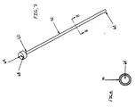
- FIG. 2 is a pictorial view of the medical positioning device.
- FIG. 3 is an enlarged, broken cross sectional view
of the medical positioning device, at
View 3 of FIG. 2. - FIG. 4 is an enlarged, truncated pictorial view of the preferred embodiment of the invention of FIGS. 2 and 3 with the outer tubular member advanced in a position of use.
- FIG. 5 is an enlarged, truncated pictorial view of the preferred embodiment of the invention of FIGS. 2 and 3 with the outer tubular member and the superelastic inner tubular member advanced to a position of use.
- FIG. 6 is an enlarged, truncated pictorial view of the preferred embodiment of the invention of FIGS. 2 and 3 with the outer tubular member, the superelastic inner tubular member, and the innermost member advanced to a position of use.
- FIG. 7 is a pictorial view of the outer tubular member in the preferred embodiment of the medical positioning device of FIGS. 2 and 3.
- FIG. 8 is a cross sectional view of the outer tubular member taken along line 8-8 shown in FIG. 7.
- FIG. 9 is a side elevational view of the superelastic inner tubular member in the preferred embodiment of the medical positioning device of FIGS. 2 and 3.
- FIG. 10 is an enlarged, cross sectional view of the superelastic inner tubular member taken along the line 10-10 of FIG. 9.
- FIG. 11 is a side elevational view of the innermost member, shown bent for assembly representation purposes only, in the preferred embodiment of the medical positioning device of FIGS. 2 and 3.
- FIG. 12 is a front elevation view of the preferred embodiment of the medical positioning device.
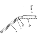
- FIG. 13 is an alternative embodiment of the medical positioning device.
-
- As illustrated in FIG. 2, the medical positioning device embodying the present invention is generally depicted by the numeral 40 and comprises, in combination, an
outer tubular member 42, aninner tubular member 44 and aninnermost member 46. In the preferred embodiment, the outertubular member 42, theinner tubular member 44, and theinnermost member 46 are internal to amedical treatment instrument 50. - FIG. 1 shows a
medical treatment instrument 50 that has been inserted into the brain along a non-linear, or curved insertion path to a position within the brain. In the preferred embodiment, thetreatment instrument 50 is a catheter or stimulation lead. One of skill in the art would appreciate that the present medical positioning device may be used with other medical treatment instruments. - Referring to FIGS. 7 and 8, the outer
tubular member 42 is substantially linear. The outertubular member 42 has a proximal end 60, adistal end 62, and anaxial bore 64 therethrough. Generally, the outertubular member 42 is substantially linear and rigid to allow its insertion through a surgical opening in the body and into organ tissue. In use, thedistal end 62 is inserted into an opening in the body and the proximal end 60 remains outside the body. Preferably, the outer diameter of the outertubular member 42 is as small as possible to minimize trauma and damage to the tissue of the patient during surgery. Preferably, the outer diameter of the outer tubular member is less than 1.24 mm (0.050 inches), more preferably, the outer diameter of the outer tubular member is less than 1 mm (0.040 inches), and most preferably between 0.75 and 1mm (0.030 and 0.040 inches). The outer tubular member should preferably sufficiently long to be able to reach the targeted treatment site. Generally, the outer tubular member will be less than 60 cm (24 inches) long, preferably between28 - 40 cm (11 and 16 inches) long. As shown in FIG. 8, the outertubular member 42 preferably has a circular cross sectional shape. - The outer
tubular member 42 is typically manufactured from a material which is sufficiently rigid so that it may be inserted through a hole in a patient's body and into an interior organ. Additionally, it should be sufficiently rigid so that at least the outer tubular member'sdistal portion 62 may be placed in proximity to the selected treatment site. Most preferably, the outertubular member 42 has a greater rigidity than theinner tubular member 44 such that the outertubular member 42 remains substantially linear when theinner tubular member 44 is positioned substantially within the outertubular member 42. The outertubular member 42 can be manufactured from any inert material which is nontoxic and nonreactive with bodily tissue and that can be formed into substantially linear shapes. For example, materials from which the outer tubular member may be produced include metals such as stainless steel and tungsten. - Referring to FIGS. 9 and 10, the
inner tubular member 44 has aproximal end 66, adistal end 68, an axial bore therethrough 70 and acurvature 48. In operation, thedistal end 68 of theinner tubular member 44 is inserted into the body while theproximal end 66 of theinner tubular member 44 remains outside of the body. Preferably, only thedistal end 68 of theinner tubular member 44 has acurvature 48, however, the entireinner tubular member 44 may have a curvature. The invention contemplates providing the surgeon with a series of inner tubular members that cover a range of curvatures. During a surgical planning session, the surgeon will determine which inner tubular member of the series to use during surgery. The amount of curvature will be dependent on the target site within the organ and the surgeon's desired insertion route for the medical treatment device. The typical value for the bend radius of curvature would be between 1.25 and 6.75 mm (0.05 and 0.25 inches). The radius of curvature is measured from the devices neutral axis which is the centerline of the device. Larger values are also contemplated. Theinner tubular member 44 has an outer diameter which is less than the inner diameter of the outertubular member 42 so that it may be positioned within the outertubular member 42. Typically, the outer diameter of the inner tubular member is approximately 0.5 mm (0.020 inches). However, a range of diameters between 0.25 - 0.75 mm (0.010 - 0.030 inches) are also contemplated for use in the present invention. - In the preferred embodiment, the
inner tubular member 44 is fabricated from a superelastic material which allows the inner tubular member to be elastically deformable. The material should be sufficiently elastic such that theinner tubular member 44 is capable of essentially returning to itsoriginal curvature 48 upon removal of a force which causes thecurvature 48 to temporarily straighten. When theinner tubular member 44 is positioned substantially within the entirety of the linear outertubular member 42, theinner tubular member 44 temporarily straightens and becomes selectively linear. When theinner tubular member 44 outwardly exits thedistal end 62 of the outertubular member 42, it is sufficiently elastically deformable to allow theinner tubular member 42 to essentially resume itsoriginal curvature 48. - In the preferred embodiment, the elastically deformable
inner tubular member 44 is manufactured from a Ni-Ti binary alloy having superelastic properties. Many commercial companies manufacture and sell suitable Ni-Ti alloys. For example, Raychem Corp. of Menlo Park, California sells a Ni-Ti alloy under the trade name Tinel® and Nitinol Device & Components of Fremont, California sells a suitable Ni-Ti alloy, SE-508, under the trade name Nitinol®. In the preferred embodiment, the binary Ni-Ti alloy has between 48.0 and 52.0 percent atomic weight of Ni, more preferably between 50 and 51 percent, and most preferably between 50.6 and 51.0 percent atomic weight of Ni. Other weight percent ratios are also contemplated for use in this invention. Metals that exhibit superelastic or pseudoelastic properties have the unusual ability to undergo large elastic deformation and also exhibit non-linear unloading behavior. Superelastic metals generally have much greater elasticity, or springback, as compared to stainless steel. Thus, superelasticity allows one to pass a curved instrument through a straight, tubular member and the instrument will elastically return to its curvature once it passes outwardly through the tubular member. Although Ni-Ti binary alloy is the preferred material for the superelastic inner tubular member, one of skill in the art will appreciate that other materials, such as other metals, plastics, polymers, and synthetics, which exhibit similar superelastic properties may be suitable for use in the present invention. - Typically, the entire
inner tubular member 44 is fabricated from the superelastic material described above. In an alternative embodiment, theinner tubular member 44 may be manufactured from a combination of materials. For example, thedistal portion 68 of theinner tubular member 44 having acurvature 48 may be composed of a elastically deformable material described herein and theproximal portion 66 of theinner tubular member 44 may be composed of a more rigid material such as a metal like stainless steel or tungsten. - Referring to FIG. 11, the
innermost member 46, or stylet, has a proximal end 72 and adistal end 74. Typically, theinnermost member 46 is a straight, solid wire fabricated from a metal such as tungsten or stainless steel. Flat stylets are also contemplated for use. FIG. 11 shows themember 46 bent for representative purposes only. Theinnermost member 46 should be sufficiently rigid to allow it to penetrate soft bodily tissue, such as brain tissue. Preferably, the distal portion 72 of theinnermost member 46 has an outer diameter less than the inner diameter of theinner tubular member 44 so that theinnermost member 46 is slidably movable within theinner tubular member 44. Preferably, thedistal end 74 of thestylet 46 has a ball or other enlargement that aids in the advancement of themedical treatment instrument 50 to the targeted treatment site. The stylet should be sufficiently long such that the proximal end 72 of the stylet extends beyond theproximal end 66 of theinner tubular member 44 when the stylet is inserted into the body. Typically, the inner tubular member will be approximately 27.5 to 4.0 cm (11 - 16 inches) in length. - The innermost tubular member should be dimensioned and fabricated in such a manner that it will freely slide through the curved inner tubular member without kinking. Preferably, the outer diameter of the
innermost member 46 is less than 0.5 mm (0.020 inches). The outer diameter of the stylet will be dependent on the percent strain recovery of the chosen material, the radius of curvature of the inner tubular member, and the diameter of the inner tubular member. The percent strain of the innermost member is equal to the one half its outer diameter divided by its radius of curvature. For stainless steel, a typical percent strain recovery is approximately 2 percent or less. Typical values for Ni-Ti alloys are in the 6 - 8 percent range, however, other alloys or materials may have values outside this range. Fabricating the innermost member from a Ni-Ti alloy will allow it to pass through aninner tubular member 44 having a smaller radius of curvature without kinking. For example, in use, a stainless steel stylet having 2 percent recoverable strain could have a radius of curvature typically about 6.75 cm (0.25 inches) and a diameter of 0.5 mm (0.020 inches). Comparatively, a Ni-Ti stylet having 8 percent recoverable strain and an outer diameter of 0.5 mm (0.020 inches) could have a radius of curvature as small as 2.5 mm (0.10 inches). - FIGS. 2-6 and 12 show the spatial relationship of the components comprising the medical positioning device in the preferred embodiment. The
inner tubular member 44 is inwardly spaced from the outertubular member 42. Thedistal end 68 of the elastically deformableinner tubular member 44 is inserted into theaxial bore 64 at the proximal end 60 of the outertubular member 42. Theinnermost member 46 is inwardly spaced from theinner tubular member 44. The proximal end 72 of theinnermost member 46 is inserted into theaxial bore 70 of the outertubular member 42. In operation, the outertubular member 42, theinner tubular member 44, and theinnermost member 46 are slidably movable within each other and are selectively positionable. These three components are placed internal to amedical treatment instrument 50. When the three components are advanced in a position of use, they form a non-linear structure within an organ that defines a non-linear insertion path for amedical treatment instrument 50. As demonstrated in FIGS. 4-6, these three components are advanced, themedical treatment instrument 50 is guided and precisely positioned into an interior organ along the defined non-linear insertion path. - An additional configuration of the invention is contemplated and shown in FIG. 13. In this embodiment, a
medical treatment device 92 is positioned within anouter tubular member 90. A superelastic inner tubular member 94 having a curvature is positioned within themedical treatment device 92 and is slidably movable therein. Aninnermost member 96 is positioned within the superelastic inner tubular member 94 and is slidably movable therein. The outertubular member 90, the inner tubular member 94, and theinnermost member 96 will be fabricated from the similar materials and will have similar properties as those in the preferred embodiment previously discussed. - During surgical planning, a surgeon may determine that the linear insertion of a medical treatment instrument into the brain would pass through or damage critical brain areas. The present invention will allow a surgeon to plan and execute the insertion of a medical treatment device into the body via a non-linear insertion trajectory. By using the present medical positioning device, a surgeon may avoid damaging critical structures in the body, and in particular, the brain. Alternatively, the surgeon could access targeted treatment sites from a non-linear trajectory.
- There are numerous potential treatment sites within structures in the body, where it is desirable for a surgeon to precisely place a catheter or lead into an organ along a nonlinear path. Although target treatment sites may be reached using a linear insertion path, surgical planning may indicate that the optimal lead or catheter insertion path is nonlinear. In particular, there are numerous sites within the neurological system where the use of this invention may be advantageous. Neurological system is defined broadly in this application to include the brain, the spinal cord, nerves, ganglia, and parts of the receptor organs that receives or interprets stimuli and transmits impulses to the effector organs. Particular sites within the brain where the non-linear placement of a medical treatment device may be desirable include, for example, the subthalamic nucleus (STN), the peduncular pontine nucleus (PPN), the caudate or putamen, the internal and external palladium, the cingulum, the anterior limb of the internal capsule, the anterior nucleus (AN), the centremedian (CM), the dorsal medial nucleus and other nuclei of the thalamus, the hippocampus and other structures in the temporal lobe, the hypothalamus and other structures of the diencephalon, the pons, and the medulla.
- For other potential treatment sites, surgical planning may indicate that the optimal placement of catheter or lead is substantially horizontal rather than vertical. The present medical positioning device will allow for a medical treatment device to reach a treatment site along an insertion path that is, in part, an essentially horizontal direction. By selectively advancing the inner tubular member varying the radius of
curvature 48 on theinner tubular member 44, the present medical positioning device may allow for the substantially horizontal or lateral placement of the medical treatment device. The present horizontal placement of medical treatment devices may be particularly well suited for placing a medical treatment device into the globus pallidus or striatum of the brain. The present invention may also be well suited for the placement of medical devices near the sacral nerve or the spinal cord. For example, the linear insertion and placement of a stimulation lead would traverse through the foramen and cross the sacral nerve. The present positioning device may be suitable for placing a stimulation lead parallel to the sacral nerve for optimal treatment. - In use, the outer
tubular member 42, theinner tubular member 44, and theinnermost member 46 are assembled and inserted within a catheter or lead. The selective advancement of the outertubular member 42, theinner tubular member 44, and theinnermost member 46 will guide the catheter or lead to the desired treatment site. FIGS. 4-6 show how the individual components are advanced for the nonlinear insertion of themedical treatment instrument 50 into an organ. Once each of the three principal components has been finally advanced, themedical treatment instrument 50 will have been inserted into an organ to the targeted treatment site along a nonlinear path. After themedical instrument 50 has been positioned, the surgeon may treat various ailments and diseases via the medical treatment instrument. - Referring to FIG. 4, the surgeon inserts the substantially linear outer
tubular member 42 into the organ being treated, such as a brain. The depth to which the outertubular member 42 is placed will depend on the location of the site targeted for treatment. The surgeon will determine where to insert the outertubular member 42 so that it will be positioned near the target site while avoiding critical organ structures. After the outertubular member 42 is placed to the desired depth and proximate to the targeted treatment site, the surgeon fixes its position. Once fixed, the distal end 60 of the outertubular member 42 defines a longitudinal axis which further defines a first insertion direction a. - Next, the surgeon selectively advances the
inner tubular member 44 out thedistal end 62 of the outertubular member 42 as shown in FIG. 5. In the preferred embodiment, the present invention further comprises an inner tubular member advancement knob. The inner tubular member advancement knob allows the surgeon to precisely advance the innertubular manner 44. One of skill in the art will appreciate that numerous mechanisms which allow the controlled advancement of tubular parts, such as vernier devices, thumb screws, slides, etc., may be suitable for use with the present medical positioning device. In the preferred embodiment, the outer surface of theinner tubular member 44 will have a plurality of equally spaced apartradial marks 80 as shown in FIG. 12. Preferably, the radial marks 80 are spaced apart in millimeter increments. The radial marks 80 allow the surgeon to visually determine the distance thedistal end 68 of theinner tubular member 44 extends beyond thedistal end 62 of the outertubular member 44. Theinner tubular member 44 preferably is longer than the outertubular member 42 and is generally between 20 and 60 cm (8 and 24 inches) long, more preferably between 20 and 40 (8 and 16 inches) in length. The radial marks will additionally allow the surgeon to determine how far into the patient theinner tubular member 44 has been inserted. - Because the
inner tubular member 44 is fabricated from a superelastic material, it will resume itscurvature 48 as it exits thedistal end 62 of the outertubular member 42 and will advance on a known curvilinear trajectory shown by the dashed line (C) in FIG. 5. The curvilinear trajectory (C) theinner tubular member 44 tracks upon exiting from the outertubular member 42 will be dependent on thecurvature 48 of theinner tubular member 44. After choosing the optimal or desired insertion path of the medical treatment instrument to the treatment site, a surgeon will be able to selectively determine thecurvature 48 necessary for themedical instrument 50 to advance along the optimal insertion path. - To insure that the
inner tubular member 44 exits the outertubular member 42 in the desired direction, the outertubular member 42 and innertubular member 44 have corresponding alignment marks that may be visually aligned. When the marks are in alignment, theinner tubular member 44 will exit the outertubular member 42 in the predetermined direction. FIG. 7 shows anouter tubular member 42 having analignment mark 68 at its proximal end 60. FIG. 12 shows aninner tubular member 44 having anaxial alignment mark 84 extending along its longitudinal side. - After the surgeon selectively advances the
inner tubular member 44 to the desired point along curvilinear trajectory (C), the surgeon fixes the inner tubular member relative to the outertubular member 42. In the preferred embodiment, a set screw fixes theinner tubular member 44 relative to the outertubular member 42. After the position of the inner tubular member has been fixed, thedistal end 68 of theinner tubular member 44 defines a second insertion direction β which is divergent from the first insertion direction a as shown in FIG. 5. The second insertion direction β is essentially tangent to the curvilinear trajectory (c) of theinner tubular member 44 at itsdistal end 68. For treatment sites that call for the horizontal placement of a medical instrument, β will be essentially 90 degrees from vertical. After the surgeon advances the inner tubular member to the desired location, thestylet 46 is selectively advanced along the second insertion direction β outwardly from thedistal end 68 of theinner tubular member 44 as shown in FIG. 6. - Because the components of the present medical positioning device invention are internal to the
medical treatment instrument 50, the surgeon may stabilize themedical instrument 50 prior to removal of themedical positioning device 40. Once themedical treatment instrument 50 has been advanced to its final placement point, thestylet 46 can be withdrawn. Next, theinner tubular member 44 may be withdrawn, followed by the outertubular member 42. Thus, the catheter or lead has been inserted into the brain along a nonlinear insertion path. - A similar method of use is contemplated for the medical positioning device shown in FIG. 13. For this device, the surgeon inserts the outer
tubular member 90 through a surgical opening and brings it near the treatment site. Next, the superelastic innertubular member 92 is advanced along a curvilinear trajectory into the organ and brought close to the targeted treatment site. Next, the surgeon positions theinnermost member 96 to the targeted treatment site. As with the previously discussed method, this method will allow a surgeon to place a medical treatment instrument into the brain along a nonlinear insertion path while avoiding neurological zones within the brain that contain critical brain structures. - The present medical positioning device advantageously allows for the non-linear deployment of a catheter or lead into an interior organ. Advantageously, the present invention allows the surgeon to avoid critical brain structures that a linear insertion of a medical treatment device would hit. The present invention has the additional advantage of having repeatable results because the superelastic inner tubular member will automatically, and repeatably resume its original curvature. Advantageously, the repeatability of the medical positioning device allows for the predictable insertion of the medical instrument to the targeted treatment site. Lastly, the present invention advantageously allows the surgeon to position a medical treatment device into the brain in a controlled manner while avoiding critical neurological zones.
Claims (9)
- A medical positioning device for introducing a medical treatment instrument through a surgical opening in a body and guiding the position of said treatment instrument within interior organs of said body, said medical positioning device comprising:an outer tubular member (42) having a proximal end (60) and a distal end (62), said outer tubular member being substantially linear;an inner tubular member (44) slidably movable within said outer tubular member, said inner tubular member having a proximal end (60) and a distal end (68), said distal end of said inner tubular member having a curvature, said inner tubular member being elastically deformable for allowing said distal end of said inner tubular member to become selectively linear when positioned substantially within the entirety of said linear outer tubular member and to essentially resume said curvature when exiting said distal end of said outer tubular member; andan innermost member (46) slidably moveable within said inner tubular member, said innermost member having a proximal end (72) and a distal end (74), said distal end of said innermost member being movable outwardly from said distal end of said inner tubular member, said distal end of said inner tubular member, and said distal end of said innermost member being selectively positionable for defining an interior structure for guiding said treatment instrument to the desired position within a selected interior organ of said body.
- The medical positioning device of claim 1 wherein said inner tubular member (44) is fabricated from a superelastic material.
- The medical positioning device of claim 2 wherein said inner tubular member (44) is fabricated from a Ni-Ti binary alloy.
- The medical positioning device of any preceding claim wherein said innermost member (46) is fabricated from a superelastic material.
- The medical positioning device of claim 4 wherein said innermost member (46) is fabricated from a binary Ni-Ti alloy.
- The medical positioning device of any preceding claim wherein said medical treatment instrument is an electrical lead.
- The medical positioning device of any of claims 1 to 5, wherein said medical treatment instrument is a catheter.
- The medical positioning device of any preceding claim said medical positioning device sized, constructed, and arranged for the medical treatment of the brain.
- The medical positioning device of any preceding claim wherein said inner tubular member (44), said outer tubular member (42), and said innermost member (46) are concentric relative to each other.
Applications Claiming Priority (2)
| Application Number | Priority Date | Filing Date | Title |
|---|---|---|---|
| US301958 | 1999-04-29 | ||
| US09/301,958 US6214016B1 (en) | 1999-04-29 | 1999-04-29 | Medical instrument positioning device internal to a catheter or lead and method of use |
Publications (2)
| Publication Number | Publication Date |
|---|---|
| EP1048314A1 true EP1048314A1 (en) | 2000-11-02 |
| EP1048314B1 EP1048314B1 (en) | 2005-11-30 |
Family
ID=23165648
Family Applications (1)
| Application Number | Title | Priority Date | Filing Date |
|---|---|---|---|
| EP00107318A Expired - Lifetime EP1048314B1 (en) | 1999-04-29 | 2000-04-04 | Medical instrument positioning device internal to a catheter or lead |
Country Status (3)
| Country | Link |
|---|---|
| US (2) | US6214016B1 (en) |
| EP (1) | EP1048314B1 (en) |
| DE (1) | DE60024351T2 (en) |
Cited By (1)
| Publication number | Priority date | Publication date | Assignee | Title |
|---|---|---|---|---|
| WO2007128064A1 (en) | 2006-05-08 | 2007-11-15 | Cathrx Ltd | Shape imparting mechanism insertion |
Families Citing this family (120)
| Publication number | Priority date | Publication date | Assignee | Title |
|---|---|---|---|---|
| IL128261A0 (en) | 1999-01-27 | 1999-11-30 | Disc O Tech Medical Tech Ltd | Expandable element |
| US6440138B1 (en) * | 1998-04-06 | 2002-08-27 | Kyphon Inc. | Structures and methods for creating cavities in interior body regions |
| US7621950B1 (en) | 1999-01-27 | 2009-11-24 | Kyphon Sarl | Expandable intervertebral spacer |
| US20030220646A1 (en) * | 2002-05-23 | 2003-11-27 | Thelen Sarah L. | Method and apparatus for reducing femoral fractures |
| US6676665B2 (en) * | 2000-08-11 | 2004-01-13 | Sdgi Holdings, Inc. | Surgical instrumentation and method for treatment of the spine |
| US7072328B2 (en) * | 2001-01-12 | 2006-07-04 | Voicegenie Technologies Inc. | Computer-implemented voice markup language-based server |
| US7150737B2 (en) | 2001-07-13 | 2006-12-19 | Sci/Med Life Systems, Inc. | Methods and apparatuses for navigating the subarachnoid space |
| US7011647B2 (en) * | 2001-07-13 | 2006-03-14 | Scimed Life Systems, Inc. | Introducer sheath |
| US20030093105A1 (en) * | 2001-07-13 | 2003-05-15 | Scimed Life Systems, Inc. | Guide catheter for introduction into the subarachnoid space and methods of use thereof |
| US7455666B2 (en) * | 2001-07-13 | 2008-11-25 | Board Of Regents, The University Of Texas System | Methods and apparatuses for navigating the subarachnoid space |
| CN1835720B (en) * | 2001-07-25 | 2011-09-28 | Disc整形外科技术股份有限公司 | Deformable tools and implants |
| US7066953B2 (en) * | 2001-10-12 | 2006-06-27 | Rosengart Todd K | Method and apparatus for performing an anastamosis |
| US6814751B2 (en) | 2001-10-12 | 2004-11-09 | Rosengart Todd K | Method and apparatus for performing an anastamosis |
| US6824552B2 (en) * | 2002-04-03 | 2004-11-30 | Stryker Corporation | Surgical cutting accessory with nickel titanium alloy cutting head |
| US7953497B1 (en) | 2002-08-06 | 2011-05-31 | Boston Scientific Neuromodulation Corporation | Insertion stylet |
| US20040102830A1 (en) * | 2002-11-22 | 2004-05-27 | Williams Terrell M. | System for coupling an implanatable medical device to an epicardial site |
| US6860875B2 (en) * | 2002-11-25 | 2005-03-01 | Chaosong Hsue | Method and apparatuses of using foramen catheter needle scope to induce temporary blockade of sacral nerves |
| US20050075680A1 (en) | 2003-04-18 | 2005-04-07 | Lowry David Warren | Methods and systems for intracranial neurostimulation and/or sensing |
| DE60335037D1 (en) * | 2003-03-14 | 2010-12-30 | Depuy Spine Inc | HYDRAULIC DEVICE FOR BONE CEMENT INJECTION IN PERCUTANEOUS VERTEBROPLASTY |
| US8066713B2 (en) | 2003-03-31 | 2011-11-29 | Depuy Spine, Inc. | Remotely-activated vertebroplasty injection device |
| US7241283B2 (en) * | 2003-04-25 | 2007-07-10 | Ad-Tech Medical Instrument Corp. | Method for intracranial catheter treatment of brain tissue |
| US7789979B2 (en) | 2003-05-02 | 2010-09-07 | Gore Enterprise Holdings, Inc. | Shape memory alloy articles with improved fatigue performance and methods therefor |
| US7595306B2 (en) * | 2003-06-09 | 2009-09-29 | Alnylam Pharmaceuticals Inc | Method of treating neurodegenerative disease |
| US8415407B2 (en) | 2004-03-21 | 2013-04-09 | Depuy Spine, Inc. | Methods, materials, and apparatus for treating bone and other tissue |
| CA2432810A1 (en) * | 2003-06-19 | 2004-12-19 | Andres M. Lozano | Method of treating depression, mood disorders and anxiety disorders by brian infusion |
| AU2004261290A1 (en) | 2003-08-01 | 2005-02-10 | Northstar Neuroscience, Inc. | Apparatus and methods for applying neural stimulation to a patient |
| WO2005030034A2 (en) | 2003-09-26 | 2005-04-07 | Depuy Spine, Inc. | Device for delivering viscous material |
| US8019437B2 (en) * | 2004-02-05 | 2011-09-13 | Medtronic, Inc. | Lead fixation means |
| US7641664B2 (en) | 2004-02-12 | 2010-01-05 | Warsaw Orthopedic, Inc. | Surgical instrumentation and method for treatment of a spinal structure |
| EP2249529B1 (en) * | 2004-03-23 | 2019-01-16 | NDS Limited | Optimally adapting multimedia content for mobile subscriber device playback |
| EP1750800A1 (en) * | 2004-04-30 | 2007-02-14 | Advanced Neuromodulation Systems, Inc. | Method of treating mood disorders and/or anxiety disorders by brain stimulation |
| CA2570798A1 (en) * | 2004-06-16 | 2006-01-05 | Warsaw Orthopedic, Inc. | Surgical instrumentation for the repair of vertebral bodies |
| CN106963464B (en) | 2004-07-30 | 2019-11-05 | 德普伊新特斯产品有限责任公司 | Surgical set |
| US20060052856A1 (en) | 2004-09-08 | 2006-03-09 | Kim Daniel H | Stimulation components |
| US20120277839A1 (en) | 2004-09-08 | 2012-11-01 | Kramer Jeffery M | Selective stimulation to modulate the sympathetic nervous system |
| US9205261B2 (en) | 2004-09-08 | 2015-12-08 | The Board Of Trustees Of The Leland Stanford Junior University | Neurostimulation methods and systems |
| US20110190772A1 (en) | 2004-10-15 | 2011-08-04 | Vahid Saadat | Powered tissue modification devices and methods |
| US9101386B2 (en) | 2004-10-15 | 2015-08-11 | Amendia, Inc. | Devices and methods for treating tissue |
| US8430881B2 (en) * | 2004-10-15 | 2013-04-30 | Baxano, Inc. | Mechanical tissue modification devices and methods |
| US7887538B2 (en) | 2005-10-15 | 2011-02-15 | Baxano, Inc. | Methods and apparatus for tissue modification |
| US7963915B2 (en) | 2004-10-15 | 2011-06-21 | Baxano, Inc. | Devices and methods for tissue access |
| US7857813B2 (en) | 2006-08-29 | 2010-12-28 | Baxano, Inc. | Tissue access guidewire system and method |
| US8257356B2 (en) | 2004-10-15 | 2012-09-04 | Baxano, Inc. | Guidewire exchange systems to treat spinal stenosis |
| US8048080B2 (en) | 2004-10-15 | 2011-11-01 | Baxano, Inc. | Flexible tissue rasp |
| US9247952B2 (en) | 2004-10-15 | 2016-02-02 | Amendia, Inc. | Devices and methods for tissue access |
| EP1799129B1 (en) | 2004-10-15 | 2020-11-25 | Baxano, Inc. | Devices for tissue removal |
| US20100331883A1 (en) | 2004-10-15 | 2010-12-30 | Schmitz Gregory P | Access and tissue modification systems and methods |
| US8221397B2 (en) * | 2004-10-15 | 2012-07-17 | Baxano, Inc. | Devices and methods for tissue modification |
| US20090171381A1 (en) * | 2007-12-28 | 2009-07-02 | Schmitz Gregory P | Devices, methods and systems for neural localization |
| US8617163B2 (en) * | 2004-10-15 | 2013-12-31 | Baxano Surgical, Inc. | Methods, systems and devices for carpal tunnel release |
| US8062300B2 (en) | 2006-05-04 | 2011-11-22 | Baxano, Inc. | Tissue removal with at least partially flexible devices |
| US7578819B2 (en) | 2005-05-16 | 2009-08-25 | Baxano, Inc. | Spinal access and neural localization |
| US7938830B2 (en) | 2004-10-15 | 2011-05-10 | Baxano, Inc. | Powered tissue modification devices and methods |
| US7317331B2 (en) * | 2004-11-08 | 2008-01-08 | Tabula, Inc. | Reconfigurable IC that has sections running at different reconfiguration rates |
| WO2006094072A2 (en) * | 2005-03-01 | 2006-09-08 | Functional Neuroscience Inc. | Method of treating cognitive disorders using neuromodulation |
| CA2599959A1 (en) * | 2005-03-01 | 2006-09-08 | Functional Neuroscience Inc. | Method of treating depression, mood disorders and anxiety disorders using neuromodulation |
| US20060229624A1 (en) * | 2005-03-31 | 2006-10-12 | Zimmer Technology, Inc. | Orthopaedic cutting instrument and method |
| US9381024B2 (en) | 2005-07-31 | 2016-07-05 | DePuy Synthes Products, Inc. | Marked tools |
| US9918767B2 (en) | 2005-08-01 | 2018-03-20 | DePuy Synthes Products, Inc. | Temperature control system |
| US8062298B2 (en) * | 2005-10-15 | 2011-11-22 | Baxano, Inc. | Flexible tissue removal devices and methods |
| US8092456B2 (en) | 2005-10-15 | 2012-01-10 | Baxano, Inc. | Multiple pathways for spinal nerve root decompression from a single access point |
| US8366712B2 (en) | 2005-10-15 | 2013-02-05 | Baxano, Inc. | Multiple pathways for spinal nerve root decompression from a single access point |
| US8360629B2 (en) | 2005-11-22 | 2013-01-29 | Depuy Spine, Inc. | Mixing apparatus having central and planetary mixing elements |
| AU2007297097A1 (en) * | 2006-09-14 | 2008-03-20 | Depuy Spine, Inc. | Bone cement and methods of use thereof |
| EP3095511A1 (en) | 2006-10-19 | 2016-11-23 | Depuy Spine Inc. | Sealed container |
| WO2008070808A2 (en) * | 2006-12-06 | 2008-06-12 | Spinal Modulation, Inc. | Expandable stimulation leads and methods of use |
| CA2671286C (en) | 2006-12-06 | 2017-09-19 | Spinal Modulation, Inc. | Delivery devices, systems and methods for stimulating nerve tissue on multiple spinal levels |
| CN101588839A (en) * | 2006-12-06 | 2009-11-25 | 脊髓调制公司 | The grouped leads that is used for spinal stimulation |
| US9314618B2 (en) * | 2006-12-06 | 2016-04-19 | Spinal Modulation, Inc. | Implantable flexible circuit leads and methods of use |
| JP2010512186A (en) | 2006-12-06 | 2010-04-22 | スパイナル・モデュレーション・インコーポレイテッド | Hard tissue anchor and delivery device |
| WO2008094952A2 (en) * | 2007-01-29 | 2008-08-07 | Spinal Modulation, Inc. | Sutureless lead retention features |
| US20100274246A1 (en) * | 2007-05-10 | 2010-10-28 | Oren Globerman | Expandable intramedullary nail for small bone fixation |
| ATE524108T1 (en) * | 2007-06-19 | 2011-09-15 | Biocompatibles Uk Ltd | METHOD AND DEVICE FOR MEASURING SKIN TEXTURE |
| EP2180850B1 (en) * | 2007-07-25 | 2018-11-21 | Depuy Spine, Inc. | Expandable bone filler materials and methods of using same |
| WO2009032363A1 (en) * | 2007-09-06 | 2009-03-12 | Baxano, Inc. | Method, system and apparatus for neural localization |
| WO2009073891A1 (en) * | 2007-12-07 | 2009-06-11 | Northstar Neuroscience, Inc. | Systems and methods for providing targeted neural stimulation therapy to address neurological disorders, including neuropyschiatric and neuropyschological disorders |
| US8192436B2 (en) | 2007-12-07 | 2012-06-05 | Baxano, Inc. | Tissue modification devices |
| US20090176729A1 (en) * | 2007-12-14 | 2009-07-09 | Alnylam Pharmaceuticals, Inc. | Method of treating neurodegenerative disease |
| CN101925377A (en) | 2008-01-25 | 2010-12-22 | 麦德托尼克公司 | The detection of Sleep stages |
| US20090306750A1 (en) * | 2008-06-06 | 2009-12-10 | Neuropace, Inc. | Lead Fixation Assembly and Methods of Using Same |
| US9314253B2 (en) | 2008-07-01 | 2016-04-19 | Amendia, Inc. | Tissue modification devices and methods |
| US8409206B2 (en) | 2008-07-01 | 2013-04-02 | Baxano, Inc. | Tissue modification devices and methods |
| US8398641B2 (en) | 2008-07-01 | 2013-03-19 | Baxano, Inc. | Tissue modification devices and methods |
| EP2328489B1 (en) | 2008-07-14 | 2019-10-09 | Amendia, Inc. | Tissue modification devices |
| EP2341858B1 (en) | 2008-10-01 | 2014-02-12 | Sherwin Hua | System for wire-guided pedicle screw stabilization of spinal vertebrae |
| JP2010092330A (en) * | 2008-10-09 | 2010-04-22 | Seiko Epson Corp | Operation sequence creating apparatus, method for controlling the same, and program |
| CN102202729B (en) | 2008-10-27 | 2014-11-05 | 脊髓调制公司 | Selective stimulation systems and signal parameters for medical conditions |
| US10022922B2 (en) | 2008-12-05 | 2018-07-17 | The Boeing Company | Bonded patches with bond line control |
| JP5735924B2 (en) * | 2009-01-14 | 2015-06-17 | スパイナル・モデュレーション・インコーポレイテッドSpinal Modulation Inc. | Stimulation leads and delivery systems and methods of use |
| AU2010223872B2 (en) | 2009-03-13 | 2014-05-01 | Baxano, Inc. | Flexible neural localization devices and methods |
| WO2010111358A2 (en) | 2009-03-24 | 2010-09-30 | Spinal Modulation, Inc. | Pain management with stimulation subthreshold to parasthesia |
| JP5639580B2 (en) | 2009-04-14 | 2014-12-10 | テルモ株式会社 | Medical guidewire |
| CN102497823B (en) * | 2009-05-15 | 2016-05-11 | 脊髓调制公司 | For the mthods, systems and devices of nerve regulation anatomy of spine structure |
| US8394102B2 (en) | 2009-06-25 | 2013-03-12 | Baxano, Inc. | Surgical tools for treatment of spinal stenosis |
| WO2011044387A2 (en) | 2009-10-07 | 2011-04-14 | The Board Of Regents Of The University Of Texas System | Pressure-sensing medical devices, systems and methods, and methods of forming medical devices |
| US9770204B2 (en) * | 2009-11-11 | 2017-09-26 | Medtronic, Inc. | Deep brain stimulation for sleep and movement disorders |
| US20110276056A1 (en) | 2010-05-10 | 2011-11-10 | Grigsby Eric J | Methods, systems and devices for reducing migration |
| US8965482B2 (en) | 2010-09-30 | 2015-02-24 | Nevro Corporation | Systems and methods for positioning implanted devices in a patient |
| US8805519B2 (en) | 2010-09-30 | 2014-08-12 | Nevro Corporation | Systems and methods for detecting intrathecal penetration |
| US8468709B2 (en) | 2010-11-04 | 2013-06-25 | The Boeing Company | Quick composite repair template tool and method |
| EP2670478B1 (en) | 2011-02-02 | 2016-07-27 | Spinal Modulation Inc. | Devices and systemsfor the targeted treatment of movement disorders |
| US10758262B2 (en) | 2011-06-20 | 2020-09-01 | Medtronic, Inc. | Medical assemblies and methods for implantation of multiple medical leads through a single entry |
| US8560084B2 (en) | 2011-08-30 | 2013-10-15 | Greatbatch Ltd. | Lead body with inner and outer co-axial coils |
| US8721659B2 (en) | 2011-08-31 | 2014-05-13 | Greatbatch Ltd. | Adjustable wire length stylet handle |
| AU2012318586B2 (en) | 2011-10-04 | 2017-06-08 | Nevro Corporation | Modeling positions of implanted devices in a patient |
| JP6514640B2 (en) | 2012-11-07 | 2019-05-15 | スリーエヌティー・メディカル・リミテッド | Sinus access system |
| US9604052B2 (en) | 2012-12-05 | 2017-03-28 | Medtronic, Inc. | Medical device anchoring apparatus and methods |
| US9308022B2 (en) | 2012-12-10 | 2016-04-12 | Nevro Corporation | Lead insertion devices and associated systems and methods |
| US9919146B2 (en) | 2013-05-01 | 2018-03-20 | Sherwin Hua | Methods and systems for intraventricular brain stimulation |
| EP3463116A1 (en) | 2016-06-06 | 2019-04-10 | 3NT Medical Ltd. | Modular body cavity access system |
| JP2019531787A (en) | 2016-08-30 | 2019-11-07 | ザ リージェンツ オブ ザ ユニバーシティ オブ カリフォルニア | Biomedical targeting and delivery method and apparatus and system for performing the same |
| US10737097B2 (en) | 2016-09-16 | 2020-08-11 | Terrell M. Williams | Permanent his-bundle pacing device and method |
| US10588710B2 (en) | 2016-11-15 | 2020-03-17 | Medtronic, Inc. | Medical device anchoring |
| AU2018231031B2 (en) | 2017-03-09 | 2023-11-02 | Nevro Corp. | Paddle leads and delivery tools, and associated systems and methods |
| AU2018302016A1 (en) | 2017-07-17 | 2020-02-06 | The Regents Of The University Of California | Trajectory array guide system |
| US10610681B2 (en) | 2017-08-29 | 2020-04-07 | Medtronic Inc. | Medical device anchoring |
| AU2019242906A1 (en) | 2018-03-29 | 2020-10-15 | Nevro Corp. | Leads having sidewall openings, and associated systems and methods |
| US11253699B1 (en) | 2019-03-21 | 2022-02-22 | Terrell M. Williams | Cardiac pacing lead |
| US20220151464A1 (en) | 2019-03-27 | 2022-05-19 | 3Nt Medical Ltd. | Handle for paranasal sinus access device |
| US11446486B1 (en) | 2021-06-03 | 2022-09-20 | Gopi Dandamudi | Multielectrode medical lead |
Citations (6)
| Publication number | Priority date | Publication date | Assignee | Title |
|---|---|---|---|---|
| US4873983A (en) | 1988-01-27 | 1989-10-17 | Advanced Biomedical Devices, Inc. | Steerable guidewire for vascular system |
| US4917102A (en) | 1988-09-14 | 1990-04-17 | Advanced Cardiovascular Systems, Inc. | Guidewire assembly with steerable adjustable tip |
| US5308324A (en) | 1989-01-09 | 1994-05-03 | Pilot Cardiovascular Systems, Inc. | Steerable medical device |
| DE4320186A1 (en) * | 1993-06-18 | 1994-12-22 | Hans Prof Dr Med Sachse | Small intestine probe |
| US5788713A (en) * | 1994-07-22 | 1998-08-04 | University Of Washington | Method and apparatus for stereotactic implantation |
| US5891057A (en) * | 1995-10-04 | 1999-04-06 | Chaisson; Gary A. | Carotid artery angioplasty guiding system |
Family Cites Families (22)
| Publication number | Priority date | Publication date | Assignee | Title |
|---|---|---|---|---|
| SE393537B (en) * | 1973-07-20 | 1977-05-16 | Stille Werner Ab | DEVICE FOR INFORMATION AND CONTROL OF A CATHETER OR SIMILAR IN HEALTHS OR BLOOD VESSELS IN THE BODY OF A PATIENT |
| US4323071A (en) * | 1978-04-24 | 1982-04-06 | Advanced Catheter Systems, Inc. | Vascular guiding catheter assembly and vascular dilating catheter assembly and a combination thereof and methods of making the same |
| US5370675A (en) | 1992-08-12 | 1994-12-06 | Vidamed, Inc. | Medical probe device and method |
| US4555243A (en) * | 1984-03-05 | 1985-11-26 | Markham Charles W | Flexible and protective guide device for use with aspirating needles |
| US4613324A (en) * | 1985-06-17 | 1986-09-23 | Ghajar Jamshid B G | Method and apparatus for guiding catheter into ventricular system of human brain |
| JPS6431701U (en) * | 1987-08-20 | 1989-02-27 | ||
| EP0408245B1 (en) * | 1989-07-13 | 1994-03-02 | American Medical Systems, Inc. | Stent placement instrument |
| US5195968A (en) | 1990-02-02 | 1993-03-23 | Ingemar Lundquist | Catheter steering mechanism |
| US5143067A (en) | 1990-06-07 | 1992-09-01 | Medtronic, Inc. | Tool for implantable neural electrode |
| US5330432A (en) * | 1991-12-06 | 1994-07-19 | Inbae Yoon | Retractable safety penetrating instrument |
| EP0600413A3 (en) * | 1992-11-30 | 1995-04-05 | Neuro Navigational Corp | Neuro endoscope for shunt. |
| US5551426A (en) | 1993-07-14 | 1996-09-03 | Hummel; John D. | Intracardiac ablation and mapping catheter |
| US5601591A (en) * | 1994-09-23 | 1997-02-11 | Vidamed, Inc. | Stent for use in prostatic urethra, apparatus and placement device for same and method |
| US5571168A (en) * | 1995-04-05 | 1996-11-05 | Scimed Lifesystems Inc | Pull back stent delivery system |
| US5713858A (en) * | 1995-04-28 | 1998-02-03 | Medtronic, Inc. | Permanently implantable guiding catheter |
| US5792110A (en) | 1996-06-26 | 1998-08-11 | Cunningham; Miles G. | Systems and methods for delivering therapeutic agents to selected sites in a subject |
| US5830230A (en) * | 1997-03-07 | 1998-11-03 | Micro Therapeutics, Inc. | Method of intracranial vascular embolotherapy using self anchoring coils |
| US5865843A (en) | 1997-04-23 | 1999-02-02 | Medtronic Inc. | Medical neurological lead with integral fixation mechanism |
| US5980554A (en) * | 1997-05-05 | 1999-11-09 | Micro Therapeutics, Inc. | Wire frame partial flow obstruction for aneurysm treatment |
| US5876408A (en) * | 1997-06-12 | 1999-03-02 | Sulzer Intermedics, Inc. | Method for enhancing implantation of thin leads |
| US6168615B1 (en) * | 1998-05-04 | 2001-01-02 | Micrus Corporation | Method and apparatus for occlusion and reinforcement of aneurysms |
| US6165194A (en) * | 1998-07-24 | 2000-12-26 | Micrus Corporation | Intravascular flow modifier and reinforcement device |
-
1999
- 1999-04-29 US US09/301,958 patent/US6214016B1/en not_active Expired - Fee Related
-
2000
- 2000-04-04 DE DE60024351T patent/DE60024351T2/en not_active Expired - Lifetime
- 2000-04-04 EP EP00107318A patent/EP1048314B1/en not_active Expired - Lifetime
- 2000-11-02 US US09/704,925 patent/US6251115B1/en not_active Expired - Fee Related
Patent Citations (6)
| Publication number | Priority date | Publication date | Assignee | Title |
|---|---|---|---|---|
| US4873983A (en) | 1988-01-27 | 1989-10-17 | Advanced Biomedical Devices, Inc. | Steerable guidewire for vascular system |
| US4917102A (en) | 1988-09-14 | 1990-04-17 | Advanced Cardiovascular Systems, Inc. | Guidewire assembly with steerable adjustable tip |
| US5308324A (en) | 1989-01-09 | 1994-05-03 | Pilot Cardiovascular Systems, Inc. | Steerable medical device |
| DE4320186A1 (en) * | 1993-06-18 | 1994-12-22 | Hans Prof Dr Med Sachse | Small intestine probe |
| US5788713A (en) * | 1994-07-22 | 1998-08-04 | University Of Washington | Method and apparatus for stereotactic implantation |
| US5891057A (en) * | 1995-10-04 | 1999-04-06 | Chaisson; Gary A. | Carotid artery angioplasty guiding system |
Cited By (5)
| Publication number | Priority date | Publication date | Assignee | Title |
|---|---|---|---|---|
| WO2007128064A1 (en) | 2006-05-08 | 2007-11-15 | Cathrx Ltd | Shape imparting mechanism insertion |
| EP2015825A1 (en) * | 2006-05-08 | 2009-01-21 | Cathrx Ltd | Shape imparting mechanism insertion |
| EP2015825A4 (en) * | 2006-05-08 | 2010-08-04 | Cathrx Ltd | Shape imparting mechanism insertion |
| AU2007247768B2 (en) * | 2006-05-08 | 2012-09-20 | Cathrx Ltd | Shape imparting mechanism insertion |
| US8977333B2 (en) | 2006-05-08 | 2015-03-10 | Cathrx Ltd | Shape-imparting mechanisms for catheter assemblies |
Also Published As
| Publication number | Publication date |
|---|---|
| US6214016B1 (en) | 2001-04-10 |
| DE60024351D1 (en) | 2006-01-05 |
| DE60024351T2 (en) | 2006-08-03 |
| EP1048314B1 (en) | 2005-11-30 |
| US6251115B1 (en) | 2001-06-26 |
Similar Documents
| Publication | Publication Date | Title |
|---|---|---|
| EP1048314B1 (en) | Medical instrument positioning device internal to a catheter or lead | |
| US20200214727A1 (en) | Percutaneous access device with adjustable depth stop | |
| EP2788073B1 (en) | Introduction and anchoring tool for an implantable medical device element | |
| CA2186878A1 (en) | Coronary sinus catheter introducer system | |
| AU2005299916B2 (en) | Catheter with a pre-shaped distal tip | |
| EP1667761B1 (en) | Percutaneous flat lead introducer | |
| DE60311091T2 (en) | STEREO GUIDANCE FOR TERMINATION OF NEUROSURGICAL INSTRUMENTS | |
| US6606521B2 (en) | Implantable medical lead | |
| DE69738235T2 (en) | HYBRID, TUBULAR CATHETER GUIDE WIRE | |
| EP0783336B1 (en) | R-x safety catheter | |
| EP1485041B1 (en) | Expandable ureteral stent | |
| US20020138041A1 (en) | Introducer assembly and method therefor | |
| US10188413B1 (en) | Deflectable guide catheters and related methods | |
| CA2191943A1 (en) | Hollow guide wire apparatus for catheters | |
| US5209735A (en) | External guide wire and enlargement means | |
| KR19990072499A (en) | Catheter guidewire apparatus with location specific flexibility | |
| JP2002543896A (en) | Radiation irradiation equipment for blood vessels, body cavities, etc. | |
| WO2008134509A1 (en) | Dual cannula system and method for using same | |
| DE202008018476U1 (en) | A deployment system and guide for treating a target tissue region | |
| EP1713536B1 (en) | Catheter guide wire | |
| US6197003B1 (en) | Catheter advancing single-handed soft passer | |
| EP3484567B1 (en) | Infusion catheter with high pressure capabilities | |
| DE202010016473U1 (en) | Surgical instrument for insertion into the human or animal body | |
| DE102007006185B4 (en) | Device for percutaneous vascular intervention | |
| CN215424825U (en) | Intervention device |
Legal Events
| Date | Code | Title | Description |
|---|---|---|---|
| PUAI | Public reference made under article 153(3) epc to a published international application that has entered the european phase |
Free format text: ORIGINAL CODE: 0009012 |
|
| AK | Designated contracting states |
Kind code of ref document: A1 Designated state(s): CH DE FR LI |
|
| AX | Request for extension of the european patent |
Free format text: AL;LT;LV;MK;RO;SI |
|
| 17P | Request for examination filed |
Effective date: 20010502 |
|
| AKX | Designation fees paid |
Free format text: CH DE FR LI |
|
| 17Q | First examination report despatched |
Effective date: 20030912 |
|
| RAP1 | Party data changed (applicant data changed or rights of an application transferred) |
Owner name: MEDTRONIC, INC. |
|
| GRAP | Despatch of communication of intention to grant a patent |
Free format text: ORIGINAL CODE: EPIDOSNIGR1 |
|
| GRAS | Grant fee paid |
Free format text: ORIGINAL CODE: EPIDOSNIGR3 |
|
| GRAA | (expected) grant |
Free format text: ORIGINAL CODE: 0009210 |
|
| AK | Designated contracting states |
Kind code of ref document: B1 Designated state(s): CH DE FR LI |
|
| PG25 | Lapsed in a contracting state [announced via postgrant information from national office to epo] |
Ref country code: LI Free format text: LAPSE BECAUSE OF FAILURE TO SUBMIT A TRANSLATION OF THE DESCRIPTION OR TO PAY THE FEE WITHIN THE PRESCRIBED TIME-LIMIT Effective date: 20051130 Ref country code: CH Free format text: LAPSE BECAUSE OF FAILURE TO SUBMIT A TRANSLATION OF THE DESCRIPTION OR TO PAY THE FEE WITHIN THE PRESCRIBED TIME-LIMIT Effective date: 20051130 |
|
| REG | Reference to a national code |
Ref country code: CH Ref legal event code: EP |
|
| REF | Corresponds to: |
Ref document number: 60024351 Country of ref document: DE Date of ref document: 20060105 Kind code of ref document: P |
|
| REG | Reference to a national code |
Ref country code: CH Ref legal event code: PL |
|
| ET | Fr: translation filed | ||
| PLBE | No opposition filed within time limit |
Free format text: ORIGINAL CODE: 0009261 |
|
| STAA | Information on the status of an ep patent application or granted ep patent |
Free format text: STATUS: NO OPPOSITION FILED WITHIN TIME LIMIT |
|
| 26N | No opposition filed |
Effective date: 20060831 |
|
| PGFP | Annual fee paid to national office [announced via postgrant information from national office to epo] |
Ref country code: FR Payment date: 20110331 Year of fee payment: 12 |
|
| PGFP | Annual fee paid to national office [announced via postgrant information from national office to epo] |
Ref country code: DE Payment date: 20110429 Year of fee payment: 12 |
|
| REG | Reference to a national code |
Ref country code: FR Ref legal event code: ST Effective date: 20121228 |
|
| REG | Reference to a national code |
Ref country code: DE Ref legal event code: R119 Ref document number: 60024351 Country of ref document: DE Effective date: 20121101 |
|
| PG25 | Lapsed in a contracting state [announced via postgrant information from national office to epo] |
Ref country code: FR Free format text: LAPSE BECAUSE OF NON-PAYMENT OF DUE FEES Effective date: 20120430 |
|
| PG25 | Lapsed in a contracting state [announced via postgrant information from national office to epo] |
Ref country code: DE Free format text: LAPSE BECAUSE OF NON-PAYMENT OF DUE FEES Effective date: 20121101 |