EP1048584A2 - Tamper indicating closure and method of manufacture - Google Patents
Tamper indicating closure and method of manufacture Download PDFInfo
- Publication number
- EP1048584A2 EP1048584A2 EP00303385A EP00303385A EP1048584A2 EP 1048584 A2 EP1048584 A2 EP 1048584A2 EP 00303385 A EP00303385 A EP 00303385A EP 00303385 A EP00303385 A EP 00303385A EP 1048584 A2 EP1048584 A2 EP 1048584A2
- Authority
- EP
- European Patent Office
- Prior art keywords
- closure
- skirt
- openings
- band
- container
- Prior art date
- Legal status (The legal status is an assumption and is not a legal conclusion. Google has not performed a legal analysis and makes no representation as to the accuracy of the status listed.)
- Granted
Links
Images

Classifications
-
- B—PERFORMING OPERATIONS; TRANSPORTING
- B65—CONVEYING; PACKING; STORING; HANDLING THIN OR FILAMENTARY MATERIAL
- B65D—CONTAINERS FOR STORAGE OR TRANSPORT OF ARTICLES OR MATERIALS, e.g. BAGS, BARRELS, BOTTLES, BOXES, CANS, CARTONS, CRATES, DRUMS, JARS, TANKS, HOPPERS, FORWARDING CONTAINERS; ACCESSORIES, CLOSURES, OR FITTINGS THEREFOR; PACKAGING ELEMENTS; PACKAGES
- B65D41/00—Caps, e.g. crown caps or crown seals, i.e. members having parts arranged for engagement with the external periphery of a neck or wall defining a pouring opening or discharge aperture; Protective cap-like covers for closure members, e.g. decorative covers of metal foil or paper
- B65D41/32—Caps or cap-like covers with lines of weakness, tearing-strips, tags, or like opening or removal devices, e.g. to facilitate formation of pouring openings
- B65D41/34—Threaded or like caps or cap-like covers provided with tamper elements formed in, or attached to, the closure skirt
- B65D41/3423—Threaded or like caps or cap-like covers provided with tamper elements formed in, or attached to, the closure skirt with flexible tabs, or elements rotated from a non-engaging to an engaging position, formed on the tamper element or in the closure skirt
Definitions
- the present invention relates to tamper-indicating closures, to methods of manufacturing such closures, and to a package that includes such a closure on a container.
- a tamper-indicating closure having a band connected to the skirt of the closure by integral frangible bridges.
- the band has a stop element (e.g., a flange or bead) that engages a bead on the container to resist unthreading of the closure, so that removal of the closure ruptures the frangible bridges that connect the band to the closure skirt.
- U.S. Patents Re33,265, 4,322,009 and 4,432,461, assigned to the assignee hereof disclose tamper-indicating closures of this character, in which the tamper-indicating band is completely severed from the closure skirt and remains with the container upon removal of the closure from the container.
- U.S. Patent 5,295,600 also assigned to the assignee hereof; discloses a tamper-indicating closure in which the tamper-indicating band remains connected to the closure skirt and is removed from the container with the closure.
- tamper-indicating closures of the types disclosed in the noted patents have enjoyed substantial commercial acceptance and success in the art, further improvements remain desirable.
- problems are encountered when employing this type of closure in so-called wet finish applications, in which liquid may spill during or after the filling operation onto the outside surface of the container finish so as to be disposed between the container finish and the closure skirt after capping.
- Wet finish situations of this type are encountered during hot-fill, cold-fill and aseptic-fill situations, in which the containers are filled close to the brim or to overflow prior to capping.
- wet finish situations can also be encountered during filling operations in which liquid may drip from the filling machinery onto the container finish, in wet-finish situations of this type, problems are encountered in connection with draining and drying of the area between the outer surface of the container finish and the closure skirt - i.e., between the threads on the container finish and skirt, and around the tamper-indicating band and the stop element. Liquid trapped within this area can result in growth of mold and mildew.
- a further object of the present invention is to provide a closure and method of manufacture that facilitate both drainage of liquid products after capping and improved air flow between the closure and container finish for drying after capping.
- Another and related object of the present invention is to provide a closure and method of manufacture that achieve the foregoing objectives while retaining the advantages of the closures disclosed in the above-noted patents in terms of ease of application to the container finish after filling (lower top load and lower temperature) and whole or partial rupture of the tamper-indicating band from the closure skirt to provide the tamper-indicating feature
- Yet another object of the present invention is to provide a package, which includes a closure and a container, that is particularly well adapted for use in conjunction with wet finish applications as described.
- a tamper-indicating closure of integrally molded plastic construction in accordance with presently a preferred embodiment of the invention includes a base wall having a peripheral skirt with internal means, such as a thread or head, for affixing the closure to the container finish.
- a tamper-indicating band is connected to an edge of the skirt by frangible means, such as a thin membrane or a plurality of circumferentially spaced integral frangible bridges.
- Stop means such as a flange or bead, extends from an edge of the hand remote from the skirt for abutment with a bead on the container finish to inhibit removal of the closure absent fracture of the frangible means.
- a plurality of circumferentially spaced openings extend radially through the skirt at a position between the frangible means and the internal means. These openings provide for ingress of cleansing solution during a washing operation alter the closure is applied to a container to flush any residue from between the tamper-indicating band and the closure finish. Drain openings preferably are provided in the stop means and/or the tamper-indicating band to allow drainage of the flushing solution, and also to allow drainage of any accumulated liquid in wet-finish applications.
- the radial openings preferably extend through the skirt at a position spaced from and not intersecting the frangible means that connect the tamper-indicating band to the free edge of the skirt, such that the openings remain peripherally bounded by the skirt upon fracture of the frangible means and separation of the band from the skirt With the through-openings so bounded or surrounded by the closure skirt, the openings do not present sharp edges or burrs at the free edge of the skirt following separation of the tamper-indicating band, which might snag on anything that comes into contact with the closure skirt.
- the skirt is flared radially outwardly between the base wall and the frangible means to facilitate manufacture.
- the plurality of circumferentially spaced openings in the skirt extend radially through the flared portion of the skirt.
- a method of making a tamper-indicating closure comprises the step of integrally molding a closure of plastic as-molded construction that includes a base wall having a peripheral skirt with internal means for affixing the closure to a container, a tamper-indicating band connected by frangible means to an edge of the skirt, stop means extending from an edge of the band remote from the skirt for abutment with the container finish to inhibit removal of the closure absent fracture of the frangible means, and a plurality of circumferentially spaced openings that extend radially through the skirt at a position between the frangible means and the base wall,
- the closure is molded by injection molding or compression molding.
- a third aspect of the invention contemplates such a closure on a container having a finish with an external thread and an external bead for abutment with the stop means.
- a method of filling and capping a container in accordance with another aspect of the present invention includes providing a container having a finish with an external thread and an external bead.
- a tamper-indicating closure has a base wall, a peripheral skirt with an internal thread for engaging the external thread on the container finish, a band connected to the skirt by frangible means, a flange extending from the band for engagement with the external finish bead, and a circumferential array of openings extending through the skirt between the internal thread and the frangible means.
- the container is killed and the closure is applied to the container finish. Cleansing solution is then directed against the closure skirt, with a portion of such solution passing through the openings in the closure skirt to cleanse the area between the band and the container finish.
- the closure preferably is provided with drain openings through the band and/or the flange for facilitating drainage of such cleansing solution.
- FIGS. 1-5 illustrate a package 20 in accordance with one presently preferred embodiment of the invention as comprising a container 22 of glass or molded plastic construction and a tamper-indicating closure 24 threaded thereon.
- Container 22 has an axially extending finish 26 for receiving closure 24.
- Closure 24 has a flat base wall 30 on which a sealing liner 32 is secured.
- An annular peripheral skirt 34 extends downwardly from closure base wall 30, and has at least one internal thread 36 for securing closure 24 over an external thread 28 of container 22.
- a tamper-indicating band 38 is secured to the lower end of skirt 34, being separated therefrom by a circumferential score 40. Tamper-indicating band 38 is thus coupled to closure skirt 34 by a circumferentially spaced array of frangible bridges. These bridges may be formed during the scoring operation, as described in the patents referenced hereinafter. Alternatively, the bridges may be molded onto the inside surface of skirt 34 and band 38, as shown in U.S. Patents 4,407,422 and 4,418,828. Alternatively, but less preferably, band 38 may be connected to skirt 34 by a thin frangible web integrally molded with the closure. A stop flange 42 extends radially inwardly and axially upwardly (FIG.
- Bead 44 is sometimes called the container transfer bead or the "A" bead, referring to the fact that bead 44 defines the "A" dimension of the container finish.
- Stop flange 42 preferably is thinnest at the connection with band 38, and thickens uniformly to the free-edge that abuts container bead 44.
- Closure 24 may be injection molded as shown or compression molded as taught in U.S. Patent 5,554,327.
- Liner 32 may be separately formed, or more preferably compression molded in situ within a preformed closure as disclosed in U.S. Patents 4,984,703 and 5,451,360.
- U.S. Patents 5,488,888, 5,522,203 and 5,564,319 disclose techniques for forming the score line and bridges in the scoring operation.
- U.S. Patents 5,755,347 and Re 33,265 disclose techniques for inverting stop flange 42 from the as-molded configuration of FIG. 3 to the configuration of FIG. 2 ready for use. All patents noted herein, assigned to the assignee hereof, are incorporated herein by reference for purposes of background.
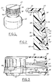
- FIGS. 3-5 illustrate closure 24 as molded, before inversion of stop flange 42, formation of score line 40 and molding of liner 32.
- a circumferential array of drain openings 52 are formed in stop flange 42 and/or band 38 during the molding operation. Drain openings 52 are disposed immediately adjacent to tamper-indicating band 38, and preferably extend radially into the inner surface of band 38, as best seen in FIG. 5.
- the walls that define the openings in flange 42 and band 38 are axially oriented and parallel to each other due to the axial orientation of the mold tooling that forms the openings. Openings 52 are entirely bounded by flange 42 and band 38. That is, drain openings 52 do not extend to the free edge 54 of stop flange 42 remote from band 38.
- drain openings 52 are rectangular, having a radial dimension of 0.060 inches and a circumferential dimension of 0.188 inches. Openings 52 extend 0.030 inches into band 38, which has a lower end thickness of 0.030 inches.
- the total radial and axial length of flange 42, measured from band 38, is 0.156 inches.
- the thickness of flange 42 adjacent to hand 38 is 0.013 to 0..015 inches, and the thickness at the free edge of the hand is 0.030 inches.
- a circumferential array of openings 60 extend radially through skirt 34.
- the array of openings 60 is disposed axially between the lower end of skirt internal thread 36 and the frangible means 40 that separate skirt 34 from band 38.
- the number of openings 60 in skirt 34 preferably is equal to the number of drain openings 52 in band 38 and/or flange 42, with one skirt through-opening 60 being disposed midway between each adjacent pair of drain openings 52.
- Each opening 60 includes a main radial portion 62 and a secondary axial portion 64. Axial portion 64 is provided for manufacturing convenience.
- each opening 60 is spaced from frangible means 40 so that, upon separation of band 38 from skirt 34 by fracture of frangible means 40, the periphery of opening 60 remains bounded by the skirt. In other words, separation at frangible means 40 does not rupture the periphery of openings 60. This prevents snagging of the edge of the skirt after the tamper-indicating band has been separated.
- a portion 66 of skirt 34 is flared radially outwardly beneath thread 36. This flared portion 66 is provided to facilitate manufacture in a compression or injection molding operation.
- Skirt through-openings 60 preferably extend radially through this flared portion 66 of skirt 34.
- openings 60 are rectangular, having a circumferential dimension of 0.126 inches and an axial dimension of 0.050 inches.
- Surface 64 has a preferred angle of 15° to the closure axis.
- the angle of flared skirt portion 66 is preferably 30° to the closure axis.
- closure 24 is either injection or compression molded as described, liner 32 is formed therein, and flange 42 is inverted to the configuration illustrated in FIG. 2.
- Container 22, which may be formed in any suitable forming operation, is filled with liquid, and closure 24 is applied thereto using conventional closure application apparatus. With the closure so applied, the closure assumes the configuration illustrated in FIG. 2.
- the container package 20 is conventionally fed through a cleansing stage, in which cleansing solution is directed onto closure 24 and the upper portion of container 22.
- cleansing solution may be performed by a circumferential array of nozzles directing water or other cleansing solution onto the container package, or by a lesser number of cleansing solution nozzles while the container package is rotated during passage through the cleansing station.
- cleansing solution freely passes through openings 60 and drain openings 52, flushing any material that may have accumulated between tamper-indicating band 38, flange 42 and container finish 26.
Abstract
Description
- The present invention relates to tamper-indicating closures, to methods of manufacturing such closures, and to a package that includes such a closure on a container.
- It is conventional to form a tamper-indicating closure having a band connected to the skirt of the closure by integral frangible bridges. The band has a stop element (e.g., a flange or bead) that engages a bead on the container to resist unthreading of the closure, so that removal of the closure ruptures the frangible bridges that connect the band to the closure skirt. U.S. Patents Re33,265, 4,322,009 and 4,432,461, assigned to the assignee hereof disclose tamper-indicating closures of this character, in which the tamper-indicating band is completely severed from the closure skirt and remains with the container upon removal of the closure from the container. U.S. Patent 5,295,600, also assigned to the assignee hereof; discloses a tamper-indicating closure in which the tamper-indicating band remains connected to the closure skirt and is removed from the container with the closure.
- Although tamper-indicating closures of the types disclosed in the noted patents have enjoyed substantial commercial acceptance and success in the art, further improvements remain desirable. In particular, it is desirable in many applications to provide facility for flushing the region between the tamper-indicating band and the container finish so as to prevent accumulation of liquid after a filling operation. For example, problems are encountered when employing this type of closure in so-called wet finish applications, in which liquid may spill during or after the filling operation onto the outside surface of the container finish so as to be disposed between the container finish and the closure skirt after capping. Wet finish situations of this type are encountered during hot-fill, cold-fill and aseptic-fill situations, in which the containers are filled close to the brim or to overflow prior to capping. Wet finish situations can also be encountered during filling operations in which liquid may drip from the filling machinery onto the container finish, in wet-finish situations of this type, problems are encountered in connection with draining and drying of the area between the outer surface of the container finish and the closure skirt - i.e., between the threads on the container finish and skirt, and around the tamper-indicating band and the stop element. Liquid trapped within this area can result in growth of mold and mildew.
- It is a general object of the present invention to provide a closure and a method of manufacturing a closure that facilitate flushing of the area between the tamper-indicating hand and the container finish during an otherwise conventional washing operation after the closure is applied to the container finish. A further object of the present invention is to provide a closure and method of manufacture that facilitate both drainage of liquid products after capping and improved air flow between the closure and container finish for drying after capping. Another and related object of the present invention is to provide a closure and method of manufacture that achieve the foregoing objectives while retaining the advantages of the closures disclosed in the above-noted patents in terms of ease of application to the container finish after filling (lower top load and lower temperature) and whole or partial rupture of the tamper-indicating band from the closure skirt to provide the tamper-indicating feature Yet another object of the present invention is to provide a package, which includes a closure and a container, that is particularly well adapted for use in conjunction with wet finish applications as described.
- A tamper-indicating closure of integrally molded plastic construction in accordance with presently a preferred embodiment of the invention includes a base wall having a peripheral skirt with internal means, such as a thread or head, for affixing the closure to the container finish. A tamper-indicating band is connected to an edge of the skirt by frangible means, such as a thin membrane or a plurality of circumferentially spaced integral frangible bridges. Stop means, such as a flange or bead, extends from an edge of the hand remote from the skirt for abutment with a bead on the container finish to inhibit removal of the closure absent fracture of the frangible means. A plurality of circumferentially spaced openings extend radially through the skirt at a position between the frangible means and the internal means. These openings provide for ingress of cleansing solution during a washing operation alter the closure is applied to a container to flush any residue from between the tamper-indicating band and the closure finish. Drain openings preferably are provided in the stop means and/or the tamper-indicating band to allow drainage of the flushing solution, and also to allow drainage of any accumulated liquid in wet-finish applications.
- The radial openings preferably extend through the skirt at a position spaced from and not intersecting the frangible means that connect the tamper-indicating band to the free edge of the skirt, such that the openings remain peripherally bounded by the skirt upon fracture of the frangible means and separation of the band from the skirt With the through-openings so bounded or surrounded by the closure skirt, the openings do not present sharp edges or burrs at the free edge of the skirt following separation of the tamper-indicating band, which might snag on anything that comes into contact with the closure skirt. In the preferred embodiment of the invention, the skirt is flared radially outwardly between the base wall and the frangible means to facilitate manufacture. The plurality of circumferentially spaced openings in the skirt extend radially through the flared portion of the skirt.
- In accordance with another aspect of the present invention, there is provided a method of making a tamper-indicating closure that comprises the step of integrally molding a closure of plastic as-molded construction that includes a base wall having a peripheral skirt with internal means for affixing the closure to a container, a tamper-indicating band connected by frangible means to an edge of the skirt, stop means extending from an edge of the band remote from the skirt for abutment with the container finish to inhibit removal of the closure absent fracture of the frangible means, and a plurality of circumferentially spaced openings that extend radially through the skirt at a position between the frangible means and the base wall, The closure is molded by injection molding or compression molding. A third aspect of the invention contemplates such a closure on a container having a finish with an external thread and an external bead for abutment with the stop means.
- A method of filling and capping a container in accordance with another aspect of the present invention includes providing a container having a finish with an external thread and an external bead. A tamper-indicating closure has a base wall, a peripheral skirt with an internal thread for engaging the external thread on the container finish, a band connected to the skirt by frangible means, a flange extending from the band for engagement with the external finish bead, and a circumferential array of openings extending through the skirt between the internal thread and the frangible means. The container is killed and the closure is applied to the container finish. Cleansing solution is then directed against the closure skirt, with a portion of such solution passing through the openings in the closure skirt to cleanse the area between the band and the container finish. The closure preferably is provided with drain openings through the band and/or the flange for facilitating drainage of such cleansing solution.
- The invention, together with additional objects, features and advantages thereof, will be best understood from the following description, the appended claims and the accompanying drawings in which:
- FIG. 1 is a fragmentary perspective view of a container and closure package in accordance with a presently preferred embodiment of the invention;
- FIG. 2 is a fragmentary sectional view that illustrates the container finish and closure in the package of FIG. 1;
- FIG. 3 is a partially sectioned side elevational view of the closure in the package of FIGS. 1 and 2 as molded - i.e., before stop flange inversion;
- FIG. 4 is a fragmentary sectional view of the portion of the closure within the circle 4 in FIG. 3; and
- FIG. 5 is a fragmentary sectional view taken substantially along the line 5-5 in FIG. 3.
-
- FIGS. 1-5 illustrate a
package 20 in accordance with one presently preferred embodiment of the invention as comprising acontainer 22 of glass or molded plastic construction and a tamper-indicatingclosure 24 threaded thereon.Container 22 has an axially extendingfinish 26 for receivingclosure 24. Closure 24 has aflat base wall 30 on which asealing liner 32 is secured. An annularperipheral skirt 34 extends downwardly fromclosure base wall 30, and has at least oneinternal thread 36 for securingclosure 24 over anexternal thread 28 ofcontainer 22. (Directional descriptions such as "downwardly' are taken with reference to the vertical orientation of the container and closure illustrated in FIGS. 1 and 2.) A tamper-indicatingband 38 is secured to the lower end ofskirt 34, being separated therefrom by acircumferential score 40. Tamper-indicatingband 38 is thus coupled toclosure skirt 34 by a circumferentially spaced array of frangible bridges. These bridges may be formed during the scoring operation, as described in the patents referenced hereinafter. Alternatively, the bridges may be molded onto the inside surface ofskirt 34 andband 38, as shown in U.S. Patents 4,407,422 and 4,418,828. Alternatively, but less preferably,band 38 may be connected toskirt 34 by a thin frangible web integrally molded with the closure. Astop flange 42 extends radially inwardly and axially upwardly (FIG. 2) from the lower inside edge ofband 38 to a position beneath a radially outwardly extendingbead 44 oncontainer 22 beneaththread 28.Bead 44 is sometimes called the container transfer bead or the "A" bead, referring to the fact thatbead 44 defines the "A" dimension of the container finish. Stopflange 42 preferably is thinnest at the connection withband 38, and thickens uniformly to the free-edge that abuts container bead 44. - Closure 24 may be injection molded as shown or compression molded as taught in U.S. Patent 5,554,327.
Liner 32 may be separately formed, or more preferably compression molded in situ within a preformed closure as disclosed in U.S. Patents 4,984,703 and 5,451,360. U.S. Patents 5,488,888, 5,522,203 and 5,564,319 disclose techniques for forming the score line and bridges in the scoring operation. U.S. Patents 5,755,347 and Re 33,265 disclose techniques for invertingstop flange 42 from the as-molded configuration of FIG. 3 to the configuration of FIG. 2 ready for use. All patents noted herein, assigned to the assignee hereof, are incorporated herein by reference for purposes of background. - FIGS. 3-5 illustrate
closure 24 as molded, before inversion ofstop flange 42, formation ofscore line 40 and molding ofliner 32. A circumferential array ofdrain openings 52 are formed instop flange 42 and/orband 38 during the molding operation.Drain openings 52 are disposed immediately adjacent to tamper-indicatingband 38, and preferably extend radially into the inner surface ofband 38, as best seen in FIG. 5. The walls that define the openings inflange 42 andband 38 are axially oriented and parallel to each other due to the axial orientation of the mold tooling that forms the openings.Openings 52 are entirely bounded byflange 42 andband 38. That is,drain openings 52 do not extend to thefree edge 54 ofstop flange 42 remote fromband 38. Rather, stop flangefree edge 54 is circumferentially continuous and disposed in a plane parallel to the plane ofclosure base wall 30 both prior to inversion (FIGS. 3-5) and after inversion (FIG. 2). In a 48 mm embodiment of the invention illustrated in FIGS. 1-5,drain openings 52 are rectangular, having a radial dimension of 0.060 inches and a circumferential dimension of 0.188 inches.Openings 52 extend 0.030 inches intoband 38, which has a lower end thickness of 0.030 inches. The total radial and axial length offlange 42, measured fromband 38, is 0.156 inches. The thickness offlange 42 adjacent tohand 38 is 0.013 to 0..015 inches, and the thickness at the free edge of the hand is 0.030 inches. - A circumferential array of
openings 60 extend radially throughskirt 34. The array ofopenings 60 is disposed axially between the lower end of skirtinternal thread 36 and the frangible means 40 thatseparate skirt 34 fromband 38. The number ofopenings 60 inskirt 34 preferably is equal to the number ofdrain openings 52 inband 38 and/orflange 42, with one skirt through-opening 60 being disposed midway between each adjacent pair ofdrain openings 52. Eachopening 60 includes a mainradial portion 62 and a secondaryaxial portion 64.Axial portion 64 is provided for manufacturing convenience. The periphery of at least the mainradial portion 62 of eachopening 60 is spaced fromfrangible means 40 so that, upon separation ofband 38 fromskirt 34 by fracture offrangible means 40, the periphery of opening 60 remains bounded by the skirt. In other words, separation atfrangible means 40 does not rupture the periphery ofopenings 60. This prevents snagging of the edge of the skirt after the tamper-indicating band has been separated. In the preferred embodiment of the invention illustrated in the drawings, aportion 66 ofskirt 34 is flared radially outwardly beneaththread 36. This flaredportion 66 is provided to facilitate manufacture in a compression or injection molding operation. Skirt through-openings 60 preferably extend radially through this flaredportion 66 ofskirt 34. In the preferred 48 mm embodiment of the invention illustrated in the drawings,openings 60 are rectangular, having a circumferential dimension of 0.126 inches and an axial dimension of 0.050 inches. There are twelve equally-spaced skirt through-openings 60 (and twelve equally-spaced drain openings 52).Surface 64 has a preferred angle of 15° to the closure axis. The angle of flaredskirt portion 66 is preferably 30° to the closure axis. - In use,
closure 24 is either injection or compression molded as described,liner 32 is formed therein, andflange 42 is inverted to the configuration illustrated in FIG. 2.Container 22, which may be formed in any suitable forming operation, is filled with liquid, andclosure 24 is applied thereto using conventional closure application apparatus. With the closure so applied, the closure assumes the configuration illustrated in FIG. 2. After filling and capping, thecontainer package 20 is conventionally fed through a cleansing stage, in which cleansing solution is directed ontoclosure 24 and the upper portion ofcontainer 22. Such cleansing may be performed by a circumferential array of nozzles directing water or other cleansing solution onto the container package, or by a lesser number of cleansing solution nozzles while the container package is rotated during passage through the cleansing station. In any event, cleansing solution freely passes throughopenings 60 anddrain openings 52, flushing any material that may have accumulated between tamper-indicatingband 38,flange 42 andcontainer finish 26.
Claims (14)
- A tamper-indicating closure (24) of integrally molded plastic construction, which includes a base wall (30) having a peripheral skirt (34) with internal means (36) for affixing the closure to a container, a tamper-indicating band (38) connected by frangible means (40) to an edge of said skirt a portion (66) of said skirt being flared radially outwardly between said base wall and said frangible means, and a stop flange (42) extending axially and radially from an edge of said band remote from said skirt for abutment with a container to inhibit removal of the closure absent fracture of said frangible means,
characterized in that a plurality of circumferentially spaced openings (60) extend radially through said flared portion of said skirt at a position between said frangible means and said base wall, and in that a plurality of circumferentially spaced openings (52) extend axially through said band adjacent to said flange, through said flange adjacent to said band, or through both said flange and said band. - The closure set forth in claim 1 wherein said radially extending openings (60) extend through said skirt at a position spaced from and not intersecting said frangible means (40), such that said openings remain peripherally bounded by said skirt upon fracture of said frangible means and separation of said band (38) from said skirt (34).
- The closure set forth in claim 2 wherein said means (36) for affixing the closure to a container comprises an internal thread integrally molded within said skirt (34), and wherein said radially extending openings (60) are disposed between said thread and said frangible means (40).
- The closure set forth in claim 3 wherein said radially extending openings (60) are equal in number to said axially extending openings (52), and wherein said radial openings (60) and said axial openings (52) are circumferentially staggered around said skirt (38).
- The closure set forth in claim 4 wherein said radially extending openings (60) and said axially extending openings (52) are substantially rectangular in geometry.
- The closure set forth in claim 5 wherein said axially extending openings (52) are larger than said radially extending openings (60).
- The closure set forth in claim 3 in combination with a container (22) having a finish (26) with an external thread (28) to which said internal thread (36) is secured and an external bead (44) engaged by said stop flange (42).
- A method of making a tamper-indicating closure that includes the step of:integrally molding a closure (24) of plastic as-molded construction that includes a base wall (30) having a peripheral skirt (34) with internal means (36) for affixing the closure to a container, a tamper-indicating band (38) connected by frangible means (40) to an edge of said skirt, a portion (66) of said skirt being flared radially outwardly between said base wall and said frangible means, a stop flange (42) extending axially and radially from an edge of said band remote from said skirt for abutment with a container to inhibit removal of the closure absent fracture of said frangible means, a plurality of circumferentially spaced openings (60) extending radially through said flared portion of said skirt at a position between said frangible means and said base wall, and a plurality of circumferentially spaced openings (52) extending axially through said band adjacent to said flange, through said flange adjacent to said band, or through both said flange and said band.
- The method set forth in claim 8 wherein said step of molding said closure is selected from the group consisting of injection molding said closure and compression molding said closure.
- The method set forth in claim 8 wherein said radially extending openings extend through said skirt at a position spaced from and not intersecting said frangible means, such that said openings remain peripherally bounded by said skirt upon fracture of said frangible means and separation of said band from said skirt.
- The method set forth in claim 10 wherein said means for affixing the closure to a container comprises an internal thread integrally molded within said skirt, and wherein said radially extending openings are disposed between said thread and said frangible means.
- The method set forth in claim 11 wherein said radially extending openings (60) are equal in number to said axially extending openings (52), and wherein said radial openings (60) and said axial openings (52) are circumferentially staggered around said skirt (38).
- The closure set forth in claim 12 wherein said radially extending openings (60) and said axially extending openings (52) are substantially rectangular in geometry.
- The closure set forth in claim 13 wherein said axially extending openings (52) are larger than said radially extending openings (60).
Applications Claiming Priority (2)
| Application Number | Priority Date | Filing Date | Title |
|---|---|---|---|
| US301282 | 1999-04-28 | ||
| US09/301,282 US6253940B1 (en) | 1999-04-28 | 1999-04-28 | Tamper-indicating closure and method of manufacture |
Publications (3)
| Publication Number | Publication Date |
|---|---|
| EP1048584A2 true EP1048584A2 (en) | 2000-11-02 |
| EP1048584A3 EP1048584A3 (en) | 2002-08-14 |
| EP1048584B1 EP1048584B1 (en) | 2007-05-30 |
Family
ID=23162707
Family Applications (1)
| Application Number | Title | Priority Date | Filing Date |
|---|---|---|---|
| EP00303385A Expired - Lifetime EP1048584B1 (en) | 1999-04-28 | 2000-04-20 | Tamper indicating closure and method of manufacture |
Country Status (14)
| Country | Link |
|---|---|
| US (1) | US6253940B1 (en) |
| EP (1) | EP1048584B1 (en) |
| JP (1) | JP3600506B2 (en) |
| CN (1) | CN1271680A (en) |
| AR (1) | AR023766A1 (en) |
| AT (1) | ATE363438T1 (en) |
| AU (1) | AU756654B2 (en) |
| BR (1) | BR0002135A (en) |
| CA (1) | CA2306084C (en) |
| DE (1) | DE60034988T2 (en) |
| EE (1) | EE200000274A (en) |
| HU (1) | HU0001598D0 (en) |
| MX (1) | MXPA00003988A (en) |
| PL (1) | PL339892A1 (en) |
Cited By (1)
| Publication number | Priority date | Publication date | Assignee | Title |
|---|---|---|---|---|
| US6659297B2 (en) | 2001-11-28 | 2003-12-09 | Owens-Illinois Closure Inc. | Tamper-indicating closure, container, package and methods of manufacture |
Families Citing this family (27)
| Publication number | Priority date | Publication date | Assignee | Title |
|---|---|---|---|---|
| US6382443B1 (en) | 1999-04-28 | 2002-05-07 | Owens-Illinois Closure Inc. | Tamper-indicating closure with lugs on a stop flange for spacing the flange from the finish of a container |
| US6355201B1 (en) * | 2000-09-07 | 2002-03-12 | Captive Plastics, Inc. | Tamper-indicating closure with resilient locking projections |
| US7168581B2 (en) | 2001-12-21 | 2007-01-30 | Rexam Medical Packaging Inc. | Closure for a retort processed container having a peelable seal |
| US6948630B2 (en) * | 2001-12-21 | 2005-09-27 | Rexam Medical Packaging, Inc. | Self-draining container neck and closure |
| NL1019903C2 (en) * | 2002-02-05 | 2003-08-07 | Itsac Nv | Collar screwable on a neck of a holder. |
| US6974046B2 (en) * | 2002-02-14 | 2005-12-13 | Crown Cork & Seal Technologies Corporation | Tamper evident closure with integrated venting and method of manufacturing |
| CA2419086A1 (en) | 2002-02-22 | 2003-08-22 | Owens-Illinois Closure Inc. | Tamper-indicating closure and package |
| US20040040928A1 (en) * | 2002-09-04 | 2004-03-04 | Alto Plastics Limited | Retained satellite ring cap and bottle assembly |
| US7644902B1 (en) | 2003-05-31 | 2010-01-12 | Rexam Medical Packaging Inc. | Apparatus for producing a retort thermal processed container with a peelable seal |
| CN101005997A (en) * | 2004-06-18 | 2007-07-25 | 希尔康白帽美国有限公司 | Composite closure with barrier end panel |
| US7798359B1 (en) | 2004-08-17 | 2010-09-21 | Momar Industries LLC | Heat-sealed, peelable lidding membrane for retort packaging |
| JP4759295B2 (en) * | 2005-03-22 | 2011-08-31 | 日本クラウンコルク株式会社 | Plastic cap |
| US20080190882A1 (en) * | 2005-04-28 | 2008-08-14 | Matthew Eric Smith | Beverage Containers |
| US7780024B1 (en) | 2005-07-14 | 2010-08-24 | Rexam Closures And Containers Inc. | Self peel flick-it seal for an opening in a container neck |
| US8100277B1 (en) | 2005-07-14 | 2012-01-24 | Rexam Closures And Containers Inc. | Peelable seal for an opening in a container neck |
| JP2009522179A (en) * | 2005-12-28 | 2009-06-11 | シルガン・ホワイト・キャップ・アメリカズ・エルエルシー | Retort package with plastic closure cap |
| TWI386347B (en) * | 2006-09-15 | 2013-02-21 | Carbonite Corp | Beverage containers |
| US8251236B1 (en) | 2007-11-02 | 2012-08-28 | Berry Plastics Corporation | Closure with lifting mechanism |
| IT1403338B1 (en) * | 2010-12-21 | 2013-10-17 | Sacmi | SCREW CAP |
| IT1403710B1 (en) * | 2010-12-21 | 2013-10-31 | Sacmi | SCREW CAP |
| DE102011014886B3 (en) * | 2011-03-23 | 2011-12-15 | Alfelder Kunststoffwerke Herm. Meyer Gmbh | Container e.g. bottle, for holding e.g. engine oil, has closure comprising sealing disk for closing opening, where sealing disk is provided with fluorescent pigment such that existence of pigment is detectable with sensors |
| CN103857599B (en) * | 2011-09-14 | 2016-10-26 | 日本山村硝子株式会社 | Lid and container |
| WO2014015342A1 (en) * | 2012-07-20 | 2014-01-23 | Closure Systems International Inc. | Lightweight closure and container package |
| GB201601789D0 (en) * | 2016-02-01 | 2016-03-16 | Obrist Closures Switzerland | Improvements in or relating to tamper-evident closures |
| IT201900011124A1 (en) * | 2019-07-08 | 2021-01-08 | Sacmi | Cap to close a container. |
| US11059633B2 (en) | 2019-10-31 | 2021-07-13 | Cheer Pack North America | Flip-top closure for container |
| US20220097935A1 (en) * | 2020-09-28 | 2022-03-31 | Closure Systems International Inc. | Package and closure with tamper-evident band |
Citations (12)
| Publication number | Priority date | Publication date | Assignee | Title |
|---|---|---|---|---|
| US4322009A (en) | 1980-05-19 | 1982-03-30 | Owens-Illinois, Inc. | Tamper proof molded plastic closure |
| US4407422A (en) | 1981-06-04 | 1983-10-04 | H-C Industries, Inc. | Composite closure |
| US4418828A (en) | 1981-07-24 | 1983-12-06 | H-C Industries, Inc. | Plastic closure with mechanical pilfer band |
| US4432461A (en) | 1982-04-09 | 1984-02-21 | Owens-Illinois, Inc. | Tamper indicating package |
| USRE33265E (en) | 1985-04-29 | 1990-07-17 | Owens-Illinois Closure Inc. | Tamper-indicating closure, container and combination thereof |
| US4984703A (en) | 1989-10-03 | 1991-01-15 | Owens-Illinois Closure Inc. | Plastic closure with compression molded sealing liner |
| US5295600A (en) | 1993-02-25 | 1994-03-22 | Owens-Illinois Closure Inc. | Tamper indicating closure |
| US5451360A (en) | 1993-10-14 | 1995-09-19 | Owens-Illinois Closure Inc. | Method and apparatus for compression molding closure liners |
| US5488888A (en) | 1993-04-19 | 1996-02-06 | Owens-Illinois Closure Inc. | Method of forming bridges in tamper indicating closures |
| US5522203A (en) | 1990-10-02 | 1996-06-04 | Lantech, Inc. | Biaxial stretch wrapping |
| US5554327A (en) | 1993-10-14 | 1996-09-10 | Owens-Illinois Closure Inc. | Method and apparatus for compression molding plastic articles |
| US5755347A (en) | 1989-07-27 | 1998-05-26 | Owens-Illinois Closure Inc. | Tamper indicating package |
Family Cites Families (20)
| Publication number | Priority date | Publication date | Assignee | Title |
|---|---|---|---|---|
| FR2439140A1 (en) * | 1978-10-17 | 1980-05-16 | Bouchons Plastiques | Screwed-on security cap for bottle - has locking ring moulded on and folded back inside cap rim |
| US4573601A (en) | 1983-06-01 | 1986-03-04 | Wicanders Ab | Screw cap with security ring |
| US4552328A (en) | 1984-01-05 | 1985-11-12 | Sun Coast Plastics, Inc. | Mold for making tamper-proof closure |
| US4560076A (en) * | 1984-04-17 | 1985-12-24 | Continental White Cap, Inc. | Tamper indicating band for use in low rise cam-off application |
| US4625875A (en) | 1985-02-04 | 1986-12-02 | Carr Joseph J | Tamper-evident closure |
| US4572388A (en) * | 1985-03-18 | 1986-02-25 | Sunbeam Plastics Corporation | Tamper indicating screw cap |
| US4611723A (en) * | 1985-10-15 | 1986-09-16 | William Megowen | Container closure with expandable anti-missiling section |
| US4657153A (en) * | 1985-11-18 | 1987-04-14 | Anchor Hocking Corporation | Tamper-evident closure |
| IL89091A (en) | 1988-02-16 | 1994-06-24 | Aichinger Dietmar F | Closure for container and a tool for its manufacture |
| US4978016A (en) * | 1989-09-01 | 1990-12-18 | Anchor Hocking Corporation | Tamper indicating closure having retaining hoop with relief windows |
| US5080246A (en) * | 1989-09-01 | 1992-01-14 | Anchor Hocking Packaging Company | Closure having a spring open tamper evidencing band |
| US5058755A (en) * | 1989-09-01 | 1991-10-22 | Anchor Hocking Packaging Company | Tamper indicating closure having retaining hoop with relief windows |
| US4981230A (en) * | 1990-03-15 | 1991-01-01 | Continental White Cap, Inc. | Composite cap including tamper indicating band |
| US5443853A (en) * | 1991-05-01 | 1995-08-22 | Anchor Hocking Packaging Co. | Press-on, pry-off closure for microwavable vacuum sealed container |
| US5107998A (en) | 1991-06-14 | 1992-04-28 | Bruno Zumbuhl | Tamper proof ring for threaded closures |
| US5913436A (en) * | 1995-02-11 | 1999-06-22 | Safety Cap System Ag | Screw cap, specifically comprised of plastic, for closing a bottle or the like |
| US5685443A (en) | 1995-03-06 | 1997-11-11 | White Cap, Inc. | Composite closure and method of making same |
| US5660290A (en) * | 1996-03-27 | 1997-08-26 | Carnaudmetalbox (Holdings) Usa Inc. | Closure fitting for unthreaded containers |
| JP3136109B2 (en) | 1996-11-22 | 2001-02-19 | 日本山村硝子株式会社 | Synthetic resin cap and manufacturing method thereof |
| US5971182A (en) * | 1998-05-18 | 1999-10-26 | Creative Packaging Corp. | Closure with tamper-evident band |
-
1999
- 1999-04-28 US US09/301,282 patent/US6253940B1/en not_active Expired - Fee Related
-
2000
- 2000-04-18 CA CA002306084A patent/CA2306084C/en not_active Expired - Fee Related
- 2000-04-19 HU HU0001598A patent/HU0001598D0/en unknown
- 2000-04-20 EP EP00303385A patent/EP1048584B1/en not_active Expired - Lifetime
- 2000-04-20 AT AT00303385T patent/ATE363438T1/en not_active IP Right Cessation
- 2000-04-20 DE DE60034988T patent/DE60034988T2/en not_active Expired - Lifetime
- 2000-04-25 MX MXPA00003988A patent/MXPA00003988A/en active IP Right Grant
- 2000-04-25 AR ARP000101938A patent/AR023766A1/en unknown
- 2000-04-26 EE EEP200000274A patent/EE200000274A/en unknown
- 2000-04-26 PL PL00339892A patent/PL339892A1/en not_active IP Right Cessation
- 2000-04-27 BR BR0002135-0A patent/BR0002135A/en not_active Application Discontinuation
- 2000-04-28 JP JP2000130497A patent/JP3600506B2/en not_active Expired - Lifetime
- 2000-04-28 CN CN00107087.8A patent/CN1271680A/en active Pending
- 2000-04-28 AU AU30188/00A patent/AU756654B2/en not_active Ceased
Patent Citations (13)
| Publication number | Priority date | Publication date | Assignee | Title |
|---|---|---|---|---|
| US4322009A (en) | 1980-05-19 | 1982-03-30 | Owens-Illinois, Inc. | Tamper proof molded plastic closure |
| US4407422A (en) | 1981-06-04 | 1983-10-04 | H-C Industries, Inc. | Composite closure |
| US4418828A (en) | 1981-07-24 | 1983-12-06 | H-C Industries, Inc. | Plastic closure with mechanical pilfer band |
| US4432461A (en) | 1982-04-09 | 1984-02-21 | Owens-Illinois, Inc. | Tamper indicating package |
| USRE33265E (en) | 1985-04-29 | 1990-07-17 | Owens-Illinois Closure Inc. | Tamper-indicating closure, container and combination thereof |
| US5755347A (en) | 1989-07-27 | 1998-05-26 | Owens-Illinois Closure Inc. | Tamper indicating package |
| US4984703A (en) | 1989-10-03 | 1991-01-15 | Owens-Illinois Closure Inc. | Plastic closure with compression molded sealing liner |
| US5522203A (en) | 1990-10-02 | 1996-06-04 | Lantech, Inc. | Biaxial stretch wrapping |
| US5295600A (en) | 1993-02-25 | 1994-03-22 | Owens-Illinois Closure Inc. | Tamper indicating closure |
| US5488888A (en) | 1993-04-19 | 1996-02-06 | Owens-Illinois Closure Inc. | Method of forming bridges in tamper indicating closures |
| US5564319A (en) | 1993-04-19 | 1996-10-15 | Owens-Illinois Closure Inc. | Apparatus for forming bridges in tamper indicating closures |
| US5451360A (en) | 1993-10-14 | 1995-09-19 | Owens-Illinois Closure Inc. | Method and apparatus for compression molding closure liners |
| US5554327A (en) | 1993-10-14 | 1996-09-10 | Owens-Illinois Closure Inc. | Method and apparatus for compression molding plastic articles |
Cited By (3)
| Publication number | Priority date | Publication date | Assignee | Title |
|---|---|---|---|---|
| US6659297B2 (en) | 2001-11-28 | 2003-12-09 | Owens-Illinois Closure Inc. | Tamper-indicating closure, container, package and methods of manufacture |
| EP1316507A3 (en) * | 2001-11-28 | 2004-01-02 | Owens-Illinois Closure Inc. | Tamper-indicating closure and container with drain elements and methods of manufacture |
| US7235207B2 (en) | 2001-11-28 | 2007-06-26 | Owens-Illinois Closure Inc. | Method of making a tamper-indicating closure |
Also Published As
| Publication number | Publication date |
|---|---|
| JP3600506B2 (en) | 2004-12-15 |
| MXPA00003988A (en) | 2002-03-08 |
| ATE363438T1 (en) | 2007-06-15 |
| AU3018800A (en) | 2000-11-02 |
| EE200000274A (en) | 2000-12-15 |
| PL339892A1 (en) | 2000-11-06 |
| CA2306084C (en) | 2006-08-15 |
| US6253940B1 (en) | 2001-07-03 |
| BR0002135A (en) | 2000-11-21 |
| DE60034988T2 (en) | 2008-01-31 |
| DE60034988D1 (en) | 2007-07-12 |
| AU756654B2 (en) | 2003-01-16 |
| CA2306084A1 (en) | 2000-10-28 |
| EP1048584B1 (en) | 2007-05-30 |
| CN1271680A (en) | 2000-11-01 |
| JP2000318753A (en) | 2000-11-21 |
| HU0001598D0 (en) | 2000-06-28 |
| EP1048584A3 (en) | 2002-08-14 |
| AR023766A1 (en) | 2002-09-04 |
Similar Documents
| Publication | Publication Date | Title |
|---|---|---|
| US6253940B1 (en) | Tamper-indicating closure and method of manufacture | |
| US6119883A (en) | Tamper-indicating closure and method of manufacture | |
| JP3655167B2 (en) | Unauthorized operation instruction closure and manufacturing method | |
| US6382443B1 (en) | Tamper-indicating closure with lugs on a stop flange for spacing the flange from the finish of a container | |
| US6659297B2 (en) | Tamper-indicating closure, container, package and methods of manufacture | |
| KR100436168B1 (en) | Opening check with stop band | |
| US6766916B2 (en) | Tamper evidencing closure | |
| CA1160180A (en) | Tamper proof closure | |
| US5891380A (en) | Tamper evident caps and methods | |
| HU218169B (en) | Cap for bottles, bottle with cap, and process and tool for production of the cap | |
| EP0262868B1 (en) | Guarantee band for a container closure | |
| MXPA99011275A (en) | Inviolable closure and my manufacturing method | |
| MXPA97007176A (en) | Inviolable closure with band caut |
Legal Events
| Date | Code | Title | Description |
|---|---|---|---|
| PUAI | Public reference made under article 153(3) epc to a published international application that has entered the european phase |
Free format text: ORIGINAL CODE: 0009012 |
|
| AK | Designated contracting states |
Kind code of ref document: A2 Designated state(s): AT BE CH CY DE DK ES FI FR GB GR IE IT LI LU MC NL PT SE |
|
| AX | Request for extension of the european patent |
Free format text: AL;LT;LV;MK;RO;SI |
|
| PUAL | Search report despatched |
Free format text: ORIGINAL CODE: 0009013 |
|
| AK | Designated contracting states |
Kind code of ref document: A3 Designated state(s): AT BE CH CY DE DK ES FI FR GB GR IE IT LI LU MC NL PT SE |
|
| AX | Request for extension of the european patent |
Free format text: AL;LT;LV;MK;RO;SI |
|
| 17P | Request for examination filed |
Effective date: 20030123 |
|
| AKX | Designation fees paid |
Designated state(s): AT BE CH CY DE DK ES FI FR GB GR IE IT LI LU MC NL PT SE |
|
| 17Q | First examination report despatched |
Effective date: 20050228 |
|
| GRAP | Despatch of communication of intention to grant a patent |
Free format text: ORIGINAL CODE: EPIDOSNIGR1 |
|
| RAP1 | Party data changed (applicant data changed or rights of an application transferred) |
Owner name: OWENS-ILLINOIS CLOSURE, INC. |
|
| GRAS | Grant fee paid |
Free format text: ORIGINAL CODE: EPIDOSNIGR3 |
|
| GRAA | (expected) grant |
Free format text: ORIGINAL CODE: 0009210 |
|
| AK | Designated contracting states |
Kind code of ref document: B1 Designated state(s): AT BE CH CY DE DK ES FI FR GB GR IE IT LI LU MC NL PT SE |
|
| PG25 | Lapsed in a contracting state [announced via postgrant information from national office to epo] |
Ref country code: FI Free format text: LAPSE BECAUSE OF FAILURE TO SUBMIT A TRANSLATION OF THE DESCRIPTION OR TO PAY THE FEE WITHIN THE PRESCRIBED TIME-LIMIT Effective date: 20070530 Ref country code: LI Free format text: LAPSE BECAUSE OF FAILURE TO SUBMIT A TRANSLATION OF THE DESCRIPTION OR TO PAY THE FEE WITHIN THE PRESCRIBED TIME-LIMIT Effective date: 20070530 Ref country code: CH Free format text: LAPSE BECAUSE OF FAILURE TO SUBMIT A TRANSLATION OF THE DESCRIPTION OR TO PAY THE FEE WITHIN THE PRESCRIBED TIME-LIMIT Effective date: 20070530 |
|
| REG | Reference to a national code |
Ref country code: GB Ref legal event code: FG4D |
|
| REG | Reference to a national code |
Ref country code: CH Ref legal event code: EP |
|
| REG | Reference to a national code |
Ref country code: IE Ref legal event code: FG4D |
|
| REF | Corresponds to: |
Ref document number: 60034988 Country of ref document: DE Date of ref document: 20070712 Kind code of ref document: P |
|
| PG25 | Lapsed in a contracting state [announced via postgrant information from national office to epo] |
Ref country code: SE Free format text: LAPSE BECAUSE OF FAILURE TO SUBMIT A TRANSLATION OF THE DESCRIPTION OR TO PAY THE FEE WITHIN THE PRESCRIBED TIME-LIMIT Effective date: 20070830 |
|
| PG25 | Lapsed in a contracting state [announced via postgrant information from national office to epo] |
Ref country code: ES Free format text: LAPSE BECAUSE OF FAILURE TO SUBMIT A TRANSLATION OF THE DESCRIPTION OR TO PAY THE FEE WITHIN THE PRESCRIBED TIME-LIMIT Effective date: 20070910 |
|
| ET | Fr: translation filed | ||
| PG25 | Lapsed in a contracting state [announced via postgrant information from national office to epo] |
Ref country code: AT Free format text: LAPSE BECAUSE OF FAILURE TO SUBMIT A TRANSLATION OF THE DESCRIPTION OR TO PAY THE FEE WITHIN THE PRESCRIBED TIME-LIMIT Effective date: 20070530 |
|
| NLV1 | Nl: lapsed or annulled due to failure to fulfill the requirements of art. 29p and 29m of the patents act | ||
| REG | Reference to a national code |
Ref country code: CH Ref legal event code: PL |
|
| PG25 | Lapsed in a contracting state [announced via postgrant information from national office to epo] |
Ref country code: BE Free format text: LAPSE BECAUSE OF FAILURE TO SUBMIT A TRANSLATION OF THE DESCRIPTION OR TO PAY THE FEE WITHIN THE PRESCRIBED TIME-LIMIT Effective date: 20070530 |
|
| PG25 | Lapsed in a contracting state [announced via postgrant information from national office to epo] |
Ref country code: DK Free format text: LAPSE BECAUSE OF FAILURE TO SUBMIT A TRANSLATION OF THE DESCRIPTION OR TO PAY THE FEE WITHIN THE PRESCRIBED TIME-LIMIT Effective date: 20070530 Ref country code: PT Free format text: LAPSE BECAUSE OF FAILURE TO SUBMIT A TRANSLATION OF THE DESCRIPTION OR TO PAY THE FEE WITHIN THE PRESCRIBED TIME-LIMIT Effective date: 20071030 Ref country code: NL Free format text: LAPSE BECAUSE OF FAILURE TO SUBMIT A TRANSLATION OF THE DESCRIPTION OR TO PAY THE FEE WITHIN THE PRESCRIBED TIME-LIMIT Effective date: 20070530 |
|
| PLBE | No opposition filed within time limit |
Free format text: ORIGINAL CODE: 0009261 |
|
| STAA | Information on the status of an ep patent application or granted ep patent |
Free format text: STATUS: NO OPPOSITION FILED WITHIN TIME LIMIT |
|
| PG25 | Lapsed in a contracting state [announced via postgrant information from national office to epo] |
Ref country code: IT Free format text: LAPSE BECAUSE OF FAILURE TO SUBMIT A TRANSLATION OF THE DESCRIPTION OR TO PAY THE FEE WITHIN THE PRESCRIBED TIME-LIMIT Effective date: 20070530 Ref country code: GR Free format text: LAPSE BECAUSE OF FAILURE TO SUBMIT A TRANSLATION OF THE DESCRIPTION OR TO PAY THE FEE WITHIN THE PRESCRIBED TIME-LIMIT Effective date: 20070831 |
|
| 26N | No opposition filed |
Effective date: 20080303 |
|
| REG | Reference to a national code |
Ref country code: FR Ref legal event code: CA Ref country code: FR Ref legal event code: CD |
|
| PG25 | Lapsed in a contracting state [announced via postgrant information from national office to epo] |
Ref country code: MC Free format text: LAPSE BECAUSE OF NON-PAYMENT OF DUE FEES Effective date: 20080430 |
|
| GBPC | Gb: european patent ceased through non-payment of renewal fee |
Effective date: 20080420 |
|
| PG25 | Lapsed in a contracting state [announced via postgrant information from national office to epo] |
Ref country code: IE Free format text: LAPSE BECAUSE OF NON-PAYMENT OF DUE FEES Effective date: 20080421 |
|
| PG25 | Lapsed in a contracting state [announced via postgrant information from national office to epo] |
Ref country code: GB Free format text: LAPSE BECAUSE OF NON-PAYMENT OF DUE FEES Effective date: 20080420 |
|
| PG25 | Lapsed in a contracting state [announced via postgrant information from national office to epo] |
Ref country code: CY Free format text: LAPSE BECAUSE OF FAILURE TO SUBMIT A TRANSLATION OF THE DESCRIPTION OR TO PAY THE FEE WITHIN THE PRESCRIBED TIME-LIMIT Effective date: 20070530 |
|
| PG25 | Lapsed in a contracting state [announced via postgrant information from national office to epo] |
Ref country code: LU Free format text: LAPSE BECAUSE OF NON-PAYMENT OF DUE FEES Effective date: 20080420 |
|
| PGFP | Annual fee paid to national office [announced via postgrant information from national office to epo] |
Ref country code: DE Payment date: 20120427 Year of fee payment: 13 |
|
| PGFP | Annual fee paid to national office [announced via postgrant information from national office to epo] |
Ref country code: FR Payment date: 20120503 Year of fee payment: 13 |
|
| PG25 | Lapsed in a contracting state [announced via postgrant information from national office to epo] |
Ref country code: DE Free format text: LAPSE BECAUSE OF NON-PAYMENT OF DUE FEES Effective date: 20131101 |
|
| REG | Reference to a national code |
Ref country code: FR Ref legal event code: ST Effective date: 20131231 |
|
| REG | Reference to a national code |
Ref country code: DE Ref legal event code: R119 Ref document number: 60034988 Country of ref document: DE Effective date: 20131101 |
|
| PG25 | Lapsed in a contracting state [announced via postgrant information from national office to epo] |
Ref country code: FR Free format text: LAPSE BECAUSE OF NON-PAYMENT OF DUE FEES Effective date: 20130430 |