EP1050264B1 - Implantable acoustic bio-sensing system and method - Google Patents
Implantable acoustic bio-sensing system and method Download PDFInfo
- Publication number
- EP1050264B1 EP1050264B1 EP00109256A EP00109256A EP1050264B1 EP 1050264 B1 EP1050264 B1 EP 1050264B1 EP 00109256 A EP00109256 A EP 00109256A EP 00109256 A EP00109256 A EP 00109256A EP 1050264 B1 EP1050264 B1 EP 1050264B1
- Authority
- EP
- European Patent Office
- Prior art keywords
- sensor
- acoustic
- transducer
- patient
- electrical
- Prior art date
- Legal status (The legal status is an assumption and is not a legal conclusion. Google has not performed a legal analysis and makes no representation as to the accuracy of the status listed.)
- Expired - Lifetime
Links
- 238000000034 method Methods 0.000 title description 11
- 230000004962 physiological condition Effects 0.000 claims abstract description 50
- 238000012544 monitoring process Methods 0.000 claims abstract description 32
- 239000008280 blood Substances 0.000 claims description 8
- 210000004369 blood Anatomy 0.000 claims description 8
- 239000002033 PVDF binder Substances 0.000 claims description 6
- 229920002981 polyvinylidene fluoride Polymers 0.000 claims description 6
- 230000005855 radiation Effects 0.000 claims description 6
- 230000001133 acceleration Effects 0.000 claims description 4
- QVGXLLKOCUKJST-UHFFFAOYSA-N atomic oxygen Chemical compound [O] QVGXLLKOCUKJST-UHFFFAOYSA-N 0.000 claims description 4
- 230000005672 electromagnetic field Effects 0.000 claims description 4
- 230000002255 enzymatic effect Effects 0.000 claims description 4
- 239000000463 material Substances 0.000 claims description 4
- 239000001301 oxygen Substances 0.000 claims description 4
- 229910052760 oxygen Inorganic materials 0.000 claims description 4
- 239000000126 substance Substances 0.000 claims description 4
- 210000004027 cell Anatomy 0.000 description 24
- 230000007246 mechanism Effects 0.000 description 20
- 210000004556 brain Anatomy 0.000 description 19
- 230000004044 response Effects 0.000 description 19
- 210000001175 cerebrospinal fluid Anatomy 0.000 description 18
- 239000000758 substrate Substances 0.000 description 16
- 238000006073 displacement reaction Methods 0.000 description 14
- 239000012530 fluid Substances 0.000 description 14
- 238000012806 monitoring device Methods 0.000 description 14
- 230000002463 transducing effect Effects 0.000 description 13
- 238000007917 intracranial administration Methods 0.000 description 9
- 230000005540 biological transmission Effects 0.000 description 7
- 238000010276 construction Methods 0.000 description 6
- 238000012545 processing Methods 0.000 description 5
- XLYOFNOQVPJJNP-UHFFFAOYSA-N water Substances O XLYOFNOQVPJJNP-UHFFFAOYSA-N 0.000 description 5
- 230000008901 benefit Effects 0.000 description 4
- 230000008859 change Effects 0.000 description 4
- 230000000694 effects Effects 0.000 description 4
- 208000003906 hydrocephalus Diseases 0.000 description 4
- 230000035945 sensitivity Effects 0.000 description 4
- 238000001356 surgical procedure Methods 0.000 description 4
- 230000002861 ventricular Effects 0.000 description 4
- XUIMIQQOPSSXEZ-UHFFFAOYSA-N Silicon Chemical compound [Si] XUIMIQQOPSSXEZ-UHFFFAOYSA-N 0.000 description 3
- 230000003213 activating effect Effects 0.000 description 3
- 230000008878 coupling Effects 0.000 description 3
- 238000010168 coupling process Methods 0.000 description 3
- 238000005859 coupling reaction Methods 0.000 description 3
- 230000003247 decreasing effect Effects 0.000 description 3
- 238000005516 engineering process Methods 0.000 description 3
- 239000007789 gas Substances 0.000 description 3
- 239000007943 implant Substances 0.000 description 3
- 238000002513 implantation Methods 0.000 description 3
- 230000010354 integration Effects 0.000 description 3
- 229920000642 polymer Polymers 0.000 description 3
- 238000007789 sealing Methods 0.000 description 3
- 229910052710 silicon Inorganic materials 0.000 description 3
- 239000010703 silicon Substances 0.000 description 3
- 210000003625 skull Anatomy 0.000 description 3
- 230000003068 static effect Effects 0.000 description 3
- 238000010521 absorption reaction Methods 0.000 description 2
- 230000003321 amplification Effects 0.000 description 2
- 230000003750 conditioning effect Effects 0.000 description 2
- 238000013461 design Methods 0.000 description 2
- 238000010586 diagram Methods 0.000 description 2
- 238000009826 distribution Methods 0.000 description 2
- 238000005259 measurement Methods 0.000 description 2
- 239000012528 membrane Substances 0.000 description 2
- 238000012986 modification Methods 0.000 description 2
- 230000004048 modification Effects 0.000 description 2
- 238000003199 nucleic acid amplification method Methods 0.000 description 2
- 238000005457 optimization Methods 0.000 description 2
- 210000001519 tissue Anatomy 0.000 description 2
- 238000002834 transmittance Methods 0.000 description 2
- 238000002604 ultrasonography Methods 0.000 description 2
- RYGMFSIKBFXOCR-UHFFFAOYSA-N Copper Chemical compound [Cu] RYGMFSIKBFXOCR-UHFFFAOYSA-N 0.000 description 1
- 239000004642 Polyimide Substances 0.000 description 1
- 210000001015 abdomen Anatomy 0.000 description 1
- 210000000683 abdominal cavity Anatomy 0.000 description 1
- 230000002159 abnormal effect Effects 0.000 description 1
- 239000000956 alloy Substances 0.000 description 1
- 229910045601 alloy Inorganic materials 0.000 description 1
- 239000003990 capacitor Substances 0.000 description 1
- 238000006243 chemical reaction Methods 0.000 description 1
- 238000004891 communication Methods 0.000 description 1
- 230000006835 compression Effects 0.000 description 1
- 238000007906 compression Methods 0.000 description 1
- 229920001577 copolymer Polymers 0.000 description 1
- 229910052802 copper Inorganic materials 0.000 description 1
- 239000010949 copper Substances 0.000 description 1
- 230000007423 decrease Effects 0.000 description 1
- 230000005611 electricity Effects 0.000 description 1
- 238000005530 etching Methods 0.000 description 1
- 238000011156 evaluation Methods 0.000 description 1
- 230000005284 excitation Effects 0.000 description 1
- 238000001914 filtration Methods 0.000 description 1
- 230000002706 hydrostatic effect Effects 0.000 description 1
- 229910052738 indium Inorganic materials 0.000 description 1
- APFVFJFRJDLVQX-UHFFFAOYSA-N indium atom Chemical compound [In] APFVFJFRJDLVQX-UHFFFAOYSA-N 0.000 description 1
- 208000015181 infectious disease Diseases 0.000 description 1
- 238000004519 manufacturing process Methods 0.000 description 1
- 239000011159 matrix material Substances 0.000 description 1
- 238000004377 microelectronic Methods 0.000 description 1
- 238000005459 micromachining Methods 0.000 description 1
- 239000012811 non-conductive material Substances 0.000 description 1
- 210000000056 organ Anatomy 0.000 description 1
- 238000010422 painting Methods 0.000 description 1
- 230000000737 periodic effect Effects 0.000 description 1
- 238000000206 photolithography Methods 0.000 description 1
- 230000000704 physical effect Effects 0.000 description 1
- 229920001721 polyimide Polymers 0.000 description 1
- 230000009467 reduction Effects 0.000 description 1
- 238000009877 rendering Methods 0.000 description 1
- 238000007920 subcutaneous administration Methods 0.000 description 1
- 229920003002 synthetic resin Polymers 0.000 description 1
- 239000000057 synthetic resin Substances 0.000 description 1
- 238000012360 testing method Methods 0.000 description 1
- 230000036962 time dependent Effects 0.000 description 1
- 230000001052 transient effect Effects 0.000 description 1
- 230000001960 triggered effect Effects 0.000 description 1
- 238000001771 vacuum deposition Methods 0.000 description 1
Images


Classifications
-
- A—HUMAN NECESSITIES
- A61—MEDICAL OR VETERINARY SCIENCE; HYGIENE
- A61B—DIAGNOSIS; SURGERY; IDENTIFICATION
- A61B5/00—Measuring for diagnostic purposes; Identification of persons
- A61B5/02—Detecting, measuring or recording pulse, heart rate, blood pressure or blood flow; Combined pulse/heart-rate/blood pressure determination; Evaluating a cardiovascular condition not otherwise provided for, e.g. using combinations of techniques provided for in this group with electrocardiography or electroauscultation; Heart catheters for measuring blood pressure
- A61B5/021—Measuring pressure in heart or blood vessels
- A61B5/0215—Measuring pressure in heart or blood vessels by means inserted into the body
- A61B5/02158—Measuring pressure in heart or blood vessels by means inserted into the body provided with two or more sensor elements
-
- A—HUMAN NECESSITIES
- A61—MEDICAL OR VETERINARY SCIENCE; HYGIENE
- A61B—DIAGNOSIS; SURGERY; IDENTIFICATION
- A61B5/00—Measuring for diagnostic purposes; Identification of persons
- A61B5/0002—Remote monitoring of patients using telemetry, e.g. transmission of vital signals via a communication network
- A61B5/0031—Implanted circuitry
-
- A—HUMAN NECESSITIES
- A61—MEDICAL OR VETERINARY SCIENCE; HYGIENE
- A61B—DIAGNOSIS; SURGERY; IDENTIFICATION
- A61B5/00—Measuring for diagnostic purposes; Identification of persons
- A61B5/02—Detecting, measuring or recording pulse, heart rate, blood pressure or blood flow; Combined pulse/heart-rate/blood pressure determination; Evaluating a cardiovascular condition not otherwise provided for, e.g. using combinations of techniques provided for in this group with electrocardiography or electroauscultation; Heart catheters for measuring blood pressure
- A61B5/026—Measuring blood flow
-
- A—HUMAN NECESSITIES
- A61—MEDICAL OR VETERINARY SCIENCE; HYGIENE
- A61B—DIAGNOSIS; SURGERY; IDENTIFICATION
- A61B5/00—Measuring for diagnostic purposes; Identification of persons
- A61B5/03—Detecting, measuring or recording fluid pressure within the body other than blood pressure, e.g. cerebral pressure; Measuring pressure in body tissues or organs
- A61B5/031—Intracranial pressure
-
- A—HUMAN NECESSITIES
- A61—MEDICAL OR VETERINARY SCIENCE; HYGIENE
- A61B—DIAGNOSIS; SURGERY; IDENTIFICATION
- A61B5/00—Measuring for diagnostic purposes; Identification of persons
- A61B5/41—Detecting, measuring or recording for evaluating the immune or lymphatic systems
- A61B5/413—Monitoring transplanted tissue or organ, e.g. for possible rejection reactions after a transplant
-
- G—PHYSICS
- G01—MEASURING; TESTING
- G01F—MEASURING VOLUME, VOLUME FLOW, MASS FLOW OR LIQUID LEVEL; METERING BY VOLUME
- G01F1/00—Measuring the volume flow or mass flow of fluid or fluent solid material wherein the fluid passes through a meter in a continuous flow
- G01F1/05—Measuring the volume flow or mass flow of fluid or fluent solid material wherein the fluid passes through a meter in a continuous flow by using mechanical effects
- G01F1/34—Measuring the volume flow or mass flow of fluid or fluent solid material wherein the fluid passes through a meter in a continuous flow by using mechanical effects by measuring pressure or differential pressure
- G01F1/36—Measuring the volume flow or mass flow of fluid or fluent solid material wherein the fluid passes through a meter in a continuous flow by using mechanical effects by measuring pressure or differential pressure the pressure or differential pressure being created by the use of flow constriction
-
- G—PHYSICS
- G01—MEASURING; TESTING
- G01F—MEASURING VOLUME, VOLUME FLOW, MASS FLOW OR LIQUID LEVEL; METERING BY VOLUME
- G01F1/00—Measuring the volume flow or mass flow of fluid or fluent solid material wherein the fluid passes through a meter in a continuous flow
- G01F1/72—Devices for measuring pulsing fluid flows
-
- H—ELECTRICITY
- H04—ELECTRIC COMMUNICATION TECHNIQUE
- H04R—LOUDSPEAKERS, MICROPHONES, GRAMOPHONE PICK-UPS OR LIKE ACOUSTIC ELECTROMECHANICAL TRANSDUCERS; DEAF-AID SETS; PUBLIC ADDRESS SYSTEMS
- H04R17/00—Piezoelectric transducers; Electrostrictive transducers
-
- H—ELECTRICITY
- H10—SEMICONDUCTOR DEVICES; ELECTRIC SOLID-STATE DEVICES NOT OTHERWISE PROVIDED FOR
- H10N—ELECTRIC SOLID-STATE DEVICES NOT OTHERWISE PROVIDED FOR
- H10N30/00—Piezoelectric or electrostrictive devices
- H10N30/30—Piezoelectric or electrostrictive devices with mechanical input and electrical output, e.g. functioning as generators or sensors
- H10N30/308—Membrane type
-
- A—HUMAN NECESSITIES
- A61—MEDICAL OR VETERINARY SCIENCE; HYGIENE
- A61B—DIAGNOSIS; SURGERY; IDENTIFICATION
- A61B2562/00—Details of sensors; Constructional details of sensor housings or probes; Accessories for sensors
- A61B2562/02—Details of sensors specially adapted for in-vivo measurements
- A61B2562/028—Microscale sensors, e.g. electromechanical sensors [MEMS]
-
- A—HUMAN NECESSITIES
- A61—MEDICAL OR VETERINARY SCIENCE; HYGIENE
- A61M—DEVICES FOR INTRODUCING MEDIA INTO, OR ONTO, THE BODY; DEVICES FOR TRANSDUCING BODY MEDIA OR FOR TAKING MEDIA FROM THE BODY; DEVICES FOR PRODUCING OR ENDING SLEEP OR STUPOR
- A61M2205/00—General characteristics of the apparatus
- A61M2205/35—Communication
- A61M2205/3507—Communication with implanted devices, e.g. external control
- A61M2205/3523—Communication with implanted devices, e.g. external control using telemetric means
Landscapes
- Health & Medical Sciences (AREA)
- Life Sciences & Earth Sciences (AREA)
- Physics & Mathematics (AREA)
- Engineering & Computer Science (AREA)
- Public Health (AREA)
- Veterinary Medicine (AREA)
- Biophysics (AREA)
- Pathology (AREA)
- General Health & Medical Sciences (AREA)
- Biomedical Technology (AREA)
- Heart & Thoracic Surgery (AREA)
- Medical Informatics (AREA)
- Molecular Biology (AREA)
- Surgery (AREA)
- Animal Behavior & Ethology (AREA)
- Cardiology (AREA)
- Vascular Medicine (AREA)
- Physiology (AREA)
- Fluid Mechanics (AREA)
- General Physics & Mathematics (AREA)
- Hematology (AREA)
- Transplantation (AREA)
- Neurosurgery (AREA)
- Computer Networks & Wireless Communication (AREA)
- Immunology (AREA)
- Acoustics & Sound (AREA)
- Signal Processing (AREA)
- Measuring And Recording Apparatus For Diagnosis (AREA)
- Measurement Of The Respiration, Hearing Ability, Form, And Blood Characteristics Of Living Organisms (AREA)
- Measuring Pulse, Heart Rate, Blood Pressure Or Blood Flow (AREA)
- Transducers For Ultrasonic Waves (AREA)
- Investigating Or Analyzing Materials By The Use Of Ultrasonic Waves (AREA)
Abstract
Description
- The present invention relates to a biosensing system and method for monitoring internal physiological conditions of a patient. More particularly, the present invention relates to a biosensor system implantable in a patient's body that includes at least one sensor, an active acoustic transducer and a miniature processor. The sensor is used to monitor a physiological condition of the patient and relay information pertaining to the physiological condition through the miniature processor to the active acoustic transducer. The active acoustic transducer transmits this information out of the patient's body as an acoustic signal. Transmission of an acoustic signal from the transducer is triggered by an externally generated acoustic interrogation and energizing signal, which is produced by a second acoustic transducer positioned externally, yet in intimate contact with, the patient's body. The miniature electronic processor is utilized for the various required functions such as conditioning, digitization and amplification of the sensor signals. The biosensor of the present invention can also include a shunt and a monitoring device embedded in the walls of the shunt for permitting identification and non-invasive testing of the operation of the shunt via the acoustic transducer.
- Many medical conditions require the monitoring and measurement of internal physiological conditions of a patient. For example, hydrocephalus, which is a brain condition where cerebrospinal fluid accumulates at abnormally high pressures in ventricles or chambers of a patient's brain, may require monitoring of the intra-cranial fluid pressure of the patient.
- Implantable devices for monitoring internal physiological conditions of a patient are known in the art. One such prior art device includes an implantable pressure sensor that transmits pressure signals out of the patient by mechanism of a wire or contact passing through the patient's skull (see, for example,
U.S. Pat. No. 4,677,985 ). These types of devices are generally unsatisfactory due to increased risk of infection and patient discomfort caused by the externally extending wire. - Monitoring devices that are completely implantable within a patient are also known in the art. One such prior art devices is described in
U.S. Pat. No. 4,471,786 and includes a sensor for sensing a physiological condition of the patient and a transmitter and battery assembly for transmitting the sensor signals out of the patient's body. These types of devices are also unsatisfactory for many types of medical conditions since the batteries are bulky and must be periodically replaced, thus necessitating additional surgery. - Implantable monitoring devices that do not require batteries have also been developed. Such devices (see, for example,
U.S. Pat. Nos. 3,943,915 and4,593,703 ) employ sensors coupled with frequency tuned Lumped-Constant (L-C) circuits. The sensors mechanically translate changes in sensed physiological condition to the inductor or capacitor of the tuned L-C circuit for changing the reactance of the L-C circuit. This change in reactance alters the resonant frequency of the circuit, which is then detected by an external receiver and converted to a signal representative of the monitored physiological condition. - Although these L-C type implantable monitoring devices are superior to battery operated devices in some respects, they also suffer from several limitations that limit their utility. For example, the L-C circuits are difficult to calibrate once implanted, are inherently single-channel, and are only sensitive in a particular range of measurements. Thus, L-C type monitoring devices are not always accurate after they have been implanted for a long period of time and are not suitable for use with sensors that have a wide sensing range. In addition, no processing power is provided.
- Another implantable monitoring device that does not utilizes wire connection or a battery supply makes use of large electromagnetic antennae to provide the energy required for the data processing inside the body. These antennas are big and risky to implant. Also, due to the high absorption of electromagnetic energy by human tissue, only subcutaneous implants are used, and energy into the depth of the body is realized by wiring coupling. Only small amounts of electromagnetic energy can be transmitted from an external antenna directly to a monitoring device deep in the body.
- A general limitation of all of the above-described prior art implantable monitoring devices is that they are operable for sensing or monitoring only one physiological condition. Thus, if a doctor wishes to monitor, e.g., both the pressure and the temperature of the fluid in the ventricles of a patient's brain, two such devices must be implanted.
- Furthermore, these prior art implantable devices merely monitor a physiological condition of the patient and transmit a signal representative of the condition out of the patient's body, but do not perform any processing or conversion of the signals.
- In addition, due to inherent design limitations, these devices cannot be utilized for alleviating the underlying cause of the physiological condition monitored. For example, intra-cranial pressure sensors designed for use with patients suffering from hydrocephalus merely detect when fluid pressure levels within the patient's brain are high, but are not operable for reducing the amount of cerebrospinal fluid accumulated in the patient's brain. Thus, once these prior intra-cranial pressure sensors determine that the pressure in the patient's brain is too high, surgery must be performed to alleviate the condition.
- An improved implantable biosensor for monitoring and alleviating internal physiological condition such as intracranial pressure has been described in
U.S. Pat. No. 5,704,352 which discloses a biosensor system which includes at least one sensor for monitoring a physiological condition of the patient and a passive radio frequency transducer that receives sensor signals from the sensor or sensors, digitizes the sensor signals, and transmits the digitized signals out of the patient's body when subjected to an externally generated electromagnetically interrogation and energizing signal. The biosensor system described also includes a shunt, and as such it can be used for alleviating intracranial pressure monitored by the sensors of the biosensor. - Although this biosensor system presents a major advance over the above mentioned prior art devices and systems, it suffers from limitations inherent to the radio frequency transducer utilized thereby. Since this transducer requires the use of an antenna to receive and transmit signals, it posses limited reception and transmission capabilities due to the directional nature of such antennas. In addition, due to the high absorption of electromagnetic energy by human tissue, deeply embedded implants cannot be realized by this system and as a result, the intra body positioning of such a biosensor is limited to regions close to the skin which are accessible to electromagnetic signals, thus greatly limiting the effectiveness of such a system.
- In
WO 97/33513 - There is thus a widely recognized need for, and it would be highly advantageous to have, a biosensor system for monitoring and alleviating internal physiological conditions, such as intra-cranial pressure, devoid of the above limitations.
- It is therefore an object of the present invention to provide a biosensor which can be used for non-invasive monitoring of body parameters.
- It is another object of the present invention to provide such a biosensor which does not require wiring or an integral power source.
- It is yet another object of the present invention to provide a biosensor which is less sensitive to extracorporeal positional effect when energized as compared to prior art devices.
- It is still another object of the present invention to provide a biosensor which is effectively operable from any depth within the body.
- To realize and reduce down to practice these objectives, the biosensor according to the present invention takes advantage of the reliable conductivity of acoustic radiation within water bodies, such as a human body and of an acoustic activatable piezoelectric transducer.
- According to one aspect of the present invention there is provided an implantable biosensor system for monitoring a physiological condition in a patient, the biosensor system comprising:
- (a) at least one sensor for sensing at least one parameter of a physiological condition and for generating electrical sensor signals representative of the physiological condition; and
- (b) a processor
- (c) a first acoustic activatable transducer being directly or indirectly coupled with said at least one sensor, said first acoustic activatable transducer being for converting a received acoustic interrogation signal from outside the patient's body into an electrical power for energizing said processor, said first acoustic activatable transducer further being for converting said electrical sensor signals of said at least one sensor into acoustic signals receivable out of the patient's body, such that information pertaining to said at least one parameter of the physiological condition can be relayed outside the patient's body upon generation of an acoustic interrogation signal, said first acoustic activatable transducer having dimensions, and further having a resonant wavelength which is significantly larger than said dimensions,
- (i) a cell member having a cavity;
- (ii) a substantially flexible piezoelectric layer attached to said cell member, said piezoelectric layer having an external surface and an internal surface, said piezoelectric layer featuring such dimensions so as to enable fluctuations thereof at its resonance frequency upon impinging of said acoustic interrogation signal; and
- (iii) a first electrode attached to said external surface and a second electrode attached to said internal surface.
- According to further features in preferred embodiments of the invention described below, the biosensor system further comprising a processor coupling between the at least one sensor and the first acoustic activatable transducer, the processor being for converting the electrical sensor signals into converted electrical signals representative of the physiological condition, the processor being energized via the electrical power.
- According to another aspect of the present invention there is provided an implantable biosensor system for monitoring and alleviating a physiological condition in a patient, the biosensor system comprising (a) a shunt having a fluid passageway and being operable for draining fluid through the fluid passageway from a portion of a patient's body; (b) a monitoring and operating mechanism coupled with the shunt for non-invasively monitoring the physiological condition and operating the shunt, the monitoring and operating mechanism including at least one sensor for sensing at least one parameter of the physiological condition and for generating electrical sensor signals representative of the physiological condition; and (c) a first acoustic activatable transducer being directly or indirectly coupled with the at least one sensor, the first acoustic activatable transducer being for converting a received acoustic interrogation signal from outside the patient's body into an electrical power for energizing the at least one sensor and for operating the shunt upon command, the first acoustic activatable transducer further being for converting the electrical sensor signals into acoustic signals receivable out of the patient's body, such that information pertaining to the at least one parameter of the physiological condition can be relayed outside the patient's body upon generation of an acoustic interrogation signal and the shunt is operable upon command.
- According to still further features in the described preferred embodiments the monitoring and operating mechanism further includes a processor coupled with the at least one sensor, the processor serves for converting the electrical sensor signals to converted electrical signals representative of the physiological condition.
- According to still further features in the described preferred embodiments the command is an acoustic operation signal provided from outside the body.
- According to still further features in the described preferred embodiments the shunt is a cerebrospinal fluid shunt for draining cerebrospinal fluid from the patient's brain.
- According to still further features in the described preferred embodiments the at least one sensor includes a first pressure sensor positioned within the fluid passageway for sensing the pressure of the cerebrospinal fluid in the patient's brain and for generating a first pressure signal representative of that pressure.
- According to still further features in the described preferred embodiments the at least one pressure sensor includes a second pressure sensor positioned at a distance from the first pressure sensor and being for sensing the pressure of the cerebrospinal fluid when flowing through the shunt and for generating a second pressure signal representative of that pressure.
- According to still further features in the described preferred embodiments the processor receives the first and second pressure signals from the first and second pressure sensors and calculates the flow rate of cerebrospinal fluid through the shunt.
- As described in the above embodiments the first acoustic activatable transducer includes (i) a cell member having a cavity; (ii) a substantially flexible piezoelectric layer attached to the cell member, the piezoelectric layer having an external surface and an internal surface, the piezoelectric layer featuring such dimensions so as to enable fluctuations thereof at its resonance frequency upon impinging of the acoustic interrogation signal; and (iii) a first electrode attached to the external surface and a second electrode attached to the internal surface.
- According to still further features in the described preferred embodiments the piezoelectric layer is of a material selected from the group consisting of PVDF and piezoceramic.
- According to still further features in the described preferred embodiments the processor includes a conditioner and a digitizer for converting the electrical sensor signal to the converted electrical signal.
- According to still further features in the described preferred embodiments the converted electrical signal is a digital signal.
- According to still further features in the described preferred embodiments the processor, the first acoustic activatable transducer and the at least one sensor are co-integrated into a single biosensor device.
- According to still further features in the described preferred embodiments the biosensor system further comprising (c) an extracorporeal station positionable against the patient's body the extracorporeal station including an interrogation signal generator for generating the acoustic interrogation signal, the interrogation signal generator including at least one second transducer for transmitting the interrogation signal to the first acoustic activatable transducer and for receiving the receivable acoustic signals from the first acoustic activatable transducer.
- According to still further features in the described preferred embodiments the processor includes a memory device for storing the electrical sensor signals and an analyzer for analyzing the electrical sensor signals.
- According to still further features in the described preferred embodiments the processor includes a programmable microprocessor.
- According to still further features in the described preferred embodiments the at least one sensor is selected from the group consisting of a pressure sensor, a temperature sensor, a pH sensor, a blood sugar sensor, a blood oxygen sensor, a motion sensor, a flow sensor, a velocity sensor, an acceleration sensor, a force sensor, a strain sensor, an acoustics sensor, a moisture sensor, an osmolarity sensor, a light sensor, a turbidity sensor, a radiation sensor, an electromagnetic field sensor, a chemical sensor, an ionic sensor, and an enzymatic sensor.
- According to still further features in the described preferred embodiments the first acoustic activatable transducer is capable of transmitting an identification code identifying the transducer.
- Not belonging to the present invention there is provided a method for non-invasive monitoring of a physiological condition within a patient's body, the method comprising the steps of (a) sensing at least one parameter associated with the physiological condition via at least one sensor implanted within the patient's body to thereby obtain information pertaining to the physiological condition as an electrical output; (b) converting the electrical output into an acoustic signal via an acoustic transducer and thereby acoustically relaying the information to outside the patient's body; and (c) relaying an acoustic interrogation signal from outside the patient's body for activating the at least one sensor.
- Not belonging to the present invention there is provided a method for non-invasive monitoring and alleviating of a physiological condition within a patient's body, the method comprising the steps of (a) sensing at least one parameter associated with the physiological condition via at least one sensor implanted within the patient's body to thereby obtain information pertaining to the physiological condition as an electrical output; (b) converting the electrical output into an acoustic signal via an acoustic transducer and thereby acoustically relaying the information to outside the patient's body; and (c) relaying an acoustic interrogation signal from outside the patient's body for activating the at least one sensor and further for activating a shunt for alleviating the physiological condition.
- The present invention successfully addresses the shortcomings of the presently known configurations by providing a biosensor which can be used for non-invasive monitoring of body parameters, which does not require wiring, which does not require an integral power source, which can be effectively positioned at any location and depth within the body and which is much less subject to interrogation positional effect as compared with prior art devices.
- The invention is herein described, by way of example only, with reference to the accompanying drawings, wherein:
-
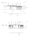
FIG. 1a is a longitudinal cross section of a transducer element according to the present invention taken along lines A-A inFigures 2a-2e ; -
FIG. 1b is a longitudinal cross section of a transducer element according to the present invention taken along lines B-B inFIGs. 2a-2e ; -
FIG. 2a is a cross section of a transducer element according to the present invention taken along line C-C inFIG. 1a ; -
FIG. 2b is a cross section of a transducer element according to the present invention taken along line D-D inFIG. 1a ; -
FIG. 2c is a cross section of a transducer element according to the present invention taken along line E-E inFIG. 1a ; -
FIG. 2d is a cross section of a transducer element according to the present invention taken along line F-F inFIG. 1a ; -
FIG. 2e is a cross section of a transducer element according to the present invention taken along line G-G inFIG. 1a ; -
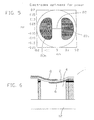
FIG. 3 shows the distribution of charge density across a piezoelectric layer of a transducer element resulting from the application of a constant pressure over the entire surface of the layer; -
FIG. 4 shows the results of optimization performed for the power response of a transducer according to the present invention; -
FIG. 5 shows a preferred electrode shape for maximizing the power response of a transducer according to the present invention; -
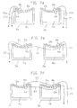
FIG. 6 is a longitudinal section of another embodiment of a transducer element according to the present invention capable of functioning as a transmitter; -
FIG. 7a-7f are schematic views of possible configurations of transmitters according to the present invention including parallel and anti-parallel electrical connections for controllably changing the mechanical impedance of the piezoelectric layer; -
FIG. 8 is a longitudinal section of a transmitter element according to the present invention including an anti-parallel electrical connection; -
FIG. 9 is a longitudinal section of another embodiment of a transmitter element according to the present invention; -
FIG. 10 is a block diagram depicting the intrabody and extracorporeal components of the biosensor system according to the present invention; -
FIG. 11 is a schematic depiction of components of the biosensor system according to one embodiment of the present invention; -
FIG. 12 is a longitudinal section of a shunt system including an acoustic transducer and pressure sensors according to another embodiment of the present invention; -
FIG. 13 is a schematic depiction of the transducer and pressure sensors ofFigure 12 isolated from the shunt; and -
FIG. 14 is a block diagram of the extracorporeal station components according to the present invention implemented within a helmet. - The present invention is of an intrabody bio-sensing system which can be used for both monitoring and alleviating physiological conditions within a patient's body. Specifically, the biosensor system of the present invention incorporates an active acoustic transducer communicating with sensors and optionally with a shunt implanted within the patient's body for monitoring and alleviating, for example, intra-cranial pressure of a patient suffering from hydrocephalus.
- The principles and operation of an implantable biosensor system according to the present invention may be better understood with reference to the drawings and accompanying descriptions.
- Before explaining at least one embodiment of the invention in detail, it is to be understood that the invention is not limited in its application to the details of construction and the arrangement of the components set forth in the following description or illustrated in the drawings. The invention is capable of other embodiments or of being practiced or carried out in various ways. Also, it is to be understood that the phraseology and terminology employed herein is for the purpose of description and should not be regarded as limiting. For purposes of better understanding the system according to the present invention, as illustrated in
Figures 10-14 of the drawings, reference is first made to the construction and operation of a transducer as described inU.S. Pat. application No. 09/000,553 . - Referring now to the drawings,
Figures 1a, 1b and2a-2e illustrate a preferred embodiment of a transducer element according to the present invention which is referred to herein astransducer element 1.Transducer element 1 serves for converting received acoustic signals into electrical power and for converting electrical power to transmitted acoustic signals. As shown in the figures, thetransducer element 1 includes at least onecell member 3 including acavity 4 etched into a substrate and covered by a substantially flexiblepiezoelectric layer 2. Attached topiezoelectric layer 2 are an upper electrode 8 and alower electrode 6, the electrodes for connection to an electronic circuit. - The substrate is preferably made of an
electrical conducting layer 11 disposed on an electrically insulatinglayer 12, such thatcavity 4 is etched substantially through the thickness of electrically conductinglayer 11. - Electrically conducting
layer 11 is preferably made of copper and insulatinglayer 12 is preferably made of a polymer such as polyimide. Conventional copper-plated polymer laminate such as KAPTON™ sheets may be used for the production oftransducer element 1. Commercially available laminates such as NOVACLAD™ may be used. Alternatively, the substrate may include a silicon layer, or any other suitable material. Alternatively,layer 11 is made of a non-conductive material such as PYRALIN™. - Preferably,
cavity 4 is etched into the substrate by using conventional printed-circuit photolithography methods. Alternatively,cavity 4 may be etched into the substrate by using VLSI/micro-machining technology or any other suitable technology. -
Piezoelectric layer 2 may be made of PVDF or a copolymer thereof. Alternatively,piezoelectric layer 2 is made of a substantially flexible piezoceramic. Preferably,piezoelectric layer 2 is a poled PVDF sheet having a thickness of about 9-28 µm. Preferably, the thickness and radius offlexible layer 2, as well as the pressure withincavity 4, are specifically selected so as to provide a predetermined resonant frequency. When using the embodiment ofFigures 1a and 1b , the radius oflayer 2 is defined by the radius ofcavity 4. - By using a substantially flexible
piezoelectric layer 2, the invention described inU.S. Pat. application No. 09/000,553 allows to provide a miniature transducer element whose resonant frequency is such that the acoustic wavelength is much larger than the extent of the transducer. This enables the transducer to be omnidirectional even at resonance, and further allows the use of relatively low frequency acoustic signals which do not suffer from significant attenuation in the surrounding medium. - Prior art designs of miniature transducers, however, rely on rigid piezoceramic usually operating in thickness mode. In such cases the resonant frequency relates to the size of the element and speed of sound in the piezoceramic, and is higher by several orders of magnitude.
- The invention described in
U.S. Pat. application No. 09/000,553 provides a transducer which is omnidirectional, i.e., insensitive to the direction of the impinging acoustic rays, thereby substantially simplifying the transducer's operation relative to other resonant devices. Such a transducer element is thus suitable for application in confined or hidden locations, where the orientation of the transducer element cannot be ascertained in advance. - According to a specific embodiment,
cavity 4 features a circular or hexagonal shape with radius of about 200 µm. Electrically conductinglayer 11 preferably has a thickness of about 15 µm.Cell member 3 is preferably etched completely through the thickness of electrically conductinglayer 11. Electrically insulatinglayer 12 preferably features a thickness of about 50 µm. The precise dimensions of the various elements of a transducer element according to the invention described inU.S. Pat. application No. 09/000,553 may be specifically tailored according to the requirements of the specific application. -
Cavity 4 preferably includes a gas such as air. The pressure of gas withincavity 4 may be specifically selected so as to predetermine the sensitivity and ruggedness of the transducer as well as the resonant frequency oflayer 2. - As shown in
Figure 2b , an insulatingchamber 18 is etched into the substrate, preferably through the thickness of conductinglayer 11, so as to insulate the transducer element from other portions of the substrate which may include other electrical components such as other transducer elements etched into the substrate. According to a specific embodiment, the width of insulatingchamber 18 is about 100 µm. As shown, insulatingchamber 18 is etched into the substrate so as to form awall 10 of a predeterminedthickness enclosing cavity 4, and a conductingline 17 integrally made withwall 10 for connecting the transducer element to another electronic component preferably etched into the same substrate, or to an external electronic circuit. - As shown in
Figures 1a and 1b , attached topiezoelectric layer 2 are upper electrode 8 andlower electrode 6. As shown inFigures 2c and 2e , upper electrode 8 andlower electrode 6 are preferably precisely shaped, so as to cover a predetermined area ofpiezoelectric layer 2.Electrodes 6 and 8 may be deposited on the upper and lower surfaces ofpiezoelectric membrane 2, respectively, by using various methods such as vacuum deposition, mask etching, painting, and the like. - As shown in
Figure 1a ,lower electrode 6 is preferably made as an integral part of a substantially thin electrically conductinglayer 14 disposed on electrically conductinglayer 11. Preferably, electrically conductinglayer 14 is made of a NickeLCopper alloy and is attached to electrically conductinglayer 11 by mechanism of asealing connection 16.Sealing connection 16 may be made of indium. According to a preferred configuration, sealingconnection 16 may feature a thickness of about 10 µ m, such that the overall height ofwall 10 ofcavity 4 is about 20-25 µm. - As shown in
Figure 2c , electrically conductinglayer 14 covers the various portions of conductinglayer 11, includingwall 10 and conductingline 17. The portion of conductinglayer 14covering conducting line 17 is for connection to an electronic component, as further detailed hereinunder. - According to a preferred embodiment,
electrodes 6 and 8 are specifically shaped to include the most energy-productive region ofpiezoelectric layer 2, so as to provide maximal response of the transducer while optimizing the electrode area, and therefore the cell capacitance, thereby maximizing a selected parameter such as voltage sensitivity, current sensitivity, or power sensitivity of the transducer element. - The vertical displacement of
piezoelectric layer 2, Ψ, resulting from a monochromatic excitation at angular frequency ω is modeled using the standard equation for thin plates:
wherein O is the Young's modulus representing the elasticity oflayer 2; h the half-thickness oflayer 2; v is the Poisson ratio forlayer 2; γ is the effective wavenumber in the layer given by: γ4 = 3ρ(1- v2)ω2/Qh 2,
wherein p is the density oflayer 2 and ω is the angular frequency of the applied pressure (wherein the applied pressure may include the acoustic pressure, the static pressure differential acrosslayer 2 and any other pressure the transducer comes across); Z is the mechanical impedance resulting from the coupling oflayer 2 to both external and internal media ofcavity 4, wherein the internal medium is preferably air and the external medium is preferably fluid; P is the acoustic pressure applied tolayer 2, andψ represents the average vertical displacement oflayer 2. - When
chamber 4 is circular, the solution (given for a single frequency component ω) representing the dynamic displacement of acircular layer 2 having a predetermined radius a, expressed in polar coordinates, is:


wherein Ψ(r,ϕ) is time-dependent and represents the displacement of a selected point located oncircular layer 2, the specific location of which is given by radius r and angle ϕ; J and I are the normal and modified Bessel functions of the first kind, respectively; PA, HA, are the air pressure withincavity 4 and the height ofchamber 4, respectively; and ρw is the density of the fluid external tocavity 4. - The first term of the impedance Z relates to the stiffness resulting from compression of air within
cavity 4, and the second term of Z relates to the mass added by the fluid boundary layer. An additional term of the impedance Z relating to the radiated acoustic energy is substantially negligible in this example. - The charge collected between
electrodes 6 and 8 per unit area is obtained by evaluating the strains inlayer 2 resulting from the displacements, and multiplying by the pertinent off-diagonal elements of the piezoelectric strain coefficient tensor, e 31, e 32, as follows:
wherein Q(r,ϕ,t) represents the charge density at a selected point located oncircular layer 2, the specific location of which is given by radius r and angle ϕ; x is the stretch direction ofpiezoelectric layer 2; y is the transverse direction (the direction perpendicular to the stretch direction) oflayer 2; e 31, e 32, are off-diagonal elements of the piezoelectric strain coefficient tensor representing the charge accumulated at a selected point onlayer 2 due to a given strain along the x and y directions, respectively, which coefficients being substantially dissimilar when using a PVDF layer. Ψ is the displacement oflayer 2, taken as the sum of the displacement for a given acoustic pressure P at frequency f, and the static displacement resulting from the pressure differential between the interior and exterior ofcavity 4, which displacements being extractable from the equations given above. - The total charge accumulated between
electrodes 6 and 8 is obtained by integrating Q(r, ϕ, t) over the entire area S of the electrode:
- The capacitance C of
piezoelectric layer 2 is given by:
piezoelectric layer 2; and 2h is the thickness ofpiezoelectric layer 2. - Accordingly, the voltage, current and power responses of
piezoelectric layer 2 are evaluated as follows:
- The DC components of Q are usually removed prior to the evaluation, since the DC currents are usually filtered out. The values of Q given above represent peak values of the AC components of Q, and should be modified accordingly, so as to obtain other required values such as RMS values.
- According to the above, the electrical output of the transducer expressed in terms of voltage, current and power responses depend on the AC components of Q, and on the shape S of the electrodes. Further, as can be seen from the above equations, the voltage response of the transducer may be substantially maximized by minimizing the area of the electrode. The current response, however, may be substantially maximized by maximizing the area of the electrode.
-
Figure 3 shows the distribution of charge density on a circularpiezoelectric layer 2 obtained as a result of pressure (acoustic and hydrostatic) applied uniformly over the entire area oflayer 2, wherein specific locations onlayer 2 are herein defined by using Cartesian coordinates including the stretch direction (x direction) and the transverse direction (y direction) oflayer 2. It can be seen that distinct locations onlayer 2 contribute differently to the charge density. The charge density vanishes at theexternal periphery 70 and at thecenter 72 oflayer 2 due to minimal deformation of these portions. The charge density is maximal at two cores 74a and 74b located symmetrically on each side ofcenter 72 due to maximal strains (in the stretch direction) of these portions. - A preferred strategy for optimizing the electrical responses of the transducer is to shape the electrode by selecting the areas contributing at least a selected threshold percentage of the maximal charge density,
wherein the threshold value is the parameter to be optimized. A threshold value of 0 % relates to an electrode covering the entire area oflayer 2. -
Figure 4 shows the results of an optimization performed for the power response of a transducer having alayer 2 of a predetermined area. As shown in the Figure, the threshold value which provides an optimal power response is about 30 % (graph b). Accordingly, an electrode which covers only the portions oflayer 2 contributing at least 30 % of the maximal charge density yields a maximal power response. The pertinent voltage response obtained by such an electrode is higher by a factor of 2 relative to an electrode completely covering layer 2 (graph a). The current response obtained by such electrode is slightly lower relative to an electrode completely covering layer 2 (graph c). Further as shown in the Figure, the deflection oflayer 2 is maximal when applying an acoustic signal at the resonant frequency of layer 2 (graph d). - A preferred electrode shape for maximizing the power response of the transducer is shown in
Figure 5 , wherein the electrode includes twoelectrode portions 80a and 80b substantially covering the maximal charge density portions oflayer 2, the electrode portions being interconnected by mechanism of a connectingmember 82 having a minimal area. Preferably,portions 80a and 80b cover the portions oflayer 2 which yield at least a selected threshold (e.g. 30 %) of the maximal charge density. - According to the present invention any other parameter may be optimized so as to determine the shape of
electrodes 6 and 8. According to further features of the invention described inU.S. Pat. application No. 09/000,553 , only one electrode (upper electrode 8 or lower electrode 6) may be shaped so as to provide maximal electrical response of the transducer, with the other electrode covering the entire area oflayer 2. Since the charge is collected only at the portions oflayer 2 received between upper electrode 8 andlower electrode 6, such configuration is operatively equivalent to a configuration including two shaped electrodes having identical shapes. - Referring now to
Figure 6 , according to anotherembodiment chamber 4 oftransducer element 1 may contain gas of substantially low pressure, thereby conferring a substantially concave shape topiezoelectric membrane 2 at equilibrium. Such configuration enables to further increase the electrical response of the transducer by increasing the total charge obtained for a given displacement oflayer 2. The total displacement in such an embodiment is given by: ψ = P 0Ψ DC + PΨ AC cosωt, wherein P 0 is the static pressure differential between the exterior and the interior ofcavity 4; ψ DC is the displacement resulting from P 0 ; P is the amplitude of the acoustic pressure; and ψ AC is the displacement resulting from P. - Accordingly, the strain along the x direction includes three terms as follows:

wherein the DC component is usually filtered out. - Thus, by decreasing the pressure of the medium (preferably air) within
cavity 4 relative to the pressure of the external medium (preferably fluid), the value of P 0 is increased, thereby increasing the value of the third term of the above equation. - Such embodiment makes it possible to increase the charge output of
layer 2 for a given displacement, thereby increasing the voltage, current and power responses of the transducer without having to increase the acoustic pressure P. Furthermore, such embodiment enables to further miniaturize the transducer since the same electrical response may be obtained for smaller acoustic deflections. Such embodiment is substantially more robust mechanically and therefore more durable than the embodiment shown inFigures 1a and 1b . Such further miniaturization of the transducer enables to use higher resonance frequencies relative to the embodiment shown inFigures 1a and 1b . - Preferably, a
transducer element 1 according to the invention described inU.S. Pat. application No. 09/000,553 is fabricated by using technologies which are in wide use in the microelectronics industry, so as to allow integration thereof with other conventional electronic components as further detailed hereinunder. When the transducer element includes a substrate such as Copper-polymer laminate or silicon, a variety of conventional electronic components may be fabricated onto the same substrate. - According to a preferred embodiment, a plurality of
cavities 4 may be etched into asingle substrate 12 and covered by a singlepiezoelectric layer 2, so as to provide a transducer element including a matrix of transducingcell members 3, thereby providing a larger energy collecting area of predetermined dimensions, while still retaining the advantage of miniature individualtransducing cell members 3. When using such configuration, the transducingcell members 3 may be electrically interconnected in parallel or serial connections, or combinations thereof, so as to tailor the voltage and current response of the transducer. Parallel connections are preferably used so as to increase the current output while serial connections are preferably used so as to increase the voltage output of the transducer. - Furthermore,
piezoelectric layer 2 may be completely depolarized and then repolarized at specific regions thereof, so as to provide a predetermined polarity to each of the transducingcell members 3. Such configuration enables to reduce the complexity of interconnections betweencell members 3. - A transducer element according to the invention described in
U.S. Pat. application No. 09/000,553 may be further used as a transmitter for transmitting information to a remote receiver by modulating the reflection of an external impinging acoustic wave arrived from a remote transmitter. - Referring to
Figure 6 , the transducer element shown may function as a transmitter element due to the asymmetric fluctuations ofpiezoelectric layer 2 with respect to positive and negative transient acoustic pressures obtained as a result of the pressure differential between the interior and exterior ofcavity 4. - A transmitter element according to the present invention preferably modulates the reflection of an external impinging acoustic wave by mechanism of a switching element connected thereto. The switching element encodes the information that is to be transmitted, such as the output of a sensor, thereby frequency modulating a reflected acoustic wave.
- Such configuration requires very little expenditure of energy from the transmitting module itself, since the acoustic wave that is received is externally generated, such that the only energy required for transmission is the energy of modulation.
- Specifically, the reflected acoustic signal is modulated by switching the switching element according to the frequency of a message electric signal arriving from another electronic component such as a sensor, so as to controllably change the mechanical impedance of
layer 2 according to the frequency of the message signal. - Preferably, a specific array of electrodes connected to a single cell member or alternatively to a plurality of cell members are used, so as to control the mechanical impedance of
layer 2. -
Figures 7a-7g illustrate possible configurations for controllably change the impedance oflayer 2 of a transmitter element. Referring toFigure 7a , a transmitter element according to the invention described inU.S. Pat. application No. 09/000,553 may include a first and second pairs of electrodes, the first pair including anupper electrode 40a and alower electrode 38a, and the second pair including anupper electrode 40b and alower electrode 38b.Electrodes lines 36a, 36b, 34a and 34b, respectively, the electrical circuit including a switching element (not shown), so as to alternately change the electrical connections of conductinglines 36a, 36b, 34a and 34b. - Preferably, the switching element switches between a parallel connection and an anti-parallel connection of the electrodes. A parallel connection decreases the mechanical impedance of
layer 2, wherein an anti-parallel connection increases the mechanical impedance oflayer 2. An anti-parallel connection may be obtained by interconnectingline 34a to 36b and line 34b to 36a. A parallel connection may be obtained by connectingline 34a to 34b and line 36a to 36b. Preferably, the switching frequency equals the frequency of a message signal arriving from an electrical component such as a sensor as further detailed hereinunder. - According to another embodiment shown in
Figure 7b ,upper electrode 40a is connected tolower electrode 38b by mechanism of a conductingline 28, andelectrodes lines layer 2. - In order to reduce the complexity of the electrical connections,
layer 2 may be depolarized and then repolarized at specific regions thereof. As shown inFigure 7c , the polarity of the portion oflayer 2 received betweenelectrodes layer 2 received betweenelectrodes electrodes line 28, and providing conductinglines electrodes - According to another embodiment, the transmitting element includes a plurality of transducing cell members, such that the mechanical impedance of
layer 2 controllably changed by appropriately interconnecting the cell members. - As shown in
Figure 7d , a firsttransducing cell member 3a including alayer 2a and acavity 4a, and a secondtransducing cell member 3b including alayer 2b and acavity 4b are preferably contained within the same substrate; and layers 2a and 2b are preferably integrally made. A first pair ofelectrodes including electrodes 6a and 8a is attached tolayer 2, and a second pair ofelectrode including electrodes layer 2b.Electrodes lines lines Figure 7a , thereby alternately decreasing and increasing the mechanical impedance oflayers -
Figure 7e illustrates another embodiment, wherein the first and second transducing cell members are interconnected by mechanism of an anti-parallel connection. As shown in the Figure, the polarity oflayer 2a is opposite to the polarity oflayer 2b, so as to reduce the complexity of the electrical connections betweencell members electrode 6b by mechanism of a conductingline 21, andelectrodes lines layers -
Figure 7f shows another embodiment, wherein the first and second transducing cell members are interconnected by mechanism of a parallel connection. As shown,electrodes 6a and 6b are interconnected by mechanism of conductingline 24,electrodes line 23, andelectrodes lines layers -
Figure 8 shows a possible configuration of two transducing cell members etched onto the same substrate and interconnected by mechanism of an anti-parallel connection. As shown in the Figure, the transducing cell members are covered by acommon piezoelectric layer 2, wherein the polarity of the portion oflayer 2 received betweenelectrodes 6a and 8a is opposite to the polarity of the portion oflayer 2 received betweenelectrodes Electrodes conducting line 9, andelectrodes 6a and 6b are provided with conductinglines 16 for connection to an electrical circuit. - Another embodiment of a transmitter element according to the present invention is shown in
Figure 9 . The transmitter element includes a transducing cell member having acavity 4 covered by a first and second piezoelectric layers, 50a and 50b, preferably having opposite polarities. Preferably, layers 50a and 50b are interconnected by mechanism of an insulatinglayer 52. Attached tolayer 50a are upper andlower electrodes layer 50b are upper andlower electrodes Electrodes lines - It will be appreciated that the above descriptions are intended only to serve as examples, and that many other embodiments are possible within the spirit and the scope of invention described in
U.S. Pat. application No. 09/000,553 . - As is detailed hereinunder, in preferred embodiments, the present invention exploits the advantages of the acoustic transducer described hereinabove and in
U.S. Pat. application No. 09/000,553 . - Thus, according to the present invention there is provided an implantable biosensor system, which is referred to hereinunder as
biosensor 100. -
Biosensor 100 is implantable within a patient's body for monitoring a physiological condition therein. In the course of its operation,biosensor 100 relays, on command, information in the form of acoustic signals pertaining to a parameter or parameters associated with the physiological condition as these are sensed by an implanted sensor or sensors. Furthermore,biosensor 100 according to the present invention is designed to be energized via an external acoustic interrogation signal. - As such,
biosensor 100 is wire and/or integral power source independent. In addition, since the human body is, in effect, a water body and further since acoustic radiation is readily propagatable, if so desired, within water bodies in all directions,biosensor 100 of the present invention provides advantages over the prior art in terms of effective implantable depth within the body and further in terms of interrogation signal positional effect. - As further detailed hereinunder, according to a preferred embodiment of the present
invention biosensor system 100 incorporates a shunt for alleviating a monitored physiological condition. - As shown in
Figure 10 , and according to one embodiment of the present invention, when implanted in a monitoring or treatment intra body site,biosensor 100 of the present invention is employed for sensing or monitoring one or more parameters of a physiological condition within the patient and for transmitting acoustic signals representative of this physiological condition or these parameters out of the patient's body. - According to this embodiment of the present invention,
biosensor 100 includes one ormore sensors 112 for sensing, monitoring or measuring one or more parameters of the physiological conditions of the patient. -
Biosensor 100 also includes anacoustic activatable transducer 114.Transducer 114 serves for receiving electrical signals fromsensors 112 and for converting such electrical signals into acoustic signals.Transducer 114 also serves for receiving externally generated acoustic interrogation signals and for converting such acoustic energy into electrical power which is used for energizingsensors 112 and forrendering biosensor 100 wire and integral power source independent. - As further shown in
Figure 10 ,transducer 114 includes a receivingassembly 117 and a transmittingassembly 118, preferably both are integrated into a single transceiver assembly. - According to a preferred embodiment of the present
invention receiving assembly 117 and transmittingassembly 118 are assembled oftransducer element 1, the construction of which is further detailed hereinabove with regards toFigures 1a, 1b and2a-2e . Alternatively, a plurality oftransducer elements 1 can also be utilized in various configurations (as shown inFigures 7b-f ,8 and 9 hereinabove) in the receivingassembly 117 and transmittingassembly 118 ofbiosensor 100 of the present invention The components oftransducer 114 can be formed fromseparate transducer element 1 units, although the integration of onetransducer element 1 into a transceiver is preferred, due to the high degree of miniaturization required in biosensing devices. - According to a preferred embodiment of the present invention signals received and/or transmitted by
biosensor 100 are processed by aprocessor 113. Electrical signals generated bysensors 112 are processed throughprocessor 113 and are forwarded in their processed or converted form totransducer 114. In addition, acoustic signals received bytransducer 114 and which are converted to electrical signals (and power) thereby, are preferably further processed byprocessor 113. - To this end,
processor 113, preferably includes aconditioner 116 and, when necessary, adigitizer 119 for processing the electrical signals received thereby fromsensors 112 and/ortransducer 114. - The acoustic interrogation signal is generated by an
extracorporeal station 130 which includes aninterrogator 115 and which is also illustrated inFigure 10 , the operation and construction of which is described in further detail below. -
Sensors 112 are operable for monitoring or detecting one or more physiological conditions within the patient's body, such as the pressure and/or the temperature of the cerebrospinal fluid in the cavities or ventricles of the patient's brain.Sensors 112 then generate sensor signals representative of these measured physiological parameters. The sensor signals are typically electrical analog signals but may also be digital, depending on the type of sensor employed. It will be appreciated that sensors having a built-in analog-to-digital converter are well known in the art. -
Sensors 112 are preferably conventional in construction and may include, for example, pressure sensors, temperature sensors, pH sensors, blood sugar sensors, blood oxygen sensors, or any other type of physiological sensing, monitoring or measuring devices responsive to, for example, motion, flow, velocity, acceleration, force, strain, acoustics, moisture, osmolarity, light, turbidity, radiation, electromagnetic fields, chemicals, ionic, or enzymatic quantities or changes, electrical and/or impedance. - Examples of these and other sensor devices useful in context of the present invention are described in detail in the AIP Handbook of Modem Sensors by Jacob Fraden, hereby incorporated by reference.
- In a preferred embodiment,
sensors 112 are pressure sensor transducers such as the PVDF sensors described inU.S. Pat. application 09/161,658 , which is incorporated herein by reference, or the MPX2000 series pressure sensors distributed by Motorola. - As mentioned above according to a preferred embodiment of the
present invention transducer 114 is electrically coupled tosensors 112 throughprocessor 113.Processor 113 conditions the sensor signals viaconditioner 116, converts the sensor signals to a digital form (when so required) viadigitizer 119, and provides the processed or converted signal totransducer 114. Upon a command,transducer 114 converts the processed electrical signals into corresponding acoustic signals which are concomitantly transmitted out of the patient's body, when subjected to an acoustic interrogation signal fromstation 130. - In more detail,
processor 113 is electrically connected tosensors 112 and both share a common miniature substrate such as is customary in the VLSI (Very Large Scale Integration) industry.Processor 113 directly receives sensors' 112 signals by, e.g., the shortest possible wiring. -
Processor 113 serves several functions. As already mentioned,processor 113 conditions viaconditioner 116 the signals received fromsensors 112. Such conditioning is necessary due to the miniature size and small capacitance ofsensors 112, and as such,conditioner 116 provides not only appropriate amplification and filtering, but also impedance reduction, so as to substantially reduce noise pickup and thereby improve the signal-to-noise ratio ofbiosensor 100. - In addition,
digitizer 119 is employed inprocessor 113 to convert the analog signals to digital signals and format the digitized signals as a binary data stream for transmission out of the patient bytransducer 114 acoustic signals, which are received and interpreted byextracorporeal station 130. -
Processor 113 is also operable for coding and formatting a unique device identification number for transmission with the sensors' signals for use in identifying aspecific transducer 114 and/orsensor 112. - Preferably,
processor 113 can be programmed to analyze the monitored signals before transmitting the signals out of the patient's body. To this end,processor 113 can be provided with a memory device and a programmable microprocessor. Many more tasks which are applicable tobiosensor system 100 of the present invention can be provided byprocessor 113, such as, for example, calculating a reading by correlating information derived from a plurality ofsensors 112. - For example, if
biosensor 100 is provided with a pressure sensor and a temperature sensor for measuring both the pressure and temperature of the cerebrospinal fluid in the patient's brain,processor 113 can then be programmed to adjust the pressure signal transmitted out of the patient's body to compensate for higher or lower temperature readings as sensed by the temperature sensor and vice versa, thereby providing more accurate readings. - It will, however, be appreciated by one ordinarily skilled in the art that sole or additional/supplementary processing can be effected by processors present in
extracorporeal station 130. - Preferably, transmitting
assembly 118 oftransducer 114 employs modulations or other methods in modifying the transmitted acoustic signal, such modulation methods are well known in the art and are described in detail in, for example,U.S. Pat. No. 5,619,997 which is incorporated herein by reference. -
Extracorporeal station 130 is located outside the patient's body and is designed for powering or energizingtransducer 114 ofbiosensor 100 which is implanted within the patient's body, and for receiving the sensors' acoustic signals. - As illustrated in
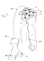
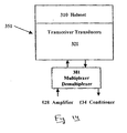
Figures 10-11 , according to one embodiment of the present invention and as further detailed in the following sections,transducers 321 ofstation 130 are mounted within ahelmet 310.Transducers 321 are coupled via wiring with asignal generator 126, apower amplifier 128, amodulator 132, ademodulator 133, asignal conditioner 134 and a recording and analyzingdevice 138. -
Signal generator 126 andpower amplifier 128 provide energy toextracorporeal transducer 321 for generating acoustic signals which propagate from the surface into the patient's body and energize intrabodyacoustic transducer 114 when impinging thereon.Signal generator 126 andpower amplifier 128 may be of any known type, including devices constructed in accordance with "Data Transmission from an Implantable Biotelemeter by Load-Shift Keying Using Circuit Configuration Modulator" by Zhengnian Tang, Brian Smith, John H. Schild, and P. Hunter Peckham, IEEE Transactions on Biomedical Engineering, vol. 42, No. 5, May, 1995, pp. 524-528, which is incorporated herein by reference. - As already mentioned,
transducers 321 are preferably of a type functionally similar totransducer element 1, the construction of which is further described hereinabove inFigures 1a, 1b ,2a-2e ,7b-f ,8 and 9 , each of which can serve as a transmitter, receiver or a transceiver, and are preferably constructed to comply with NCRP 113: Exposure criteria for medical diagnostic ultrasound 1992, parts I and II, provided thattransducers 321 when serve as a powering transmitter is capable of transmitting sufficient energy in the form of an acoustic signal for energizingbiosensor 100.Preferred transducers 321 include commercial piston type transducers. -
Transducers 321 are electrically connected topower amplifier 128 and acoustically communicable withtransducer 114.Transducers 321 transform and deliver the energy generated bygenerator 126 andpower amplifier 128 totransducer 114 via the body of the patient, which serves in this respect as a water body. -
Demodulator 133 is operatively coupled totransducers 321 and is provided for extracting digital data received thereby fromtransducer 114. An example of ademodulator 133 that can be used ininterrogator 115 ofextracorporeal station 130 is the MC1496 or MC1596 type demodulator distributed by Motorola. -
Signal conditioner 134 is connected to demodulator 133 for converting the demodulated data to a format suitable for recording or storing in external devices. An example of asignal conditioner 134 that can be used instation 130 of the present invention is the ADM202 type conditioner distributed by Analog Devices.Signal conditioner 134 may be connected with conventional recording and/or analyzing devices such as computers, printers, and displays for recording, presenting and/or further analyzing the signals transmitted bybiosensor 100. - Thus, and according to this embodiment of the present invention,
biosensor 100 described hereinabove is implanted in a patient for sensing, monitoring or detecting one or more parameters associated with a physiological condition of the patient. When it is desired to collect information from the body of the patient, acontrol console 124 commands interrogator 115 to trigger an energizing signal output fromsignal generator 126. The energizing signal is then modulated with other commands originating fromcontrol console 124 that governsprocessor 113 ofbiosensor 100 and multiplexer-demultiplexer 381. The modulated signal is amplified bypower amplifier 128 and sent totransducer 321 to energize and renderbiosensor 100 operative viatransducer 114 thereof. The energy thus provided through the body of the patient is also used to providetransducer 114 with energy to produce an acoustic signal related to the information thus collected bysensors 112. To this end,transducers 321 ofstation 130 are placed in intimate physical contact with a portion of the patient's body preferably in which biosensor 100 is implanted.Station 130 generates an acoustic interrogation signal viatransducers 321 for poweringbiosensor 100 and for retrieving viatransducers 114 sensors' 112 signals as an acoustic signal generated bytransducer 114.Interrogator 115 then demodulates sensors' 112 signals and delivers the signals to recording and analyzingdevice 138. - It will be appreciated that in cases where each of
sensors 112 provides information pertaining to a specific parameter, specific information from each ofsensors 112 can be accessed bystation 130 by providing a unique identifying code for each sensor with the acoustic interrogation signal. Such a code would be interpreted byprocessor 113 to command the retrieval of information from any specific sensor ofsensors 112. - Referring now to
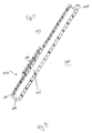
Figures 11-13 . According to another preferred embodiment of the present invention and as best illustrated inFigure 12 ,biosensor 100 further includes ashunt 202 for draining fluid from a portion of a patient's body, and amonitoring device 204 which is further detailed hereinbelow with respect toFigure 13 . According to a preferred embodiment,monitoring device 204 is embedded within the walls ofshunt 202 for non-invasively monitoring the operation ofshunt 202. - In more detail, shunt 202 according to this embodiment of the present invention is a cerebrospinal fluid shunt and is used for draining cerebrospinal fluid from a patient's brain, when so required.
Cerebrospinal fluid shunt 202 is preferably formed of medical grade synthetic resin material and presentsopposed ventricular 206 and distal 208 ends connected by afluid passageway 205 which includes avalve 105. Whenshunt 202 is implanted in a patient,ventricular end 206 is positioned in a ventricular cavity of the patient's brain anddistal end 208 is positioned in an organ or body cavity remote from the ventricular cavity so as to drain fluids from the patient's brain thereto. - As shown in
Figure 11 , an appropriate site to drain the cerebrospinal fluid out of the brain may be the abdomen cavity. A further appropriate site for drainage is immediately aftervalve 105, in order to make the shunt tubing as short as possible and largely simplify the implantation thereof in surgery. Such drainage is effected via atube 214 leading fromshunt 202 to the patients abdominal cavity. Another appropriate site for draining cerebrospinal fluid out of the patient's brain may be the patient's skull, close to the spine. In this case the drainage tube is much shorter, simplifying the implantation surgery and reducing the risk to the patient. In both case,valve 105 which forms a part of, and is operable by,biosensor 100 is preferably used for alleviating intracranial pressure viashunt 202. - As best illustrated in
Figure 12 ,monitoring device 204 is preferably formed or embedded within the sidewall ofshunt 202. - Referring to
Figure 13 ,monitoring device 204 preferably includes one ormore pressure sensors 212 and atransducer 214 which is electrically coupled withsensors 212. Likesensors 112,sensors 212 can include, for example, temperature sensors, pH sensors, blood sugar sensors, blood oxygen sensors, or any other type of physiological sensing, monitoring or measuring device responsive to, for example, motion, flow, velocity, acceleration, force, strain, acoustics, moisture, osmolarity, light, turbidity, radiation, electricity, electromagnetic fields, chemicals, ionic, or enzymatic quantities or changes. - According to a preferred embodiment of the present invention,
sensors 212 are provided for sensing the pressure of the cerebrospinal fluid inshunt passageway 205 and are preferably spaced a distance apart from one another for sensing pressure at different points withinpassageway 205.Sensors 212 may be placed anywhere withinshunt 202 and may include piezoelectric or piezo-resistive transducers, silicon capacitive pressure transducers, variable-resistance laminates of conductive ink, variable conductance elastomeric devices, strain gauges or similar types of pressure sensitive devices. -
Transducer 214 is also preferably formed or embedded within the sidewall of theshunt 202 and is coupled withsensors 212 for directly or indirectly (via a processor) receiving electrical pressure signals therefrom. - According to this embodiment of the
present invention biosensor 100 which includesmonitoring device 204 is implanted in a patient as illustrated generally inFigure 11 for draining or removing cerebrospinal fluid from the patient's brain for treating hydrocephalus.Monitoring device 204 which is preferably formed within the sidewalls ofshunt 202 senses or detects the pressure of the cerebrospinal fluid withinshunt 202 and delivers pressure signals totransducer 214. Preferably such monitoring is performed bysensors 212 periodically. Such periodic readings can be stored and processed within a processor for later access. - When it is desired to collect information from
sensors 212, station 130 (or atleast transducers 321 thereof) is placed adjacent a portion of the patient's body in which biosensor 100 is implanted. As described before,station 130 generates an interrogation signal delivered throughtransducers 321 for concomitantly poweringbiosensor 100 and retrieving data therefrom viatransducer 214 in a fashion similar to as described above with respect totransducer 114. Should the data collected indicate an abnormal intracranial pressure,valve 105 ofshunt 202 is opened to drain cerebrospinal fluid therethrough. To thisend station 130 can be commanded to provide power for the opening ofvalve 105. This operation can be controlled either manually or by a preprogrammed processor. - According to another preferred embodiment of the present invention and as shown in
Figures 11 and14 there is provided atransducing assembly 351 which forms a part ofstation 130. In one configuration, as best seen inFigure 11 ,assembly 351 is incorporated into ahelmet 310.Helmet 310 includes a plurality oftransducers 321, each may serve as a transmitter, receiver or transceiver, positioned at various locations so as to provide full transmittance/reception spatial coverage of the brain volume. - As shown in
Figure 11 , acable bundle 350 physically connects assembly 351 to multiplexer/demultiplexer 381, which is computer controlled. Multiplexer/demultiplexer 381 serves several functions, including (i) providing a transmittance signal totransducers 321 frompower amplifier 128; (ii) conveying sensors' 112 or 212 signals from the body to signalconditioner 134; (iii) providing a computer-controlled multiplexing fortransducers 321 when used as transmitters; (iv) providing multiplexing fortransducers 321 when used as receivers; and/or (v) providing decoupling between the high power transmission signals fromamplifier 128 and the low amplitude signals received from transmittingassembly 118 which is located within the body, intosignal conditioner 134. It will be appreciated that multiplexer/demultiplexer 381 both isolates and routes the transmitted and received signals. - According to a preferred embodiment of the present invention the operation of
assembly 351 included withinhelmet 310 is effected following pre calibration of the required location of the transducers over the helmet by, preferably, applying a method which is based on a positioning model. - Such a positioning model allows for an accurate placement of the extracorporeal transducers such that acoustic insonifying of the brain volume is provided at an approximately uniform level throughout.
- In addition, to achieve such uniformity a three dimensional acoustic propagation model of the skull and brain can also be applied.
- Employment of wide beam low frequency ultrasonic transducers may be advantageous in providing an economical coverage.
- In addition, focusing the acoustic beams of the extracorporeal transducers on the intrabody transducer is also advantageous because in such cases narrow beam transducers of low frequency ultrasound can be efficiently utilized.
- Thus, for appropriately positioning such extracorporeal transducers, either a positioning model or a converging (in-fire) spheroidal acoustic array model with scattering can be used to provide the positional information required. With each of the transducers configuration envisaged above, a first run calibration session is employed in which communication between the helmet (extracorporeal) transducers and the intrabody transducer is tested for maximal accuracy.
- The present invention is advantageous over the existing art because it employs acoustic signals which are more readily propagatable in water bodies, such as the human body, as compared to radio frequency signals.
- Although the invention has been described in conjunction with specific embodiments thereof, it is evident that many alternatives, modifications and variations will be apparent to those skilled in the art. Accordingly, it is intended to embrace all such alternatives, modifications and variations that fall within the scope of the appended claims.
Claims (12)
- An implantable biosensor system for monitoring a physiological condition in a patient, the biosensor system comprising:(a) at least one sensor for sensing at least one parameter of a physiological condition and for generating electrical sensor signals representative of the physiological condition; and(b) a processor(c) a first acoustic activatable transducer (1) being directly or indirectly coupled with said at least one sensor, said first acoustic activatable transducer (1) being for converting a received acoustic interrogation signal from outside the patient's body into an electrical power for energizing said processor, said first acoustic activatable transducer (1) further being for converting said electrical sensor signals of said at least one sensor into acoustic signals receivable out of the patient's body, such that information pertaining to said at least one parameter of the physiological condition can be relayed outside the patient's body upon generation of an acoustic interrogation signal, said first acoustic activatable transducer (1) having dimensions, and further having a resonant wavelength which is significantly larger than said dimensions,wherein said first acoustic activatable transducer includes:(i) a cell member (3) having a cavity (4);(ii) a substantially flexible piezoelectric layer (2) attached to said cell member (3), said piezoelectric layer (2) having an external surface and an internal surface, said piezoelectric layer featuring such dimensions so as to enable fluctuations thereof at its resonance frequency upon impinging of said acoustic interrogation signal; and(iii) a first electrode attached to said external surface and a second electrode attached to said internal surface.
- The biosensor system of claim 1, wherein the processor is coupled between said at least one sensor and said first acoustic activatable transducer, said processor being for converting said electrical sensor signals into converted electrical signals representative of the physiological condition, said processor being energized via said electrical power.
- The biosensor system of claim 1, wherein said piezoelectric layer is of a material selected from the group consisting of PVDF and piezoceramic.
- The biosensor system of claim 2, wherein said processor includes a conditioner and a digitizer for converting said electrical sensor signal to said converted electrical signal.
- The biosensor system of claim 2, wherein said converted electrical signal is a digital signal.
- The biosensor system of claim 2, wherein said processor, said first acoustic activatable transducer and said at least one sensor are co-integrated into a single biosensor device.
- The biosensor system of claim 1, further comprising:(d) an extracorporeal station positionable against the patient's body said extracorporeal station including an interrogation signal generator for generating said acoustic interrogation signal, said interrogation signal generator including at least one second transducer for transmitting said interrogation signal to said first acoustic activatable transducer and for receiving said receivable acoustic signals from said first acoustic activatable transducer.
- The biosensor system of claim 2, wherein said processor includes a memory device for storing said electrical sensor signals and an analyzer for analyzing said electrical sensor signals.
- The biosensor system of claim 8, wherein said processor includes a programmable microprocessor.
- The biosensor system of claim 1, further comprising a shunt operable by said electrical power generated by said first acoustic activatable transducer, said shunt having a tubular sidewall and opposed ends, wherein said at least one sensor and said first acoustic activatable transducer are embedded in said shunt sidewall.
- The biosensor system of claim 1, wherein said at least one sensor is selected from the group consisting of a pressure sensor, a temperature sensor, a pH sensor, a blood sugar sensor, a blood oxygen sensor, a motion sensor, a flow sensor, a velocity sensor, an acceleration sensor, a force sensor, a strain sensor, an acoustics sensor, a moisture sensor, an osmolarity sensor, a light sensor, a turbidity sensor, a radiation sensor, an electromagnetic field sensor, a chemical sensor, an ionic sensor, and an enzymatic sensor.
- The biosensor system of claim 1, wherein said first acoustic activatable transducer is capable of transmitting an identification code identifying said transducer.
Applications Claiming Priority (2)
| Application Number | Priority Date | Filing Date | Title |
|---|---|---|---|
| US303644 | 1981-09-18 | ||
| US09/303,644 US6432050B1 (en) | 1997-12-30 | 1999-05-03 | Implantable acoustic bio-sensing system and method |
Publications (2)
| Publication Number | Publication Date |
|---|---|
| EP1050264A1 EP1050264A1 (en) | 2000-11-08 |
| EP1050264B1 true EP1050264B1 (en) | 2008-03-12 |
Family
ID=23173059
Family Applications (1)
| Application Number | Title | Priority Date | Filing Date |
|---|---|---|---|
| EP00109256A Expired - Lifetime EP1050264B1 (en) | 1999-05-03 | 2000-04-28 | Implantable acoustic bio-sensing system and method |
Country Status (6)
| Country | Link |
|---|---|
| US (1) | US6432050B1 (en) |
| EP (1) | EP1050264B1 (en) |
| JP (2) | JP4693957B2 (en) |
| AT (1) | ATE388665T1 (en) |
| CA (1) | CA2306196A1 (en) |
| DE (1) | DE60038260T2 (en) |
Families Citing this family (125)
| Publication number | Priority date | Publication date | Assignee | Title |
|---|---|---|---|---|
| US20030036746A1 (en) | 2001-08-16 | 2003-02-20 | Avi Penner | Devices for intrabody delivery of molecules and systems and methods utilizing same |
| US7024248B2 (en) * | 2000-10-16 | 2006-04-04 | Remon Medical Technologies Ltd | Systems and methods for communicating with implantable devices |
| US7283874B2 (en) | 2000-10-16 | 2007-10-16 | Remon Medical Technologies Ltd. | Acoustically powered implantable stimulating device |
| US6764446B2 (en) | 2000-10-16 | 2004-07-20 | Remon Medical Technologies Ltd | Implantable pressure sensors and methods for making and using them |
| WO2002056761A2 (en) * | 2000-11-17 | 2002-07-25 | Noveon Ip Holdings Corp. | Acoustic-based remotely interrrogated diagnostic implant device and system |
| US7547283B2 (en) * | 2000-11-28 | 2009-06-16 | Physiosonics, Inc. | Methods for determining intracranial pressure non-invasively |
| US6694158B2 (en) * | 2001-04-11 | 2004-02-17 | Motorola, Inc. | System using a portable detection device for detection of an analyte through body tissue |
| DE10142019A1 (en) * | 2001-08-28 | 2003-03-20 | Philips Corp Intellectual Pty | Circuit arrangement for demodulating signals |
| US9694166B2 (en) | 2002-03-26 | 2017-07-04 | Medtronics Ps Medical, Inc. | Method of draining cerebrospinal fluid |
| US7061381B2 (en) * | 2002-04-05 | 2006-06-13 | Beezerbug Incorporated | Ultrasonic transmitter and receiver systems and products using the same |
| US8328420B2 (en) | 2003-04-22 | 2012-12-11 | Marcio Marc Abreu | Apparatus and method for measuring biologic parameters |
| US10123732B2 (en) | 2002-04-22 | 2018-11-13 | Geelux Holdings, Ltd. | Apparatus and method for measuring biologic parameters |
| US7187960B2 (en) * | 2002-04-22 | 2007-03-06 | Marcio Marc Abreu | Apparatus and method for measuring biologic parameters |
| US6941332B2 (en) | 2002-04-23 | 2005-09-06 | Medtronic, Inc. | Implantable medical device fast median filter |
| US7086042B2 (en) * | 2002-04-23 | 2006-08-01 | International Business Machines Corporation | Generating and utilizing robust XPath expressions |
| US6898461B2 (en) | 2002-04-23 | 2005-05-24 | Medtronic, Inc. | Implantable medical device stream processor |
| ATE479343T1 (en) * | 2002-10-01 | 2010-09-15 | Nellcor Puritan Bennett Inc | USE OF A HEADBAND FOR VOLTAGE DISPLAY AND SYSTEM OF OXYMETER AND HEADBAND |
| US7698909B2 (en) | 2002-10-01 | 2010-04-20 | Nellcor Puritan Bennett Llc | Headband with tension indicator |
| US7686762B1 (en) | 2002-10-03 | 2010-03-30 | Integrated Sensing Systems, Inc. | Wireless device and system for monitoring physiologic parameters |
| US7211048B1 (en) | 2002-10-07 | 2007-05-01 | Integrated Sensing Systems, Inc. | System for monitoring conduit obstruction |
| US20050256549A1 (en) * | 2002-10-09 | 2005-11-17 | Sirius Implantable Systems Ltd. | Micro-generator implant |
| US9740817B1 (en) | 2002-10-18 | 2017-08-22 | Dennis Sunga Fernandez | Apparatus for biological sensing and alerting of pharmaco-genomic mutation |
| US6685638B1 (en) * | 2002-12-23 | 2004-02-03 | Codman & Shurtleff, Inc. | Acoustic monitoring system |
| US8353857B2 (en) | 2003-06-23 | 2013-01-15 | Codman & Shurtleff, Inc. | Implantable medical device having pressure sensors for diagnosing the performance of an implanted medical device |
| US7047056B2 (en) | 2003-06-25 | 2006-05-16 | Nellcor Puritan Bennett Incorporated | Hat-based oximeter sensor |
| US8346482B2 (en) | 2003-08-22 | 2013-01-01 | Fernandez Dennis S | Integrated biosensor and simulation system for diagnosis and therapy |
| US7920906B2 (en) | 2005-03-10 | 2011-04-05 | Dexcom, Inc. | System and methods for processing analyte sensor data for sensor calibration |
| JP2007515195A (en) * | 2003-09-18 | 2007-06-14 | アドヴァンスド バイオ プロスセティック サーフェシーズ リミテッド | MEDICAL DEVICE HAVING MICRO ELECTRO-MACHINE SYSTEM FUNCTION AND METHOD FOR MANUFACTURING THE SAME |
| US20050065592A1 (en) * | 2003-09-23 | 2005-03-24 | Asher Holzer | System and method of aneurism monitoring and treatment |
| US8412297B2 (en) * | 2003-10-01 | 2013-04-02 | Covidien Lp | Forehead sensor placement |
| US9247900B2 (en) | 2004-07-13 | 2016-02-02 | Dexcom, Inc. | Analyte sensor |
| US7572228B2 (en) | 2004-01-13 | 2009-08-11 | Remon Medical Technologies Ltd | Devices for fixing a sensor in a lumen |
| US8165695B2 (en) | 2004-02-11 | 2012-04-24 | Ethicon, Inc. | System and method for selectively stimulating different body parts |
| US7647112B2 (en) * | 2004-02-11 | 2010-01-12 | Ethicon, Inc. | System and method for selectively stimulating different body parts |
| US8751003B2 (en) * | 2004-02-11 | 2014-06-10 | Ethicon, Inc. | Conductive mesh for neurostimulation |
| KR20060127975A (en) * | 2004-02-11 | 2006-12-13 | 에디컨인코포레이티드 | System and method for urodynamic evaluation utilizing micro-electronic mechanical system |
| US7979137B2 (en) * | 2004-02-11 | 2011-07-12 | Ethicon, Inc. | System and method for nerve stimulation |
| US7471986B2 (en) * | 2004-02-20 | 2008-12-30 | Cardiac Pacemakers, Inc. | System and method for transmitting energy to and establishing a communications network with one or more implanted devices |
| US10227063B2 (en) | 2004-02-26 | 2019-03-12 | Geelux Holdings, Ltd. | Method and apparatus for biological evaluation |
| WO2006010037A2 (en) | 2004-07-08 | 2006-01-26 | Deborah Schenberger | Strain monitoring system and apparatus |
| US7654956B2 (en) | 2004-07-13 | 2010-02-02 | Dexcom, Inc. | Transcutaneous analyte sensor |
| WO2006127694A2 (en) | 2004-07-13 | 2006-11-30 | Dexcom, Inc. | Analyte sensor |
| US20060064134A1 (en) * | 2004-09-17 | 2006-03-23 | Cardiac Pacemakers, Inc. | Systems and methods for deriving relative physiologic measurements |
| US8271093B2 (en) * | 2004-09-17 | 2012-09-18 | Cardiac Pacemakers, Inc. | Systems and methods for deriving relative physiologic measurements using a backend computing system |
| WO2006048664A2 (en) * | 2004-11-04 | 2006-05-11 | L & P 100 Limited | Medical devices |
| US7813808B1 (en) | 2004-11-24 | 2010-10-12 | Remon Medical Technologies Ltd | Implanted sensor system with optimized operational and sensing parameters |
| US20070232918A1 (en) * | 2004-12-06 | 2007-10-04 | William Taylor | Doppler helmet |
| US20060122513A1 (en) * | 2004-12-06 | 2006-06-08 | Taylor William G | Doppler helmet |
| US7585280B2 (en) * | 2004-12-29 | 2009-09-08 | Codman & Shurtleff, Inc. | System and method for measuring the pressure of a fluid system within a patient |
| US10390714B2 (en) | 2005-01-12 | 2019-08-27 | Remon Medical Technologies, Ltd. | Devices for fixing a sensor in a lumen |
| US20060200039A1 (en) * | 2005-02-16 | 2006-09-07 | Transoma Medical, Inc. | Impedance based sensor for monitoring leakage in AAA stent graft |
| US20080097277A1 (en) * | 2005-02-22 | 2008-04-24 | Saunders Richard L | Controllable Shunt |
| US8588930B2 (en) * | 2005-06-07 | 2013-11-19 | Ethicon, Inc. | Piezoelectric stimulation device |
| US8309057B2 (en) * | 2005-06-10 | 2012-11-13 | The Invention Science Fund I, Llc | Methods for elevating neurotrophic agents |
| US7742815B2 (en) | 2005-09-09 | 2010-06-22 | Cardiac Pacemakers, Inc. | Using implanted sensors for feedback control of implanted medical devices |
| US8649875B2 (en) | 2005-09-10 | 2014-02-11 | Artann Laboratories Inc. | Systems for remote generation of electrical signal in tissue based on time-reversal acoustics |
| ATE500517T1 (en) * | 2005-09-14 | 2011-03-15 | Us Gov Health & Human Serv | MRI CATHETER WITH MEANS FOR SUPPRESSING RESONANCE RF HEATING |
| KR101370985B1 (en) | 2005-10-24 | 2014-03-10 | 마시오 마크 아우렐리오 마틴스 애브리우 | Apparatus and method for measuring biologic parameters |
| US20070142727A1 (en) * | 2005-12-15 | 2007-06-21 | Cardiac Pacemakers, Inc. | System and method for analyzing cardiovascular pressure measurements made within a human body |
| US8060214B2 (en) | 2006-01-05 | 2011-11-15 | Cardiac Pacemakers, Inc. | Implantable medical device with inductive coil configurable for mechanical fixation |
| US8078278B2 (en) | 2006-01-10 | 2011-12-13 | Remon Medical Technologies Ltd. | Body attachable unit in wireless communication with implantable devices |
| US20070208390A1 (en) * | 2006-03-01 | 2007-09-06 | Von Arx Jeffrey A | Implantable wireless sound sensor |
| CN101454963A (en) * | 2006-03-17 | 2009-06-10 | 耐力节奏股份有限公司 | Energy generating systems for implanted medical devices |
| US7744542B2 (en) * | 2006-04-20 | 2010-06-29 | Cardiac Pacemakers, Inc. | Implanted air passage sensors |
| US7650185B2 (en) | 2006-04-25 | 2010-01-19 | Cardiac Pacemakers, Inc. | System and method for walking an implantable medical device from a sleep state |
| US7955268B2 (en) | 2006-07-21 | 2011-06-07 | Cardiac Pacemakers, Inc. | Multiple sensor deployment |
| US20080071248A1 (en) * | 2006-09-15 | 2008-03-20 | Cardiac Pacemakers, Inc. | Delivery stystem for an implantable physiologic sensor |
| ES2369203T3 (en) | 2006-09-15 | 2011-11-28 | Cardiac Pacemakers, Inc. | ANCHORAGE FOR AN IMPLANTABLE MEDICAL DEVICE. |
| US8676349B2 (en) | 2006-09-15 | 2014-03-18 | Cardiac Pacemakers, Inc. | Mechanism for releasably engaging an implantable medical device for implantation |
| US20080132962A1 (en) * | 2006-12-01 | 2008-06-05 | Diubaldi Anthony | System and method for affecting gatric functions |
| WO2008118908A1 (en) | 2007-03-26 | 2008-10-02 | Remon Medical Technologies, Ltd. | Biased acoustic switch for implantable medical device |
| US8204599B2 (en) | 2007-05-02 | 2012-06-19 | Cardiac Pacemakers, Inc. | System for anchoring an implantable sensor in a vessel |
| US7634318B2 (en) | 2007-06-14 | 2009-12-15 | Cardiac Pacemakers, Inc. | Multi-element acoustic recharging system |
| US8082041B1 (en) | 2007-06-15 | 2011-12-20 | Piezo Energy Technologies, LLC | Bio-implantable ultrasound energy capture and storage assembly including transmitter and receiver cooling |
| US8352026B2 (en) * | 2007-10-03 | 2013-01-08 | Ethicon, Inc. | Implantable pulse generators and methods for selective nerve stimulation |
| US8915866B2 (en) * | 2008-01-18 | 2014-12-23 | Warsaw Orthopedic, Inc. | Implantable sensor and associated methods |
| WO2009096851A1 (en) * | 2008-01-28 | 2009-08-06 | Milux Holding Sa | A drainage device comprising a filter cleaning device |
| JP5211177B2 (en) | 2008-02-11 | 2013-06-12 | カーディアック ペースメイカーズ, インコーポレイテッド | Hemodynamic monitoring method for rhythm discrimination in the heart |
| WO2009102640A1 (en) | 2008-02-12 | 2009-08-20 | Cardiac Pacemakers, Inc. | Systems and methods for controlling wireless signal transfers between ultrasound-enabled medical devices |
| US20090204019A1 (en) * | 2008-02-13 | 2009-08-13 | Alec Ginggen | Combined Pressure and Flow Sensor Integrated in a Shunt System |
| CA2715628A1 (en) | 2008-02-21 | 2009-08-27 | Dexcom, Inc. | Systems and methods for processing, transmitting and displaying sensor data |
| US8798761B2 (en) | 2008-06-27 | 2014-08-05 | Cardiac Pacemakers, Inc. | Systems and methods of monitoring the acoustic coupling of medical devices |
| EP2339955B1 (en) * | 2008-07-14 | 2012-09-05 | École Polytechnique Fédérale de Lausanne (EPFL) | Viscosimetric biosensor for monitoring analyte levels |
| EP2296536A1 (en) | 2008-07-15 | 2011-03-23 | Cardiac Pacemakers, Inc. | Implant assist apparatus for acoustically enabled implantable medical device |
| CN102159129A (en) * | 2008-07-18 | 2011-08-17 | 耐卡拉特两合公司 | System for regulating intracranial pressure |
| US20100152608A1 (en) * | 2008-09-12 | 2010-06-17 | Hatlestad John D | Chronically implanted abdominal pressure sensor for continuous ambulatory assessment of renal functions |
| US8257274B2 (en) | 2008-09-25 | 2012-09-04 | Nellcor Puritan Bennett Llc | Medical sensor and technique for using the same |
| US8364220B2 (en) | 2008-09-25 | 2013-01-29 | Covidien Lp | Medical sensor and technique for using the same |
| JP5465252B2 (en) | 2008-10-10 | 2014-04-09 | カーディアック ペースメイカーズ, インコーポレイテッド | System and method for determining cardiac output using pulmonary artery pressure measurements |
| US8593107B2 (en) | 2008-10-27 | 2013-11-26 | Cardiac Pacemakers, Inc. | Methods and systems for recharging an implanted device by delivering a section of a charging device adjacent the implanted device within a body |
| US8632470B2 (en) | 2008-11-19 | 2014-01-21 | Cardiac Pacemakers, Inc. | Assessment of pulmonary vascular resistance via pulmonary artery pressure |
| US9631610B2 (en) | 2008-12-04 | 2017-04-25 | Deep Science, Llc | System for powering devices from intraluminal pressure changes |
| US20100140958A1 (en) * | 2008-12-04 | 2010-06-10 | Searete Llc, A Limited Liability Corporation Of The State Of Delaware | Method for powering devices from intraluminal pressure changes |
| US9526418B2 (en) | 2008-12-04 | 2016-12-27 | Deep Science, Llc | Device for storage of intraluminally generated power |
| US9567983B2 (en) * | 2008-12-04 | 2017-02-14 | Deep Science, Llc | Method for generation of power from intraluminal pressure changes |
| US9353733B2 (en) | 2008-12-04 | 2016-05-31 | Deep Science, Llc | Device and system for generation of power from intraluminal pressure changes |
| US9759202B2 (en) * | 2008-12-04 | 2017-09-12 | Deep Science, Llc | Method for generation of power from intraluminal pressure changes |
| US8126736B2 (en) | 2009-01-23 | 2012-02-28 | Warsaw Orthopedic, Inc. | Methods and systems for diagnosing, treating, or tracking spinal disorders |
| US8685093B2 (en) | 2009-01-23 | 2014-04-01 | Warsaw Orthopedic, Inc. | Methods and systems for diagnosing, treating, or tracking spinal disorders |
| US8694129B2 (en) | 2009-02-13 | 2014-04-08 | Cardiac Pacemakers, Inc. | Deployable sensor platform on the lead system of an implantable device |
| DE102009009880A1 (en) * | 2009-02-20 | 2010-10-14 | Fraunhofer-Gesellschaft zur Förderung der angewandten Forschung e.V. | Valve for use in a conduit for carrying a fluid |
| US8088091B2 (en) * | 2009-03-09 | 2012-01-03 | New Jersey Institute Of Technology | No clog shunt using a compact fluid drag path |
| US8515515B2 (en) | 2009-03-25 | 2013-08-20 | Covidien Lp | Medical sensor with compressible light barrier and technique for using the same |
| US8781548B2 (en) | 2009-03-31 | 2014-07-15 | Covidien Lp | Medical sensor with flexible components and technique for using the same |
| EP3970610A3 (en) | 2009-07-02 | 2022-05-18 | Dexcom, Inc. | Analyte sensors and methods of manufacturing same |
| US11169010B2 (en) * | 2009-07-27 | 2021-11-09 | Integra Lifesciences Switzerland Sàrl | Method for the calibration of an implantable sensor |
| US8376937B2 (en) * | 2010-01-28 | 2013-02-19 | Warsaw Orhtopedic, Inc. | Tissue monitoring surgical retractor system |
| US9452289B2 (en) | 2011-03-18 | 2016-09-27 | Pixium Vision Sa | Method for identification of retinal cell types intrinsic properties |
| DE102011055284A1 (en) * | 2011-11-11 | 2013-05-16 | Aesculap Ag | Implantable pressure measuring device |
| US8974366B1 (en) | 2012-01-10 | 2015-03-10 | Piezo Energy Technologies, LLC | High power ultrasound wireless transcutaneous energy transfer (US-TET) source |
| US20140171751A1 (en) * | 2012-12-19 | 2014-06-19 | Robert L. Sankman | Electronic bio monitoring patch |
| JP6126388B2 (en) * | 2013-01-25 | 2017-05-10 | 積水化学工業株式会社 | Biological signal sensor and biological signal sensor system using the same |
| US9333368B2 (en) * | 2013-02-01 | 2016-05-10 | Old Dominion University Research Foundation | Treatment of biological tissues using subnanosecond electric pulses |
| US9990861B2 (en) | 2013-05-28 | 2018-06-05 | Pixium Vision | Smart prosthesis for facilitating artificial vision using scene abstraction |
| WO2015054681A1 (en) | 2013-10-11 | 2015-04-16 | Marcio Marc Abreu | Method and apparatus for biological evaluation |
| AU2015204638A1 (en) | 2014-01-10 | 2016-07-21 | Marcio Marc Abreu | Device for measuring the infrared output of the Abreu brain thermal tunnel |
| CA2936235A1 (en) | 2014-01-10 | 2015-07-16 | Marcio Marc Abreu | Devices to monitor and provide treatment at an abreu brain tunnel |
| US10238847B2 (en) | 2014-01-22 | 2019-03-26 | Geelux Holdings, Ltd. | Devices and methods for transdermal drug delivery |
| WO2016145215A1 (en) | 2015-03-10 | 2016-09-15 | Marcio Marc Abreu | Devices, apparatuses, systems, and methods for measuring temperature of an abtt terminus |
| US10226193B2 (en) | 2015-03-31 | 2019-03-12 | Medtronic Ps Medical, Inc. | Wireless pressure measurement and monitoring for shunts |
| US9757574B2 (en) | 2015-05-11 | 2017-09-12 | Rainbow Medical Ltd. | Dual chamber transvenous pacemaker |
| US20170340223A1 (en) * | 2016-05-31 | 2017-11-30 | ChuangHui Medical Technology Inc. | Implantable Automatic Wireless Intracranial Pressure Monitoring System and Method |
| BR102017023879A2 (en) * | 2017-11-06 | 2019-06-04 | Braincare Desenvolvimento E Inovação Tecnológica S.A. | SYSTEM AND METHOD OF MONITORING AND INTRACRANIAL PRESSURE MANAGEMENT WITHOUT INVASIVE WIRE |
| US11043745B2 (en) | 2019-02-11 | 2021-06-22 | Old Dominion University Research Foundation | Resistively loaded dielectric biconical antennas for non-invasive treatment |
| US20220378291A1 (en) * | 2021-06-01 | 2022-12-01 | Twenty Twenty Therapeutics Llc | Ultrasound Intraocular Pressure Sensor in Sclera or in Cornea |
Family Cites Families (28)
| Publication number | Priority date | Publication date | Assignee | Title |
|---|---|---|---|---|
| US3943915A (en) | 1974-11-29 | 1976-03-16 | Motorola, Inc. | Intracranial pressure sensing device |
| US4593703A (en) | 1976-06-21 | 1986-06-10 | Cosman Eric R | Telemetric differential pressure sensor with the improvement of a conductive shorted loop tuning element and a resonant circuit |
| US4198987A (en) * | 1978-01-09 | 1980-04-22 | Cain Clarence P | Measuring system including elements implantable beneath the skin |
| JPS57177735A (en) * | 1981-04-27 | 1982-11-01 | Toyoda Chuo Kenkyusho Kk | Telemeter type brain nanometer |
| US4494950A (en) * | 1982-01-19 | 1985-01-22 | The Johns Hopkins University | Plural module medication delivery system |
| FR2531298B1 (en) * | 1982-07-30 | 1986-06-27 | Thomson Csf | HALF-WAVE TYPE TRANSDUCER WITH PIEZOELECTRIC POLYMER ELEMENT |
| JPS59164035A (en) * | 1983-03-09 | 1984-09-17 | 三菱電機株式会社 | Internal pressure measuring apparatus of living body tissue |
| US4677985A (en) | 1985-08-12 | 1987-07-07 | Bro William J | Apparatus and method for determining intracranial pressure and local cerebral blood flow |
| JPS62102734A (en) * | 1985-10-31 | 1987-05-13 | 東洋通信機株式会社 | Card for receiving sensor for measuring temperature in living body |
| JPH0523323A (en) * | 1991-07-22 | 1993-02-02 | Nippon Zeon Co Ltd | Intracorporeal information monitoring apparatus |
| IL108470A (en) | 1994-01-28 | 1998-12-06 | Mizur Technology Ltd | Passive sensor system using ultrasonic energy |
| SE9401402D0 (en) * | 1994-04-25 | 1994-04-25 | Siemens Elema Ab | Medical implant |
| JP2720834B2 (en) * | 1995-05-30 | 1998-03-04 | 日本電気株式会社 | Acoustic communication device |
| US5743267A (en) * | 1995-10-19 | 1998-04-28 | Telecom Medical, Inc. | System and method to monitor the heart of a patient |
| JPH09147284A (en) * | 1995-11-07 | 1997-06-06 | Siemens Ag | Radio inquiry device operated by surface acoustic wave |
| US5704352A (en) * | 1995-11-22 | 1998-01-06 | Tremblay; Gerald F. | Implantable passive bio-sensor |
| IL125758A (en) * | 1996-02-15 | 2003-07-06 | Biosense Inc | Medical probes with field transducers |
| JP3626269B2 (en) * | 1996-02-29 | 2005-03-02 | 横浜ゴム株式会社 | Transponder fitted tire |
| US5833603A (en) * | 1996-03-13 | 1998-11-10 | Lipomatrix, Inc. | Implantable biosensing transponder |
| EP0827105A3 (en) * | 1996-08-29 | 2000-10-25 | Siemens Aktiengesellschaft | Identification or sensing device operating with acoustic surface waves |
| US5749909A (en) * | 1996-11-07 | 1998-05-12 | Sulzer Intermedics Inc. | Transcutaneous energy coupling using piezoelectric device |
| US6999685B1 (en) * | 1997-01-31 | 2006-02-14 | Seiko Epson Corporation | Polarized light communication device, transmitter, laser, polarized light communication device for physiological use, reflected light detector and pulse wave detecting device |
| US6015387A (en) * | 1997-03-20 | 2000-01-18 | Medivas, Llc | Implantation devices for monitoring and regulating blood flow |
| WO1998052142A1 (en) * | 1997-05-14 | 1998-11-19 | Btg International Limited | Enhanced identification system |
| EP0995129A4 (en) * | 1997-07-16 | 2000-10-18 | Stevens Inst Technology | Method and apparatus for acoustic detection of mines and other buried man-made objects |
| US5807258A (en) * | 1997-10-14 | 1998-09-15 | Cimochowski; George E. | Ultrasonic sensors for monitoring the condition of a vascular graft |
| US5891180A (en) * | 1998-04-29 | 1999-04-06 | Medtronic Inc. | Interrogation of an implantable medical device using audible sound communication |
| US6170488B1 (en) * | 1999-03-24 | 2001-01-09 | The B. F. Goodrich Company | Acoustic-based remotely interrogated diagnostic implant device and system |
-
1999
- 1999-05-03 US US09/303,644 patent/US6432050B1/en not_active Expired - Lifetime
-
2000
- 2000-04-19 CA CA002306196A patent/CA2306196A1/en not_active Abandoned
- 2000-04-28 AT AT00109256T patent/ATE388665T1/en not_active IP Right Cessation
- 2000-04-28 DE DE60038260T patent/DE60038260T2/en not_active Expired - Lifetime
- 2000-04-28 EP EP00109256A patent/EP1050264B1/en not_active Expired - Lifetime
- 2000-05-08 JP JP2000135205A patent/JP4693957B2/en not_active Expired - Fee Related
-
2011
- 2011-01-28 JP JP2011017259A patent/JP5127939B2/en not_active Expired - Fee Related
Also Published As
| Publication number | Publication date |
|---|---|
| US6432050B1 (en) | 2002-08-13 |
| JP2000350708A (en) | 2000-12-19 |
| CA2306196A1 (en) | 2000-11-03 |
| ATE388665T1 (en) | 2008-03-15 |
| EP1050264A1 (en) | 2000-11-08 |
| JP4693957B2 (en) | 2011-06-01 |
| JP5127939B2 (en) | 2013-01-23 |
| DE60038260T2 (en) | 2009-03-19 |
| JP2011101821A (en) | 2011-05-26 |
| DE60038260D1 (en) | 2008-04-24 |
Similar Documents
| Publication | Publication Date | Title |
|---|---|---|
| EP1050264B1 (en) | Implantable acoustic bio-sensing system and method | |
| US6198965B1 (en) | Acoustic telemetry system and method for monitoring a rejection reaction of a transplanted organ | |
| US5704352A (en) | Implantable passive bio-sensor | |
| US6239724B1 (en) | System and method for telemetrically providing intrabody spatial position | |
| US6431175B1 (en) | System and method for directing and monitoring radiation | |
| US6330885B1 (en) | Remotely interrogated implant device with sensor for detecting accretion of biological matter | |
| US6277078B1 (en) | System and method for monitoring a parameter associated with the performance of a heart | |
| US6237398B1 (en) | System and method for monitoring pressure, flow and constriction parameters of plumbing and blood vessels | |
| US8343068B2 (en) | Sensor unit and procedure for monitoring intracranial physiological properties | |
| US9364362B2 (en) | Implantable device system | |
| US8070695B2 (en) | Strain monitoring system and apparatus | |
| US6546268B1 (en) | Glucose sensor | |
| US20090048518A1 (en) | Doppler motion sensor apparatus and method of using same | |
| US20130247644A1 (en) | Implantable pressure sensor | |
| US20110178578A1 (en) | Piezoelectric transducer | |
| US20080269573A1 (en) | Procedure and system for monitoring a physiological parameter within an internal organ of a living body | |
| US20010026111A1 (en) | Acoustic biosensor for monitoring physiological conditions in a body implantation site | |
| WO2009138882A2 (en) | Doppler motion sensor apparatus and method of using same | |
| WO2010027963A1 (en) | Apparatus, system, and method for ultrasound powered neurotelemetry | |
| US20220054808A1 (en) | Device For Detecting A Malfunctioning Of A Ventriculoperitoneal Shunt For Cerebrospinal Fluid | |
| US20160183842A1 (en) | Minimally-invasive procedures for monitoring physiological parameters within internal organs and anchors therefor | |
| WO2002056761A2 (en) | Acoustic-based remotely interrrogated diagnostic implant device and system |
Legal Events
| Date | Code | Title | Description |
|---|---|---|---|
| PUAI | Public reference made under article 153(3) epc to a published international application that has entered the european phase |
Free format text: ORIGINAL CODE: 0009012 |
|
| AK | Designated contracting states |
Kind code of ref document: A1 Designated state(s): AT BE CH CY DE DK ES FI FR GB GR IE IT LI LU MC NL PT SE |
|
| AX | Request for extension of the european patent |
Free format text: AL;LT;LV;MK;RO;SI |
|
| 17P | Request for examination filed |
Effective date: 20010104 |
|
| AKX | Designation fees paid |
Free format text: AT BE CH CY DE DK ES FI FR GB GR IE IT LI LU MC NL PT SE |
|
| 17Q | First examination report despatched |
Effective date: 20031107 |
|
| 17Q | First examination report despatched |
Effective date: 20031107 |
|
| GRAP | Despatch of communication of intention to grant a patent |
Free format text: ORIGINAL CODE: EPIDOSNIGR1 |
|
| GRAS | Grant fee paid |
Free format text: ORIGINAL CODE: EPIDOSNIGR3 |
|
| GRAA | (expected) grant |
Free format text: ORIGINAL CODE: 0009210 |
|
| AK | Designated contracting states |
Kind code of ref document: B1 Designated state(s): AT BE CH CY DE DK ES FI FR GB GR IE IT LI LU MC NL PT SE |
|
| REG | Reference to a national code |
Ref country code: GB Ref legal event code: FG4D |
|
| REG | Reference to a national code |
Ref country code: CH Ref legal event code: EP |
|
| REG | Reference to a national code |
Ref country code: IE Ref legal event code: FG4D |
|
| REF | Corresponds to: |
Ref document number: 60038260 Country of ref document: DE Date of ref document: 20080424 Kind code of ref document: P |
|
| PG25 | Lapsed in a contracting state [announced via postgrant information from national office to epo] |
Ref country code: FI Free format text: LAPSE BECAUSE OF FAILURE TO SUBMIT A TRANSLATION OF THE DESCRIPTION OR TO PAY THE FEE WITHIN THE PRESCRIBED TIME-LIMIT Effective date: 20080312 |
|
| PG25 | Lapsed in a contracting state [announced via postgrant information from national office to epo] |
Ref country code: AT Free format text: LAPSE BECAUSE OF FAILURE TO SUBMIT A TRANSLATION OF THE DESCRIPTION OR TO PAY THE FEE WITHIN THE PRESCRIBED TIME-LIMIT Effective date: 20080312 |
|
| NLV1 | Nl: lapsed or annulled due to failure to fulfill the requirements of art. 29p and 29m of the patents act | ||
| PG25 | Lapsed in a contracting state [announced via postgrant information from national office to epo] |
Ref country code: BE Free format text: LAPSE BECAUSE OF FAILURE TO SUBMIT A TRANSLATION OF THE DESCRIPTION OR TO PAY THE FEE WITHIN THE PRESCRIBED TIME-LIMIT Effective date: 20080312 |
|
| PG25 | Lapsed in a contracting state [announced via postgrant information from national office to epo] |
Ref country code: PT Free format text: LAPSE BECAUSE OF FAILURE TO SUBMIT A TRANSLATION OF THE DESCRIPTION OR TO PAY THE FEE WITHIN THE PRESCRIBED TIME-LIMIT Effective date: 20080814 Ref country code: ES Free format text: LAPSE BECAUSE OF FAILURE TO SUBMIT A TRANSLATION OF THE DESCRIPTION OR TO PAY THE FEE WITHIN THE PRESCRIBED TIME-LIMIT Effective date: 20080623 Ref country code: SE Free format text: LAPSE BECAUSE OF FAILURE TO SUBMIT A TRANSLATION OF THE DESCRIPTION OR TO PAY THE FEE WITHIN THE PRESCRIBED TIME-LIMIT Effective date: 20080612 |
|
| PG25 | Lapsed in a contracting state [announced via postgrant information from national office to epo] |
Ref country code: MC Free format text: LAPSE BECAUSE OF NON-PAYMENT OF DUE FEES Effective date: 20080430 Ref country code: NL Free format text: LAPSE BECAUSE OF FAILURE TO SUBMIT A TRANSLATION OF THE DESCRIPTION OR TO PAY THE FEE WITHIN THE PRESCRIBED TIME-LIMIT Effective date: 20080312 |
|
| REG | Reference to a national code |
Ref country code: CH Ref legal event code: PL |
|
| EN | Fr: translation not filed | ||
| PLBE | No opposition filed within time limit |
Free format text: ORIGINAL CODE: 0009261 |
|
| STAA | Information on the status of an ep patent application or granted ep patent |
Free format text: STATUS: NO OPPOSITION FILED WITHIN TIME LIMIT |
|
| PG25 | Lapsed in a contracting state [announced via postgrant information from national office to epo] |
Ref country code: LI Free format text: LAPSE BECAUSE OF NON-PAYMENT OF DUE FEES Effective date: 20080430 Ref country code: DK Free format text: LAPSE BECAUSE OF FAILURE TO SUBMIT A TRANSLATION OF THE DESCRIPTION OR TO PAY THE FEE WITHIN THE PRESCRIBED TIME-LIMIT Effective date: 20080312 Ref country code: CH Free format text: LAPSE BECAUSE OF NON-PAYMENT OF DUE FEES Effective date: 20080430 |
|
| 26N | No opposition filed |
Effective date: 20081215 |
|
| PG25 | Lapsed in a contracting state [announced via postgrant information from national office to epo] |
Ref country code: IE Free format text: LAPSE BECAUSE OF NON-PAYMENT OF DUE FEES Effective date: 20080428 Ref country code: FR Free format text: LAPSE BECAUSE OF FAILURE TO SUBMIT A TRANSLATION OF THE DESCRIPTION OR TO PAY THE FEE WITHIN THE PRESCRIBED TIME-LIMIT Effective date: 20090102 |
|
| PG25 | Lapsed in a contracting state [announced via postgrant information from national office to epo] |
Ref country code: CY Free format text: LAPSE BECAUSE OF FAILURE TO SUBMIT A TRANSLATION OF THE DESCRIPTION OR TO PAY THE FEE WITHIN THE PRESCRIBED TIME-LIMIT Effective date: 20080312 |
|
| PG25 | Lapsed in a contracting state [announced via postgrant information from national office to epo] |
Ref country code: LU Free format text: LAPSE BECAUSE OF NON-PAYMENT OF DUE FEES Effective date: 20080428 |
|
| PGFP | Annual fee paid to national office [announced via postgrant information from national office to epo] |
Ref country code: GB Payment date: 20100325 Year of fee payment: 11 |
|
| PGFP | Annual fee paid to national office [announced via postgrant information from national office to epo] |
Ref country code: IT Payment date: 20100421 Year of fee payment: 11 Ref country code: DE Payment date: 20100430 Year of fee payment: 11 |
|
| PG25 | Lapsed in a contracting state [announced via postgrant information from national office to epo] |
Ref country code: GR Free format text: LAPSE BECAUSE OF FAILURE TO SUBMIT A TRANSLATION OF THE DESCRIPTION OR TO PAY THE FEE WITHIN THE PRESCRIBED TIME-LIMIT Effective date: 20080613 |
|
| REG | Reference to a national code |
Ref country code: DE Ref legal event code: R119 Ref document number: 60038260 Country of ref document: DE |
|
| REG | Reference to a national code |
Ref country code: DE Ref legal event code: R119 Ref document number: 60038260 Country of ref document: DE |
|
| GBPC | Gb: european patent ceased through non-payment of renewal fee |
Effective date: 20110428 |
|
| PG25 | Lapsed in a contracting state [announced via postgrant information from national office to epo] |
Ref country code: GB Free format text: LAPSE BECAUSE OF NON-PAYMENT OF DUE FEES Effective date: 20110428 Ref country code: IT Free format text: LAPSE BECAUSE OF NON-PAYMENT OF DUE FEES Effective date: 20110428 |
|
| PG25 | Lapsed in a contracting state [announced via postgrant information from national office to epo] |
Ref country code: DE Free format text: LAPSE BECAUSE OF NON-PAYMENT OF DUE FEES Effective date: 20111031 |