EP1052228A1 - Process for cleaning waste water and plant therefore - Google Patents
Process for cleaning waste water and plant therefore Download PDFInfo
- Publication number
- EP1052228A1 EP1052228A1 EP99109592A EP99109592A EP1052228A1 EP 1052228 A1 EP1052228 A1 EP 1052228A1 EP 99109592 A EP99109592 A EP 99109592A EP 99109592 A EP99109592 A EP 99109592A EP 1052228 A1 EP1052228 A1 EP 1052228A1
- Authority
- EP
- European Patent Office
- Prior art keywords
- phase
- biological reactor
- compressed air
- reactor
- ventilation
- Prior art date
- Legal status (The legal status is an assumption and is not a legal conclusion. Google has not performed a legal analysis and makes no representation as to the accuracy of the status listed.)
- Withdrawn
Links
Images
Classifications
-
- C—CHEMISTRY; METALLURGY
- C02—TREATMENT OF WATER, WASTE WATER, SEWAGE, OR SLUDGE
- C02F—TREATMENT OF WATER, WASTE WATER, SEWAGE, OR SLUDGE
- C02F3/00—Biological treatment of water, waste water, or sewage
- C02F3/02—Aerobic processes
- C02F3/12—Activated sludge processes
- C02F3/1236—Particular type of activated sludge installations
- C02F3/1263—Sequencing batch reactors [SBR]
-
- Y—GENERAL TAGGING OF NEW TECHNOLOGICAL DEVELOPMENTS; GENERAL TAGGING OF CROSS-SECTIONAL TECHNOLOGIES SPANNING OVER SEVERAL SECTIONS OF THE IPC; TECHNICAL SUBJECTS COVERED BY FORMER USPC CROSS-REFERENCE ART COLLECTIONS [XRACs] AND DIGESTS
- Y02—TECHNOLOGIES OR APPLICATIONS FOR MITIGATION OR ADAPTATION AGAINST CLIMATE CHANGE
- Y02W—CLIMATE CHANGE MITIGATION TECHNOLOGIES RELATED TO WASTEWATER TREATMENT OR WASTE MANAGEMENT
- Y02W10/00—Technologies for wastewater treatment
- Y02W10/10—Biological treatment of water, waste water, or sewage
Definitions
- the invention relates to a method and devices for cleaning municipal or similar wastewater using single basin technology.
- upstream pools for desludging the Raw wastewater which also serves to store sludge
- PS primary sludge
- ÜS Excess sludge
- the primary sludge becomes too brought to a large sewage treatment plant for further treatment and the excess sludge can possibly be used for agriculture on site.
- Mechanical Cleaning devices such as rakes or sieves are not required.
- This Arrangement of the basin has the advantage that the inflowing in the B and V phase Wastewater raises the water level in all pools and thus the build-up is small can be held.
- the V-phase is selected until there is a solids-free removal of clear water is possible.
- the inflow to the biological reactor is stopped, so that the inflowing wastewater is now only collected in the anteroom and there raises the water level further.
- Clear water becomes in the biological reactor subtracted until a predetermined minimum water level is reached.
- the Clear water is preferably drawn off with the aid of a compressed air lifter.
- the aeration phase depends on the wastewater feed into the reactor made.
- the ventilation phase is operated until a predetermined one Water level in the reactor is reached.
- the V phase begins.
- a fine bubble Pressure ventilation - e.g. a float switch is used.
- one becomes restrict the B phase in time e.g. with 6 hours).
- aerobic Decisive sludge age The hydraulic capacity is verified with the maximum amount of wastewater. This is aerobic for biochemical cleaning Decisive sludge age of the average weekly exposure.
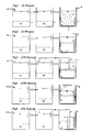
- FIGS. 1 to 5 are vertical sections in the flow direction through the Pool.
- Fig. 1 shows the B phase
- Fig. 2 the V phase
- Fig. 3 the excess sludge withdrawal phase (ÜS)
- Fig. 4 the clear water withdrawal phase
- Fig. 5 the swimming sludge withdrawal phase (SS).
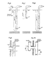
- 6 to 10 show further constructive designs of the KW, ÜS and SS fume cupboards, as well as the closure of the supply line to the biological reactor during the A phase.
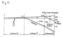
- Fig. 11 shows the reactor contents in temporal course.
- the device shown consists of one that works according to the Einbeckentechnologie biological reactor (1) upstream of which one or more basins (2) are connected, and wherein during the withdrawal of clear water the inflow (3) to the biological Reactor is prevented.
- the ventilation phase is optimal during a day adapted to the wastewater inflow to the sewage treatment plant.
- the automatic surplus and swimming mud vent is also used to balance the concentration during a Day and helps to better bridge the longer load phase of the sewage treatment plant.
- the ÜS deduction takes place automatically in every cycle. At the end of the V phase briefly in a fixed reactor location (approx. 1.2 m below the water level) briefly removed the contents of the reactor and into the upstream Pumped pelvis (about 1 to 2 minutes). Is the sludge level at the pumping time? Above the extraction point, mud is collected, if it is deeper, clear water becomes in the Circulated (see Fig. 3). The ÜS deduction also makes sense with Compressed air.
- the SS deduction is made 1 to 2 minutes at the end of the A phase, if the minimum water level has been reached. (see Figs. 5 and 7).
- the ÜS deduction and the SS deduction also have the important task of Cycle management of the wastewater and thus one To achieve concentration balance between day and night. Even longer ones Interruptions in the load of a sewage treatment plant can be mitigated in this way the pre-clarification of redissolved substances helps to preserve the life of biology.
- the inflow to the reactor may already be on The beginning of the V phase.
- Odor-laden air can occur in the primary clarifier and in the sludge storage. By blowing this air into the biological reactor in the course of aeration this problem can be mitigated or eliminated.
- Municipal wastewater separation system, 150 PE, 60 g BOD5 / PE.
- V phase 1 h; average discharge quantity 11 m 3 / h (lifting capacity)
Abstract
Description
Die Erfindung betrifft ein Verfahren und Einrichtungen zur Reinigung von kommunalem oder ähnlichem Abwasser nach der Einbeckentechnologie.The invention relates to a method and devices for cleaning municipal or similar wastewater using single basin technology.
Das bekannteste Verfahren der Einbeckentechnologie ist - vorwiegend für kleine Kläranlagen - die SBR Technik (sequency batch reactor = stoßweise Beschickung). Am Beginn eines Zyklus wird aus einem Speicherbecken mit einer Pumpe Abwasser in den biologischen Reaktor gepumpt und anschließend der Belüftungs-(B), Vorabsetz- (V) und Abzugsphase (A) unterworfen. Dann beginnt wieder der Belüftungsvorgang. Nachteilig wirkt sich aus, daß Pumpspeicherbecken vorzuschalten sind, die weder einer Entschlammung noch einer Speicherung des Schlammes dienen.The best-known process of single-basin technology is - mainly for small ones Sewage treatment plants - the SBR technology (sequential batch reactor = intermittent feeding). At the beginning of a cycle, a storage tank is turned into a pump Waste water is pumped into the biological reactor and then the aeration (B), Preliminary (V) and withdrawal phase (A) subjected. Then the begins again Ventilation process. A disadvantage is that the pump storage basin is connected upstream are, which neither a desludging nor a storage of the Serve mud.
Erfindungsgemäß werden vorgeschaltete Becken zur Entschlammung des Rohabwassers, die gleichzeitig der Schlammspeicherung dienen, hydraulisch mit dem biologischen Reaktor verbunden, sodaß alle Becken wie kommunizierende Gefäße wirken. Es ist sinnvoll, mindestens zwei solche vorgeschaltete Becken anzuordnen, sodaß im ersten der Primärschlamm (PS) und im zweiten der Überschußschlamm (ÜS) gespeichert werden kann. Der Primärschlamm wird zu einer großen Kläranlage zur weiteren Behandlung gebracht und der Überschußschlamm kann eventuell vor Ort landwirtschaftlich verwendet werden. Mechanische Reinigungseinrichtungen wie Rechen oder Siebe sind nicht erforderlich. Diese Anordnung der Becken hat den Vorteil, daß das in der B- und V-Phase zufließende Abwasser den Wasserspiegel in allen Becken anhebt und somit der Aufstau klein gehalten werden kann.According to the invention, upstream pools for desludging the Raw wastewater, which also serves to store sludge, is hydraulically included connected to the biological reactor, so that all basins are like communicating Vessels work. It makes sense to have at least two such upstream pools to be arranged so that in the first the primary sludge (PS) and in the second the Excess sludge (ÜS) can be stored. The primary sludge becomes too brought to a large sewage treatment plant for further treatment and the excess sludge can possibly be used for agriculture on site. Mechanical Cleaning devices such as rakes or sieves are not required. This Arrangement of the basin has the advantage that the inflowing in the B and V phase Wastewater raises the water level in all pools and thus the build-up is small can be held.
Der Spiegelanstieg erfolgt bis zum Ende der V-Phase in allen Becken. Das in der V-Phase in den Reaktor gelangende entschlammte Rohabwasser ist mengenmäßig gering, wird in den Bodenbereich des Reaktors geführt, dort im Schlammbereich gehalten und gelangt deshalb in der anschließenden A-Phase nicht in den Ablauf. Die V-Phase wird so lange gewählt, bis ein feststofffreier Abzug von Klarwasser möglich ist.The level rises in all pools until the end of the V phase. That in the V-phase raw sewage entering the reactor is in volume low, is led into the bottom area of the reactor, there in the sludge area held and therefore does not get into the sequence in the subsequent A phase. The V-phase is selected until there is a solids-free removal of clear water is possible.
Am Beginn der A-Phase wird der Zufluß zum biologischen Reaktor unterbunden, sodaß jetzt das zufließende Abwasser nur in den Vorbecken aufgefangen wird und dort den Wasserspiegel weiter anhebt. Im biologischen Reaktor wird Klarwasser abgezogen, bis ein vorgegebener minimaler Wasserspiegel erreicht ist. Der Klarwasserabzug erfolgt vorzugsweise mit Hilfe eines Drucklufhebers. Gleichzeitig kann mit der gleichen Druckluft, die den Klarwasserabzug antreibt, der Zulauf zum biologischen Reaktor z. B. durch eine Gummikugel oder einen Gummischlauch unterbunden werden.At the beginning of the A phase, the inflow to the biological reactor is stopped, so that the inflowing wastewater is now only collected in the anteroom and there raises the water level further. Clear water becomes in the biological reactor subtracted until a predetermined minimum water level is reached. The Clear water is preferably drawn off with the aid of a compressed air lifter. At the same time can with the same compressed air that drives the clear water drain, the inlet to biological reactor z. B. by a rubber ball or a rubber hose be prevented.
Um den biologischen Reaktor optimal für die Reinigung des Abwassers nutzen zu können, wird die Belüftungsphase vom Abwasserzulauf in den Reaktor abhängig gemacht. Die Belüftungsphase wird solange betrieben, bis ein vorgegebener Wasserspiegel im Reaktor erreicht wird. Dann beginnt die V-Phase. Für das Abschalten der Belüftung - vorzugsweise wählt man eine feinblasige Druckbelüftung - wird z.B. ein Schwimmerschalter eingesetzt. Zusätzlich wird man die B-Phase zeitlich noch einschränken (z.B. mit 6 Stunden). Für die Elimination von organischen Stoffen des Abwassers und für die Nitrifikation ist das aerobe Schlammalter maßgebend. Der Nachweis der hydraulischen Kapazität erfolgt mit der maximalen Abwassermenge. Für die biochemische Reinigung ist das aerobe Schlammalter der mittleren Wochenbelastung maßgebend. To use the biological reactor optimally for the purification of the wastewater the aeration phase depends on the wastewater feed into the reactor made. The ventilation phase is operated until a predetermined one Water level in the reactor is reached. Then the V phase begins. For the Switching off the ventilation - preferably choose a fine bubble Pressure ventilation - e.g. a float switch is used. In addition one becomes restrict the B phase in time (e.g. with 6 hours). For elimination of organic matter from wastewater and for nitrification is aerobic Decisive sludge age. The hydraulic capacity is verified with the maximum amount of wastewater. This is aerobic for biochemical cleaning Decisive sludge age of the average weekly exposure.
Weitere Einzelheiten der Erfindung werden anschließend anhand der Zeichnungen erläutert. In diesen sind Fig. 1 bis Fig. 5 Vertikalschnitte in Fließrichtung durch die Becken. Fig. 1 zeigt die B-Phase, Fig. 2 die V-Phase, Fig. 3 die Überschußschlammabzugsphase (ÜS), Fig. 4 die Klarwasserabzugsphase (KW) und Fig. 5 die Schwimmschlammabzugsphase (SS). Fig. 6 bis Fig. 10 zeigen weitere konstruktive Ausführungen des KW-, des ÜS- und des SS-Abzuges, sowie des Verschlusses der Zulaufleitung zum biologischen Reaktor während der A-Phase. Fig. 11 zeigt den Reaktorinhalt im zeitlichen Verlauf.Further details of the invention are described below with reference to the drawings explained. In these, FIGS. 1 to 5 are vertical sections in the flow direction through the Pool. Fig. 1 shows the B phase, Fig. 2 the V phase, Fig. 3 the excess sludge withdrawal phase (ÜS), Fig. 4 the clear water withdrawal phase (KW) and Fig. 5 the swimming sludge withdrawal phase (SS). 6 to 10 show further constructive designs of the KW, ÜS and SS fume cupboards, as well as the closure of the supply line to the biological reactor during the A phase. Fig. 11 shows the reactor contents in temporal course.
Die dargestellte Einrichtung besteht aus einem nach der Einbeckentechnologie arbeitenden biologischen Reaktor (1), dem ein oder mehrere Becken (2) vorgeschaltet sind, und wobei während des Abzuges von Klarwasser der Zufluß (3) zum biologischen Reaktor unterbunden wird. Die Belüftungsphase wird während eines Tages optimal dem Abwasserzufluß zur Kläranlage angepaßt. Der automatische Überschuß- und Schwimmschlammabzug dient auch dem Konzentrationsausgleich während eines Tages und hilft, längere Belastungsphase der Kläranlage besser zu überbrücken.The device shown consists of one that works according to the Einbeckentechnologie biological reactor (1) upstream of which one or more basins (2) are connected, and wherein during the withdrawal of clear water the inflow (3) to the biological Reactor is prevented. The ventilation phase is optimal during a day adapted to the wastewater inflow to the sewage treatment plant. The automatic surplus and Swimming mud vent is also used to balance the concentration during a Day and helps to better bridge the longer load phase of the sewage treatment plant.
Der ÜS-Abzug erfolgt automatisch in jedem Zyklus. Am Ende der V-Phase wird kurzzeitig in einer fix vorgegebenen Reaktorstelle (ca. 1,2 m unter dem Wasserspiegel) kurzzeitig Inhalt des Reaktors abgezogen und in die vorgeschalteten Becken gepumpt (ca. 1 bis 2 Minuten). Liegt der Schlammspiegel zur Abpumpzeit über der Abzugsstelle, wird Schlamm erfaßt, liegt er tiefer, wird Klarwasser im Kreislauf geführt (siehe Fig. 3). Der ÜS-Abzug erfolgt sinnvoller Weise auch mit Druckluft.The ÜS deduction takes place automatically in every cycle. At the end of the V phase briefly in a fixed reactor location (approx. 1.2 m below the water level) briefly removed the contents of the reactor and into the upstream Pumped pelvis (about 1 to 2 minutes). Is the sludge level at the pumping time? Above the extraction point, mud is collected, if it is deeper, clear water becomes in the Circulated (see Fig. 3). The ÜS deduction also makes sense with Compressed air.
Der SS-Abzug wird 1 bis 2 Minuten am Ende der A-Phase vorgenommen, wenn der minimale Wasserspiegel erreicht ist. (siehe Fig. 5 und 7).The SS deduction is made 1 to 2 minutes at the end of the A phase, if the minimum water level has been reached. (see Figs. 5 and 7).
Der ÜS-Abzug und der SS-Abzug haben auch die wichtige Aufgabe, eine Kreislauf- führung des Abwassers hervorzurufen und somit einen Konzentrationsausgleich zwischen Tag und Nacht zu erzielen. Auch längere Belastungsunterbrechungen einer Kläranlage können so gemildert werden, da in der Vorklärung rückgelöste Stoffe das Leben der Biologie erhalten helfen.The ÜS deduction and the SS deduction also have the important task of Cycle management of the wastewater and thus one To achieve concentration balance between day and night. Even longer ones Interruptions in the load of a sewage treatment plant can be mitigated in this way the pre-clarification of redissolved substances helps to preserve the life of biology.
Eventuell kann bei besonderen Verhältnissen der Zufluß zum Reaktor schon am Beginn der V-Phase unterbrochen werden.In certain circumstances, the inflow to the reactor may already be on The beginning of the V phase.
Im Vorklärbecken und im Schlammspeicher kann geruchsbelastete Luft auftreten. Durch Einblasen dieser Luft in den biologischen Reaktor im Zuge der Belüftung kann dieses Problem gemildert bzw. beseitigt werden. Odor-laden air can occur in the primary clarifier and in the sludge storage. By blowing this air into the biological reactor in the course of aeration this problem can be mitigated or eliminated.
Kommunales Abwasser: Trennsystem, 150 EW, 60 g BSB5/EW.Municipal wastewater: separation system, 150 PE, 60 g BOD5 / PE.
Qd = 22,5 m3/d; Qmax = 2,25 m3/d; Qm = 22,5 : 24 = 0,94 m3/h
So = 9,0 kg BSB5/d; Zufluß in den biologischen Reaktor 6,0 kg BSB5/dQ d = 22.5 m 3 / d; Q max = 2.25 m3 / d; Q m = 22.5: 24 = 0.94 m 3 / h
S o = 9.0 kg BOD 5 / d; Inflow into the biological reactor 6.0 kg BOD 5 / d
Schlamm: ISV = 150 ml/g; TS = 3,3 g/l; Vs = 1,25 m/h
Fläche der vorgeschalteten Becken: 10 m2
Fläche des biologischen Reaktors: 10 m2
Mind. Wassertiefe: 3,0 mSludge: ISV = 150 ml / g; TS = 3.3 g / l; V s = 1.25 m / h
Area of the upstream pool: 10 m 2
Biological reactor area: 10 m 2
At least Water depth: 3.0 m
B-Phase: tmin = 1,0 h; t max = 6 h; tm = 2,25 : 0,94 = 2,4 hB phase: t min = 1.0 h; t max = 6 h; t m = 2.25: 0.94 = 2.4 h
V-Phase: 1 h; mittlere Abzugsmenge 11 m3/h (Heberleistung)V phase: 1 h; average discharge quantity 11 m 3 / h (lifting capacity)
B-Phase = 1 h; V-Phase = 1 h;
A-Phase; (2h + xh) x 2,25 = 11 x X; X ≅ O,5 h
Vs = Sinkgeschwindigkeit des SchlammspiegelsB phase = 1 h ; V phase = 1 h ;
A phase; (2 h + x h ) x 2.25 = 11 x X; X ≅ O, 5 h
V s = sink rate of the sludge level
Erf. aerobes Schlammalter: 10 Tage (Nitrifikation)
Belastung des biologischen Reaktors: 6,0 kg BSB5/d
Schlammproduktion: 1,0 kg TS/kg BSB5
Belüftungsfaktor des Reaktors: = 2,4 h : (2,4 h + 1,0 h + 0,4 h) = 0,63Erf. aerobic sludge age: 10 days (nitrification)
Biological reactor load: 6.0 kg BOD5 / d
Sludge production: 1.0 kg TS / kg BOD5
Aeration factor of the reactor: = 2.4 h : (2.4 h + 1.0 h + 0.4 h ) = 0.63
Erforderliches Schlammalter SMerf = 6,0 x 1,0 x 10 = 60 kg /TS;
Vorhandenes SchlammalterSMvorh = 30 x 3,3 x 0,63 = 62 kg TS > 60 kg TSRequired sludge age SM erf = 6.0 x 1.0 x 10 = 60 kg / TS;
Existing sludge age SM existing = 30 x 3.3 x 0.63 = 62 kg TS> 60 kg TS
Claims (15)
Priority Applications (1)
| Application Number | Priority Date | Filing Date | Title |
|---|---|---|---|
| EP99109592A EP1052228A1 (en) | 1999-05-14 | 1999-05-14 | Process for cleaning waste water and plant therefore |
Applications Claiming Priority (1)
| Application Number | Priority Date | Filing Date | Title |
|---|---|---|---|
| EP99109592A EP1052228A1 (en) | 1999-05-14 | 1999-05-14 | Process for cleaning waste water and plant therefore |
Publications (1)
| Publication Number | Publication Date |
|---|---|
| EP1052228A1 true EP1052228A1 (en) | 2000-11-15 |
Family
ID=8238176
Family Applications (1)
| Application Number | Title | Priority Date | Filing Date |
|---|---|---|---|
| EP99109592A Withdrawn EP1052228A1 (en) | 1999-05-14 | 1999-05-14 | Process for cleaning waste water and plant therefore |
Country Status (1)
| Country | Link |
|---|---|
| EP (1) | EP1052228A1 (en) |
Cited By (4)
| Publication number | Priority date | Publication date | Assignee | Title |
|---|---|---|---|---|
| WO2003093706A1 (en) * | 2002-05-02 | 2003-11-13 | Kurt Ingerle | Device for regulating the drainage of a liquid |
| EP1582263A1 (en) * | 2004-04-02 | 2005-10-05 | Uponor Innovation Ab | Pressurized air lifting device for flowable materials |
| RU2565063C2 (en) * | 2009-07-17 | 2015-10-20 | Эро КАУТИА | Method of biological treatment |
| CN105967459A (en) * | 2016-07-18 | 2016-09-28 | 江超 | Sequencing batch reactor (SBR) water purification technology and operation method thereof |
Citations (6)
| Publication number | Priority date | Publication date | Assignee | Title |
|---|---|---|---|---|
| US3522881A (en) * | 1968-01-25 | 1970-08-04 | Drysdale & Co Ltd | Apparatus for the treatment of sewage and like industrial waste |
| DE2845312A1 (en) * | 1976-09-23 | 1980-04-30 | Bernard Caillot | Packaged treatment plant for aerating and decanting waste water - uses air ejector to discharge purified effluent without disturbing settled sludge |
| EP0339013A2 (en) * | 1986-12-22 | 1989-10-25 | STOISER & WOLSCHNER Alleininhaber Dipl.-Ing. Heinz Wolschner SW-span-Kläranlagen-Umwelttechnik | Apparatus for waste water treatment |
| US5013441A (en) * | 1988-07-20 | 1991-05-07 | Goronszy Mervyn C | Biological nutrient removal with sludge bulking control in a batch activated sludge system |
| EP0466973A1 (en) * | 1990-07-17 | 1992-01-22 | SI-tronik Schäfer GmbH | Process and apparatus for biological clarification of water by aerobic sludge stabilisation, especially in small clarification plants |
| DE19816076A1 (en) * | 1997-04-14 | 1998-10-15 | Aratec Planungs Und Vertriebsg | Water treatment plant comprises pre-treatment and activated sludge treatment basins |
-
1999
- 1999-05-14 EP EP99109592A patent/EP1052228A1/en not_active Withdrawn
Patent Citations (6)
| Publication number | Priority date | Publication date | Assignee | Title |
|---|---|---|---|---|
| US3522881A (en) * | 1968-01-25 | 1970-08-04 | Drysdale & Co Ltd | Apparatus for the treatment of sewage and like industrial waste |
| DE2845312A1 (en) * | 1976-09-23 | 1980-04-30 | Bernard Caillot | Packaged treatment plant for aerating and decanting waste water - uses air ejector to discharge purified effluent without disturbing settled sludge |
| EP0339013A2 (en) * | 1986-12-22 | 1989-10-25 | STOISER & WOLSCHNER Alleininhaber Dipl.-Ing. Heinz Wolschner SW-span-Kläranlagen-Umwelttechnik | Apparatus for waste water treatment |
| US5013441A (en) * | 1988-07-20 | 1991-05-07 | Goronszy Mervyn C | Biological nutrient removal with sludge bulking control in a batch activated sludge system |
| EP0466973A1 (en) * | 1990-07-17 | 1992-01-22 | SI-tronik Schäfer GmbH | Process and apparatus for biological clarification of water by aerobic sludge stabilisation, especially in small clarification plants |
| DE19816076A1 (en) * | 1997-04-14 | 1998-10-15 | Aratec Planungs Und Vertriebsg | Water treatment plant comprises pre-treatment and activated sludge treatment basins |
Cited By (4)
| Publication number | Priority date | Publication date | Assignee | Title |
|---|---|---|---|---|
| WO2003093706A1 (en) * | 2002-05-02 | 2003-11-13 | Kurt Ingerle | Device for regulating the drainage of a liquid |
| EP1582263A1 (en) * | 2004-04-02 | 2005-10-05 | Uponor Innovation Ab | Pressurized air lifting device for flowable materials |
| RU2565063C2 (en) * | 2009-07-17 | 2015-10-20 | Эро КАУТИА | Method of biological treatment |
| CN105967459A (en) * | 2016-07-18 | 2016-09-28 | 江超 | Sequencing batch reactor (SBR) water purification technology and operation method thereof |
Similar Documents
| Publication | Publication Date | Title |
|---|---|---|
| EP1919833B1 (en) | Waste water purifying device | |
| DE3925091C2 (en) | ||
| Krofta et al. | Wastewater treatment by a biological-physicochemical two-stage process system | |
| EP1531123B1 (en) | Method and installation for the treatment of soiled water from ships | |
| EP0851844B1 (en) | Process for purifying waste water | |
| EP1110916A1 (en) | Process for the biological treatment of waste water | |
| EP0893413B1 (en) | Process and device for the biological treatment of liquids, in particular for the complete biological clarification of waste water | |
| EP1052228A1 (en) | Process for cleaning waste water and plant therefore | |
| DE4307288A1 (en) | Process for biological wastewater treatment with integrated buffering | |
| EP1627854A1 (en) | Method for direct selection of a predetemined low sludge index in a Sequencing Batch Reactor system | |
| DE10127554B4 (en) | Process for the biological purification of waste water | |
| EP0764611A2 (en) | Small clarification plant for domestic waste waters | |
| CN101108760B (en) | Continuous Microfiltration processing technique of regenerated water | |
| DE4332815A1 (en) | Sewage treatment plant operating by the SBR principle | |
| EP0961760B1 (en) | Device for carrying out a method for cleaning waste-water | |
| EP1132348B1 (en) | Installation and process for purification of waste water | |
| DE10123152B4 (en) | Biological wastewater treatment plant for municipal, commercial and agricultural wastewater and process for operating the plant | |
| EP1388524A1 (en) | Discontinuous sewage treatment process and small installation for carrying out this process | |
| DE2255703A1 (en) | MECHANICAL-BIOLOGICAL WASTE WATER PURIFICATION PLANT | |
| EP1072559A2 (en) | Device for wastewater purification | |
| DE10002910A1 (en) | Optimal extraction of purified wastewater from treatment plants with sequencing batch reactors is accomplished by displacement from below | |
| DE10039984A1 (en) | Waste water cleaning installation comprises process chamber provided with means serving for performance of various functions which jointly constitute the required water cleaning process | |
| DE2500616A1 (en) | METHOD FOR BIOLOGICAL PURIFICATION OF WASTE WATER | |
| DE19822289C5 (en) | Method of removing sewage sludge from a sewage pond | |
| WO1998015502A1 (en) | Method for sewage treatment in small treatment plants |
Legal Events
| Date | Code | Title | Description |
|---|---|---|---|
| PUAI | Public reference made under article 153(3) epc to a published international application that has entered the european phase |
Free format text: ORIGINAL CODE: 0009012 |
|
| AK | Designated contracting states |
Kind code of ref document: A1 Designated state(s): AT DE ES GR IT |
|
| AX | Request for extension of the european patent |
Free format text: AL;LT;LV;MK;RO;SI |
|
| 17P | Request for examination filed |
Effective date: 20010426 |
|
| AKX | Designation fees paid |
Free format text: AT DE ES GR IT |
|
| STAA | Information on the status of an ep patent application or granted ep patent |
Free format text: STATUS: THE APPLICATION IS DEEMED TO BE WITHDRAWN |
|
| 18D | Application deemed to be withdrawn |
Effective date: 20031201 |