EP1052497A2 - Cover glass adhering device - Google Patents
Cover glass adhering device Download PDFInfo
- Publication number
- EP1052497A2 EP1052497A2 EP00303853A EP00303853A EP1052497A2 EP 1052497 A2 EP1052497 A2 EP 1052497A2 EP 00303853 A EP00303853 A EP 00303853A EP 00303853 A EP00303853 A EP 00303853A EP 1052497 A2 EP1052497 A2 EP 1052497A2
- Authority
- EP
- European Patent Office
- Prior art keywords
- glass
- mounting medium
- drop
- cover glass
- slide
- Prior art date
- Legal status (The legal status is an assumption and is not a legal conclusion. Google has not performed a legal analysis and makes no representation as to the accuracy of the status listed.)
- Granted
Links
- 239000006059 cover glass Substances 0.000 title claims abstract description 138
- 239000011521 glass Substances 0.000 claims abstract description 151
- 239000012120 mounting media Substances 0.000 claims abstract description 113
- 239000002904 solvent Substances 0.000 claims description 21
- 230000003028 elevating effect Effects 0.000 claims description 10
- 238000007711 solidification Methods 0.000 claims description 10
- 230000008023 solidification Effects 0.000 claims description 10
- 238000005452 bending Methods 0.000 description 2
- 238000000926 separation method Methods 0.000 description 2
- 238000004043 dyeing Methods 0.000 description 1
- 238000004519 manufacturing process Methods 0.000 description 1
- 238000000034 method Methods 0.000 description 1
Images


Classifications
-
- G—PHYSICS
- G02—OPTICS
- G02B—OPTICAL ELEMENTS, SYSTEMS OR APPARATUS
- G02B21/00—Microscopes
- G02B21/34—Microscope slides, e.g. mounting specimens on microscope slides
-
- G—PHYSICS
- G01—MEASURING; TESTING
- G01N—INVESTIGATING OR ANALYSING MATERIALS BY DETERMINING THEIR CHEMICAL OR PHYSICAL PROPERTIES
- G01N1/00—Sampling; Preparing specimens for investigation
- G01N1/28—Preparing specimens for investigation including physical details of (bio-)chemical methods covered elsewhere, e.g. G01N33/50, C12Q
- G01N1/30—Staining; Impregnating ; Fixation; Dehydration; Multistep processes for preparing samples of tissue, cell or nucleic acid material and the like for analysis
- G01N1/31—Apparatus therefor
- G01N1/312—Apparatus therefor for samples mounted on planar substrates
-
- Y—GENERAL TAGGING OF NEW TECHNOLOGICAL DEVELOPMENTS; GENERAL TAGGING OF CROSS-SECTIONAL TECHNOLOGIES SPANNING OVER SEVERAL SECTIONS OF THE IPC; TECHNICAL SUBJECTS COVERED BY FORMER USPC CROSS-REFERENCE ART COLLECTIONS [XRACs] AND DIGESTS
- Y10—TECHNICAL SUBJECTS COVERED BY FORMER USPC
- Y10T—TECHNICAL SUBJECTS COVERED BY FORMER US CLASSIFICATION
- Y10T156/00—Adhesive bonding and miscellaneous chemical manufacture
- Y10T156/17—Surface bonding means and/or assemblymeans with work feeding or handling means
- Y10T156/1702—For plural parts or plural areas of single part
- Y10T156/1744—Means bringing discrete articles into assembled relationship
- Y10T156/1751—At least three articles
- Y10T156/1761—Stacked serially
-
- Y—GENERAL TAGGING OF NEW TECHNOLOGICAL DEVELOPMENTS; GENERAL TAGGING OF CROSS-SECTIONAL TECHNOLOGIES SPANNING OVER SEVERAL SECTIONS OF THE IPC; TECHNICAL SUBJECTS COVERED BY FORMER USPC CROSS-REFERENCE ART COLLECTIONS [XRACs] AND DIGESTS
- Y10—TECHNICAL SUBJECTS COVERED BY FORMER USPC
- Y10T—TECHNICAL SUBJECTS COVERED BY FORMER US CLASSIFICATION
- Y10T156/00—Adhesive bonding and miscellaneous chemical manufacture
- Y10T156/17—Surface bonding means and/or assemblymeans with work feeding or handling means
- Y10T156/1785—Magazine stack directly contacting work
Landscapes
- Physics & Mathematics (AREA)
- Life Sciences & Earth Sciences (AREA)
- Analytical Chemistry (AREA)
- General Physics & Mathematics (AREA)
- Chemical & Material Sciences (AREA)
- Health & Medical Sciences (AREA)
- Biomedical Technology (AREA)
- Engineering & Computer Science (AREA)
- Optics & Photonics (AREA)
- Molecular Biology (AREA)
- Biochemistry (AREA)
- General Health & Medical Sciences (AREA)
- Immunology (AREA)
- Pathology (AREA)
- Microscoopes, Condenser (AREA)
- Sampling And Sample Adjustment (AREA)
Abstract
Description
- The present invention relates to a cover glass adhering device, more precisely relates to a cover glass adhering device, which mounts a cover glass onto a mounting medium covering a microscope specimen on a slide glass.
- A method of making a microscope specimen, e.g., a tissue slice of an affected part of a patient, is shown in Fig. 17. The method comprising the steps of: slicing a tissue of the affected part; mounting the
tissue slice 10 onto aslide glass 12; removing fat from thetissue slice 10; dyeing thetissue slice 10; dropping a mounting medium, which includes a solvent, onto thetissue slice 10 on theslide glass 12; and mounting acover glass 16 onto amounting medium pattern 140, which is formed by dropping the mounting medium along thetissue slice 10. The solvent in the mounting medium evaporates, and the mounting medium solidifies, so that thecover glass 16 is adhered on theslide glass 12. - For example, in hospitals, a lot of microscope specimens must be made in a short time.
- To automatically make the microscope specimens, a dropping device (see Fig. 18), which automatically drops the mounting medium onto the
specimens 10 on theslide glasses 12, was disclosed in the Japanese Patent Gazettes No. 59-157533 and No. 61-66141. In Fig. 18, compressed air, which is compressed by acompressor 102, is introduced into an upper inner space of acontainer 100, in which the mounting medium including the solvent is reservoired, via aregulator 106 of a pressurizingpipe 104. The mounting medium in thecontainer 100 is pushed and sent, by the compressed air in thecontainer 100, to atank 112 via a spoutingpipe 108, whose one end is opened in a lower part of thecontainer 100. The mounting medium in thetank 112 is dropped onto the specimen on theslide glass 12 from adrop nozzle 114. Amount of dropping the mounting medium can be controlled by acontrol valve 110, which opens and closes with regular time separations. A table 116, on which theslide glass 12 is mounted, is slid in a direction of an arrow, so that the mounting medium can be dropped along thespecimen 10 and themounting medium pattern 140 having the prescribed pattern can be formed. - Usually, a plurality of
cover glasses 16, each of which will covers thespecimen 10 on theslide glass 12, are piled in a holder container. Thus, theuppermost glass 16 of the piled cover glasses must be taken out from the holder container. - The
cover glass 16 has a thickness of 0.06-0.25 mm and flat surfaces, so the piledcover glasses 16 are mutually tightly fitted. - A device for taking out the uppermost cover glass of the piled
cover glasses 16 from a holder container was disclosed in the Japanese Patent Gazette No. 58-30636. The device is shown in Fig. 19. - In the device shown in Fig. 19, a
press member 204 is pierced through anelevating member 202, which can be moved in the vertical direction, and itslower end 205 is biased downward by aspring 203. A suckingpad 206 is provided to theelevating member 202. To take out theuppermost cover glass 16a of the piledcover glasses 16 in aholder container 200, theelevating member 202 is moved downward to push one end of theuppermost glass 16a by thelower end 205 of thepress member 204, and the other end of theuppermost glass 16a is pulled upward by the suckingmember 206 of theelevating member 202. At that time, an upper end of thepress member 204 is projected upward, against the elasticity of thespring 203, from theelevating member 202. - Next, the
elevating member 202 is moved upward as shown in Fig. 19. With this action, the other end of thecover glass 16a is pulled upward by thesucking member 206, and thecover glass 16a is bent downward, so that thecover glass 16a can be removed from thepiled glasses 16 and taken out from theholder container 200. - A device for mounting and adhering the
cover glass 16, which has been taken out from theholder container 200, onto themounting medium pattern 140, which has been formed on theslide glass 12 by dropping the mounting medium, was disclosed in the Japanese Patent Gazette No. 3-40367. The device is shown in Fig. 20. - In the device shown in Fig. 20, a
press member 306 is pierced through aholder member 300, which can be moved in the vertical direction, and itslower end 304 is biased downward by aspring 302. A suckingpad 308 is provided to theholder member 300. To mount and adhere thecover glass 16 onto themounting medium pattern 140, which includes thespecimen 10 and which is formed on theslide glass 12 by dropping the mounting medium, one end of thecover glass 16 is sucked by thesucking pad 308. At that time, the other end of thecover glass 16 is pushed downward by thelower end 304 of thepress member 306, so that the other end of thecover glass 16 is located below the one end thereof. - Next, the
holder member 300 is moved downward and toward theslide glass 12, which has been horizontally mounted on a table 310, until the other end of thecover glass 16 contacts an upper face of one end of theslide glass 12. With further moving theholder member 300 downward, the one end of thecover glass 16 is gradually moved toward the upper face of theslide glass 12. With this action, thecover glass 16 pushes themounting medium pattern 140 toward the other end of theslide glass 12 and tightly fits thereon, so that air bubbles between theslide glass 12 and thecover glass 16 can be pushed out by thecover glass 16. - Upon completing or immediately before completing the action of mounting the
cover glass 16, thesucking pad 308 releases thecover glass 16 and theholder member 300 is moved upward, so that thecover glass 12 can be left on theslide glass 12. - The inventors of the present invention have studied a cover glass adhering device, which includes a unit for taking out the cover glass and a unit for mounting the cover glass, so as to automatically make a microscope specimen.
- In the cover glass adhering device, the sequential steps for adhering the cover glass onto a specimen on a slide glass can be executed automatically.
- However, the cover glass adhering device has following disadvantages: it is difficult to always drop fixed amount of mounting medium onto the specimen; it is difficult to always form a mounting medium pattern into a prescribed pattern; the device must be large in size; and a long cover glass cannot be used.
- It would be desirable to provide a cover glass adhering device, which is capable of dropping fixed amount of mounting medium, using cover glasses having various length, and being small in size.
- The inventors have studied and found: the size of the device can be smaller than that of the conventional device, in which the slide glass is slid, by sliding a drop nozzle; and fixed amount of the mounting medium can be supplied by using a proper supply unit for supplying fixed amount of the mounting medium, e.g., a plunger pump, and removing a drop of the mounting medium dangling from said drop nozzle.
- And, they found that mounting medium patterns can be always formed into a prescribed pattern by the steps of: stopping a movement of the drop nozzle at a position, at which the drop action of the mounting medium is begun; beginning the drop action thereof; and moving the drop nozzle along the slide glass.
- Further, they found that a rotational angle of a holding member, which holds one end of the uppermost cover glass of a plurality of cover glasses, can be made narrower by slantingly piling the cover glasses in a holder container.
- The cover glass adhering device of the present invention, which mounts a cover glass onto a mounting medium covering a microscope specimen on a slide glass,
comprises: - a drop nozzle for dropping the mounting medium onto the specimen on a slide glass, which is held horizontally;
- a removing member for removing a drop of the mounting medium dangling from the drop nozzle, the removing member being located outside of the slide glass; and
- a traveling unit for traveling the drop nozzle, from which the dangling drop of the mounting medium has been removed by the removing member, along the specimen on the slide glass so as to drop a prescribed amount of the mounting medium over the specimen.
-
- Another cover glass adhering device of the present invention, which mounts a cover glass onto a mounting medium covering a microscope specimen on a slide glass,
comprises: - a holding member being capable of holding one end of an uppermost glass of the cover glasses, which have been slantingly piled in a holder container;
- a rotary unit for turning the holding member so as to downwardly bend the uppermost glass and remove the same from the adjacent cover glass; and
- a vertical drive unit for vertically moving the holding member and the rotary unit.
-
- Further, the cover glass adhering device of the present invention,
comprises: - means for conveying a slide glass, the conveying means being provided between a basket container, in which a plurality of slide glasses, on each of which a microscope specimen is mounted, are accommodated, and a rack, in which the slide glasses, on each of which a cover glass is mounted to cover the specimen, will be accommodated, the conveying means having a conveyor plate, which intermittently conveys the slide glass, which is horizontally held, toward the rack;
- means for taking out the slide glass from the basket container and horizontally putting the slide glass onto a predetermined position in the conveyor plate;
- means for dropping a mounting medium, the dropping means including:
- a drop nozzle dropping the mounting medium onto the specimen on the slide glass, which has been horizontally conveyed to a predetermined position by the conveying means;
- a traveling unit for traveling the drop nozzle along the specimen on the slide glass so as to drop a prescribed amount of the mounting medium supplied by a supply unit, which is capable of supplying the prescribe amount of the mounting medium, over the specimen; and
- a control section for controlling the traveling unit and the supply unit so as to stop the movement of the drop nozzle at a start end, at which the drop nozzle starts to drop the mounting medium onto the slide glass and move the drop nozzle along the slide glass after starting the drop action; and
- means for holding and adhering the cover glass, the holding-and-adhering
means including:
- a holding member being capable of holding one end of an uppermost glass of the cover glasses, which have been slantingly piled in a holder container;
- a take-out unit turning the holding member so as to downwardly bend the uppermost glass and remove the same from the adjacent cover glass, then taking out the uppermost glass from the holder container; and
- a mounting unit gradually mounting the cover glass, whose one end is held by the holding member, onto the mounting medium, which covers the specimen on the slide glass conveyed to a predetermined position, from the other end to the one end.
-
- In the cover glass adhering device, the traveling unit may include:
- an elevating unit for moving the drop nozzle in the vertical direction; and
- a sliding unit for sliding the drop nozzle along the specimen on the slide glass until a position outside of the slide glass. With this structure, the drop nozzle can be smoothly moved to the position out of the slide glass.
-
- The cover glass adhering device may further comprise a container, in which a solvent for preventing solidification of the mounting medium is reservoired, being located at a position, which is outside of the slide glass and at which a front end of the drop nozzle can enter the container. With this structure, closing the drop nozzle can be prevented even if the device is stopped for a long time.
- In the cover glass adhering device, the control section of the dropping means may control the movement of the traveling unit so as to put the front end of the drop nozzle into a container, in which a solvent for preventing solidification of the mounting medium is reservoired, before dropping the mounting medium, while stopping or after the dropping action. With this structure, closing the drop nozzle can be prevented even if the device is stopped for a long time.
- In the cover glass adhering device, the holding-and-adhering means may comprise:
- a sucking member being capable of sucking the one end of the uppermost glass of the cover glasses, which have been slantingly piled in the holder container;
- a rotary unit for turning the sucking member so as to make the other end of the uppermost glass contact with an inner face of the holder container and bend the uppermost glass; and
- a pin being provided in the vicinity of the sucking member, the pin downwardly pushing the uppermost glass, which is bent, so as to deform the uppermost cover glass into an S-shape. With this structure, long cover glasses can be easily taken out from the holder container.
-
- In the cover glass adhering device, the control section of the dropping means may control the traveling unit and the supply unit so as to stop the travel of the drop nozzle, which is moved along the slide glass, after stopping the drop action. With this structure, no air bubbles are left in the mounting medium when the cover glass is mounted on the slide glass.
- In the cover glass adhering device, a supporting section of the rack, in which the slide glasses are accommodated, may have a inclined face, with which side faces of the slide glasses come into contact. With this structure, the mounting medium stuck on the side faces of the piled slide glasses will not be stuck on the rear faces thereof.
- Embodiments of the present invention will now be described by way of examples and with reference to the accompanying drawings, in which:
- Fig. 1 is a perspective view of a cover glass adhering device of an embodiment of the present invention;
- Fig. 2 is a front view of an operation panel of the device shown in Fig. 1;
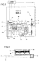
- Fig. 3 is an explanation view of the device shown in Fig. 1;
- Fig. 4 is an explanation view of a basket container shown in Fig. 3;
- Fig. 5 is a partial sectional view of a rack shown in Fig. 3;
- Fig. 6 is a partial perspective view of the device shown in Fig. 1;
- Fig. 7 is an explanation view of means for dropping mounting medium of the device shown in Fig. 1;
- Fig. 8 is a partial perspective view of the dropping means of the device shown in Fig. 1;
- Fig. 9 is a perspective view of a holder container.
- Fig. 10 is an explanation view of means for holding and adhering the cover glass of the device shown in Fig. 1;
- Figs. 11A-11C are explanation views showing a series of action of the dropping means;
- Fig. 12 is an enlarged view of a part "A" showing in Fig. 11C;
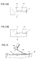
- Figs. 13A and 13B are plan views of a mounting medium pattern, which is formed by the steps shown in Figs. 11A-11C;
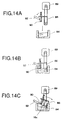
- Figs. 14A-14C are explanation views showing a series of action of taking out the cover glass by the holding-and-adhering means shown in Fig. 10;
- Fig. 15 is an explanation view showing action of mounting the cover glass onto the slide glass by the holding-and-adhering means shown in Fig. 10;
- Fig. 16 is an explanation view showing action of entering a front end of a drop nozzle into a container of solvent, which is located outside of the slide glass and within a moving range of the drop nozzle;
- Fig. 17 is an explanation view showing how to make a microscope specimen;
- Fig. 18 is an explanation view of a conventional drop nozzle;
- Fig. 19 is an explanation view of conventional means for taking out the cover glass; and
- Fig. 20 is an explanation view of conventional means for mounting the cover glass.
-
- Preferred embodiments of the present invention will now be described in detail with reference to the accompanying drawings.
- The cover glass adhering device of the present embodiment of the present invention is shown in Fig. 1. The cover glass adhering device has a
transparent cover 22 for opening and closing abody section 20, and thebody section 20 has anoperating panel 24. Further, acontainer 26, in which mounting medium is reservoired, is inserted in thebody section 20. As shown in Fig. 2, ascreen 28, on which operating conditions are shown, start and stop buttons for each operation, a check button, etc. are provided in theoperating panel 24. An adjustingdial 30 for adjusting amount of supplying the mounting medium and aspeed adjusting dial 32 for adjusting speed of mounting the cover glasses are also provided in theoperating panel 24. - As shown in Fig. 3, a
basket container 34, in which a plurality of slide glasses on each of which a specimen is mounted are accommodated, and racks 36, which store the slide glasses on each of which the cover glass is adhered, are provided in thebody section 20 shown in Fig. 1. - As shown in Fig. 4, a plurality of
baskets 38, in each of which a plurality of the slide glasses on which the specimens are mounted are vertically stored, are provided in thebasket container 34. Thebasket container 34 can be moved by awire 42, which is driven by amotor 40. Theracks 36 are capable of moving in the vertical direction, by amotor 37, so as to store the slide glasses in order. As shown in Fig. 5, supportingsections 44, which support both ends of theslide glasses 12, are formed in slide glass accommodating sections of theracks 36. Front ends 46 of the supportingsections 44 are formed into an L-shape so as to prevent theslide glasses 12 from falling down. Further,inner parts 48 of the supportingsections 44 are slopes. With the slopes, even if side faces of theslide glasses 12, which have been mounted on the supportingsections 44, contact theinner parts 48, the mounting medium stuck on the side faces of theslide glasses 12 will not be sent to the rear faces of theslide glasses 12 via gaps between the side faces of theslide glasses 12 and theinner parts 48 of the supportingsections 44. - A conveying
means 60, which intermittently conveys theslide glasses 12, which is taken from thebasket 38 by slide glass take-out means 50, to theracks 36, is provided between thebasket container 34 and theracks 36. - The slide glass take-out means 50 includes: a
motor 54 for vertically moving amember 53, to which a suckingpad 52 for sucking one end of theslide glass 12, which has been vertically stored in thebasket 38, is fixed; and aweight 56. As shown in Fig. 6, aguide rod 55, which is guided by aguide groove 57 formed in an inner face of thebody section 20, is provided to themember 53 so as to rotate the suckingpad 52. The suckingpad 52 is rotated so as to horizontally arrange theslide glass 12, whose one end has been sucked by the suckingpad 52 and vertically pulled upward. - Note that, the sucking
pad 52 is connected to one end of a hose whose the other end is connected to vacuum means. - The
slide glass 12, which has been horizontally arranged, is located in the vicinity of the take-out means 50, then mounted onto a recessedfirst station 62a of a supportingmember 62, which is capable of supporting both ends of theslide glass 12. In the supportingmember 62, a recessedsecond station 62b, a recessedthird station 62c and a recessedfourth station 62d are further formed, toward theracks 36, with regular separations. - The
slide glass 12 which is horizontally mounted on thefirst station 62a is conveyed to thesecond station 62b, thethird station 62c and thefourth station 62d, in order, by a conveyingplate 64 of the conveyingmeans 60. A plurality ofrecesses 64a are formed in an upper face of the conveyingplate 64 and arranged from the take-out means 50 side to theracks 36 side. A projectedsection 65 is downwardly projected from a bottom face of the conveyingplate 64. The projectedsection 65 is connected to abelt 69, which is engaged with apulley 67, which is directly driven by amotor 66, andfree pulleys section 65 is vertically moved by acam 71, which is driven by amotor 70. With this structure, the conveyingplate 64 is moved upward at a predetermined position and horizontally moved in a predetermined direction, then the conveyingplate 64 is moved downward at a predetermined position and horizontally moved in the reverse direction. - As shown in Fig. 3, the
motors control section 1. By thecontrol section 1, theslide glass 12, which has been horizontally mounted on thefirst station 62a by the take-out means 50, is moved to a position above the supportingmember 62 by the conveyingplate 64, and theslide glass 12 is horizontally conveyed, in the same state, to a position above thesecond station 62a, then theslide glass 12 is moved downward, by the conveyingplate 64, so that theslide glass 12 can be horizontally mounted on thesecond station 62b. The conveyingplate 64, which has been moved downward, is horizontally moved toward thefirst station 62a so as to convey thenext slide glass 12. As described above, theslide glass 12 can be conveyed to the rest stations and stored in theracks 36 in order. - As shown in Fig. 6, the
second station 62b is located in the vicinity of adrop nozzle 72 for dropping the mounting medium; thethird station 62c is located in the vicinity of a suckingpad 90 for sucking the cover glass. - As shown in Fig. 7, means for dropping the mounting medium includes: the
drop nozzle 72; a connectingmember 73a, whose one end is connected to thedrop nozzle 72; amotor 73, which constitutes a slide unit for horizontally sliding thedrop nozzle 72 and which is connected to the other end of the connectingmember 73a; and asolenoid 74, which constitutes an elevating unit for vertically moving thedrop nozzle 72 and whoserod 74a is connected to a mid part of the connectingmember 73a. Themotor 73 and thesolenoid 74 are controlled by acontrol section 2. Thecontrol section 2 moves thedrop nozzle 72 in the horizontal direction and the vertical direction. Aplunger pump 76, which is an example of a supply unit for supplying fixed amount of the mounting medium, supplies the mounting medium from thecontainer 26 to thedrop nozzle 72. Amotor 76b for moving aplunger 76a of theplunger pump 76 is also controlled by thecontrol section 2. - The
drop nozzle 72 is capable of dropping the mounting medium onto theslide glass 12, which has been horizontally arranged, by horizontally moving in the longitudinal direction of theslide glass 12. Theplunger pump 76 is capable of always supplying the fixed amount of the mounting medium. - The
drop nozzle 72 shown in Fig. 6 is capable of horizontally moving to a position outside of theslide glass 12. Adischarge tray 78 and acontainer 80, in which a solvent for preventing solidification of the mounting medium is reservoired, are located at positions, which are outside of theslide glass 12 and within a moving range of thedrop nozzle 72. As shown in Fig. 8, a removingmember 82, which is capable of removing a drop of the mounting medium dangling from thedrop nozzle 72, is vertically extended from thedischarge tray 78. - Check
valves container 26 and thedrop nozzle 72. - As shown in Fig. 6, a sucking
pad 90 for sucking the cover glass and aholder container 84, in which a plurality ofcover glasses 16 are piled, are provided in the vicinity of thethird station 62c. Theholder container 84 is mounted on a container table 85, which is capable of horizontally rotating. Thecover glasses 16 are slantingly piled in theholder container 84. Theuppermost cover glass 16a is taken out from theholder container 84 by the suckingpad 90, which acts as a holding member. - The sucking
pad 90 constitutes means for holding and adhering the cover glass 16 (see Fig. 10). The holding-and-adhering means further includes: anarm 86 in which the suckingpad 90 is provided to one end; amotor 87 for rotating thearm 86 about anaxis 86a; and amotor 89 for vertically moving anarm member 88, to which thearm 86 is attached. Further, thearm member 88 has apin 92, which is provided in the vicinity of the suckingpad 90. Themotors control section 3. - Note that, the sucking
pad 90 is connected to one end of a hose whose the other end is connected to the vacuum means. - By the dropping means shown in Figs. 7 and 8, the
slide glass 12, which is horizontally located on thefirst station 62a, is conveyed to thesecond station 62b by the conveyingplate 64 so as to drop the mounting medium onto a specimen on theslide glass 12. This action is controlled by thecontrol section 2, which controls thesolenoid 74 and themotors - The action of the dropping means shown in Figs. 7 and 8 will be explained with reference to Figs. 11A-11C.
- The
drop nozzle 72 drops the mounting medium onto the specimen on theslide glass 12 and is moved, in the longitudinal direction of theslide glass 12, away from thedischarge tray 78, which is located outside of the slide glass, by themotor 73, which is provided to the other end of the connectingmember 73a whose one end is connected to thedrop nozzle 72, and thesolenoid 74, which is connected to the mid pan of the connectingmember 73a (see Fig. 11A). When thedrop nozzle 72 reaches a predetermined position on theslide glass 12, supplying the mounting medium by theplunger pump 76 and the travel of thedrop nozzle 72 in the longitudinal direction of theslide glass 12 are stopped. Then thedrop nozzle 72 are moved upward and moved toward the discharge tray 78 (Fig. 11B). When thedrop nozzle 72 reaches thedischarge tray 78, thedrop nozzle 72 is moved downward again and moved away from the discharge tray 78 (see Fig. 11C). - As shown in Fig. 12, which is an enlarged view of a part "A" of Fig. 11C, a drop "B" of the mounting medium, which is reservoired in the
drop nozzle 72, is apt to dangle from a lower end of thedrop nozzle 72, which has been stopped. If thedrop nozzle 72, which holds the drop "B", restarts to drop the mounting medium, amount of the mounting medium dropped on theslide glasses 12 are varied. To drop fixed amount of the mounting medium, the lower end of thedrop nozzle 72 is passed over the removingmember 82, which is vertically extended from thedischarge tray 78, so as to make the drop "B" contact the removingmember 82 and remove the drop "B" from thedrop nozzle 72. - After removing the drop "B", the
drop nozzle 72 restarts to drop the mounting medium at a predetermined position on theslide glass 12, so that the fixed amount of the mounting medium can be dropped onto theslide glass 12. - Amount of supplying the mounting medium can be adjusted by the adjusting
dial 30 of the operating panel 24 (see Fig. 2). - In Figs. 11A-11C and 12, the drop "B" of the mounting medium is removed from the lower end of the
drop nozzle 72, and the drop action of thedrop nozzle 72 is started when thedrop nozzle 72 reaches the predetermined position on theslide glass 12. On the other hand, the drop action of thedrop nozzle 72 and the travel of thedrop nozzle 72, in the longitudinal direction of theslide glass 12, are stopped when thedrop nozzle 72 reaches another predetermined position on theslide glass 12. Then thedrop nozzle 72 is moved upward. - With the drop action and the travel of the
drop nozzle 72, a mounting medium pattern 14' shown in Fig. 13B is sometimes formed. A start end "C" of the pattern 14', at which the drop action is started, is narrow; A stop end "D" of the pattern 14', at which the drop action is stopped, is formed like a wide bump. With the pattern shape shown in Fig.13B, air is apt to invade into a space between thecover glass 16 and theslide glass 12 when thecover glass 16 is mounted onto the pattern 14'. - By starting and stopping the drop action and the travel of the
drop nozzle 72 simultaneously, the pattern 14' is formed. Namely, at the start end "C", the mounting medium is begun to be dropped and traveled simultaneously, so that the shape of the start end "C" is formed narrower. - On the other hand, at the stop end "D", the drop action and the travel of the mounting medium is stopped simultaneously, so that the final drop of the mounting medium falls onto the stop end "D" and the shape thereof is formed like a circular wide bump.
- To avoid forming the mounting medium pattern 14' shown in Fig. 13B, the
control section 2 controls thesolenoid 74 and themotor 73, which move thedrop nozzle 72 in the predetermined direction, and themotor 76b, which drives theplunger pump 76 for sending the mounting medium to thedrop nozzle 72, so as to execute the steps of: once stopping the travel of thedrop nozzle 72 at the start end, at which the mounting medium is begun to be dropped onto theslide glass 12; beginning to drop the mounting medium; and starting to travel thedrop nozzle 72 along the surface of theslide glass 12. With this action, the start end "C" of the mounting medium pattern can be wide as shown in Fig. 13A. - On the other hand, the
control section 2 controls thesolenoid 74 and themotors drop nozzle 72 after the drop action is stopped. With this action, the stop end "D" of the mounting medium pattern can be narrower as shown in Fig. 13A. - With the shape of the mounting
medium pattern 14 shown in Fig. 13A, air is not apt to invade in the space between thecover glass 16 and theslide glass 12 when thecover glass 16 is mounted onto thepattern 14 from the start end "C". - The
slide glass 12, on which the mounting medium is dropped at thesecond station 62b, is conveyed to thethird station 62c by the conveyingplate 64. Thecover glass 16, which has been taken out, by the holding-and-adhering means shown in Fig. 10, from theholder container 84 and mounted onto the mountingmedium pattern 14. The action is controlled by thecontrol section 3, which controls themotors - The action of the holding-and-adhering means shown in Fig. 10 will be explained with reference to Figs. 14A-14C.
- The
arm 86, whose one end holds the suckingpad 90, is moved downward by themotor 89 so as to move the suckingpad 90 and thepin 92 toward the cover glasses piled in the holder container 84 (see Fig. 14A). The suckingpad 90 sucks and holds one end (lower end) of theuppermost cover glass 16a of the piledcover glasses 16, which have been slantingly piled in the holder container (see Fig. 14B). A front end of thepin 92, which is moved downward together with the suckingpad 90, is located above the suckingpad 90 holding thecover glass 16a. - Next, the
arm 86 is turned by the motor 87 (see Fig. 10) to make the other end of theuppermost cover glass 16a contact an inner face of theholder container 84 and bend theuppermost cover glass 16a (see Fig. 14C). The one end of thebent cover glass 16a is pressed downward by thepin 92, so that thecover glass 16a is deformed into an S-shape. It is difficult for a long cover glass to peel off from the piled cover glasses by merely bending, but the long cover glass can be easily peeled off by deforming into the S-shape. In the case of using short cover glasses which can be peeled off by merely bending, thepin 92 need not contact the one end of the cover glass. - The one end of the
cover glass 16a, which is taken out from theholder container 84, is slantingly held by the suckingpad 90. Then thearm 86 is turned by themotors cover glass 16a contacts the upper face of theslide glass 12, which has been mounted on thethird station 62c of the supportingmember 62, and the one end of thecover glass 16a is gradually moved close to the upper face of the slide glass 12 (see Fig. 15). Moving speed of thearm 86 can be controlled by adjusting rotational speed of themotor 87. The rotational speed may be adjusted by thedial 32 of the operating panel 24 (see Fig. 2). - After the other end of the
cover glass 16a contacts theslide glass 12, the moving speed of thearm 86 may be gradually changed, on the basis of characteristics of the mounting medium, speed of dropping the mounting medium, etc., by changing the rotational speed of themotor 87 so as to securely discharge air from the space between thecover glass 16a and theslide glass 12. - After mounting the
cover glass 16a on theslide glass 12, the drop action of thedrop nozzle 72 is stopped until thenext slide glass 12 is prepared. In this case, the solvent in the mounting medium volatilizes, so that the mounting medium in thedrop nozzle 72 is apt to solidify and close thedrop nozzle 72. To avoid the solidification, in the dropping means shown in Figs. 7 and 8, thecontrol section 2 enters the lower end of thedrop nozzle 72 into thecontainer 80, which is located outside of theslide glass 12 and within the moving range of thedrop nozzle 72 and in which the solvent is reservoired (see Fig. 16). If the drop action is stopped for a short time, the lower end of thedrop nozzle 72 may be located in an air space between an entrance of thecontainer 80 and solvent surface so as to prevent the solidification of the mounting medium in thedrop nozzle 72. The air space is solvent environment. - On the other hand, if the drop action is stopped for a long time, e.g., one week or more, the lower end of the
drop nozzle 72 should be dipped in the solvent. - If the drop nozzle is left in the air while the drop action is stopped, the mounting medium is apt to solidify. Conventionally, the drop nozzle is manually dipped into the solvent, but this work is troublesome for operators.
- In the dropping means shown in Figs. 7 and 8, the lower end of the
drop nozzle 72 can be automatically entered thesolvent container 80. - Conventionally, even if the drop action is stopped for a short time, the lower end of the drop nozzle is manually dipped into the solvent. So, the solvent in the drop nozzle must be replaced by the mounting medium when the drop action is restarted.
- In the dropping means shown in Figs. 7 and 8, if the drop action is stopped for a short time, the lower end of the
drop nozzle 72 is located in the air space between the entrance of thecontainer 80 and the solvent surface so as to prevent the solidification of the mounting medium in thedrop nozzle 72. Namely, the replacement, which is required in the conventional drop means, is not required, so that useless cost can be removed and working efficiency can be improved. - In the embodiment shown in Figs. 1-16, the cover glass adhering device is controlled by the three
control sections - By using the cover glass adhering device of the present invention, fixed amount of the mounting medium can be always supplied to the slide glasses, the cover glasses having various length can be employed, the device can be small in size, and many microscope specimens can be automatically made for a short time. The cover glass adhering device of the present invention may be properly used in hospitals, etc..
- The invention may be embodied in other specific forms without departing from the spirit or essential characteristics thereof. The present embodiments are therefore to be considered in all respects as illustrative and not restrictive, the scope of the invention being indicated by the appended claims rather than by the foregoing description and all changes which come within the meaning and range of equivalency of the claims are therefore intended to be embraced therein.
Claims (13)
- A cover glass adhering device, which mounts a cover glass (16) onto a mounting medium covering a microscope specimen (10) on a slide glass (12),
characterised by:a drop nozzle (72) for dropping the mounting medium onto the specimen (10) on a slide glass (12), which is held horizontally;a removing member (82) for removing a drop (B) of the mounting medium dangling from said drop nozzle (72), said removing member (82) being located outside of the slide glass (12); anda traveling unit for traveling said drop nozzle (72), from which the dangling drop (B) of the mounting medium has been removed by said removing member (82), along the specimen (10) on the slide glass (12) so as to drop a prescribed amount of the mounting medium over the specimen (10). - The cover glass adhering device according to claim 1,
wherein said traveling unit includes:an elevating unit for moving said drop nozzle (72) in the vertical direction; anda sliding unit for sliding said drop nozzle (72) along the specimen (10) on the slide glass (12) until a position outside of the slide glass (12). - The cover glass adhering device according to claim 1 or claim 2 and
further comprising a container (80), in which a solvent for preventing solidification of the mounting medium is reservoired, being located at a position, which is outside of the slide glass (12) and at which a front end of said drop nozzle (72) can enter said container (80). - The cover glass adhering device according to any one of claims 1 to 3
further comprising a control section (2) for controlling the movement of said traveling unit so as to put the front end of said drop nozzle (72) into a container (80), in which a solvent for preventing solidification of the mounting medium is reservoired, before dropping the mounting medium, while stopping or after the dropping action. - A cover glass adhering device, which mounts a cover glass (16) onto a mounting medium covering a microscope specimen (10) on a slide glass (12),
characterised by:a holding member (90) being capable of holding one end of an uppermost glass (16a) of the cover glasses (16), which have been slantingly piled in a holder container (84);a rotary unit for turning said holding member (90) so as to downwardly bend the uppermost glass (16a) and remove the same from the adjacent cover glass (16); anda vertical drive unit for vertically moving said holding member (90) and said rotary unit. - The cover glass adhering device according to claim 5,
further comprising a pin (92) being provided in the vicinity of said holding member, said pin (92) downwardly pushing the uppermost cover glass (16a), which is downwardly bent, so as to deform the uppermost cover glass (16a) into an S-shape. - A cover glass adhering device,
characterised by:means for conveying a slide glass (12), said conveying means (60) being provided between a basket container (34), in which a plurality of slide glasses (12), on each of which a microscope specimen (10) is mounted, are accommodated, and a rack (36), in which the slide glasses (12), on each of which a cover glass (16) is mounted to cover the specimen (10), will be accommodated, said conveying means (60) having a conveyor plate (64), which intermittently conveys the slide glass (12), which is horizontally held, toward the rack (36);means (50) for taking out the slide glass (12) from the basket container (34) and horizontally putting the slide glass (12) onto a predetermined position in the conveyor plate (64);means for dropping a mounting medium, said dropping means including:a drop nozzle (72) dropping the mounting medium onto the specimen (10) on the slide glass (12), which has been horizontally conveyed to a predetermined position by said conveying means (60);a traveling unit for traveling said drop nozzle (72) along the specimen (10) on the slide glass (12) so as to drop a prescribed amount of the mounting medium supplied by a supply unit (76), which is capable of supplying the prescribed amount of the mounting medium over the specimen (10); anda control section (2) for controlling said traveling unit and said supply unit (76) so as to stop the movement of said drop nozzle (72) at a start end, at which said drop nozzle (72) starts to drop the mounting medium onto the slide glass (12) and move said drop nozzle (72) along the slide glass (12) after starting the drop action; andmeans for holding and adhering the cover glass (16), said holding-and-adhering means including:a holding member (90) being capable of holding one end of an uppermost glass (16a) of the cover glasses (16), which have been slantingly piled in a holder container (84);a take-out unit turning said holding member (90) so as to downwardly bend the uppermost glass (16a) and remove the same from the adjacent cover glass (16), then taking out the uppermost glass (16a) from the holder container (84); anda mounting unit gradually mounting the cover glass (16), whose one end is held by the holding member (90), onto the mounting medium, which covers the specimen (10) on the slide glass (12) conveyed to a predetermined position, from the other end to the one end. - The cover glass adhering device according to claim 7,
wherein a supporting section (44) of the rack (36), in which the slide glasses (12) are accommodated, has a inclined face (48), with which side faces of the slide glasses (12) come into contact. - The cover glass adhering device according to claim 7 or claim 8,
wherein the control section (2) of said dropping means controls said traveling unit and said supply unit (76) so as to move said drop nozzle (72) along the slide glass (12) after stopping the drop action. - The cover glass adhering device according to any one of claims 7 to 9
wherein said traveling unit includes:an elevating unit for moving said drop nozzle (72) in the vertical direction; anda sliding unit for sliding said drop nozzle (72) along the specimen (10) on the slide glass (12) until a position outside of the slide glass (12). - The cover glass adhering device according to any one of claims 7 to 10,
further comprising a container (80), in which a solvent for preventing solidification of the mounting medium is reservoired, being located at a position, which is outside of the slide glass (12) and at which a front end of said drop nozzle (72) can enter said container (80). - The cover glass adhering device according to claim 7,
wherein the control section (2) of said dropping means controls the movement of said traveling unit so as to put the front end of said drop nozzle (72) into a container (80), in which a solvent for preventing solidification of the mounting medium is reservoired, before dropping the mounting medium, while stopping or after the dropping action. - The cover glass adhering device according to any one of claims 7 to 12,
wherein said holding-and-adhering means comprises:a sucking member (90) being capable of sucking the one end of the uppermost glass (16a) of the cover glasses (16), which have been slantingly piled in the holder container (84);a rotary unit for turning said sucking member (90) so as to make the other end of the uppermost glass (16a) contact with an inner face of the holder container (84) and bend the uppermost glass (16a); anda pin being provided in the vicinity of said sucking member (90), said pin (92) downwardly pushing the uppermost glass (16a), which is bent, so as to deform the uppermost cover glass (16a) into an S-shape.
Applications Claiming Priority (2)
| Application Number | Priority Date | Filing Date | Title |
|---|---|---|---|
| JP13034799 | 1999-05-11 | ||
| JP13034799 | 1999-05-11 |
Publications (3)
| Publication Number | Publication Date |
|---|---|
| EP1052497A2 true EP1052497A2 (en) | 2000-11-15 |
| EP1052497A3 EP1052497A3 (en) | 2003-01-02 |
| EP1052497B1 EP1052497B1 (en) | 2007-07-11 |
Family
ID=15032229
Family Applications (1)
| Application Number | Title | Priority Date | Filing Date |
|---|---|---|---|
| EP00303853A Expired - Lifetime EP1052497B1 (en) | 1999-05-11 | 2000-05-08 | Cover glass adhering device |
Country Status (4)
| Country | Link |
|---|---|
| US (1) | US6568447B1 (en) |
| EP (1) | EP1052497B1 (en) |
| JP (1) | JP4659915B2 (en) |
| DE (1) | DE60035452T2 (en) |
Cited By (9)
| Publication number | Priority date | Publication date | Assignee | Title |
|---|---|---|---|---|
| WO2003091137A2 (en) * | 2002-04-26 | 2003-11-06 | Ventana Medical Systems, Inc. | Method and apparatus for automated coverslipping |
| WO2004077051A1 (en) * | 2003-02-27 | 2004-09-10 | Ilia Borisovitch Izvoztchikov | Device for enclosing histological and biological samples |
| WO2008029144A2 (en) * | 2006-09-08 | 2008-03-13 | Thermo Shandon Ltd | Slide processing apparatus and method |
| DE102007011329A1 (en) * | 2007-03-08 | 2008-09-11 | Medite Gmbh | Method for covering colored histological preparations, which are arranged on microscope slides, involves applying covering medium and fixing covering glass on microscope slides, which are arranged in microscope slides holder |
| US8048373B2 (en) | 2002-04-15 | 2011-11-01 | Ventana Medical Systems, Inc. | Automated high volume slide staining system |
| US8663991B2 (en) | 2002-04-15 | 2014-03-04 | Ventana Medical Systems, Inc. | Automated high volume slide processing system |
| US10184862B2 (en) | 2008-11-12 | 2019-01-22 | Ventana Medical Systems, Inc. | Methods and apparatuses for heating slides carrying specimens |
| CN109642859A (en) * | 2016-08-12 | 2019-04-16 | 樱花精机株式会社 | Coverslip sticker |
| US11249095B2 (en) | 2002-04-15 | 2022-02-15 | Ventana Medical Systems, Inc. | Automated high volume slide processing system |
Families Citing this family (10)
| Publication number | Priority date | Publication date | Assignee | Title |
|---|---|---|---|---|
| JP2005127848A (en) * | 2003-10-23 | 2005-05-19 | Meisei Electric Co Ltd | Cover glass transfer device of sample sealing machine |
| JP4008426B2 (en) * | 2004-04-09 | 2007-11-14 | サクラ精機株式会社 | Cover film sticking device |
| US9498791B2 (en) | 2009-11-13 | 2016-11-22 | Ventana Medical Systems, Inc. | Opposables and automated specimen processing systems with opposables |
| KR101358549B1 (en) | 2009-11-13 | 2014-02-05 | 벤타나 메디컬 시스템즈, 인코포레이티드 | Thin film processing apparatuses for adjustable volume accommodation |
| US10746752B2 (en) | 2009-11-13 | 2020-08-18 | Ventana Medical Systems, Inc. | Opposables and automated specimen processing systems with opposables |
| DE102011050344B4 (en) * | 2011-05-13 | 2018-10-04 | Leica Biosystems Nussloch Gmbh | Device for handling microscope slides with two cover modules |
| HU230739B1 (en) | 2013-02-28 | 2018-01-29 | 3Dhistech Kft. | Apparatus and method for automatic staining masking, digitizing of slides |
| USD728120S1 (en) | 2013-03-15 | 2015-04-28 | Ventana Medical Systems, Inc. | Arcuate member for moving liquids along a microscope slide |
| CN105181426A (en) * | 2015-10-30 | 2015-12-23 | 广州鸿琪光学仪器科技有限公司 | Recovery device for suction nozzle and dyeing machine |
| CN116358975B (en) * | 2023-04-14 | 2024-03-19 | 中国人民解放军总医院第三医学中心 | Portable pathology slide automatic sealing machine |
Citations (3)
| Publication number | Priority date | Publication date | Assignee | Title |
|---|---|---|---|---|
| US474267A (en) * | 1892-05-03 | Microscopic sediment-filter | ||
| US4428793A (en) * | 1981-08-25 | 1984-01-31 | Meisei Electric Co., Ltd. | Preparation method for a microscopic specimen and a device therefor |
| EP0292285A1 (en) * | 1987-05-19 | 1988-11-23 | E.I. Du Pont De Nemours And Company | Polyethylene pulp |
Family Cites Families (18)
| Publication number | Priority date | Publication date | Assignee | Title |
|---|---|---|---|---|
| JPS5830636A (en) | 1981-08-18 | 1983-02-23 | Fujitsu Ltd | Indicating method for measurements of optical fiber fault locator |
| JPS58140457U (en) * | 1982-03-18 | 1983-09-21 | 明星電気株式会社 | Sample fixing mechanism of microscope specimen preparation device |
| JPS5840519A (en) | 1981-09-03 | 1983-03-09 | Meisei Electric Co Ltd | Sealing method of sample for microscope |
| JPS5830636U (en) * | 1981-08-25 | 1983-02-28 | 明星電気株式会社 | Elastic thin plate removal device |
| JPS5961868A (en) * | 1982-10-01 | 1984-04-09 | 明星電気株式会社 | Automatic sample sealer for microscope specimen |
| JPS59157535A (en) * | 1983-02-28 | 1984-09-06 | Sankyo Co Ltd | Automatic sample sealing system |
| JPS59157533A (en) | 1983-02-28 | 1984-09-06 | Sankyo Co Ltd | Injecting device for liquid agent |
| JPS6166141A (en) | 1984-09-07 | 1986-04-04 | Meisei Electric Co Ltd | Automatic preparation-sealing device |
| JPS62148383U (en) * | 1986-03-14 | 1987-09-19 | ||
| JPH0724344Y2 (en) * | 1989-06-08 | 1995-06-05 | シャープ株式会社 | Paper feeder of copier |
| US5033730A (en) * | 1990-02-28 | 1991-07-23 | Sri International | Variable position vacuum article pickup apparatus |
| JP2523487Y2 (en) * | 1991-03-18 | 1997-01-22 | 大日本スクリーン製造株式会社 | Rotary coating device |
| JP2577067Y2 (en) * | 1992-03-24 | 1998-07-23 | 株式会社イノアックコーポレーション | Skin material for foam molding |
| JPH06127550A (en) * | 1992-10-14 | 1994-05-10 | Sakura Seiki Kk | Filled agent container |
| JPH06226886A (en) * | 1993-01-29 | 1994-08-16 | Toshiba Seiki Kk | Pasting device |
| AUPN357495A0 (en) * | 1995-06-15 | 1995-07-06 | Australian Biomedical Corporation Limited | Coverslip pick-up and laydown apparatus |
| JP3697315B2 (en) * | 1996-05-13 | 2005-09-21 | 松下電器産業株式会社 | Adhesive applicator |
| JP3570817B2 (en) * | 1996-06-04 | 2004-09-29 | 株式会社千代田製作所 | How to remove and mount a cover glass on a microscope specimen |
-
2000
- 2000-05-05 US US09/565,656 patent/US6568447B1/en not_active Expired - Lifetime
- 2000-05-08 EP EP00303853A patent/EP1052497B1/en not_active Expired - Lifetime
- 2000-05-08 DE DE60035452T patent/DE60035452T2/en not_active Expired - Lifetime
-
2010
- 2010-07-09 JP JP2010156403A patent/JP4659915B2/en not_active Expired - Fee Related
Patent Citations (3)
| Publication number | Priority date | Publication date | Assignee | Title |
|---|---|---|---|---|
| US474267A (en) * | 1892-05-03 | Microscopic sediment-filter | ||
| US4428793A (en) * | 1981-08-25 | 1984-01-31 | Meisei Electric Co., Ltd. | Preparation method for a microscopic specimen and a device therefor |
| EP0292285A1 (en) * | 1987-05-19 | 1988-11-23 | E.I. Du Pont De Nemours And Company | Polyethylene pulp |
Cited By (23)
| Publication number | Priority date | Publication date | Assignee | Title |
|---|---|---|---|---|
| US8048373B2 (en) | 2002-04-15 | 2011-11-01 | Ventana Medical Systems, Inc. | Automated high volume slide staining system |
| US11249095B2 (en) | 2002-04-15 | 2022-02-15 | Ventana Medical Systems, Inc. | Automated high volume slide processing system |
| US10302665B2 (en) | 2002-04-15 | 2019-05-28 | Ventana Medical Systems, Inc. | Automated high volume slide processing system |
| US8663991B2 (en) | 2002-04-15 | 2014-03-04 | Ventana Medical Systems, Inc. | Automated high volume slide processing system |
| US11092611B2 (en) | 2002-04-15 | 2021-08-17 | Ventana Medical Systems, Inc. | Automated high volume slide processing system |
| WO2003091137A3 (en) * | 2002-04-26 | 2004-02-26 | Ventana Med Syst Inc | Method and apparatus for automated coverslipping |
| US7271006B2 (en) | 2002-04-26 | 2007-09-18 | Ventana Medical Systems, Inc. | Method and apparatus for automated coverslipping |
| WO2003091137A2 (en) * | 2002-04-26 | 2003-11-06 | Ventana Medical Systems, Inc. | Method and apparatus for automated coverslipping |
| US7727774B2 (en) | 2002-04-26 | 2010-06-01 | Ventana Medical Systems, Inc. | Method and apparatus for automated coverslipping |
| WO2004077051A1 (en) * | 2003-02-27 | 2004-09-10 | Ilia Borisovitch Izvoztchikov | Device for enclosing histological and biological samples |
| US7568514B2 (en) | 2003-02-27 | 2009-08-04 | Ilia Borisovitch Izvoztchikov | Device for mounting histological and biological specimens |
| US11815518B2 (en) | 2005-04-27 | 2023-11-14 | Ventana Medical Systems, Inc. | Automated high volume slide processing system |
| US10900982B2 (en) | 2005-04-27 | 2021-01-26 | Ventana Medical Systems, Inc. | Automated high volume slide processing system |
| WO2008029144A3 (en) * | 2006-09-08 | 2008-05-08 | Thermo Shandon Ltd | Slide processing apparatus and method |
| US8960496B2 (en) | 2006-09-08 | 2015-02-24 | Thermo Shandon Ltd | Slide processing apparatus and method |
| WO2008029144A2 (en) * | 2006-09-08 | 2008-03-13 | Thermo Shandon Ltd | Slide processing apparatus and method |
| DE102007011329A1 (en) * | 2007-03-08 | 2008-09-11 | Medite Gmbh | Method for covering colored histological preparations, which are arranged on microscope slides, involves applying covering medium and fixing covering glass on microscope slides, which are arranged in microscope slides holder |
| US10429280B2 (en) | 2008-11-12 | 2019-10-01 | Ventana Medical Systems, Inc. | Methods for heating microscope slides carrying specimens |
| US10520403B2 (en) | 2008-11-12 | 2019-12-31 | Ventana Medical Systems, Inc. | Apparatuses for heating microscope slides carrying specimens |
| US10184862B2 (en) | 2008-11-12 | 2019-01-22 | Ventana Medical Systems, Inc. | Methods and apparatuses for heating slides carrying specimens |
| US11493410B2 (en) | 2008-11-12 | 2022-11-08 | Ventana Medical Systems, Inc. | Methods for heating microscope slides carrying specimens |
| CN109642859A (en) * | 2016-08-12 | 2019-04-16 | 樱花精机株式会社 | Coverslip sticker |
| CN109642859B (en) * | 2016-08-12 | 2021-05-18 | 樱花精机株式会社 | Cover glass pasting device |
Also Published As
| Publication number | Publication date |
|---|---|
| JP2010217936A (en) | 2010-09-30 |
| JP4659915B2 (en) | 2011-03-30 |
| DE60035452D1 (en) | 2007-08-23 |
| DE60035452T2 (en) | 2008-03-13 |
| US6568447B1 (en) | 2003-05-27 |
| EP1052497A3 (en) | 2003-01-02 |
| EP1052497B1 (en) | 2007-07-11 |
Similar Documents
| Publication | Publication Date | Title |
|---|---|---|
| EP1052497B1 (en) | Cover glass adhering device | |
| JP3587470B2 (en) | Blood thin-layer automatic preparation equipment | |
| US7767148B2 (en) | Staining/covering system | |
| US6056190A (en) | Solder ball placement apparatus | |
| JP3694490B2 (en) | Sample pretreatment system | |
| JP2002533748A (en) | Automatic cover slip mounting device for microscope slides | |
| KR101795612B1 (en) | Automated liquid supply mechanism and coater provided with same | |
| WO2010035582A1 (en) | Apparatus and method for mounting electronic component | |
| WO1995020176A1 (en) | Instrument for automatically applying coverslips and method | |
| EP2290347B1 (en) | Device for sticking cover glass | |
| JP4709344B2 (en) | Microscope specimen cover glass sticking device | |
| JP5173709B2 (en) | Electronic component mounting apparatus and mounting method | |
| JPS59188538A (en) | Automatic dispenser | |
| JPS62118234A (en) | Apparatus for preparing specimen automatically smeared with blood and dyed | |
| JP2005172447A (en) | Sample sucking and dispensing device and specimen manufacturing apparatus equipped with it | |
| JP4358025B2 (en) | Slide glass supply device and specimen preparation device provided with the same | |
| JP2003106958A (en) | Slide glass storing body | |
| CN220697570U (en) | COF cleaning point solvent device and COF cleaning equipment | |
| JPH0320759Y2 (en) | ||
| US3847704A (en) | Apparatus for fabrication price shields or the like consisting of a price tag or label printed by a balance and a label support | |
| JPH0472224A (en) | Separating device for paper cup for cake | |
| JP2005164523A (en) | Sample suction and dispensing apparatus, and sample-producing apparatus with the same | |
| CN114683562A (en) | Automatic film pasting equipment and automatic film pasting method | |
| JP2005172583A (en) | Specimen preparation device | |
| JPH02222199A (en) | Automatic installation apparatus for electronic component |
Legal Events
| Date | Code | Title | Description |
|---|---|---|---|
| PUAI | Public reference made under article 153(3) epc to a published international application that has entered the european phase |
Free format text: ORIGINAL CODE: 0009012 |
|
| AK | Designated contracting states |
Kind code of ref document: A2 Designated state(s): AT BE CH CY DE DK ES FI FR GB GR IE IT LI LU MC NL PT SE |
|
| AX | Request for extension of the european patent |
Free format text: AL;LT;LV;MK;RO;SI |
|
| PUAL | Search report despatched |
Free format text: ORIGINAL CODE: 0009013 |
|
| AK | Designated contracting states |
Kind code of ref document: A3 Designated state(s): AT BE CH CY DE DK ES FI FR GB GR IE IT LI LU MC NL PT SE |
|
| AX | Request for extension of the european patent |
Free format text: AL;LT;LV;MK;RO;SI |
|
| 17P | Request for examination filed |
Effective date: 20030319 |
|
| AKX | Designation fees paid |
Designated state(s): DE FR GB |
|
| GRAP | Despatch of communication of intention to grant a patent |
Free format text: ORIGINAL CODE: EPIDOSNIGR1 |
|
| GRAS | Grant fee paid |
Free format text: ORIGINAL CODE: EPIDOSNIGR3 |
|
| RAP1 | Party data changed (applicant data changed or rights of an application transferred) |
Owner name: SAKURA SEIKI CO., LTD |
|
| RAP1 | Party data changed (applicant data changed or rights of an application transferred) |
Owner name: SAKURA SEIKI CO., LTD Owner name: SAKURA FINETEK JAPAN CO., LTD. |
|
| GRAA | (expected) grant |
Free format text: ORIGINAL CODE: 0009210 |
|
| AK | Designated contracting states |
Kind code of ref document: B1 Designated state(s): DE FR GB |
|
| REG | Reference to a national code |
Ref country code: GB Ref legal event code: FG4D |
|
| REF | Corresponds to: |
Ref document number: 60035452 Country of ref document: DE Date of ref document: 20070823 Kind code of ref document: P |
|
| ET | Fr: translation filed | ||
| PLBE | No opposition filed within time limit |
Free format text: ORIGINAL CODE: 0009261 |
|
| STAA | Information on the status of an ep patent application or granted ep patent |
Free format text: STATUS: NO OPPOSITION FILED WITHIN TIME LIMIT |
|
| 26N | No opposition filed |
Effective date: 20080414 |
|
| REG | Reference to a national code |
Ref country code: FR Ref legal event code: PLFP Year of fee payment: 16 |
|
| REG | Reference to a national code |
Ref country code: FR Ref legal event code: PLFP Year of fee payment: 17 |
|
| REG | Reference to a national code |
Ref country code: FR Ref legal event code: PLFP Year of fee payment: 18 |
|
| REG | Reference to a national code |
Ref country code: FR Ref legal event code: PLFP Year of fee payment: 19 |
|
| PGFP | Annual fee paid to national office [announced via postgrant information from national office to epo] |
Ref country code: DE Payment date: 20190430 Year of fee payment: 20 |
|
| PGFP | Annual fee paid to national office [announced via postgrant information from national office to epo] |
Ref country code: FR Payment date: 20190430 Year of fee payment: 20 |
|
| PGFP | Annual fee paid to national office [announced via postgrant information from national office to epo] |
Ref country code: GB Payment date: 20190508 Year of fee payment: 20 |
|
| REG | Reference to a national code |
Ref country code: DE Ref legal event code: R071 Ref document number: 60035452 Country of ref document: DE |
|
| REG | Reference to a national code |
Ref country code: GB Ref legal event code: PE20 Expiry date: 20200507 |
|
| PG25 | Lapsed in a contracting state [announced via postgrant information from national office to epo] |
Ref country code: GB Free format text: LAPSE BECAUSE OF EXPIRATION OF PROTECTION Effective date: 20200507 |