EP1052930B1 - Method and apparatus for non-invasive blood constituent monitoring - Google Patents
Method and apparatus for non-invasive blood constituent monitoring Download PDFInfo
- Publication number
- EP1052930B1 EP1052930B1 EP99906774A EP99906774A EP1052930B1 EP 1052930 B1 EP1052930 B1 EP 1052930B1 EP 99906774 A EP99906774 A EP 99906774A EP 99906774 A EP99906774 A EP 99906774A EP 1052930 B1 EP1052930 B1 EP 1052930B1
- Authority
- EP
- European Patent Office
- Prior art keywords
- blood
- radiation
- value
- energy
- varies
- Prior art date
- Legal status (The legal status is an assumption and is not a legal conclusion. Google has not performed a legal analysis and makes no representation as to the accuracy of the status listed.)
- Expired - Lifetime
Links
Images


Classifications
-
- A—HUMAN NECESSITIES
- A61—MEDICAL OR VETERINARY SCIENCE; HYGIENE
- A61B—DIAGNOSIS; SURGERY; IDENTIFICATION
- A61B5/00—Measuring for diagnostic purposes; Identification of persons
- A61B5/68—Arrangements of detecting, measuring or recording means, e.g. sensors, in relation to patient
- A61B5/6801—Arrangements of detecting, measuring or recording means, e.g. sensors, in relation to patient specially adapted to be attached to or worn on the body surface
- A61B5/6843—Monitoring or controlling sensor contact pressure
-
- A—HUMAN NECESSITIES
- A61—MEDICAL OR VETERINARY SCIENCE; HYGIENE
- A61B—DIAGNOSIS; SURGERY; IDENTIFICATION
- A61B5/00—Measuring for diagnostic purposes; Identification of persons
- A61B5/145—Measuring characteristics of blood in vivo, e.g. gas concentration, pH value; Measuring characteristics of body fluids or tissues, e.g. interstitial fluid, cerebral tissue
- A61B5/14535—Measuring characteristics of blood in vivo, e.g. gas concentration, pH value; Measuring characteristics of body fluids or tissues, e.g. interstitial fluid, cerebral tissue for measuring haematocrit
-
- A—HUMAN NECESSITIES
- A61—MEDICAL OR VETERINARY SCIENCE; HYGIENE
- A61B—DIAGNOSIS; SURGERY; IDENTIFICATION
- A61B5/00—Measuring for diagnostic purposes; Identification of persons
- A61B5/145—Measuring characteristics of blood in vivo, e.g. gas concentration, pH value; Measuring characteristics of body fluids or tissues, e.g. interstitial fluid, cerebral tissue
- A61B5/1455—Measuring characteristics of blood in vivo, e.g. gas concentration, pH value; Measuring characteristics of body fluids or tissues, e.g. interstitial fluid, cerebral tissue using optical sensors, e.g. spectral photometrical oximeters
- A61B5/14551—Measuring characteristics of blood in vivo, e.g. gas concentration, pH value; Measuring characteristics of body fluids or tissues, e.g. interstitial fluid, cerebral tissue using optical sensors, e.g. spectral photometrical oximeters for measuring blood gases
- A61B5/14552—Details of sensors specially adapted therefor
-
- A—HUMAN NECESSITIES
- A61—MEDICAL OR VETERINARY SCIENCE; HYGIENE
- A61B—DIAGNOSIS; SURGERY; IDENTIFICATION
- A61B5/00—Measuring for diagnostic purposes; Identification of persons
- A61B5/68—Arrangements of detecting, measuring or recording means, e.g. sensors, in relation to patient
- A61B5/6801—Arrangements of detecting, measuring or recording means, e.g. sensors, in relation to patient specially adapted to be attached to or worn on the body surface
- A61B5/6813—Specially adapted to be attached to a specific body part
- A61B5/6825—Hand
- A61B5/6826—Finger
-
- A—HUMAN NECESSITIES
- A61—MEDICAL OR VETERINARY SCIENCE; HYGIENE
- A61B—DIAGNOSIS; SURGERY; IDENTIFICATION
- A61B5/00—Measuring for diagnostic purposes; Identification of persons
- A61B5/68—Arrangements of detecting, measuring or recording means, e.g. sensors, in relation to patient
- A61B5/6801—Arrangements of detecting, measuring or recording means, e.g. sensors, in relation to patient specially adapted to be attached to or worn on the body surface
- A61B5/683—Means for maintaining contact with the body
- A61B5/6838—Clamps or clips
-
- A—HUMAN NECESSITIES
- A61—MEDICAL OR VETERINARY SCIENCE; HYGIENE
- A61B—DIAGNOSIS; SURGERY; IDENTIFICATION
- A61B5/00—Measuring for diagnostic purposes; Identification of persons
- A61B5/145—Measuring characteristics of blood in vivo, e.g. gas concentration, pH value; Measuring characteristics of body fluids or tissues, e.g. interstitial fluid, cerebral tissue
- A61B5/14532—Measuring characteristics of blood in vivo, e.g. gas concentration, pH value; Measuring characteristics of body fluids or tissues, e.g. interstitial fluid, cerebral tissue for measuring glucose, e.g. by tissue impedance measurement
Definitions
- the present invention relates to improvements in the systems and methods for non-invasively measuring one or more biologic constituent concentration values. More particularly, the present invention relates to non-invasive spectrophotometric systems and methods for quantitatively and continuously monitoring the hematocrit and other blood parameters.
- HCT Hematocrit
- Patent Numbers 5,353,799 , 5,402,778 , and 5,673,701 have attempted to define means of directly measuring desired biologic constituents such as hematocrit. Even though the various patents indicate the need to utilize multiple wavelengths measured at different detection sites and/or the need to perform differential or ratiometric operations on the detected optical signal, all fail to isolate and resolve the individual and specific scattering and absorption coefficients of the desired constituent. At best they address only bulk attenuation coefficients and/or bulk diffusion constants of the scattering media while attempting to resolve such constraints as tissue nonhomogeneity. As an example, tissue may be considered to contain a bulk absorptive coefficient due to blood, collagen, water, fibers, bone, fingernail, etc.
- the bulk value of the tissue per se must be prorated by the amounts of the above constituents.
- the actual absorptive coefficient of the blood must then be decoupled or isolated from its proration factor as well.
- Still another object of the present invention is to provide a method and apparatus for the instantaneous determination of the bulk absorption coefficient of the scattering media.
- the present invention as defined in the appended claims accomplishes the transcutaneous, noninvasive, real-time and continuous measurement of the hematocrit and other blood constituents of the patient.
- the invention may be implemented by providing electronic circuitry to receive signals from a detector and to generate appropriate signals at various input sites in the known circuitry as described in U.S. Patent Number 5,372,136 .
- Yet another aspect of the present invention is the ability to extract the blood absorption coefficient from the bulk tissue diffusion constant or the bulk absorption coefficient of the scattering media by requiring both physical and mathematical operations.
- measurements are conducted using a modified version of the apparatus described in U.S. Patent Numbers 5,456,253 and 5,372,136 , corresponding to EP-A-0693900 .
- hematocrit is measured in living tissue located at some convenient location on the body, such as, an ear lobe, finger tip, nose or other accessible tissue sites.
- apparatus and signal manipulations described in U.S. Patent Number 5,372,136 are utilized to measure various optical parameters that will be described hereafter.
- the numbered components in Figures 1, 1A , 1B, and 1C are similar to the numbers in Figure 1 of U.S. Patent Number 5,456,253 .
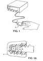
- Figure 1 shows the finger 7 of an individual placed into a clam-shell type fixture 6 wherein the optical and other physical measurements can be easily performed.
- the clam-shell type holder allows for adaptability to various finger sizes.
- other fixture methods such as Figures 1B through 1E , can be used to obtain similar physical data as using the clam-shell fixture.
- Non-invasive, transcutaneous hematocrit measurement using a spectroscopic method is described below:
- i D ⁇ ⁇ ⁇ ⁇ ⁇ .
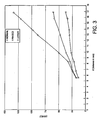
- Figure (2 ) shows the actual patient data plot of In(i) vs. d, where a is determined directly from the slope of the line.
- the attenuation coefficient, ⁇ is a bulk term which encompasses the attenuation measurement sensitivity to variations in skin color, presence of bone, callous, blood and water content, etc.
- ⁇ expresses the optical "path lengthening" effects of both the absorption and scattering characteristics of the tissue. Therefore, since ⁇ is a function of HCT and the intensity of the transmitted light can be measured, the HCT can be calculated by manipulation of the preceding relationships.
- the troublesome and complex tissue function, A can be eliminated by taking the logarithm of (9) and differentiating with respect to the distance, d.
- the term X b is not known but changes with time as a result of a patient's cardiac cycle. Therefore, by differentiating with respect to time, this parameter becomes the time rate of change of blood volume which can be obtained through several methods described below. These time and distance derivatives may be performed in either order.
- Figure 4 shows the linearity of K b (H).
- Equation (18a) indicates a small nonlinearity in H may occur based on the magnitude of K for a given individual.
- the change in received intensity with time is a result of the change in normalized blood volume resulting from the cardiac cycle itself as blood pulses through the examined tissue.
- the intensity of the received light is measured, its time rate of change can be calculated.
- the change with distance can be determined by placing multiple emitters (such as 1-4 in Figure 1 A) and/or multiple detectors such that multiple thicknesses of tissue and hence, lengths of tissue are penetrated.
- ⁇ is a function of the bulk absorption and scattering coefficients, K and S, as well as hematocrit, H .
- K and S are functions of the fractional volumes of each constituent, X b , X s , and X w , which must be used to prorate the individual absorption and scattering coefficients, K b , K s , K w , S b and S s .
- the transducer system must be responsive not only to a change in volume ( ⁇ V ) due to the influx of the blood, but must also be responsive to the normalized change in volume of blood, normalized to the total volume of the finger ( V f )or tissue being measured, ⁇ ⁇ V f V f .
- C 1 and C 2 are inter-related photon flux densities between the dermal layer 12 and the subcutaneous layer, 12a (see Figures 1C and 1E ).
- C 3 is a strong function of z 1 , z 2 , ⁇ 1 , and ⁇ 2 ; i.e., the thickness of the dermis or dermal layer 12, subcutaneous layer 12a, and their respective ⁇ 's.
- C 3 ' is a function of the inter-related photon flux densities C 1 and/or C 2 and if Xb' 1 does not equal Xb' 2 , then the slope C 3 ' will not be nulled out by the Xb' monitors mentioned. Therefore, Xb 2 ' must be greater than Xb 1 '. Then the pressure or piezo monitors will compensate correctly.
- the circular pressure balloon is ideal for not only sensing the change in a pressure, but also providing a pressure against the dermis causing Xb 1 ' to be small. However, recognizing that the penetration depth of the 800 nm light typically extends through dermal layer 12 into the deep tissue, subcutaneous layer 12a, a different wavelength selection is appropriate.
- C 3 ' will only be a function of z 1 and ⁇ 1 .
- Those selected wavelengths would be the green (570-595 nm) wavelength and 1300 nm wavelength.
- ⁇ X b / ⁇ t can be measured and compensated for through the use of a number of different methods - (a) a pressure transducer, (b) a strain transducer such as piezo electric film or strain gage, (e) a different wavelength of light, such as 1300 nm, which also holds ⁇ X b / ⁇ t information, but holds little hematocrit information, or (d) other transducers.
- a pressure transducer a strain transducer such as piezo electric film or strain gage
- a different wavelength of light such as 1300 nm
- ⁇ V f - ⁇ V sys .
- the selection of the 1300 nm wavelength is based on criteria established in U.S. Patent Number 5,372,136 .
- the approach here is not to solve for ⁇ X b / ⁇ t and substitute into (19) but to ratiometrically eliminate ⁇ X b / ⁇ t .
- the assumptions following equation (12) are no longer valid; i.e., ⁇ X s / ⁇ t and ⁇ X w / ⁇ t are not negligible, since water absorption at 1300 nm is so large.
- ⁇ X b / ⁇ t measurements such as doppler, ultrasonic, electrical conductivity, magnetic permeability and other techniques have similar derivations.
- the important consideration is that ⁇ X b / ⁇ t is a normalized time varying quantity.
- averaging can eliminate system noise whose frequency components have corresponding periods much shorter than the interval.
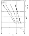
- the data acquisition rate is approximately 1000 data samples per second. This means that within a typical human pulse about 1000 samples of data are available for appropriate numerical analysis, averaging and qualification. Recognizing that both the intensity of light and the pressure in the transducer system are changing in time during the influx of blood is of great importance. Since the parametric relationship of ⁇ / ⁇ t as a function of ⁇ P/ ⁇ t (where P is pressure) during the cardiac cycle should be linear, a multiplicity of data points facilitate qualification of the signal for accuracy and linearity. Whereas, prior techniques involving only the peak and valley values of the cardiac cycle require numerous pulses to qualify the data set. See Figures 8 , 9 and 10 .
- Fig. 9 shows (di/dt)/i vs dP/dt showing that within one cardiac pulse 200 plus data samples are linearly related, i.e. trace up out of the "0" origin up to a maximum value and then back down toward the origin again.
- Fig. 10 shows d ⁇ /dt/dP/dt versus time during one single cardiac pulse with 200 plus samples of data from time 15 - 45 giving a value of about 4.5 thousandths. The data can then be averaged, as if 200+ individuals pulse (max-min) values were actually taken as present day oxymeters do.
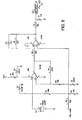
- Figure 6 shows a piezo transducer circuit having a transducer 50 connected to a series of operational amplifiers, resistors and capacitors in accordance with the figure. The circuit terminates in an analog output 52 for connection to the "E" connection shown in the middle left side of Figure 16D (corresponding to Fig. 9D in U.S. Patent Number 5,372,136 ).
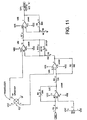
- Figure 11 shows a pressure transducer circuit having a pressure transducer made 62 connected to a series of operational amplifiers, a capacitor, resistors and variable resistors as shown in the figure. The circuit terminates in an analog output also connected to the aforementioned "E" connection.
- a crystal oscillator is connected to ground and to the non-inverting input of a first operational amplifier, which may be an LM158.
- the non-inverting input of the first operational amplifier is connected to ground by a .047 ⁇ F capacitor C3.
- the first operational amplifier's feedback path to its inverting input includes a 470 K resistor R8.
- the first operational amplifier is suitably biased at the junction of a 220 ⁇ resistor R7 and a 150 ⁇ F capacitor C4 that are connected between VCC and ground.
- a second operational amplifier which may also be an LM 158, receives the output of the first operational amplifier at its inverting input via a 10 K ⁇ resistor R5.
- the second operational amplifier's non-inverting input is connected to several locations:
- first through fourth operational amplifiers which may be LM348s, are illustrated.
- the operational amplifiers are powered and biased by voltages VCC and VEE.
- the first operational amplifier's non-inverting input is set to a value determined by the tap setting of a 1 K ⁇ adjustable resistor R2 that extends between VCC and VEE.
- the DAC input drives the first operational amplifier's inverting input via a 1 K ⁇ resistor R1.
- the first operational amplifier's feedback path includes a 50 K ⁇ adjustable resistor R4.
- the first operational amplifier drives the second operational amplifier's inverting input through an 11 K ⁇ resistor R3.
- the feedback path to the inverting input of the second operational amplifier includes a 100 ⁇ resistor R5.
- a pressure transducer 62 which may include a Motorola MPX20100P, has opposite terminals that drive the non-inverting inputs of the second and third operational amplifiers, respectively.
- the other two opposite terminals of the transducer are connected to VCC and ground, respectively.
- the second operational amplifier drives the inverting input of the third operational amplifier via a 750 ⁇ resistor R6.
- the third operational amplifier's feedback path to its inverting input includes a parallel arrangement of a 93.1 K ⁇ resistor R10 and a 001 ⁇ F capacitor C1.
- the third operational amplifier drives the non-inverting input of the fourth operational amplifier via a 1 K ⁇ resistor R7.
- the inverting input of the fourth operational amplifier is connected to ground via a 1 K ⁇ resistor R8.
- the feedback path to the inverting input of the fourth operational amplifier includes a 50 K ⁇ adjustable resistor R9.
- the fourth operational amplifier drives the output of the FIG. 11 circuit.
- Figure 1 Physical embodiments as shown in Figure 1 include the optical array, pressure transducer/balloon system and clam-shell fixture. Requisites of the preferred embodiment include a holder for the finger (or other tissue) such as seen in Figures 1 and 1A and 1B . This clam-shell fixture not only secures the tissue but also the optical array, and transducer system.
- Figure 1D is a schematic diagram for a mylar base member 38 that is shaped generally like a cross. As oriented in Figure 1D , vertically extending portion 52 crosses with a horizontally extending portion 54 to yield top leg 56, bottom leg 58, and side legs 60, 62. In use, a finger 7 lies along the longitudinally extending portion 52 with the finger tip placed on the top leg 56 to properly cover the arrangement of LED's 32 and photodetector 34, which are arranged like those on Figures 1A - 1C .
- a piezoelectric pressure transducer or strain gage 66 spans the horizontally extending portion 54 from near the tip of side leg 60 to the tip of side leg 62. In this orientation, the transducer or gage may be wrapped around the finger 7 for use in measurements.
- the optical array 30, seen in Figure 1D shows the arrangement of multiple LED's 32 spaced at known separation distances from the detector 34.
- This array provides for the instantaneous distance, or " d ", derivative, by the transmission mode shown in Figure 1A or in reflectance modes shown in Figures 1B and 1C .
- a single LED 42 swept across the finger 7 or tissue surface 9 with a stepper motor 44 would provide a d derivative as would a cantilevered clam-shell with an angular measurement device.
- d must be known and/or fixed.
- AJso the detectors and emitters may be placed anywhere about the finger.
- the pressure/balloon, strain gage, or peizo transducer system incorporated within the clam-shell fixture provides the contact surface area needed to define the ⁇ X b / ⁇ t.
- the above mentioned optical array can be utilized transmissively and/or reflectively provided the separation distance between the detector and first emitter ( d 1 ) is greater than 3mm.
- selection criteria of the preferred wavelength must include an understanding of equation (5). That is, a wavelength whose coefficients K r , K w , K p are small compared to K b and which are also insensitive to oxygen saturation status must be selected. Such wavelengths include 805 nm, 590 nm, 569 nm and other isobestic wavelengths with negligible water absorption. While non-isobestic wavelengths, with small water absorption, could function, a second wavelength would be needed to null out the oxygen saturation effects.
- a second wavelength must be chosen.
- a second wavelength, 570 nm is chosen where K p570 is less than K p805 .
- the second wavelength, 1060 nm is chosen where K p570 is much less than K p1060 .
- the first wavelength used to measure the H and the reference bilirubin, K p (bilirubin), is 570 nm
- the second wavelength, 440 nm is then chosen where K p570 is much less than K p440 .
- the selection of these above mentioned wavelengths therefore assures uniqueness for the measurement of the desired biologic constituent.
- the 8 13 ratio has both hematocrit and glucose information.
- the ⁇ 8 ⁇ ' 8 / ⁇ P (equation 18a) ratio has only hematocrit information. Therefore the differential combination of those ratios will be a strong function of glucose only.
- tissue perfusion low X b and low ⁇ X b / ⁇ t
- d dependence varying finger sizes
- tissue nonhomogeneity the tissue penetration depth for 660 nm light is not the same as for 940 nm light
- H dependence the tissue penetration depth for 660 nm light is not the same as for 940 nm light
- Equation (13) indicates an "offset term", - 1 A ⁇ ⁇ A ⁇ X b .
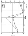
- the bulk attenuation coefficient, ⁇ can be easily measured with the optical array, at 805 nm, utilizing equation (10) and as described in Section IV(C). Notice that at 805 nm, a is a strong function of H and X b since K s8 K w8 , K p8 are small, see Figure 12 .
- X b itself can be determined using a strain gage in the following two step approach.
- Step One measure the strain gage resistance when the finger is made bloodless, by squeezing finger, such as with a stepper motor.
- Step Two measure the strain gage resistance when the finger is blood filled, for example by suction.
- strain gage resistances are proportional to the radius, r and R, of the finger.
- FIGS. 15A-15C detail the electronics of one circuit suitable for use within the scope of the present invention.
- the memory and computation means ( FIGS. 15A-15C ) are connected via a "bus" structure between PROMS (U110, U111), microprocessor MC68HC000 (U106), static RAMS (U112, U113), and isolation buffers to the low-level analog circuitry ( FIG. 14 ).
- a crystal controlled oscillator circuit (U101A,B) is divided by 2 to provides a symmetric master clock to the microprocessor; this clock is further subdivided and used to provide clocking for the analog-to-digital converter (U208) and timer (U109).
- Strobe lines are generated through a decoder arrangement to drive each of the subsystems of the device and also control the isolation bus buffers (U201,U202).
- Timer outputs are fed back into the microprocessor and encoded (U104) to produce interrupts at specific intervals for system functions.
- One timer is shared by subsystems which control the liquid crystal display means, the keyboard entry means, the audible indicator, and the cycling background system self-test.
- Another timer is dedicated exclusively to provide a high priority interrupt to the microprocessor; this interrupt drives software which controls the basic sensor sampling mechanism.
- An expansion connector (J101) is included to allow extended testing of the device or connection to external data-logging equipment such as a printer or computer interface.
- the local bus isolates the sensitive analog circuitry from the main digital circuitry. This prevents spurious crosstalk from digital signals into the analog circuitry and thereby reduces superimposed noise on the measured signals. It is on this local bus that the Digital-to-Analog Converters (DAC) and Analog-to-Digital Converters (ADC) transmit and receive digital information while processing the low-level analog signals.
- DAC Digital-to-Analog Converters
- ADC Analog-to-Digital Converters
- the Low Level Sensor electronic section combines subsystems to both measure and modulate the current produced from each optical sensor. Since the pulsatile component of the optical energy transmitted through or reflected off of tissue comprises only a small part of the overall optical energy incident on the sensor, means are provided to "null out” in a carefully controlled and accurately known way the non-pulsatile component of the light-produced current in the sensing detector. The remaining signal can then be dc-amplified and filtered in a straightforward manner and presented to the ADC (U208) for conversion into a digital value representative of the relative AC pulsatile component.
- ADC U208
- the DC component can easily be calculated as a function of the sensing means' sensitivities and the electronic stages' gains.
- the functions determining these AC and DC values can (if necessary) be trimmed in software by calibration constants which are stored in EEPROM (U307) and retrieved each time the unit is powered on.
- the current which modulates the optical sources is also controlled (U203) and precisely adjusted (U306) to optimize signal reception and detection.
- the modulation current can be adjusted on a pulse-by-pulse basis to minimize noise-induced inaccuracies.
- background noise such as 60 Hz
- Interrupt-driven software algorithms acquire the sensor data, provide a real-time pulse wave contour, and determine pulse boundaries. Completed buffers (i.e. one entire pulse per buffer) of sensor data are then passed to the foreground software processes for computation. This involves the determination of the background-compensated AC pulsatile and DC static values of intensities for each wavelength. Through averaging and selective elimination of abnormal values, results are then calculated and displayed on the LCD. The modulating and nulling currents are (if necessary) also adjusted to utilize the electronic hardware efficiently and optimally.
Abstract
Description
- The present invention relates to improvements in the systems and methods for non-invasively measuring one or more biologic constituent concentration values. More particularly, the present invention relates to non-invasive spectrophotometric systems and methods for quantitatively and continuously monitoring the hematocrit and other blood parameters.
- Modem medical practice utilizes a number of procedures and indicators to assess a patient's condition. One of these indicators is the patient's hematocrit. Hematocrit (often abbreviated as HCT) is the volume expressed as a percentage of the patient's blood which is occupied by red corpuscles, commonly referred to as red blood cells. The present invention is presented in the context of hematocrit. However, it is to be understood that the teachings of the present invention apply to any desired biologic constituent parameter.
- Medical professionals routinely desire to know the hematocrit of a patient. In order to determine hematocrit using any of the techniques available to date, it is necessary to draw a sample of blood by puncturing a vein or invading a capillary. Then, using widely accepted techniques, the sample of blood is subjected to either high-speed centrifuge, cell counting, ultrasonic, conductometric or photometric methods of evaluating the sample of blood in a fixed container. Prior
U.S. Patent Number 5,372,136 indicates a system and methodology for determining the hematocrit non-invasively, without puncturing or invading the body, spectrophotometrically and continuously in a subject. The present invention relates to improvements upon the above cited system. US 5, 499, 627 is also mentioned as further background. - Beyond the above referenced patent, others have suggested various means of noninvasive measurement of hematocrit. Specifically,
Mendelson, U.S. Patent Number 5,277,181 ;Seeker, U.S. Patent 5,188,108 ;Gonatas, U.S. Patent Number 5,528,365 ;Ishikawa, U.S. Patent Number 5,522,388 ;Shiga, U.S. Patent Number 4,927,264 ;Tsuchiya, U.S. Patent Numbers 5,441,054 ,5,529,065 ,5,517,987 and5,477,051 ; andChance, U.S. Patent Numbers 5,353,799 ,5,402,778 , and5,673,701 have attempted to define means of directly measuring desired biologic constituents such as hematocrit. Even though the various patents indicate the need to utilize multiple wavelengths measured at different detection sites and/or the need to perform differential or ratiometric operations on the detected optical signal, all fail to isolate and resolve the individual and specific scattering and absorption coefficients of the desired constituent. At best they address only bulk attenuation coefficients and/or bulk diffusion constants of the scattering media while attempting to resolve such constraints as tissue nonhomogeneity. As an example, tissue may be considered to contain a bulk absorptive coefficient due to blood, collagen, water, fibers, bone, fingernail, etc. Hence, in order to determine the absorptive coefficient of the blood itself, the bulk value of the tissue per se must be prorated by the amounts of the above constituents. Secondly, the actual absorptive coefficient of the blood must then be decoupled or isolated from its proration factor as well. - Thus, it is an object of the present invention to provide an improvement in the systems and methods for the non-invasive (transcutaneous) and continuous determination of the blood Hematocrit in living tissue.
- It is yet another object of the present invention to provide an improvement in the systems and methods for the non-invasive (transcutaneous) and continuous determination of the blood constituents, including glucose, bilirubin, cholesterol, tissue water, etc. in living tissue.
- It is another object of the present invention to provide a system and method and apparatus for the display of both immediate and/or continuous visual information regarding the HCT of the subject.
- It is yet another object of the present invention to provide a repeatable and reliable method and apparatus for the non-invasive determination of hematocrit transcutaneously and in real time even under varying physiological conditions.
- Still another object of the present invention is to provide a method and apparatus for the instantaneous determination of the bulk absorption coefficient of the scattering media.
- These and other objects and advantages of the invention will become more fully apparent from the description in the specification and claims, which follow.
- In one aspect, the present invention as defined in the appended claims accomplishes the transcutaneous, noninvasive, real-time and continuous measurement of the hematocrit and other blood constituents of the patient.
- The invention may be implemented by providing electronic circuitry to receive signals from a detector and to generate appropriate signals at various input sites in the known circuitry as described in
U.S. Patent Number 5,372,136 . Yet another aspect of the present invention is the ability to extract the blood absorption coefficient from the bulk tissue diffusion constant or the bulk absorption coefficient of the scattering media by requiring both physical and mathematical operations. -
-
Figures 1 and 1A show a finger placed into a clam-shell type fixture constituting a receiving means for detector and emitter arrays operating in a transmission mode and the blood conduit which in the figures is the finger. -
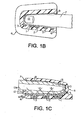
Figures 1B and 1C are similar toFigure 1A , but show the detector and emitter arrays operating in a reflectance mode. -
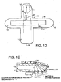
Figure 1D is a schematic diagram for a mylar base with a detector, emitters and either a strain gage or a pressure transducer for inclusion in the clam-shell fixture. -
Figure 1E is a schematic diagram for a detector emitter array using a single, moveable emitter in a transmission mode. -
Figure 2 shows actual patient data plot ofIn(i) vs. d. -
Figure 3 illustrates actual patient data of the (∂i/∂t)/i dependence on d. -
Figure 4 shows the blood absorption coefficient's dependence on hematocrit. -
Figure 5 indicates the nonlinear relationship between the Vc /Vf and pressure. -
Figure 6 shows the electrical circuit diagram of the piezo film / strain gage transducer means. -
Figure 7 is the plot of f(H) vs. measured Hematocrit. -
Figure 8 shows the instantaneous time derivatives of (∂i/∂t)/i and ∂ P/∂t versus time during one cardiac pulse. -
Figure 9 plots (∂il∂t)li versus ∂ P/∂t for a given human pulse at d1, d2, d3, and d4. -
Figure 10 plots (∂i/∂t)/(∂P/∂t) versus time during a single cardiac pulse cycle. -
Figure 11 is the circuit diagram of the pressure transducer means. -
Figure 12 plots α versus Xb at a fixed Hematocrit. -
Figure 13 gives the patient data of the new transcutaneous Hematocrit method and system plotted versus the measured Hematocrit standard. -
Figures 14 ,15A - 15C ,16A -16D and17A - 17D correspond tofigures 7 ,8A - 8C ,9A-9D and10A - 10D ofUS 5, 372, 136 and are described in an appendix in this description for completeness. - In a preferred embodiment of the invention, measurements are conducted using a modified version of the apparatus described in
U.S. Patent Numbers 5,456,253 and5,372,136 , corresponding toEP-A-0693900 . - Thus, in a preferred embodiment, hematocrit is measured in living tissue located at some convenient location on the body, such as, an ear lobe, finger tip, nose or other accessible tissue sites. In a preferred embodiment the apparatus and signal manipulations described in
U.S. Patent Number 5,372,136 are utilized to measure various optical parameters that will be described hereafter. The numbered components inFigures 1, 1A ,1B, and 1C are similar to the numbers inFigure 1 ofU.S. Patent Number 5,456,253 . - In the present disclosure,
Figure 1 shows thefinger 7 of an individual placed into a clam-shell type fixture 6 wherein the optical and other physical measurements can be easily performed. The clam-shell type holder allows for adaptability to various finger sizes. However, other fixture methods such asFigures 1B through 1E , can be used to obtain similar physical data as using the clam-shell fixture. - Non-invasive, transcutaneous hematocrit measurement using a spectroscopic method is described below:
- Earlier spectrophotometric techniques have fallen short of being able to fully characterize the individual blood absorbance coefficients. The following discussion demonstrates the method of decoupling, or isolating from the bulk tissue attenuation parameters (including the convoluted absorptive and scattering parameters) the individual blood absorptive constants. This unique method identifies, isolates and compartmentalizes each of the contributing biologic elements of the tissue media. This decoupling process can either isolate the blood absorbance of interest and/or eliminate the scattering contribution from the bulk media measurement.
- From photon diffusion analysis:

where,


and where, - α
- = Bulk attenuation coefficient of the tissue sample
- K
- = Bulk absorption coefficient of the tissue sample
- S
- = Bulk scattering coefficient of the tissue sample
- D
- = Diffusion constant
- Kb
- = Macroscopic absorption coefficient for whole blood (WB)
- Sb
- = Macroscopic transport - corrected scattering coefficient for WB
- Kp
- = Macroscopic absorption coefficient for plasma
- Ks
- = Macroscopic absorption coefficient for skin, & other non water/blood components
- Kw
- = Macroscopic absorption coefficient for water
- V
- = Volume of a red blood cell (RBC)
- H
- = Hematocrit, volume fraction of RBCs to total blood volume
- SAT
- = Oxygen saturation %
- σ ao
- = Absorption cross - section of oxygenated RBCs
- σ ar
- = Absorption cross - section of deoxygenated RBCs
- σ s
- = Transport - corrected scattering cross-section of RBCs
- Xb
- = Fractional volume of blood per total tissue volume
- Xs
- = Fractional volume of skin, & non water/blood components per total tissue volume
- Xw
- = Fractional volume of water per total tissue volume
- Ψ(ρ)
- = The photon density at a distance ρ
- S(ρ)
- = The source function.
- The light flux, or intensity, i, is given by


where A is a nontrivial function of the tissue scattering coefficient, S, the distance, d (if small), and the bulk attenuation coefficient, α. If α d >> 1, then (8) becomes:
where
where n is the power that d is raised to. -
Figure (2 ) shows the actual patient data plot of In(i) vs. d, where a is determined directly from the slope of the line. - The attenuation coefficient, α, is a bulk term which encompasses the attenuation measurement sensitivity to variations in skin color, presence of bone, callous, blood and water content, etc. In addition, α expresses the optical "path lengthening" effects of both the absorption and scattering characteristics of the tissue. Therefore, since α is a function of HCT and the intensity of the transmitted light can be measured, the HCT can be calculated by manipulation of the preceding relationships.
- Beginning with equation (9), the troublesome and complex tissue function, A, can be eliminated by taking the logarithm of (9) and differentiating with respect to the distance, d. Unfortunately the term Xb is not known but changes with time as a result of a patient's cardiac cycle. Therefore, by differentiating with respect to time, this parameter becomes the time rate of change of blood volume which can be obtained through several methods described below. These time and distance derivatives may be performed in either order.
- [1] Taking the logarithm of (9) and differentiating with respect to the distance, d, yields:

Next the derivative of(10) with respect to time, t, gives:
- [2] Alternatively, first differentiate (9) with respect to time, t, to get:

When


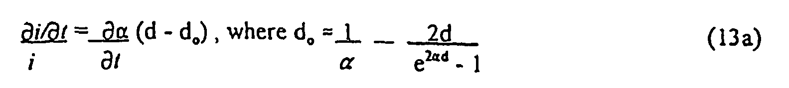
-
Figure 3 plainly demonstrates the offset term when the various graph lines are extrapolated to d = 0. The amount of offset is shown along the y-axis. - Next differentiate (13) with respect to distance, d, to eliminate that offset term to get:

- Equations (3) - (7) are now used to extract the hematocrit from α. Squaring (3) and differentiating with respect to time results in:
- Substituting the derivatives of (4) and (6) into (15) and rearranging:

At S05 nm.

- By using the 805 nm wavelength the red blood cell absorption cross-section constants are equal, σoo = σlr, and Kp is negligible. The hematocrit can then be determined directly from Kb as (5) simplifies to:

-
Figure 4 shows the linearity of Kb(H). - If KbS >> KSb, where S is approximately 1.0 / mm in human tissue, then solving (17) for Kb and substituting into (17a) gives:

- To rewrite in terms of measurable intensity, i, (10) and (14) are substituted into (18) to obtain:

- If KbS is not >> KSb, then substituting (5) and (7) into (17a) and rearranging terms yields:


- Equation (18a) indicates a small nonlinearity in H may occur based on the magnitude of K for a given individual.
- It should be reiterated that the change in received intensity with time is a result of the change in normalized blood volume resulting from the cardiac cycle itself as blood pulses through the examined tissue. As the intensity of the received light is measured, its time rate of change can be calculated. The change with distance can be determined by placing multiple emitters (such as 1-4 in
Figure 1 A) and/or multiple detectors such that multiple thicknesses of tissue and hence, lengths of tissue are penetrated. - To examine

- Vb = Volume of blood,
- Vw = Volume of water, and
- Vs = Volume of skin, tissue and other non-water or blood components.
- By definition,

differentiating (20) with respect to time gives:
- Since


- It is emphasized that α is a function of the bulk absorption and scattering coefficients, K and S, as well as hematocrit, H. Further, that K and S are functions of the fractional volumes of each constituent, Xb, Xs, and Xw, which must be used to prorate the individual absorption and scattering coefficients, Kb, Ks, Kw, Sb and Ss. Therefore, the transducer system must be responsive not only to a change in volume (ΔV) due to the influx of the blood, but must also be responsive to the normalized change in volume of blood, normalized to the total volume of the finger (Vf )or tissue being measured,

- For Reflectance (R) measurements in homogenous tissue:

where r is the radial distance, and
- However, for tissue, which is typically non-homogeneous with a dermal and subcutaneous layer, the reflectance will not be a trivial function but can be described as approximately:

- Where C1 and C2 are inter-related photon flux densities between the
dermal layer 12 and the subcutaneous layer, 12a (seeFigures 1C and1E ). Likewise, C3 is a strong function of z1, z2, α1, and α2; i.e., the thickness of the dermis ordermal layer 12, subcutaneous layer 12a, and their respective α's. - Since C3' is a function of the inter-related photon flux densities C1 and/or C2 and if Xb'1 does not equal Xb'2, then the slope C3' will not be nulled out by the Xb' monitors mentioned. Therefore, Xb2' must be greater than Xb1'. Then the pressure or piezo monitors will compensate correctly. The circular pressure balloon is ideal for not only sensing the change in a pressure, but also providing a pressure against the dermis causing Xb1' to be small. However, recognizing that the penetration depth of the 800 nm light typically extends through
dermal layer 12 into the deep tissue, subcutaneous layer 12a, a different wavelength selection is appropriate. Thusly, when the photons only penetrate into thedermal layer 12, C3' will only be a function of z1 and α1. Those selected wavelengths, as mentioned inU.S. Patent No. 5,372,136 , would be the green (570-595 nm) wavelength and 1300 nm wavelength. The green wavelengths are used as the hematocrit bearing wavelength and the 1300 nm wavelength is used as the non-hematocrit bearing, or reference wavelength. That is, for reflectance measurements the green (Gr)-1300 wavelength pair would give the hematocrit information as:
III. Methods of
- ∂Xb /∂t can be measured and compensated for through the use of a number of different methods - (a) a pressure transducer, (b) a strain transducer such as piezo electric film or strain gage, (e) a different wavelength of light, such as 1300 nm, which also holds ∂Xb /∂t information, but holds little hematocrit information, or (d) other transducers. The individual methods of obtaining ∂Xb /∂t are addressed below.
A. Pressure Transducer Measurement of
- Consider a
pressure transducer system 36 with a gas filledbladder 38 surrounding afinger tip 10 of a patient contained within a fixed volumeclam shell fixture 6, seeFigures 1 , 1A- 1D. The same derivations, equations, and results would apply to any other body appendage or tissue that could be contacted such that a change in the tissue volume would change the pressure of the contacted pressure transducer system. For a finger note:
where
Vclom = Clam-shell fixture volume
Vsys = Bladder system volume
Vf = Finger volume - Also ΔVf = -ΔVsys. The system will have a bulk modulus of elasticity, β, such that:

- Substituting (23) into (24) results in:

- Since Δ Vf = Δ Vb then from (25) we have:

- As stated above, β is a constant of the pressure transducer system. However, an empirical solution for


Figure 5
B. Strain Transducer (Strain Gage/Piezo Electric Film) Measurement of
- Again it is assumed that ΔVb = ΔVf, and that the finger changes volume only by a change in diameter. A strain gage or piezo electric film is secured tightly around the finger (again any applicable body appendage or tissue would apply) such that a change in diameter would produce a strain in the transducer. Specifically assuming a cylindrical finger:

- Normalizing with respect to Vf, yields:

- A change in the length of the transducer element is related to a change in finger radius by ΔL = 2πΔr, therefore:

where
Figure 6 , as it is proportional to the rate of change in the gage resistance. - For a piezo electric film the voltage produced is proportional to the strain, therefore:

where, g31 is the piezoelectric coefficient for the stretch axis, τ is the film thickness and ν(t) is the open-circuit output voltage.
C. 1300 nm Light Measurement of
- The selection of the 1300 nm wavelength is based on criteria established in
U.S. Patent Number 5,372,136 . The approach here is not to solve for ∂Xb /∂ t and substitute into (19) but to ratiometrically eliminate ∂Xb /∂t. In the case of the 1300 nm reference wavelength, the assumptions following equation (12) are no longer valid; i.e., ∂Xs /∂t and ∂Xw /∂t are not negligible, since water absorption at 1300 nm is so large. Hence, for the 1300 nm equations (13), (14) and (15) would result in:
where, α, and the bulk and material specific K, and S are wavelength (λ) dependent. Recalling that, Xb + Xs + Xw = 1, by definition, and that:
- By substituting (31) into (30) and noting that Kw13 = Kb13, the following is obtained:

- Since,


- Therefore, to eliminate


- Since S 8 and K 13 are well behaved and known (let K13 /S8 = G) in human tissue and the ratio


- Where

Figure 7 for f(H). - If hematocrit is constant over a given time interval, averaging can eliminate system noise whose frequency components have corresponding periods much shorter than the interval. In addition, by observing the data variance during the interval it may be determined that the data is invalid. In the present system, the data acquisition rate is approximately 1000 data samples per second. This means that within a typical human pulse about 1000 samples of data are available for appropriate numerical analysis, averaging and qualification. Recognizing that both the intensity of light and the pressure in the transducer system are changing in time during the influx of blood is of great importance. Since the parametric relationship of ∂α/∂t as a function of ∂P/∂t (where P is pressure) during the cardiac cycle should be linear, a multiplicity of data points facilitate qualification of the signal for accuracy and linearity. Whereas, prior techniques involving only the peak and valley values of the cardiac cycle require numerous pulses to qualify the data set. See
Figures 8 ,9 and10 . -
Fig. 8 shows di/dt/i as well as dP/dt verses time during the cardiac pulse - it is a pulse showing = 200+ data samples during the pulse. -
Fig. 9 shows (di/dt)/i vs dP/dt showing that within one cardiac pulse 200 plus data samples are linearly related, i.e. trace up out of the "0" origin up to a maximum value and then back down toward the origin again. -
Fig. 10 shows dα/dt/dP/dt versus time during one single cardiac pulse with 200 plus samples of data from time 15 - 45 giving a value of about 4.5 thousandths. The data can then be averaged, as if 200+ individuals pulse (max-min) values were actually taken as present day oxymeters do. - Since the above derivations are based on the assumption of tissue homogeneity (i.e.,∂Xb1 /∂t = ∂Xb2 /∂t , A 1 = A2, ∂A1/∂Xb = ∂A2/∂Xb, α1 = α2, etc.), high-speed, single-pulse, multiple parameter sampling allows for mathematical qualification of homogeneity, by requiring linearity of In(i) vs. d and (∂i/∂t)/i vs. d Under these constraints and when qualified as homogeneous, (∂α/∂t)/(∂P/∂t) also may be assumed to be linear over the entire pulse contour. Finally, both α and ∂α/∂t must also be linear, further assuring homogeneity in Xb , and in ∂Xb /∂t.
- See the Appendix here to for the operational circuitry description, taken from
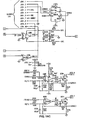
US 5,372,136 , which allows for high speed sampling of the optical intensities.Figures 6 and11 show additional circuitry for sampling of pressure, peizo, and strain-gage measurements. - The circuitry shown in
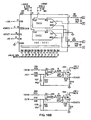
Figures 14 to 17 and discussed in the Appendix is programmable by conventional techniques to solve and implement the equations and calculations presented in this application.Figure 6 shows a piezo transducer circuit having atransducer 50 connected to a series of operational amplifiers, resistors and capacitors in accordance with the figure. The circuit terminates in ananalog output 52 for connection to the "E" connection shown in the middle left side ofFigure 16D (corresponding toFig. 9D inU.S. Patent Number 5,372,136 ).Figure 11 , on the other hand, shows a pressure transducer circuit having a pressure transducer made 62 connected to a series of operational amplifiers, a capacitor, resistors and variable resistors as shown in the figure. The circuit terminates in an analog output also connected to the aforementioned "E" connection. - Referring more specifically to
FIG. 6 , a crystal oscillator is connected to ground and to the non-inverting input of a first operational amplifier, which may be an LM158. The non-inverting input of the first operational amplifier is connected to ground by a .047 µF capacitor C3. The first operational amplifier's feedback path to its inverting input includes a 470 K resistor R8. The first operational amplifier is suitably biased at the junction of a 220 Ω resistor R7 and a 150 µF capacitor C4 that are connected between VCC and ground. - A second operational amplifier, which may also be an LM 158, receives the output of the first operational amplifier at its inverting input via a 10 KΩ resistor R5. The second operational amplifier's non-inverting input is connected to several locations:
- to a voltage VB51, which may be 4.096 volts, through a 10 KΩ resistor R2;
- to a middle node of a voltage divider, the voltages divider extending between the non-inverting input of the first operational amplifier via a 10 MΩ resistor R4 to the middle node, and via a 10 KΩ resistor R1 to ground;
- to the inverting input of the first operational amplifier via a 10 KΩ resistor R9; and
- to ground via a 220 µF capacitor C5.
- Of course, the particular choice, arrangement and values of components shown in
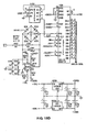
FIG. 6 may be varied while still remaining within the scope of the invention. - Referring now to
FIG. 11 , first through fourth operational amplifiers, which may be LM348s, are illustrated. The operational amplifiers are powered and biased by voltages VCC and VEE. - The first operational amplifier's non-inverting input is set to a value determined by the tap setting of a 1 KΩ adjustable resistor R2 that extends between VCC and VEE. The DAC input drives the first operational amplifier's inverting input via a 1 KΩ resistor R1. The first operational amplifier's feedback path includes a 50 KΩ adjustable resistor R4. The first operational amplifier drives the second operational amplifier's inverting input through an 11 KΩ resistor R3. The feedback path to the inverting input of the second operational amplifier includes a 100 Ω resistor R5.
- A
pressure transducer 62, which may include a Motorola MPX20100P, has opposite terminals that drive the non-inverting inputs of the second and third operational amplifiers, respectively. The other two opposite terminals of the transducer are connected to VCC and ground, respectively. - The second operational amplifier drives the inverting input of the third operational amplifier via a 750 Ω resistor R6. The third operational amplifier's feedback path to its inverting input includes a parallel arrangement of a 93.1 KΩ resistor R10 and a 001 µF capacitor C1.
- The third operational amplifier drives the non-inverting input of the fourth operational amplifier via a 1 KΩ resistor R7. The inverting input of the fourth operational amplifier is connected to ground via a 1 KΩ resistor R8. The feedback path to the inverting input of the fourth operational amplifier includes a 50 KΩ adjustable resistor R9. The fourth operational amplifier drives the output of the
FIG. 11 circuit. - Of course, the particular choice, arrangement and values of components shown in
FIG. 11 may be varied while still remaining within the scope of the invention. - Physical embodiments as shown in
Figure 1 include the optical array, pressure transducer/balloon system and clam-shell fixture. Requisites of the preferred embodiment include a holder for the finger (or other tissue) such as seen inFigures 1 and 1A and 1B . This clam-shell fixture not only secures the tissue but also the optical array, and transducer system. -
Figure 1D is a schematic diagram for amylar base member 38 that is shaped generally like a cross. As oriented inFigure 1D , vertically extendingportion 52 crosses with a horizontally extendingportion 54 to yieldtop leg 56,bottom leg 58, andside legs finger 7 lies along thelongitudinally extending portion 52 with the finger tip placed on thetop leg 56 to properly cover the arrangement of LED's 32 andphotodetector 34, which are arranged like those onFigures 1A - 1C . A piezoelectric pressure transducer or strain gage 66 spans the horizontally extendingportion 54 from near the tip ofside leg 60 to the tip ofside leg 62. In this orientation, the transducer or gage may be wrapped around thefinger 7 for use in measurements. - The
optical array 30, seen inFigure 1D , shows the arrangement of multiple LED's 32 spaced at known separation distances from thedetector 34. This array provides for the instantaneous distance, or "d", derivative, by the transmission mode shown inFigure 1A or in reflectance modes shown inFigures 1B and 1C . However, as shown inFigure 1E , asingle LED 42 swept across thefinger 7 ortissue surface 9 with astepper motor 44 would provide a d derivative as would a cantilevered clam-shell with an angular measurement device. In any case, d must be known and/or fixed. AJso the detectors and emitters may be placed anywhere about the finger. - The pressure/balloon, strain gage, or peizo transducer system incorporated within the clam-shell fixture ( see Section III, A, B, C and
Figure 1A ) provides the contact surface area needed to define the ∂Xb /∂t. - High-speed sampling provides for a closer approximation of the instantaneous time, t, derivative, ∂/∂t, as opposed to peak-valley values, see
Figure 8 . Therefore, the above embodiments allow for the direct measurement of In (i) at db d2, d3 and d4 cotemporaneously, thereby determining the actual α of the sampled tissue. Likewise (∂i/∂t)/i can be directly measured at d1, d2,, d3 and d4. cotemporaneously during the pulse which determines the instantaneous ∂α/∂t. - The above mentioned optical array can be utilized transmissively and/or reflectively provided the separation distance between the detector and first emitter (d1 ) is greater than 3mm.
- Since hematocrit is an example of the desired biological constituent concentration value of interest, selection criteria of the preferred wavelength must include an understanding of equation (5). That is, a wavelength whose coefficients Kr, Kw, Kp are small compared to Kb and which are also insensitive to oxygen saturation status must be selected. Such wavelengths include 805 nm, 590 nm, 569 nm and other isobestic wavelengths with negligible water absorption. While non-isobestic wavelengths, with small water absorption, could function, a second wavelength would be needed to null out the oxygen saturation effects.
- If the desired biologic constituent value of interest is the blood glucose, bilirubin, cholesterol or other parameters, then a second wavelength must be chosen. The first wavelength, 805 nm, is used to measure the hematocrit, H, after which a Kp805 (the absorbance of plasma at λ = 805 nm) can be determined. Then, knowing the H, a second wavelength, 570 nm, is chosen where Kp570 is less than Kp805. Similarly, if the first wavelength used to measure the H and the reference glucose, Kp (glucose) is 570 nm, the second wavelength, 1060 nm, is chosen where Kp570 is much less than Kp1060. In the case of bilirubin, the first wavelength used to measure the H and the reference bilirubin, Kp (bilirubin), is 570 nm, the second wavelength, 440 nm, is then chosen where Kp570 is much less than Kp440. The selection of these above mentioned wavelengths therefore assures uniqueness for the measurement of the desired biologic constituent.
- Additionally for glucose determination, recall that the 1300 nm wavelength is not hematocrit or hemoglobin dependent but will be glucose sensitive. This is primarily due to the dependence of the scattering coefficient on the difference between the index of refraction of pure water and glucose, i.e.: recall


where η'8 = index of refraction of the RBC hemoglobin at 800 nm relative to plasma η0 (the plasma index of refraction), and,

η'13 = the index of refraction of glucose at 1300 nm relative to η0.
Therefore, the 8 13 ratio has both hematocrit and glucose information. Whereas the α8·α'8/ΔP (equation 18a) ratio has only hematocrit information. Therefore the differential combination of those ratios will be a strong function of glucose only. - The accuracy of present day pulse oximeters suffers from 4 major problems: tissue perfusion (low Xb and low ∂Xb /∂t), d dependence (varying finger sizes), tissue nonhomogeneity ( the tissue penetration depth for 660 nm light is not the same as for 940 nm light), and H dependence (see equation (5)).
- All of the above mentioned deficiencies in pulse oximetry can be eliminated by understanding equation (13). Equation (13) indicates an "offset term",

- Hence, while merely dividing (Δi/i)λ1 by (Δi/i)λ2 mitigates the effect of ∂Xb /∂t, the d's do not completely cancel, thereby yielding the above mentioned problems. To improve pulse oximeter accuracy, a derivative is needed as in (14), which eliminates the "offset term". Hence, the ratio of (∂α/∂t)805/(∂α/tt)660 results in no H. d, or Xb dependence and the use of the multiple LED array and high-speed sampling as mentioned in section IV qualifies the tissue as homogeneous.
- The bulk attenuation coefficient, α, can be easily measured with the optical array, at 805 nm, utilizing equation (10) and as described in Section IV(C). Notice that at 805 nm, a is a strong function of H and Xb since Ks8 Kw8 , Kp8 are small, see
Figure 12 . - Therefore, by knowing Xb itself, H can be determined. Xb itself can be determined using a strain gage in the following two step approach. Step One, measure the strain gage resistance when the finger is made bloodless, by squeezing finger, such as with a stepper motor. Step Two, measure the strain gage resistance when the finger is blood filled, for example by suction. Mathematically, at 805 nm and when Ks, Kp, Kw, are small, equation (3) is approximated by:

or
- Substituting (5) and (7) into (37) yields:

- With Xb and α measured and known, and with the σ's and Ss, Xs approximately constant, H can be solved with a quadratic formula or a polynomial fit.
The strain gage determination of Xb is as follows:
Let Vo = the volume of a bloodless finger. Let Vf = the volume of blood filled finger, and again considering the finger as a cylinder:

and
- From equation (20)

- Substituting (41) into (42):

- Where the strain gage resistances are proportional to the radius, r and R, of the finger.
- Choosing the wavelength of 1300 nm, where Ks and Kw are significant, the tissue water content, Xw, can be determined. Recall that 1 - Xb - Xw = Xs and substituting into (3) yields:

With α' 13,, Xb and H determined and because Kb, Ks, Kw, Sb, and Ss are known coefficient values at 1300 nm, Xw is solved with either a quadratic formula or a polynomial fit. -
Figure 13 demonstrates preliminary results with 30 patients the application of the method and apparatus and the application ofEquation 19 on numerous patients with a correlation of r = 0.96. - As implied throughout, those skilled in the art will also appreciate that the methods for determining blood hematocrit values within the scope of the present invention may be adapted for determining other non-hematocrit biologic constituent values such as glucose, bilirubin, cholesterol, tissue water, etc.
- The present invention may be embodied in other specific forms without departing from its essential characteristics. While the foregoing described embodiments are to be considered in all respects only as illustrative of the claimed invention, they are not intended to restrict the scope of the claims. The scope of the invention is, therefore, indicated by the following appended claims rather than by the foregoing description. All changes within the meaning and range of equivalency of the claims are to be embraced within their scope.
-
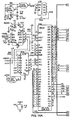
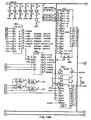
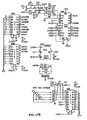
Figures 14 ,15A-15C ,16A-16D , and17A-17B detail the electronics of one circuit suitable for use within the scope of the present invention. The memory and computation means (FIGS. 15A-15C ) are connected via a "bus" structure between PROMS (U110, U111), microprocessor MC68HC000 (U106), static RAMS (U112, U113), and isolation buffers to the low-level analog circuitry (FIG. 14 ). A crystal controlled oscillator circuit (U101A,B) is divided by 2 to provides a symmetric master clock to the microprocessor; this clock is further subdivided and used to provide clocking for the analog-to-digital converter (U208) and timer (U109). Strobe lines are generated through a decoder arrangement to drive each of the subsystems of the device and also control the isolation bus buffers (U201,U202). - Timer outputs are fed back into the microprocessor and encoded (U104) to produce interrupts at specific intervals for system functions. One timer is shared by subsystems which control the liquid crystal display means, the keyboard entry means, the audible indicator, and the cycling background system self-test. Another timer is dedicated exclusively to provide a high priority interrupt to the microprocessor; this interrupt drives software which controls the basic sensor sampling mechanism. An expansion connector (J101) is included to allow extended testing of the device or connection to external data-logging equipment such as a printer or computer interface.
- The local bus isolates the sensitive analog circuitry from the main digital circuitry. This prevents spurious crosstalk from digital signals into the analog circuitry and thereby reduces superimposed noise on the measured signals. It is on this local bus that the Digital-to-Analog Converters (DAC) and Analog-to-Digital Converters (ADC) transmit and receive digital information while processing the low-level analog signals.
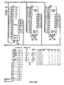
- The Low Level Sensor electronic section,
FIG. 14 , combines subsystems to both measure and modulate the current produced from each optical sensor. Since the pulsatile component of the optical energy transmitted through or reflected off of tissue comprises only a small part of the overall optical energy incident on the sensor, means are provided to "null out" in a carefully controlled and accurately known way the non-pulsatile component of the light-produced current in the sensing detector. The remaining signal can then be dc-amplified and filtered in a straightforward manner and presented to the ADC (U208) for conversion into a digital value representative of the relative AC pulsatile component. Furthermore, because the relationship between the nulling current and the average value of this AC component is known, the DC component can easily be calculated as a function of the sensing means' sensitivities and the electronic stages' gains. The functions determining these AC and DC values can (if necessary) be trimmed in software by calibration constants which are stored in EEPROM (U307) and retrieved each time the unit is powered on. - The current which modulates the optical sources (LEDs or Laser Diodes) is also controlled (U203) and precisely adjusted (U306) to optimize signal reception and detection. Through software control, the modulation current can be adjusted on a pulse-by-pulse basis to minimize noise-induced inaccuracies. Furthermore, by sampling the sensors with the modulation sources disabled appropriately, background noise (such as 60 Hz) can be rejected digitally as common-mode noise. Thus, by controlling the optical source energy and modulating the nulling current in the photosensor circuitry, it is possible to effectively cancel the effects of ambient radiation levels and accurately measure both the static (DC) and time-varying (AC) components of transmitted or reflected light.
- Interrupt-driven software algorithms acquire the sensor data, provide a real-time pulse wave contour, and determine pulse boundaries. Completed buffers (i.e. one entire pulse per buffer) of sensor data are then passed to the foreground software processes for computation. This involves the determination of the background-compensated AC pulsatile and DC static values of intensities for each wavelength. Through averaging and selective elimination of abnormal values, results are then calculated and displayed on the LCD. The modulating and nulling currents are (if necessary) also adjusted to utilize the electronic hardware efficiently and optimally.
Claims (42)
- A method for determining a desired biologic constituent concentration of the blood of a patient, the blood flowing in a pulsatile fashion in a body part of the patient so as to be subjectable to transcutaneous examination in the body part, the body part defining a blood conduit and the method comprising the steps of:(a) placing the blood conduit within a blood conduit receiver with the blood flowing in the blood conduit;(b) directing radiation into the flowing blood within the blood conduit using a radiation generator situated within said blood conduit receiver, said radiation defining a directed radiation comprising at least a first quantity of radiation at a first radiation wavelength which, when directed into the flowing blood within the blood conduit, has at least two attenuation values, one which varies with the desired biologic constituent concentration in the flowing blood and the other varies with the concentration of other than the desired biologic constituent, wherein one of the attenuation values is at least ten times smaller than the other one, and(c) detecting the portion of said directed radiation which passes through both the blood conduit and the flowing blood therein using a radiation detector situated within said blood conduit receiver, said detected portion of said directed radiation comprising a second quantity of radiation at the first radiation wave length;
characterized in that the method further comprises the steps of:(d) detecting energy from the flowing blood within the blood conduit using an energy transducer situated within said blood conduit receiver, said energy defining a transduced energy comprising a quantity of energy which when detected from the flowing blood within the blood conduit, has a value which varies with one of the normalized change of the pulsatile blood and the normalized blood volume; and(e) operating on the second quantity of the radiation and the transduced energy to determine the desired biologic constituent concentration. - A method as defined in Claim 1, wherein said first radiation, when directed into the flowing blood within the blood conduit,(A) has a first attenuation value which varies with the desired biologic constituent concentration in the flowing blood and(B) has a second attenuation value which varies with the concentration of components other than the desired biologic constituent in the flowing blood, which second attenuation value is at least ten times smaller than said first attenuation value
- A method as defined in claim 2, wherein said quantity of energy has a value which varies with the normalized change of the pulsatile blood, and the step (c) of detecting the second quantity of the first radiation wavelength comprises the steps of:(c1) determining the total intensity of the first radiation wavelength; and(c2) determining a radiation wavelength pulsatile value representing the intensities of a pulsatile component of the first radiation wavelength at discrete time intervals during the pulse.
- A method as defined in claim 2, wherein said quantity of energy has a value which varies with the normalized change of the pulsatile blood, and the step (d) of detecting the transduced energy comprises the steps of:(d1) determining the electronic signal generated from the transduced energy; and(d2) determining a transduced energy pulsatile value representing the intensities of a pulsatile component of the transduced energy at discrete time intervals during the pulse.
- A method as defined in claim 2, wherein said quantity of energy has a value which varies with the normalized change of the pulsatile blood, and the step (e) comprises the steps of:(e1) mathematically operating on the second quantity of the first radiation wavelength such that the time derivative of the pulsatile intensities is normalized by the average intensity over the pulse interval and a distance derivative of that normalized time derivative is taken to produce a value proportional to ∂α/∂t, where a is the bulk attenuation coefficient of the tissue of the body part; and(e2) mathematically operating on the second quantity of the first radiation wavelength such that the logarithm of the intensity is distance differentiated to produce the value a.
- A method as defined in claim 2, wherein said quantity of energy has a value which varies with the normalized change of the pulsatile blood, and the step (e) includes performing the time derivative of the normalized pulsatile transduced energy to obtain the value ∂Xb/∂t, where Xb is the fractional volume of blood per volume of the tissue of the body part.
- A method as defined in claim 2, wherein said quantity of energy has a value which varies with the normalized change of the pulsatile blood, and the step (e) comprises mathematically solving the relationship Kb = B· (α · ∂α/∂t) / (∂Xb/∂t) with a polynomial function or empirically determined value, where:α is the bulk attenuation coefficient of the body part,Xb is the fractional volume of blood per volume of the tissue of the body part, andkb is the macroscopic absorption coefficient for whole blood.
- A method as defined in any preceding claim, the desired biologic constituent comprises hematocrit or haemoglobin.
- A method as defined in any preceding claim, wherein said quantity of energy has a value which varies with the normalized change of the pulsatile blood, and the first attenuation value is substantially the same amount for oxyhaemoglobin and for reduced haemoglobin in the flowing blood and the second attenuation value is at least ten times smaller than said first attenuation value for any competing constituent in the flowing blood.
- A method as defined in any preceding claim, wherein the first radiation wavelength is in the range from about 790 nm to 850 nm.
- A method as defined in claim 2, wherein the radiation wavelength is in the range from about 550 nm to 600 nm.
- A method as defined in any preceding claim, wherein the energy transducer is a pressure transducer, a strain gage, a piezo electric film, or a Doppler detection element.
- A method as defined in claim 2, wherein said quantity of energy has a value which varies with the normalized change of the pulsatile blood, and:in said step (b) of directing radiation into the flowing blood, the directed radiation further comprises a first quantity of a radiation at a second radiation wavelength, distinct from said first wavelength, which, when directed into the flowing blood within the blood conduit,(A) has a third attenuation value which for varying concentrations in the flowing blood of the desired blood constituent is a non-fixed multiple of said first attenuation value; and(B) has a fourth attenuation value which varies with the concentration of components other than the desired biologic constituent in the flowing blood, which fourth attenuation value is at least ten times greater than said second attenuation value; andin said step (c) of detecting the portion of said directed radiation, said detected portion of said directed radiation further comprises a second quantity of a radiation at a second radiation wavelength, both second quantities being operated upon in step (e) to determine said desired biological constituent concentration.
- A method as defined in claim 13, wherein the step (e) includes performing the time derivative of the normal pulsatile transduced energy of the second radiation wavelength to obtain the value ∂Xb/∂t, where Xb is the fractional volume of blood per volume of the tissue of the body part.
- A method as defined in claim 13, wherein the step (e) includes the step of solving the relationship f (H) = G · (α · (∂α/∂t) first / (α · (∂α/∂t) second) with a polynomial function or empirically determined value, where:H is Hematocrit, volume fraction of red blood cells to total blood volume,G is the ratio of bulk absorption and scattering coefficients, andα is the bulk attenuation coefficient of the body part.
- A method as defined in claim 2, wherein said quantity of energy has a value which varies with the normalized blood volume, and the step (e) of operating on the transduced energy comprises the step of measuring the transduced energy when the blood conduit is blood-filled, then later made blood-less in order to obtain the value Xb, where Xb is the fractional volume of blood per volume of the tissue of the body part.
- A method as defined in claim 16, wherein the step of determining Xb is accomplished by solving 1 - (Vo / Vf) where:Vo is the volume of the body part, bloodless andVf is the volume of the body part, filled with blood.
- A method as defined in claim 17, wherein the step of determining Vo / Vf is accomplished by solving (Vo / Vf) - 1 with a polynomial function of the output of a pressure transducer.
- A method as defined in claim 1, wherein said step (e) includes qualifying the tissue's homogeneity from the linearity of measurements differentiated with respect to distance between points of injection and detection of said radiation.
- A method as defined in claim 19, wherein the step (e) comprises the steps of:(e1) mathematically operating on the second quantity(ies) of the radiation such that the time derivative of the pulsatile intensities is normalized by the average intensity over the pulse interval followed by a distance derivative of that quantity to produce a value proportional to ∂α/∂t , where a is the bulk attenuation coefficient of the tissue of the body part;(e2) mathematically operating on the second quantity(ies) of the radiation such that the logarithm of the intensity is distance differentiated to produce the homogeneity-qualified value α;(e3) mathematically determining the linearity and deviation of the logarithm of the intensity (i) and the (∂i/∂t)/i values versus distance; and(e4) mathematically decoupling, isolating, and determining the individual constituent absorptive and scattering coefficients from the homogeneity-qualified α, ∂α/∂t, and ∂Xb/∂t values, where Xb is the fractional volume of blood per volume of the tissue of the body part.
- A method as defined in claim 1, wherein said quantity of energy has a value which varies with the normalized change of the pulsatile blood and wherein in said step (b) of directing radiation into the flowing blood:said radiation at said first radiation wavelength, when directed into the flowing blood within the blood conduit, has(A) a first attenuation value which greatly varies with the concentration of a non-desired biologic constituent included in the flowing blood and(B) a second attenuation value which varies with the concentration of the desired biologic constituent in the flowing blood, which second attenuation value is at least ten times smaller than said first attenuation value, anda first quantity of radiation at a second radiation wavelength distinct from said first radiation wavelength, which, when directed into the flowing blood in the blood conduit, has(A) a third attenuation value, which for varying concentrations in the flowing blood of the non-desired blood constituent is a multiple of said first attenuation value;(B) a fourth attenuation value which varies with the concentration of the desired biologic constituent in the flowing blood, which fourth attenuation value is at least five times greater than said second attenuation value; andin said step (c) of detecting the portion of said directed radiation, said detected portion of said directed radiation further comprises:(i) a second quantity of radiation at the first radiation wavelength, and(ii) a second quantity of radiation at the second radiation wavelength.
- Apparatus for use in determining a desired biologic constituent concentration of the blood of a patient, the blood flowing in a pulsatile fashion in a body part of the patient so as to be subjectable to transcutaneous examination in the body part, the body part defining a blood conduit and the apparatus comprising:(a) a blood conduit receiver for receiving the blood conduit;(b) means for directing radiation into the flowing blood within the blood conduit using a radiation generator situated within said blood conduit receiver, said radiation defining a directed radiation comprising at least a first quantity of radiation at a first radiation wavelength which, when directed into the flowing blood within the blood conduit, has at least two attenuation values, one which varies with the desired biologic constituent concentration in the flowing blood and the other varies with the concentration of other than the desired biologic constituent, wherein one of the attenuation values is at least ten times smaller than the other one, and(c) means for detecting the portion of said directed radiation which passes through both the blood conduit and the flowing blood therein using a radiation detector situated within said blood conduit receiver, said detected portion of said directed radiation comprising a second quantity of radiation at the first radiation wave length;
characterized in that the apparatus further comprises:(d) means for detecting energy from the flowing blood within the blood conduit using an energy transducer situated within said blood conduit receiver, said energy defining a transduced energy comprising a quantity of energy which when detected from the flowing blood within the blood conduit, has a value which varies with one of the normalized change of the pulsatile blood and the normalized blood volume; and(e) means for operating on the second quantity of the radiation and the transduced energy to determine the desired biologic constituent concentration. - Apparatus as defined in Claim 22, wherein said first radiation, when directed into the flowing blood within the blood conduit,(A) has a first attenuation value which varies with the desired biologic constituent concentration in the flowing blood and(B) has a second attenuation value which varies with the concentration of components other than the desired biologic constituent in the flowing blood, which second attenuation value is at least ten times smaller than said first attenuation value
- Apparatus as defined in claim 23, wherein said quantity of energy has a value which varies with the normalized change of the pulsatile blood, and the means (c) for detecting the second quantity of the first radiation wavelength comprises:(c1) means for determining the total intensity of the first radiation wavelength; and(c2) means for determining a radiation wavelength pulsatile value representing the intensities of a pulsatile component of the first radiation wavelength at discrete time intervals during the pulse.
- Apparatus as defined in claim 23, wherein said quantity of energy has a value which varies with the normalized change of the pulsatile blood, and the means (d) for detecting the transduced energy comprises:(d1) means for determining the electronic signal generated from the transduced energy; and(d2) means for determining a transduced energy pulsatile value representing the intensities of a pulsatile component of the transduced energy at discrete time intervals during the pulse.
- Apparatus as defined in claim 23, wherein said quantity of energy has a value which varies with the normalized change of the pulsatile blood, and the means (e) comprises:(e1) means for mathematically operating on the second quantity of the first radiation wavelength such that the time derivative of the pulsatile intensities is normalized by the average intensity over the pulse interval and a distance derivative of that quantity to produce a value proportional to ∂αl∂t, where α is the bulk attenuation coefficient of the tissue of the body part; and(e2) means for mathematically operating on the second quantity of the first radiation wavelength such that the logarithm of the intensity is distance differentiated to produce the value a.
- Apparatus as defined in claim 23, wherein said quantity of energy has a value which varies with the normalized change of the pulsatile blood, and the means (e) includes means for performing the time derivative of the normalized pulsatile transduced energy to obtain the value ∂X b/∂t, where Xb is the fractional volume of blood per volume of the tissue of the body part.
- Apparatus as defined in claim 23, wherein said quantity of energy has a value which varies with the normalized change of the pulsatile blood, and the means (e) comprises means for mathematically solving the relationship Kb = B· (α · ∂α/∂t) / (∂Xb/∂ t ) with a polynomial function or empirically determined value, where:α is the bulk attenuation coefficient of the body part,Xb is the fractional volume of blood per volume of the tissue of the body part, andKb is the macroscopic absorption coefficient for whole blood.
- Apparatus as defined in any of claims 22 to 28, the desired biologic constituent comprises hematocrit or haemoglobin.
- Apparatus as defined in any of claims 22 to 29, wherein said quantity of energy has a value which varies with the normalized change of the pulsatile blood, and the first attenuation value is substantially the same amount for oxyhaemoglobin and for reduced haemoglobin in the flowing blood and the second attenuation value is at least ten times smaller than said first attenuation value for any competing constituent in the flowing blood.
- Apparatus as defined in any of claims 22 to 30, wherein the first radiation wavelength is in the range from about 790 nm to 850 nm.
- Apparatus as defined in claim 23, wherein the radiation wavelength is in the range from about 550 nm to 600 nm.
- Apparatus as defined in any of claims 22 to 32, wherein the energy transducer is a pressure transducer, a strain gage, a piezo electric film, or a Doppler detection element.
- Apparatus as defined in claim 23, wherein said quantity of energy has a value which varies with the normalized change of the pulsatile blood, and:in means (b) for directing radiation into the flowing blood, the directed radiation further comprises a first quantity of a radiation at a second radiation wavelength, distinct from said first wavelength, which, when directed into the flowing blood within the blood conduit,(A) has a third attenuation value which for varying concentrations in the flowing blood of the desired blood constituent is a non-fixed multiple of said first attenuation value; and(B) has a fourth attenuation value which varies with the concentration of components other than the desired biologic constituent in the flowing blood, which fourth attenuation value is at least ten times greater than said second attenuation value; andin means (c) for detecting the portion of said directed radiation, said detected portion of said directed radiation further comprises a second quantity of a radiation at said second radiation wavelength, both second quantities being operated upon in means (e) to determine said desired biological constituent concentration.
- Apparatus as defined in claim 34, wherein the means (e) includes means for performing the time derivative of the normal pulsatile transduced energy of the second radiation wavelength to obtain the value ∂Xb/∂t, where Xb is the fractional volume of blood per volume of the tissue of the body part.
- Apparatus as defined in claim 34, wherein the means (e) includes means for solving the relationship f (H) = G · (α · (∂α/∂t) first / (α · (∂α/∂t) second) with a polynomial function or empirically determined value, where:H is Hematocrit, volume fraction of red blood cells to total blood volume,G is the ratio of bulk absorption and scattering coefficients, andα is the bulk attenuation coefficient of the body part.
- Apparatus as defined in claim 23, wherein said quantity of energy has a value which varies with the normalized blood volume, and the means (e) operating on the transduced energy comprises means for measuring the transduced energy when the blood conduit is blood-filled, then later made blood-less in order to obtain the value Xb, where Xb is the fractional volume of blood per volume of the tissue of the body part.
- Apparatus as defined in claim 37, wherein the means for determining Xb is arranged to do so by solving 1 - (Vo / Vf) where:Vo is the volume of the body part, bloodless andVf is the volume of the body part, filled with blood.
- Apparatus as defined in claim 38, wherein the means for determining Vo / Vf is arranged to do so by solving (Vo / Vf ) - 1 with a polynomial function of the output of a pressure transducer.
- Apparatus as defined in claim 22, wherein said means (e) includes means for qualifying the tissue's homogeneity from the linearity of measurements differentiated with respect to distance between points of injection and detection of said radiation.
- Apparatus as defined in claim 40, wherein the means (e) comprises:(e1) means for mathematically operating on the second quantity(ies) of the radiation such that the time derivative of the pulsatile intensities is normalized by the average intensity over the pulse interval and a distance derivative of that normalised time derivative is taken to produce a value proportional to ∂α/∂t , where a is the bulk attenuation coefficient of the tissue of the body part;(e2) means for mathematically operating on the second quantity(ies) of the radiation such that the logarithm of the intensity is distance differentiated to produce the homogeneity-qualified value a;(e3) means for mathematically determining the linearity and deviation of the logarithm of the intensity (i) and the (∂i/∂t)/i values versus distance; and(e4) means for mathematically decoupling, isolating, and determining the individual constituent absorptive and scattering coefficients from the homogeneity-qualified α, ∂α/∂t, and ∂Xb/∂t values, where Xb is the fractional volume of blood per volume of the tissue of the body part.
- Apparatus as defined in claim 22, wherein said quantity of energy has a value which varies with the normalized change of the pulsatile blood and wherein in said means (b) for directing radiation into the flowing blood:said radiation at said first radiation wavelength, when directed into the flowing blood within the blood conduit, has(A) a first attenuation value which greatly varies with the concentration of a non-desired biologic constituent included in the flowing blood and(C) a second attenuation value which varies with the concentration of the desired biologic constituent in the flowing blood, which second attenuation value is at least ten times smaller than said first attenuation value, andthe directed radiation further includes a first quantity of radiation at a second radiation wavelength distinct from said first radiation wavelength, which, when directed into the flowing blood in the blood conduit, has(A) a third attenuation value, which for varying concentrations in the flowing blood of the non-desired blood constituent is a multiple of said first attenuation value;(B) a fourth attenuation value which varies with the concentration of the desired biologic constituent in the flowing blood, which fourth attenuation value is at least five times greater than said second attenuation value; andin said means (c) for detecting the portion of said directed radiation, said detected portion of said directed radiation further comprises:(iii) a second quantity of radiation at the first radiation wavelength, and(iv) a second quantity of radiation at the second radiation wavelength.
Applications Claiming Priority (3)
| Application Number | Priority Date | Filing Date | Title |
|---|---|---|---|
| US7378498P | 1998-02-05 | 1998-02-05 | |
| US73784P | 1998-02-05 | ||
| PCT/US1999/002586 WO1999039631A1 (en) | 1998-02-05 | 1999-02-05 | Method and apparatus for non-invasive blood constituent monitoring |
Publications (3)
| Publication Number | Publication Date |
|---|---|
| EP1052930A1 EP1052930A1 (en) | 2000-11-22 |
| EP1052930A4 EP1052930A4 (en) | 2003-03-12 |
| EP1052930B1 true EP1052930B1 (en) | 2008-12-10 |
Family
ID=22115781
Family Applications (1)
| Application Number | Title | Priority Date | Filing Date |
|---|---|---|---|
| EP99906774A Expired - Lifetime EP1052930B1 (en) | 1998-02-05 | 1999-02-05 | Method and apparatus for non-invasive blood constituent monitoring |
Country Status (9)
| Country | Link |
|---|---|
| US (3) | US6181958B1 (en) |
| EP (1) | EP1052930B1 (en) |
| JP (1) | JP2002501803A (en) |
| KR (1) | KR100472736B1 (en) |
| AT (1) | ATE416668T1 (en) |
| AU (1) | AU2660699A (en) |
| CA (1) | CA2319480C (en) |
| DE (1) | DE69940053D1 (en) |
| WO (1) | WO1999039631A1 (en) |
Families Citing this family (282)
| Publication number | Priority date | Publication date | Assignee | Title |
|---|---|---|---|---|
| US6181958B1 (en) * | 1998-02-05 | 2001-01-30 | In-Line Diagnostics Corporation | Method and apparatus for non-invasive blood constituent monitoring |
| US6725072B2 (en) * | 1990-10-06 | 2004-04-20 | Hema Metrics, Inc. | Sensor for transcutaneous measurement of vascular access blood flow |
| US7758503B2 (en) * | 1997-01-27 | 2010-07-20 | Lynn Lawrence A | Microprocessor system for the analysis of physiologic and financial datasets |
| US6018673A (en) | 1996-10-10 | 2000-01-25 | Nellcor Puritan Bennett Incorporated | Motion compatible sensor for non-invasive optical blood analysis |
| US9468378B2 (en) | 1997-01-27 | 2016-10-18 | Lawrence A. Lynn | Airway instability detection system and method |
| US8932227B2 (en) * | 2000-07-28 | 2015-01-13 | Lawrence A. Lynn | System and method for CO2 and oximetry integration |
| US9042952B2 (en) | 1997-01-27 | 2015-05-26 | Lawrence A. Lynn | System and method for automatic detection of a plurality of SPO2 time series pattern types |
| US7890158B2 (en) * | 2001-06-05 | 2011-02-15 | Lumidigm, Inc. | Apparatus and method of biometric determination using specialized optical spectroscopy systems |
| US6628809B1 (en) | 1999-10-08 | 2003-09-30 | Lumidigm, Inc. | Apparatus and method for identification of individuals by near-infrared spectrum |
| US9521971B2 (en) | 1997-07-14 | 2016-12-20 | Lawrence A. Lynn | System and method for automatic detection of a plurality of SPO2 time series pattern types |
| US20070191697A1 (en) | 2006-02-10 | 2007-08-16 | Lynn Lawrence A | System and method for SPO2 instability detection and quantification |
| US6804543B2 (en) | 1998-02-05 | 2004-10-12 | Hema Metrics, Inc. | Sensor for transcutaneous measurement of vascular access blood flow |
| US6662030B2 (en) | 1998-05-18 | 2003-12-09 | Abbott Laboratories | Non-invasive sensor having controllable temperature feature |
| US6526298B1 (en) | 1998-05-18 | 2003-02-25 | Abbott Laboratories | Method for the non-invasive determination of analytes in a selected volume of tissue |
| US6662031B1 (en) | 1998-05-18 | 2003-12-09 | Abbott Laboratoies | Method and device for the noninvasive determination of hemoglobin and hematocrit |
| US7043287B1 (en) | 1998-05-18 | 2006-05-09 | Abbott Laboratories | Method for modulating light penetration depth in tissue and diagnostic applications using same |
| US6241663B1 (en) | 1998-05-18 | 2001-06-05 | Abbott Laboratories | Method for improving non-invasive determination of the concentration of analytes in a biological sample |
| US6353226B1 (en) | 1998-11-23 | 2002-03-05 | Abbott Laboratories | Non-invasive sensor capable of determining optical parameters in a sample having multiple layers |
| US6615061B1 (en) | 1998-11-23 | 2003-09-02 | Abbott Laboratories | Optical sensor having a selectable sampling distance for determination of analytes |
| US6675031B1 (en) * | 1999-04-14 | 2004-01-06 | Mallinckrodt Inc. | Method and circuit for indicating quality and accuracy of physiological measurements |
| US6816605B2 (en) | 1999-10-08 | 2004-11-09 | Lumidigm, Inc. | Methods and systems for biometric identification of individuals using linear optical spectroscopy |
| US20040044287A1 (en) * | 2000-03-31 | 2004-03-04 | Wei-Chiang Lin | Identification of human tissue using optical spectroscopy |
| US8224412B2 (en) | 2000-04-17 | 2012-07-17 | Nellcor Puritan Bennett Llc | Pulse oximeter sensor with piece-wise function |
| US6801797B2 (en) | 2000-04-17 | 2004-10-05 | Nellcor Puritan Bennett Incorporated | Pulse oximeter sensor with piece-wise function |
| EP1299709A1 (en) * | 2000-06-02 | 2003-04-09 | Hema Metrics, Inc. | System and method for measuring blood urea nitrogen, blood osmolarity, plasma free haemoglobin and tissue water content |
| US6635491B1 (en) | 2000-07-28 | 2003-10-21 | Abbott Labortories | Method for non-invasively determining the concentration of an analyte by compensating for the effect of tissue hydration |
| US9053222B2 (en) | 2002-05-17 | 2015-06-09 | Lawrence A. Lynn | Patient safety processor |
| US20060195041A1 (en) * | 2002-05-17 | 2006-08-31 | Lynn Lawrence A | Centralized hospital monitoring system for automatically detecting upper airway instability and for preventing and aborting adverse drug reactions |
| US7657292B2 (en) * | 2001-03-16 | 2010-02-02 | Nellcor Puritan Bennett Llc | Method for evaluating extracellular water concentration in tissue |
| US7239902B2 (en) * | 2001-03-16 | 2007-07-03 | Nellor Puritan Bennett Incorporated | Device and method for monitoring body fluid and electrolyte disorders |
| US6591122B2 (en) | 2001-03-16 | 2003-07-08 | Nellcor Puritan Bennett Incorporated | Device and method for monitoring body fluid and electrolyte disorders |
| US8135448B2 (en) * | 2001-03-16 | 2012-03-13 | Nellcor Puritan Bennett Llc | Systems and methods to assess one or more body fluid metrics |
| US7167734B2 (en) | 2001-04-13 | 2007-01-23 | Abbott Laboratories | Method for optical measurements of tissue to determine disease state or concentration of an analyte |
| KR100612827B1 (en) * | 2001-04-19 | 2006-08-14 | 삼성전자주식회사 | Method and apparatus for noninvasively measuring hemoglobin concentration and oxygen saturation |
| US20070093721A1 (en) * | 2001-05-17 | 2007-04-26 | Lynn Lawrence A | Microprocessor system for the analysis of physiologic and financial datasets |
| US6754516B2 (en) * | 2001-07-19 | 2004-06-22 | Nellcor Puritan Bennett Incorporated | Nuisance alarm reductions in a physiological monitor |
| US6748254B2 (en) * | 2001-10-12 | 2004-06-08 | Nellcor Puritan Bennett Incorporated | Stacked adhesive optical sensor |
| US7009180B2 (en) | 2001-12-14 | 2006-03-07 | Optiscan Biomedical Corp. | Pathlength-independent methods for optically determining material composition |
| US6862534B2 (en) | 2001-12-14 | 2005-03-01 | Optiscan Biomedical Corporation | Method of determining an analyte concentration in a sample from an absorption spectrum |
| KR100455289B1 (en) * | 2002-03-16 | 2004-11-08 | 삼성전자주식회사 | Method of diagnosing using a ray and apparatus thereof |
| DE10213692B4 (en) | 2002-03-27 | 2013-05-23 | Weinmann Diagnostics Gmbh & Co. Kg | Method for controlling a device and device for measuring ingredients in the blood |
| US20080200775A1 (en) * | 2007-02-20 | 2008-08-21 | Lynn Lawrence A | Maneuver-based plethysmographic pulse variation detection system and method |
| US6711425B1 (en) | 2002-05-28 | 2004-03-23 | Ob Scientific, Inc. | Pulse oximeter with calibration stabilization |
| US6865407B2 (en) * | 2002-07-11 | 2005-03-08 | Optical Sensors, Inc. | Calibration technique for non-invasive medical devices |
| US7190986B1 (en) | 2002-10-18 | 2007-03-13 | Nellcor Puritan Bennett Inc. | Non-adhesive oximeter sensor for sensitive skin |
| US7006856B2 (en) * | 2003-01-10 | 2006-02-28 | Nellcor Puritan Bennett Incorporated | Signal quality metrics design for qualifying data for a physiological monitor |
| US7016715B2 (en) | 2003-01-13 | 2006-03-21 | Nellcorpuritan Bennett Incorporated | Selection of preset filter parameters based on signal quality |
| FI115109B (en) * | 2003-01-22 | 2005-02-28 | Nokia Corp | An authentication arrangement and a mobile station comprising an authentication arrangement |
| US7668350B2 (en) * | 2003-04-04 | 2010-02-23 | Lumidigm, Inc. | Comparative texture analysis of tissue for biometric spoof detection |
| US7460696B2 (en) * | 2004-06-01 | 2008-12-02 | Lumidigm, Inc. | Multispectral imaging biometrics |
| US7751594B2 (en) * | 2003-04-04 | 2010-07-06 | Lumidigm, Inc. | White-light spectral biometric sensors |
| DE602004030549D1 (en) * | 2003-04-04 | 2011-01-27 | Lumidigm Inc | MULTISPEKTRALBIOMETRIESENSOR |
| US7627151B2 (en) * | 2003-04-04 | 2009-12-01 | Lumidigm, Inc. | Systems and methods for improved biometric feature definition |
| US7539330B2 (en) * | 2004-06-01 | 2009-05-26 | Lumidigm, Inc. | Multispectral liveness determination |
| US7347365B2 (en) * | 2003-04-04 | 2008-03-25 | Lumidigm, Inc. | Combined total-internal-reflectance and tissue imaging systems and methods |
| US7633621B2 (en) * | 2003-04-11 | 2009-12-15 | Thornton Robert L | Method for measurement of analyte concentrations and semiconductor laser-pumped, small-cavity fiber lasers for such measurements and other applications |
| US7283242B2 (en) * | 2003-04-11 | 2007-10-16 | Thornton Robert L | Optical spectroscopy apparatus and method for measurement of analyte concentrations or other such species in a specimen employing a semiconductor laser-pumped, small-cavity fiber laser |
| US7271912B2 (en) | 2003-04-15 | 2007-09-18 | Optiscan Biomedical Corporation | Method of determining analyte concentration in a sample using infrared transmission data |
| DE10319281B4 (en) * | 2003-04-29 | 2006-06-29 | United Business Gmbh & Co. Consulting Kg | Apparatus and method for detecting the life of a body part in a biometric test method |
| US20050007582A1 (en) * | 2003-07-07 | 2005-01-13 | Lumidigm, Inc. | Methods and apparatus for collection of optical reference measurements for monolithic sensors |
| WO2005034742A1 (en) * | 2003-10-09 | 2005-04-21 | Nippon Telegraph And Telephone Corporation | Organism information detection device and sphygmomanometer |
| US7247143B2 (en) * | 2003-10-29 | 2007-07-24 | Hema Metrics, Inc. | Bladder-based cuff for measuring physiological parameters and method of measuring physiological parameters using same |
| JP4568578B2 (en) * | 2004-02-19 | 2010-10-27 | ニュースキン インターナショナル インコーポレイテッド | Biophotonic feedback control apparatus and method |
| US7190985B2 (en) * | 2004-02-25 | 2007-03-13 | Nellcor Puritan Bennett Inc. | Oximeter ambient light cancellation |
| US7162288B2 (en) * | 2004-02-25 | 2007-01-09 | Nellcor Purtain Bennett Incorporated | Techniques for detecting heart pulses and reducing power consumption in sensors |
| US7120479B2 (en) * | 2004-02-25 | 2006-10-10 | Nellcor Puritan Bennett Inc. | Switch-mode oximeter LED drive with a single inductor |
| US7194293B2 (en) * | 2004-03-08 | 2007-03-20 | Nellcor Puritan Bennett Incorporated | Selection of ensemble averaging weights for a pulse oximeter based on signal quality metrics |
| US7534212B2 (en) * | 2004-03-08 | 2009-05-19 | Nellcor Puritan Bennett Llc | Pulse oximeter with alternate heart-rate determination |
| US7277741B2 (en) * | 2004-03-09 | 2007-10-02 | Nellcor Puritan Bennett Incorporated | Pulse oximetry motion artifact rejection using near infrared absorption by water |
| US7508965B2 (en) * | 2004-06-01 | 2009-03-24 | Lumidigm, Inc. | System and method for robust fingerprint acquisition |
| US8229185B2 (en) * | 2004-06-01 | 2012-07-24 | Lumidigm, Inc. | Hygienic biometric sensors |
| US8787630B2 (en) * | 2004-08-11 | 2014-07-22 | Lumidigm, Inc. | Multispectral barcode imaging |
| US20060122520A1 (en) * | 2004-12-07 | 2006-06-08 | Dr. Matthew Banet | Vital sign-monitoring system with multiple optical modules |
| US7392075B2 (en) | 2005-03-03 | 2008-06-24 | Nellcor Puritan Bennett Incorporated | Method for enhancing pulse oximetry calculations in the presence of correlated artifacts |
| CN100355390C (en) * | 2005-03-15 | 2007-12-19 | 深圳迈瑞生物医疗电子股份有限公司 | Method of blood oxygen probe sealing wire of silica gel finger sleeve and its mold |
| EP1867277A4 (en) * | 2005-04-08 | 2014-07-09 | Terumo Corp | Sphygmomanometry instrument |
| US7801338B2 (en) | 2005-04-27 | 2010-09-21 | Lumidigm, Inc. | Multispectral biometric sensors |
| US7590439B2 (en) | 2005-08-08 | 2009-09-15 | Nellcor Puritan Bennett Llc | Bi-stable medical sensor and technique for using the same |
| US7657295B2 (en) | 2005-08-08 | 2010-02-02 | Nellcor Puritan Bennett Llc | Medical sensor and technique for using the same |
| US7657294B2 (en) | 2005-08-08 | 2010-02-02 | Nellcor Puritan Bennett Llc | Compliant diaphragm medical sensor and technique for using the same |
| EP2260756A1 (en) * | 2005-08-09 | 2010-12-15 | Flore, Ingo | Medical measuring device |
| US20070060808A1 (en) * | 2005-09-12 | 2007-03-15 | Carine Hoarau | Medical sensor for reducing motion artifacts and technique for using the same |
| US7725147B2 (en) * | 2005-09-29 | 2010-05-25 | Nellcor Puritan Bennett Llc | System and method for removing artifacts from waveforms |
| US7725146B2 (en) | 2005-09-29 | 2010-05-25 | Nellcor Puritan Bennett Llc | System and method for pre-processing waveforms |
| US7899510B2 (en) * | 2005-09-29 | 2011-03-01 | Nellcor Puritan Bennett Llc | Medical sensor and technique for using the same |
| US7904130B2 (en) * | 2005-09-29 | 2011-03-08 | Nellcor Puritan Bennett Llc | Medical sensor and technique for using the same |
| US8092379B2 (en) * | 2005-09-29 | 2012-01-10 | Nellcor Puritan Bennett Llc | Method and system for determining when to reposition a physiological sensor |
| US7869850B2 (en) | 2005-09-29 | 2011-01-11 | Nellcor Puritan Bennett Llc | Medical sensor for reducing motion artifacts and technique for using the same |
| US7483731B2 (en) | 2005-09-30 | 2009-01-27 | Nellcor Puritan Bennett Llc | Medical sensor and technique for using the same |
| US7881762B2 (en) * | 2005-09-30 | 2011-02-01 | Nellcor Puritan Bennett Llc | Clip-style medical sensor and technique for using the same |
| US8062221B2 (en) * | 2005-09-30 | 2011-11-22 | Nellcor Puritan Bennett Llc | Sensor for tissue gas detection and technique for using the same |
| US8233954B2 (en) * | 2005-09-30 | 2012-07-31 | Nellcor Puritan Bennett Llc | Mucosal sensor for the assessment of tissue and blood constituents and technique for using the same |
| US20070106126A1 (en) | 2005-09-30 | 2007-05-10 | Mannheimer Paul D | Patient monitoring alarm escalation system and method |
| US7555327B2 (en) * | 2005-09-30 | 2009-06-30 | Nellcor Puritan Bennett Llc | Folding medical sensor and technique for using the same |
| US7486979B2 (en) * | 2005-09-30 | 2009-02-03 | Nellcor Puritan Bennett Llc | Optically aligned pulse oximetry sensor and technique for using the same |
| US20070100220A1 (en) * | 2005-10-28 | 2007-05-03 | Baker Clark R Jr | Adjusting parameters used in pulse oximetry analysis |
| US7668579B2 (en) * | 2006-02-10 | 2010-02-23 | Lynn Lawrence A | System and method for the detection of physiologic response to stimulation |
| US20070208259A1 (en) * | 2006-03-06 | 2007-09-06 | Mannheimer Paul D | Patient monitoring alarm escalation system and method |
| US8702606B2 (en) * | 2006-03-21 | 2014-04-22 | Covidien Lp | Patient monitoring help video system and method |
| US8073518B2 (en) | 2006-05-02 | 2011-12-06 | Nellcor Puritan Bennett Llc | Clip-style medical sensor and technique for using the same |
| US7790464B2 (en) * | 2006-05-04 | 2010-09-07 | Blaze Medical Devices, LLC | Blood hemolysis analyzer |
| US20070282181A1 (en) * | 2006-06-01 | 2007-12-06 | Carol Findlay | Visual medical sensor indicator |
| US8255025B2 (en) * | 2006-06-09 | 2012-08-28 | Nellcor Puritan Bennett Llc | Bronchial or tracheal tissular water content sensor and system |
| US8380271B2 (en) | 2006-06-15 | 2013-02-19 | Covidien Lp | System and method for generating customizable audible beep tones and alarms |
| US8355545B2 (en) * | 2007-04-10 | 2013-01-15 | Lumidigm, Inc. | Biometric detection using spatial, temporal, and/or spectral techniques |
| US7995808B2 (en) | 2006-07-19 | 2011-08-09 | Lumidigm, Inc. | Contactless multispectral biometric capture |
| US7899217B2 (en) * | 2006-07-19 | 2011-03-01 | Lumidign, Inc. | Multibiometric multispectral imager |
| US8175346B2 (en) * | 2006-07-19 | 2012-05-08 | Lumidigm, Inc. | Whole-hand multispectral biometric imaging |
| US7801339B2 (en) | 2006-07-31 | 2010-09-21 | Lumidigm, Inc. | Biometrics with spatiospectral spoof detection |
| US7804984B2 (en) | 2006-07-31 | 2010-09-28 | Lumidigm, Inc. | Spatial-spectral fingerprint spoof detection |
| DE102006036920B3 (en) * | 2006-08-04 | 2007-11-29 | Nirlus Engineering Ag | Measuring glucose concentration in pulsating blood involves determining concentration in first measurement cycle, repeating, measuring transmission, scattering for near infrared wavelengths, computing indicator value, comparing with table |
| US8145288B2 (en) * | 2006-08-22 | 2012-03-27 | Nellcor Puritan Bennett Llc | Medical sensor for reducing signal artifacts and technique for using the same |
| US20080064940A1 (en) * | 2006-09-12 | 2008-03-13 | Raridan William B | Sensor cable design for use with spectrophotometric sensors and method of using the same |
| US8219170B2 (en) * | 2006-09-20 | 2012-07-10 | Nellcor Puritan Bennett Llc | System and method for practicing spectrophotometry using light emitting nanostructure devices |
| US8064975B2 (en) * | 2006-09-20 | 2011-11-22 | Nellcor Puritan Bennett Llc | System and method for probability based determination of estimated oxygen saturation |
| US8190225B2 (en) * | 2006-09-22 | 2012-05-29 | Nellcor Puritan Bennett Llc | Medical sensor for reducing signal artifacts and technique for using the same |
| US8396527B2 (en) | 2006-09-22 | 2013-03-12 | Covidien Lp | Medical sensor for reducing signal artifacts and technique for using the same |
| US8175671B2 (en) * | 2006-09-22 | 2012-05-08 | Nellcor Puritan Bennett Llc | Medical sensor for reducing signal artifacts and technique for using the same |
| US20080076977A1 (en) * | 2006-09-26 | 2008-03-27 | Nellcor Puritan Bennett Inc. | Patient monitoring device snapshot feature system and method |
| US7869849B2 (en) * | 2006-09-26 | 2011-01-11 | Nellcor Puritan Bennett Llc | Opaque, electrically nonconductive region on a medical sensor |
| US8180419B2 (en) * | 2006-09-27 | 2012-05-15 | Nellcor Puritan Bennett Llc | Tissue hydration estimation by spectral absorption bandwidth measurement |
| US8696593B2 (en) | 2006-09-27 | 2014-04-15 | Covidien Lp | Method and system for monitoring intracranial pressure |
| US7574245B2 (en) * | 2006-09-27 | 2009-08-11 | Nellcor Puritan Bennett Llc | Flexible medical sensor enclosure |
| US7890153B2 (en) * | 2006-09-28 | 2011-02-15 | Nellcor Puritan Bennett Llc | System and method for mitigating interference in pulse oximetry |
| US7922665B2 (en) | 2006-09-28 | 2011-04-12 | Nellcor Puritan Bennett Llc | System and method for pulse rate calculation using a scheme for alternate weighting |
| US7796403B2 (en) * | 2006-09-28 | 2010-09-14 | Nellcor Puritan Bennett Llc | Means for mechanical registration and mechanical-electrical coupling of a faraday shield to a photodetector and an electrical circuit |
| US8068890B2 (en) * | 2006-09-29 | 2011-11-29 | Nellcor Puritan Bennett Llc | Pulse oximetry sensor switchover |
| US7684842B2 (en) | 2006-09-29 | 2010-03-23 | Nellcor Puritan Bennett Llc | System and method for preventing sensor misuse |
| US7698002B2 (en) * | 2006-09-29 | 2010-04-13 | Nellcor Puritan Bennett Llc | Systems and methods for user interface and identification in a medical device |
| US20080081956A1 (en) * | 2006-09-29 | 2008-04-03 | Jayesh Shah | System and method for integrating voice with a medical device |
| US8160668B2 (en) * | 2006-09-29 | 2012-04-17 | Nellcor Puritan Bennett Llc | Pathological condition detector using kernel methods and oximeters |
| US7476131B2 (en) | 2006-09-29 | 2009-01-13 | Nellcor Puritan Bennett Llc | Device for reducing crosstalk |
| US7848891B2 (en) | 2006-09-29 | 2010-12-07 | Nellcor Puritan Bennett Llc | Modulation ratio determination with accommodation of uncertainty |
| US8116852B2 (en) * | 2006-09-29 | 2012-02-14 | Nellcor Puritan Bennett Llc | System and method for detection of skin wounds and compartment syndromes |
| US7706896B2 (en) * | 2006-09-29 | 2010-04-27 | Nellcor Puritan Bennett Llc | User interface and identification in a medical device system and method |
| US20080082338A1 (en) * | 2006-09-29 | 2008-04-03 | O'neil Michael P | Systems and methods for secure voice identification and medical device interface |
| US8728059B2 (en) * | 2006-09-29 | 2014-05-20 | Covidien Lp | System and method for assuring validity of monitoring parameter in combination with a therapeutic device |
| US8068891B2 (en) | 2006-09-29 | 2011-11-29 | Nellcor Puritan Bennett Llc | Symmetric LED array for pulse oximetry |
| US7680522B2 (en) * | 2006-09-29 | 2010-03-16 | Nellcor Puritan Bennett Llc | Method and apparatus for detecting misapplied sensors |
| US8175667B2 (en) | 2006-09-29 | 2012-05-08 | Nellcor Puritan Bennett Llc | Symmetric LED array for pulse oximetry |
| US7925511B2 (en) * | 2006-09-29 | 2011-04-12 | Nellcor Puritan Bennett Llc | System and method for secure voice identification in a medical device |
| US20080097175A1 (en) * | 2006-09-29 | 2008-04-24 | Boyce Robin S | System and method for display control of patient monitor |
| KR101451448B1 (en) * | 2006-11-23 | 2014-10-23 | 플로레, 잉고 | Medical Measuring Device |
| KR100871074B1 (en) | 2007-02-01 | 2008-11-28 | 삼성전자주식회사 | Noninvasive apparatus and method for measuring blood glucose |
| US20080200819A1 (en) * | 2007-02-20 | 2008-08-21 | Lynn Lawrence A | Orthostasis detection system and method |
| US20080221416A1 (en) * | 2007-03-09 | 2008-09-11 | Nellcor Puritan Bennett Llc | System and method for detection of macular degeneration using spectrophotometry |
| US8690864B2 (en) * | 2007-03-09 | 2014-04-08 | Covidien Lp | System and method for controlling tissue treatment |
| US8346327B2 (en) * | 2007-03-09 | 2013-01-01 | Covidien Lp | Method for identification of sensor site by local skin spectrum data |
| US8175665B2 (en) * | 2007-03-09 | 2012-05-08 | Nellcor Puritan Bennett Llc | Method and apparatus for spectroscopic tissue analyte measurement |
| US20080220512A1 (en) * | 2007-03-09 | 2008-09-11 | Nellcor Puritan Bennett Llc | Tunable laser-based spectroscopy system for non-invasively measuring body water content |
| US20080221411A1 (en) * | 2007-03-09 | 2008-09-11 | Nellcor Puritan Bennett Llc | System and method for tissue hydration estimation |
| US7713196B2 (en) * | 2007-03-09 | 2010-05-11 | Nellcor Puritan Bennett Llc | Method for evaluating skin hydration and fluid compartmentalization |
| US20080221426A1 (en) * | 2007-03-09 | 2008-09-11 | Nellcor Puritan Bennett Llc | Methods and apparatus for detecting misapplied optical sensors |
| US7894869B2 (en) | 2007-03-09 | 2011-02-22 | Nellcor Puritan Bennett Llc | Multiple configuration medical sensor and technique for using the same |
| US8265724B2 (en) * | 2007-03-09 | 2012-09-11 | Nellcor Puritan Bennett Llc | Cancellation of light shunting |
| US8357090B2 (en) * | 2007-03-09 | 2013-01-22 | Covidien Lp | Method and apparatus for estimating water reserves |
| US8280469B2 (en) * | 2007-03-09 | 2012-10-02 | Nellcor Puritan Bennett Llc | Method for detection of aberrant tissue spectra |
| US8285010B2 (en) * | 2007-03-21 | 2012-10-09 | Lumidigm, Inc. | Biometrics based on locally consistent features |
| WO2008117286A2 (en) | 2007-03-27 | 2008-10-02 | Ariel Navon | Device and method for monitoring blood parameters |
| US8412296B2 (en) * | 2007-07-20 | 2013-04-02 | General Electric Company | Non-invasive determination of the concentration of a blood substance |
| WO2009033625A1 (en) * | 2007-09-07 | 2009-03-19 | Flore, Ingo | Medical measuring device for bioelectrical impedance measurement |
| AU2008299938A1 (en) * | 2007-09-13 | 2009-03-19 | The Curators Of The University Of Missouri | Optical device components |
| JP4569615B2 (en) * | 2007-09-25 | 2010-10-27 | ブラザー工業株式会社 | Printing device |
| US7809418B2 (en) * | 2007-10-04 | 2010-10-05 | The Curators Of The University Of Missouri | Optical device components |
| US8175668B1 (en) | 2007-10-23 | 2012-05-08 | Pacesetter, Inc. | Implantable multi-wavelength venous oxygen saturation and hematocrit sensor and method |
| US8517941B1 (en) * | 2007-10-23 | 2013-08-27 | Pacesetter, Inc. | Implantable cardiac device and method for monitoring blood-glucose concentration |
| US7961305B2 (en) | 2007-10-23 | 2011-06-14 | The Curators Of The University Of Missouri | Optical device components |
| US8204567B2 (en) * | 2007-12-13 | 2012-06-19 | Nellcor Puritan Bennett Llc | Signal demodulation |
| US8352004B2 (en) | 2007-12-21 | 2013-01-08 | Covidien Lp | Medical sensor and technique for using the same |
| US8346328B2 (en) | 2007-12-21 | 2013-01-01 | Covidien Lp | Medical sensor and technique for using the same |
| US8366613B2 (en) * | 2007-12-26 | 2013-02-05 | Covidien Lp | LED drive circuit for pulse oximetry and method for using same |
| US8577434B2 (en) | 2007-12-27 | 2013-11-05 | Covidien Lp | Coaxial LED light sources |
| US20090171167A1 (en) * | 2007-12-27 | 2009-07-02 | Nellcor Puritan Bennett Llc | System And Method For Monitor Alarm Management |
| US20090168050A1 (en) * | 2007-12-27 | 2009-07-02 | Nellcor Puritan Bennett Llc | Optical Sensor System And Method |
| US8442608B2 (en) * | 2007-12-28 | 2013-05-14 | Covidien Lp | System and method for estimating physiological parameters by deconvolving artifacts |
| US8452364B2 (en) | 2007-12-28 | 2013-05-28 | Covidien LLP | System and method for attaching a sensor to a patient's skin |
| US8199007B2 (en) * | 2007-12-31 | 2012-06-12 | Nellcor Puritan Bennett Llc | Flex circuit snap track for a biometric sensor |
| US20090171174A1 (en) * | 2007-12-31 | 2009-07-02 | Nellcor Puritan Bennett Llc | System and method for maintaining battery life |
| US20090171226A1 (en) * | 2007-12-31 | 2009-07-02 | Nellcor Puritan Bennett Llc | System and method for evaluating variation in the timing of physiological events |
| US8092993B2 (en) | 2007-12-31 | 2012-01-10 | Nellcor Puritan Bennett Llc | Hydrogel thin film for use as a biosensor |
| US20090171173A1 (en) * | 2007-12-31 | 2009-07-02 | Nellcor Puritan Bennett Llc | System and method for reducing motion artifacts in a sensor |
| US20090216096A1 (en) * | 2007-12-31 | 2009-08-27 | Nellcor Puritan Bennett Llc | Method and apparatus to determine skin sterol levels |
| US8897850B2 (en) * | 2007-12-31 | 2014-11-25 | Covidien Lp | Sensor with integrated living hinge and spring |
| US8070508B2 (en) * | 2007-12-31 | 2011-12-06 | Nellcor Puritan Bennett Llc | Method and apparatus for aligning and securing a cable strain relief |
| US20090171166A1 (en) * | 2007-12-31 | 2009-07-02 | Nellcor Puritan Bennett Llc | Oximeter with location awareness |
| WO2009100423A1 (en) * | 2008-02-08 | 2009-08-13 | Cas Medical Systems, Inc. | Improved method for spectrophotometric blood oxygenation monitoring |
| US8750953B2 (en) | 2008-02-19 | 2014-06-10 | Covidien Lp | Methods and systems for alerting practitioners to physiological conditions |
| US8275553B2 (en) * | 2008-02-19 | 2012-09-25 | Nellcor Puritan Bennett Llc | System and method for evaluating physiological parameter data |
| KR100978907B1 (en) * | 2008-03-06 | 2010-08-31 | (주)참케어 | Oximeter |
| WO2009120600A2 (en) | 2008-03-25 | 2009-10-01 | The Curators Of The University Of Missouri | Method and system for non-invasive blood glucose detection utilizing spectral data of one or more components other than glucose |
| JP5427362B2 (en) * | 2008-03-25 | 2014-02-26 | テルモ株式会社 | Method and apparatus for measuring hematocrit value or blood component concentration |
| US20090247851A1 (en) * | 2008-03-26 | 2009-10-01 | Nellcor Puritan Bennett Llc | Graphical User Interface For Monitor Alarm Management |
| US20090247854A1 (en) * | 2008-03-27 | 2009-10-01 | Nellcor Puritan Bennett Llc | Retractable Sensor Cable For A Pulse Oximeter |
| US8140272B2 (en) * | 2008-03-27 | 2012-03-20 | Nellcor Puritan Bennett Llc | System and method for unmixing spectroscopic observations with nonnegative matrix factorization |
| US8437822B2 (en) * | 2008-03-28 | 2013-05-07 | Covidien Lp | System and method for estimating blood analyte concentration |
| US20090247850A1 (en) * | 2008-03-28 | 2009-10-01 | Nellcor Puritan Bennett Llc | Manually Powered Oximeter |
| US8112375B2 (en) * | 2008-03-31 | 2012-02-07 | Nellcor Puritan Bennett Llc | Wavelength selection and outlier detection in reduced rank linear models |
| US8292809B2 (en) | 2008-03-31 | 2012-10-23 | Nellcor Puritan Bennett Llc | Detecting chemical components from spectroscopic observations |
| US8364224B2 (en) * | 2008-03-31 | 2013-01-29 | Covidien Lp | System and method for facilitating sensor and monitor communication |
| FR2930343B1 (en) * | 2008-04-18 | 2014-09-19 | Commissariat Energie Atomique | OPTICAL DEVICE FOR ANALYZING A DIFFUSING MEDIUM SUPPORTED BY A SUPPORT |
| JP5474937B2 (en) * | 2008-05-07 | 2014-04-16 | ローレンス エー. リン, | Medical disorder pattern search engine |
| WO2009136311A2 (en) * | 2008-05-08 | 2009-11-12 | Koninklijke Philips Electronics N.V. | Contact pressure control for probe for material analysis |
| EP2299900B1 (en) | 2008-05-22 | 2017-06-07 | St. Louis Medical Devices, Inc. | Method and system for non-invasive optical blood glucose detection utilizing spectral data analysis |
| US7887345B2 (en) | 2008-06-30 | 2011-02-15 | Nellcor Puritan Bennett Llc | Single use connector for pulse oximetry sensors |
| US8077297B2 (en) * | 2008-06-30 | 2011-12-13 | Nellcor Puritan Bennett Ireland | Methods and systems for discriminating bands in scalograms |
| US8827917B2 (en) * | 2008-06-30 | 2014-09-09 | Nelleor Puritan Bennett Ireland | Systems and methods for artifact detection in signals |
| US8295567B2 (en) | 2008-06-30 | 2012-10-23 | Nellcor Puritan Bennett Ireland | Systems and methods for ridge selection in scalograms of signals |
| US20090327515A1 (en) * | 2008-06-30 | 2009-12-31 | Thomas Price | Medical Monitor With Network Connectivity |
| US8862194B2 (en) | 2008-06-30 | 2014-10-14 | Covidien Lp | Method for improved oxygen saturation estimation in the presence of noise |
| US8071935B2 (en) * | 2008-06-30 | 2011-12-06 | Nellcor Puritan Bennett Llc | Optical detector with an overmolded faraday shield |
| USD626562S1 (en) | 2008-06-30 | 2010-11-02 | Nellcor Puritan Bennett Llc | Triangular saturation pattern detection indicator for a patient monitor display panel |
| USD626561S1 (en) | 2008-06-30 | 2010-11-02 | Nellcor Puritan Bennett Llc | Circular satseconds indicator and triangular saturation pattern detection indicator for a patient monitor display panel |
| US7880884B2 (en) * | 2008-06-30 | 2011-02-01 | Nellcor Puritan Bennett Llc | System and method for coating and shielding electronic sensor components |
| US9895068B2 (en) * | 2008-06-30 | 2018-02-20 | Covidien Lp | Pulse oximeter with wait-time indication |
| EP2326239B1 (en) | 2008-07-03 | 2017-06-21 | Masimo Laboratories, Inc. | Protrusion for improving spectroscopic measurement of blood constituents |
| US20100030040A1 (en) | 2008-08-04 | 2010-02-04 | Masimo Laboratories, Inc. | Multi-stream data collection system for noninvasive measurement of blood constituents |
| US8364220B2 (en) | 2008-09-25 | 2013-01-29 | Covidien Lp | Medical sensor and technique for using the same |
| US20100076319A1 (en) * | 2008-09-25 | 2010-03-25 | Nellcor Puritan Bennett Llc | Pathlength-Corrected Medical Spectroscopy |
| US8423112B2 (en) | 2008-09-30 | 2013-04-16 | Covidien Lp | Medical sensor and technique for using the same |
| US8968193B2 (en) * | 2008-09-30 | 2015-03-03 | Covidien Lp | System and method for enabling a research mode on physiological monitors |
| US8417309B2 (en) * | 2008-09-30 | 2013-04-09 | Covidien Lp | Medical sensor |
| US8386000B2 (en) * | 2008-09-30 | 2013-02-26 | Covidien Lp | System and method for photon density wave pulse oximetry and pulse hemometry |
| US8914088B2 (en) * | 2008-09-30 | 2014-12-16 | Covidien Lp | Medical sensor and technique for using the same |
| US8433382B2 (en) * | 2008-09-30 | 2013-04-30 | Covidien Lp | Transmission mode photon density wave system and method |
| US20100081912A1 (en) * | 2008-09-30 | 2010-04-01 | Nellcor Puritan Bennett Llc | Ultrasound-Optical Doppler Hemometer and Technique for Using the Same |
| US8489165B2 (en) * | 2008-10-29 | 2013-07-16 | Cnoga Medical Ltd. | Finger deployed device for measuring blood and physiological characteristics |
| US20100113899A1 (en) * | 2008-11-06 | 2010-05-06 | Mark Ries Robinson | Alignment System for Optically Sampling a Hand |
| ES2338624B1 (en) * | 2008-11-07 | 2011-09-13 | Sabirmedical,S.L. | SYSTEM AND APPARATUS FOR NON-INVASIVE MEASUREMENT OF GLUCOSE LEVELS IN BLOOD. |
| US20090171172A1 (en) * | 2008-12-19 | 2009-07-02 | Nellcor Puritan Bennett Llc | Method and system for pulse gating |
| US20100246902A1 (en) * | 2009-02-26 | 2010-09-30 | Lumidigm, Inc. | Method and apparatus to combine biometric sensing and other functionality |
| DE102009011381A1 (en) | 2009-03-05 | 2010-09-09 | Flore, Ingo, Dr. | Diagnostic measuring device |
| US8452366B2 (en) * | 2009-03-16 | 2013-05-28 | Covidien Lp | Medical monitoring device with flexible circuitry |
| US20100240972A1 (en) * | 2009-03-20 | 2010-09-23 | Nellcor Puritan Bennett Llc | Slider Spot Check Pulse Oximeter |
| US20100249550A1 (en) * | 2009-03-25 | 2010-09-30 | Neilcor Puritan Bennett LLC | Method And Apparatus For Optical Filtering Of A Broadband Emitter In A Medical Sensor |
| US8221319B2 (en) | 2009-03-25 | 2012-07-17 | Nellcor Puritan Bennett Llc | Medical device for assessing intravascular blood volume and technique for using the same |
| EP2413784A4 (en) | 2009-04-01 | 2014-01-22 | Univ Missouri | Optical spectroscopy device for non-invasive blood glucose detection and associated method of use |
| US8509869B2 (en) * | 2009-05-15 | 2013-08-13 | Covidien Lp | Method and apparatus for detecting and analyzing variations in a physiologic parameter |
| US8634891B2 (en) * | 2009-05-20 | 2014-01-21 | Covidien Lp | Method and system for self regulation of sensor component contact pressure |
| US9010634B2 (en) * | 2009-06-30 | 2015-04-21 | Covidien Lp | System and method for linking patient data to a patient and providing sensor quality assurance |
| US8311601B2 (en) * | 2009-06-30 | 2012-11-13 | Nellcor Puritan Bennett Llc | Reflectance and/or transmissive pulse oximeter |
| US20100331631A1 (en) * | 2009-06-30 | 2010-12-30 | Nellcor Puritan Bennett Llc | Oxygen saturation ear sensor design that optimizes both attachment method and signal quality |
| US8505821B2 (en) * | 2009-06-30 | 2013-08-13 | Covidien Lp | System and method for providing sensor quality assurance |
| US8391941B2 (en) * | 2009-07-17 | 2013-03-05 | Covidien Lp | System and method for memory switching for multiple configuration medical sensor |
| US10475529B2 (en) | 2011-07-19 | 2019-11-12 | Optiscan Biomedical Corporation | Method and apparatus for analyte measurements using calibration sets |
| US8494786B2 (en) | 2009-07-30 | 2013-07-23 | Covidien Lp | Exponential sampling of red and infrared signals |
| US20110029865A1 (en) * | 2009-07-31 | 2011-02-03 | Nellcor Puritan Bennett Llc | Control Interface For A Medical Monitor |
| US8417310B2 (en) * | 2009-08-10 | 2013-04-09 | Covidien Lp | Digital switching in multi-site sensor |
| BR112012003078A2 (en) * | 2009-08-17 | 2019-09-24 | Univ California | interrogable external sensor system for obtaining one or more biological characteristics of a patient's body internal tissue surface or region, method for obtaining one or more biological characteristics of a patient's internal tissue surface or region, transdermal sensor system for obtaining one or more biological characteristics of a patient's internal tissue region, method for obtaining one or more biological characteristics of a patient's internal tissue region, and interrogable sensor system for obtaining one or more biological characteristics of an internal tissue region of a patient |
| US8494606B2 (en) * | 2009-08-19 | 2013-07-23 | Covidien Lp | Photoplethysmography with controlled application of sensor pressure |
| US8428675B2 (en) * | 2009-08-19 | 2013-04-23 | Covidien Lp | Nanofiber adhesives used in medical devices |
| WO2011028620A1 (en) * | 2009-08-26 | 2011-03-10 | Lumidigm, Inc. | Multiplexed biometric imaging and dual-imager biometric sensor |
| US8688183B2 (en) | 2009-09-03 | 2014-04-01 | Ceracor Laboratories, Inc. | Emitter driver for noninvasive patient monitor |
| US9579039B2 (en) * | 2011-01-10 | 2017-02-28 | Masimo Corporation | Non-invasive intravascular volume index monitor |
| US8788001B2 (en) * | 2009-09-21 | 2014-07-22 | Covidien Lp | Time-division multiplexing in a multi-wavelength photon density wave system |
| US8704666B2 (en) * | 2009-09-21 | 2014-04-22 | Covidien Lp | Medical device interface customization systems and methods |
| US8494604B2 (en) * | 2009-09-21 | 2013-07-23 | Covidien Lp | Wavelength-division multiplexing in a multi-wavelength photon density wave system |
| US8798704B2 (en) * | 2009-09-24 | 2014-08-05 | Covidien Lp | Photoacoustic spectroscopy method and system to discern sepsis from shock |
| US9554739B2 (en) | 2009-09-29 | 2017-01-31 | Covidien Lp | Smart cable for coupling a medical sensor to an electronic patient monitor |
| US8515511B2 (en) | 2009-09-29 | 2013-08-20 | Covidien Lp | Sensor with an optical coupling material to improve plethysmographic measurements and method of using the same |
| US8376955B2 (en) * | 2009-09-29 | 2013-02-19 | Covidien Lp | Spectroscopic method and system for assessing tissue temperature |
| US20110077470A1 (en) * | 2009-09-30 | 2011-03-31 | Nellcor Puritan Bennett Llc | Patient Monitor Symmetry Control |
| US8401608B2 (en) | 2009-09-30 | 2013-03-19 | Covidien Lp | Method of analyzing photon density waves in a medical monitor |
| US20110074342A1 (en) * | 2009-09-30 | 2011-03-31 | Nellcor Puritan Bennett Llc | Wireless electricity for electronic devices |
| WO2011048556A2 (en) * | 2009-10-20 | 2011-04-28 | Reuven Gladshtein | Photoplethysmography at multiple depths |
| US8570149B2 (en) | 2010-03-16 | 2013-10-29 | Lumidigm, Inc. | Biometric imaging using an optical adaptive interface |
| US8391943B2 (en) | 2010-03-31 | 2013-03-05 | Covidien Lp | Multi-wavelength photon density wave system using an optical switch |
| US8930145B2 (en) | 2010-07-28 | 2015-01-06 | Covidien Lp | Light focusing continuous wave photoacoustic spectroscopy and its applications to patient monitoring |
| US8649838B2 (en) | 2010-09-22 | 2014-02-11 | Covidien Lp | Wavelength switching for pulse oximetry |
| WO2012135100A1 (en) * | 2011-03-30 | 2012-10-04 | Robert Steuer | Method and apparatus for non-invasive photometric blood constituent diagnosis |
| US9848787B2 (en) | 2012-02-07 | 2017-12-26 | Laser Associated Sciences, Inc. | Perfusion assessment using transmission laser speckle imaging |
| US9833146B2 (en) | 2012-04-17 | 2017-12-05 | Covidien Lp | Surgical system and method of use of the same |
| WO2015127436A2 (en) * | 2014-02-24 | 2015-08-27 | The Trustees Of The University Of Pennsylvania | Pressure modulation, motion detection, individualized geometry, and improved optic-skin coupling to improve long term clinical monitoring with diffuse optics |
| US10231670B2 (en) * | 2014-06-19 | 2019-03-19 | Masimo Corporation | Proximity sensor in pulse oximeter |
| CN104483237B (en) * | 2015-01-06 | 2017-02-22 | 陈玉梅 | Multi-sample blood pressure product measuring method and device based on transmissivity changing |
| WO2016191307A1 (en) * | 2015-05-22 | 2016-12-01 | Cercacor Laboratories, Inc. | Non-invasive optical physiological differential pathlength sensor |
| CA2988644A1 (en) | 2015-06-22 | 2016-12-29 | Fresenius Medical Care Holdings, Inc. | Transcutaneous measurement of hemoglobin changes to calculate estimated blood volume change during peritoneal dialysis |
| EP3111842A1 (en) * | 2015-06-30 | 2017-01-04 | Nokia Technologies Oy | An apparatus comprising a light detector, a light source and optics |
| US10813597B2 (en) | 2017-04-14 | 2020-10-27 | The Regents Of The University Of California | Non-invasive hemodynamic assessment via interrogation of biological tissue using a coherent light source |
| US20190029541A1 (en) * | 2017-07-31 | 2019-01-31 | Edwards Lifesciences Corporation | Finger cuff with an expandable coil to be used in measuring a patient's blood pressure by a blood pressure measurement system |
| KR102437776B1 (en) | 2017-09-26 | 2022-08-26 | 삼성전자주식회사 | Apparatus for estimating biological component and operating method thereof |
| US11690520B2 (en) | 2018-06-20 | 2023-07-04 | Samsung Electronics Co., Ltd. | Apparatus and method for measuring bio-information |
| CA3151449A1 (en) * | 2019-10-16 | 2021-04-22 | Florent BURDIN | Optical transmission for an implantable system |
Family Cites Families (16)
| Publication number | Priority date | Publication date | Assignee | Title |
|---|---|---|---|---|
| US4802486A (en) * | 1985-04-01 | 1989-02-07 | Nellcor Incorporated | Method and apparatus for detecting optical pulses |
| US4927264A (en) | 1987-12-02 | 1990-05-22 | Omron Tateisi Electronics Co. | Non-invasive measuring method and apparatus of blood constituents |
| US5111817A (en) * | 1988-12-29 | 1992-05-12 | Medical Physics, Inc. | Noninvasive system and method for enhanced arterial oxygen saturation determination and arterial blood pressure monitoring |
| FI82366C (en) * | 1989-02-06 | 1991-03-11 | Instrumentarium Oy | MAETNING AV BLODETS SAMMANSAETTNING. |
| DE69029152T2 (en) | 1990-02-15 | 1997-03-06 | Hewlett Packard Gmbh | Procedure for the non-invasive measurement of oxygen saturation |
| US5152296A (en) * | 1990-03-01 | 1992-10-06 | Hewlett-Packard Company | Dual-finger vital signs monitor |
| US5372136A (en) | 1990-10-06 | 1994-12-13 | Noninvasive Medical Technology Corporation | System and method for noninvasive hematocrit monitoring |
| US6181958B1 (en) * | 1998-02-05 | 2001-01-30 | In-Line Diagnostics Corporation | Method and apparatus for non-invasive blood constituent monitoring |
| JPH04276234A (en) * | 1991-03-01 | 1992-10-01 | Colleen Denshi Kk | Oscillometric type automatic hemadynamometer |
| US5277181A (en) | 1991-12-12 | 1994-01-11 | Vivascan Corporation | Noninvasive measurement of hematocrit and hemoglobin content by differential optical analysis |
| JP3107914B2 (en) | 1992-07-20 | 2000-11-13 | 浜松ホトニクス株式会社 | Apparatus and method for measuring absorption information inside scattering absorber |
| JP3577335B2 (en) | 1993-06-02 | 2004-10-13 | 浜松ホトニクス株式会社 | Scattering absorber measurement method and device |
| JP3345481B2 (en) | 1993-09-22 | 2002-11-18 | 興和株式会社 | Pulse wave spectrometer |
| US5553615A (en) * | 1994-01-31 | 1996-09-10 | Minnesota Mining And Manufacturing Company | Method and apparatus for noninvasive prediction of hematocrit |
| US5528365A (en) | 1994-03-01 | 1996-06-18 | The Trustees Of The University Of Pennsylvania | Methods and apparatus for imaging with diffuse light |
| US5638816A (en) * | 1995-06-07 | 1997-06-17 | Masimo Corporation | Active pulse blood constituent monitoring |
-
1999
- 1999-02-05 US US09/244,756 patent/US6181958B1/en not_active Expired - Lifetime
- 1999-02-05 JP JP2000530139A patent/JP2002501803A/en active Pending
- 1999-02-05 CA CA002319480A patent/CA2319480C/en not_active Expired - Fee Related
- 1999-02-05 KR KR10-2000-7008581A patent/KR100472736B1/en not_active IP Right Cessation
- 1999-02-05 DE DE69940053T patent/DE69940053D1/en not_active Expired - Lifetime
- 1999-02-05 EP EP99906774A patent/EP1052930B1/en not_active Expired - Lifetime
- 1999-02-05 AT AT99906774T patent/ATE416668T1/en not_active IP Right Cessation
- 1999-02-05 AU AU26606/99A patent/AU2660699A/en not_active Abandoned
- 1999-02-05 WO PCT/US1999/002586 patent/WO1999039631A1/en active IP Right Grant
-
2001
- 2001-01-30 US US09/771,596 patent/US6671528B2/en not_active Expired - Fee Related
-
2003
- 2003-12-12 US US10/733,236 patent/US6873865B2/en not_active Expired - Fee Related
Also Published As
| Publication number | Publication date |
|---|---|
| DE69940053D1 (en) | 2009-01-22 |
| JP2002501803A (en) | 2002-01-22 |
| US6181958B1 (en) | 2001-01-30 |
| US20040127779A1 (en) | 2004-07-01 |
| US6671528B2 (en) | 2003-12-30 |
| AU2660699A (en) | 1999-08-23 |
| WO1999039631A1 (en) | 1999-08-12 |
| US20010039376A1 (en) | 2001-11-08 |
| KR100472736B1 (en) | 2005-03-08 |
| US6873865B2 (en) | 2005-03-29 |
| KR20010040703A (en) | 2001-05-15 |
| ATE416668T1 (en) | 2008-12-15 |
| CA2319480A1 (en) | 1999-08-12 |
| CA2319480C (en) | 2005-01-18 |
| EP1052930A4 (en) | 2003-03-12 |
| EP1052930A1 (en) | 2000-11-22 |
Similar Documents
| Publication | Publication Date | Title |
|---|---|---|
| EP1052930B1 (en) | Method and apparatus for non-invasive blood constituent monitoring | |
| JP3625475B2 (en) | Non-intrusive system for monitoring hematocrit values | |
| US6681128B2 (en) | System for noninvasive hematocrit monitoring | |
| US5803908A (en) | System for noninvasive hematocrit monitoring | |
| US6266546B1 (en) | System for noninvasive hematocrit monitoring | |
| US6662031B1 (en) | Method and device for the noninvasive determination of hemoglobin and hematocrit | |
| US5617852A (en) | Method and apparatus for non-invasively determining blood analytes | |
| US5553613A (en) | Non invasive blood analyte sensor | |
| US5137023A (en) | Method and apparatus for monitoring blood analytes noninvasively by pulsatile photoplethysmography | |
| US6931268B1 (en) | Active pulse blood constituent monitoring | |
| US5782755A (en) | Monitoring one or more solutes in a biological system using optical techniques | |
| JP3594534B2 (en) | Equipment for detecting substances | |
| Heise | Non-invasive monitoring of metabolites using near infrared spectroscopy: state of the art | |
| EP0404562B1 (en) | Method of and apparatus for determining the similarity of a biological analyte from a model constructed from known biological fluids | |
| EP1620002B1 (en) | Noninvasive blood analysis by optical probing of the veins under the tongue | |
| EP0456716B1 (en) | Non-invasive measurement of blood glucose | |
| EP0102816A2 (en) | Pulse oximeter | |
| JPS6157774B2 (en) | ||
| KR100224809B1 (en) | Device for measuring anemia | |
| JPH0728860B2 (en) | Blood component spectral characteristic measuring device |
Legal Events
| Date | Code | Title | Description |
|---|---|---|---|
| PUAI | Public reference made under article 153(3) epc to a published international application that has entered the european phase |
Free format text: ORIGINAL CODE: 0009012 |
|
| 17P | Request for examination filed |
Effective date: 20000905 |
|
| AK | Designated contracting states |
Kind code of ref document: A1 Designated state(s): AT BE CH CY DE DK ES FI FR GB GR IE IT LI LU MC NL PT SE |
|
| AX | Request for extension of the european patent |
Free format text: AL PAYMENT 20000825;LT PAYMENT 20000825;LV PAYMENT 20000825;MK PAYMENT 20000825;RO PAYMENT 20000825;SI PAYMENT 20000825 |
|
| A4 | Supplementary search report drawn up and despatched |
Effective date: 20030127 |
|
| RAP1 | Party data changed (applicant data changed or rights of an application transferred) |
Owner name: HEMA METRICS, INC. |
|
| 17Q | First examination report despatched |
Effective date: 20040224 |
|
| 17Q | First examination report despatched |
Effective date: 20040224 |
|
| GRAP | Despatch of communication of intention to grant a patent |
Free format text: ORIGINAL CODE: EPIDOSNIGR1 |
|
| REG | Reference to a national code |
Ref country code: HK Ref legal event code: WD Ref document number: 1032347 Country of ref document: HK |
|
| GRAS | Grant fee paid |
Free format text: ORIGINAL CODE: EPIDOSNIGR3 |
|
| GRAA | (expected) grant |
Free format text: ORIGINAL CODE: 0009210 |
|
| AK | Designated contracting states |
Kind code of ref document: B1 Designated state(s): AT BE CH CY DE DK ES FI FR GB GR IE IT LI LU MC NL PT SE |
|
| AX | Request for extension of the european patent |
Extension state: AL LT LV MK RO SI |
|
| REG | Reference to a national code |
Ref country code: GB Ref legal event code: FG4D |
|
| REG | Reference to a national code |
Ref country code: CH Ref legal event code: EP |
|
| REG | Reference to a national code |
Ref country code: IE Ref legal event code: FG4D |
|
| REF | Corresponds to: |
Ref document number: 69940053 Country of ref document: DE Date of ref document: 20090122 Kind code of ref document: P |
|
| REG | Reference to a national code |
Ref country code: SE Ref legal event code: TRGR |
|
| LTIE | Lt: invalidation of european patent or patent extension |
Effective date: 20081210 |
|
| PG25 | Lapsed in a contracting state [announced via postgrant information from national office to epo] |
Ref country code: NL Free format text: LAPSE BECAUSE OF FAILURE TO SUBMIT A TRANSLATION OF THE DESCRIPTION OR TO PAY THE FEE WITHIN THE PRESCRIBED TIME-LIMIT Effective date: 20081210 Ref country code: FI Free format text: LAPSE BECAUSE OF FAILURE TO SUBMIT A TRANSLATION OF THE DESCRIPTION OR TO PAY THE FEE WITHIN THE PRESCRIBED TIME-LIMIT Effective date: 20081210 |
|
| NLV1 | Nl: lapsed or annulled due to failure to fulfill the requirements of art. 29p and 29m of the patents act | ||
| PG25 | Lapsed in a contracting state [announced via postgrant information from national office to epo] |
Ref country code: ES Free format text: LAPSE BECAUSE OF FAILURE TO SUBMIT A TRANSLATION OF THE DESCRIPTION OR TO PAY THE FEE WITHIN THE PRESCRIBED TIME-LIMIT Effective date: 20090321 Ref country code: BE Free format text: LAPSE BECAUSE OF FAILURE TO SUBMIT A TRANSLATION OF THE DESCRIPTION OR TO PAY THE FEE WITHIN THE PRESCRIBED TIME-LIMIT Effective date: 20081210 |
|
| PG25 | Lapsed in a contracting state [announced via postgrant information from national office to epo] |
Ref country code: PT Free format text: LAPSE BECAUSE OF FAILURE TO SUBMIT A TRANSLATION OF THE DESCRIPTION OR TO PAY THE FEE WITHIN THE PRESCRIBED TIME-LIMIT Effective date: 20090511 Ref country code: AT Free format text: LAPSE BECAUSE OF FAILURE TO SUBMIT A TRANSLATION OF THE DESCRIPTION OR TO PAY THE FEE WITHIN THE PRESCRIBED TIME-LIMIT Effective date: 20081210 |
|
| PG25 | Lapsed in a contracting state [announced via postgrant information from national office to epo] |
Ref country code: MC Free format text: LAPSE BECAUSE OF NON-PAYMENT OF DUE FEES Effective date: 20090228 |
|
| REG | Reference to a national code |
Ref country code: CH Ref legal event code: PL |
|
| PLBE | No opposition filed within time limit |
Free format text: ORIGINAL CODE: 0009261 |
|
| STAA | Information on the status of an ep patent application or granted ep patent |
Free format text: STATUS: NO OPPOSITION FILED WITHIN TIME LIMIT |
|
| PG25 | Lapsed in a contracting state [announced via postgrant information from national office to epo] |
Ref country code: LI Free format text: LAPSE BECAUSE OF NON-PAYMENT OF DUE FEES Effective date: 20090228 Ref country code: DK Free format text: LAPSE BECAUSE OF FAILURE TO SUBMIT A TRANSLATION OF THE DESCRIPTION OR TO PAY THE FEE WITHIN THE PRESCRIBED TIME-LIMIT Effective date: 20081210 Ref country code: CH Free format text: LAPSE BECAUSE OF NON-PAYMENT OF DUE FEES Effective date: 20090228 |
|
| 26N | No opposition filed |
Effective date: 20090911 |
|
| GBPC | Gb: european patent ceased through non-payment of renewal fee |
Effective date: 20090310 |
|
| REG | Reference to a national code |
Ref country code: FR Ref legal event code: ST Effective date: 20091030 |
|
| PG25 | Lapsed in a contracting state [announced via postgrant information from national office to epo] |
Ref country code: IE Free format text: LAPSE BECAUSE OF NON-PAYMENT OF DUE FEES Effective date: 20090205 |
|
| PG25 | Lapsed in a contracting state [announced via postgrant information from national office to epo] |
Ref country code: GB Free format text: LAPSE BECAUSE OF NON-PAYMENT OF DUE FEES Effective date: 20090310 Ref country code: FR Free format text: LAPSE BECAUSE OF NON-PAYMENT OF DUE FEES Effective date: 20090302 |
|
| PG25 | Lapsed in a contracting state [announced via postgrant information from national office to epo] |
Ref country code: GR Free format text: LAPSE BECAUSE OF FAILURE TO SUBMIT A TRANSLATION OF THE DESCRIPTION OR TO PAY THE FEE WITHIN THE PRESCRIBED TIME-LIMIT Effective date: 20090311 |
|
| PG25 | Lapsed in a contracting state [announced via postgrant information from national office to epo] |
Ref country code: IT Free format text: LAPSE BECAUSE OF NON-PAYMENT OF DUE FEES Effective date: 20090205 |
|
| PG25 | Lapsed in a contracting state [announced via postgrant information from national office to epo] |
Ref country code: LU Free format text: LAPSE BECAUSE OF NON-PAYMENT OF DUE FEES Effective date: 20090205 |
|
| PGFP | Annual fee paid to national office [announced via postgrant information from national office to epo] |
Ref country code: SE Payment date: 20110209 Year of fee payment: 13 Ref country code: DE Payment date: 20110228 Year of fee payment: 13 |
|
| PGFP | Annual fee paid to national office [announced via postgrant information from national office to epo] |
Ref country code: IT Payment date: 20110221 Year of fee payment: 13 |
|
| PGRI | Patent reinstated in contracting state [announced from national office to epo] |
Ref country code: IT Effective date: 20110616 |
|
| PG25 | Lapsed in a contracting state [announced via postgrant information from national office to epo] |
Ref country code: CY Free format text: LAPSE BECAUSE OF FAILURE TO SUBMIT A TRANSLATION OF THE DESCRIPTION OR TO PAY THE FEE WITHIN THE PRESCRIBED TIME-LIMIT Effective date: 20081210 |
|
| PG25 | Lapsed in a contracting state [announced via postgrant information from national office to epo] |
Ref country code: SE Free format text: LAPSE BECAUSE OF NON-PAYMENT OF DUE FEES Effective date: 20120206 |
|
| PG25 | Lapsed in a contracting state [announced via postgrant information from national office to epo] |
Ref country code: IT Free format text: LAPSE BECAUSE OF NON-PAYMENT OF DUE FEES Effective date: 20120205 |
|
| REG | Reference to a national code |
Ref country code: DE Ref legal event code: R119 Ref document number: 69940053 Country of ref document: DE Effective date: 20120901 |
|
| PG25 | Lapsed in a contracting state [announced via postgrant information from national office to epo] |
Ref country code: DE Free format text: LAPSE BECAUSE OF NON-PAYMENT OF DUE FEES Effective date: 20120901 |