EP1058367A2 - Battery accumulating apparatus - Google Patents
Battery accumulating apparatus Download PDFInfo
- Publication number
- EP1058367A2 EP1058367A2 EP00108803A EP00108803A EP1058367A2 EP 1058367 A2 EP1058367 A2 EP 1058367A2 EP 00108803 A EP00108803 A EP 00108803A EP 00108803 A EP00108803 A EP 00108803A EP 1058367 A2 EP1058367 A2 EP 1058367A2
- Authority
- EP
- European Patent Office
- Prior art keywords
- battery
- charge
- voltage
- charge current
- storage battery
- Prior art date
- Legal status (The legal status is an assumption and is not a legal conclusion. Google has not performed a legal analysis and makes no representation as to the accuracy of the status listed.)
- Granted
Links
Images


Classifications
-
- H—ELECTRICITY
- H02—GENERATION; CONVERSION OR DISTRIBUTION OF ELECTRIC POWER
- H02J—CIRCUIT ARRANGEMENTS OR SYSTEMS FOR SUPPLYING OR DISTRIBUTING ELECTRIC POWER; SYSTEMS FOR STORING ELECTRIC ENERGY
- H02J7/00—Circuit arrangements for charging or depolarising batteries or for supplying loads from batteries
- H02J7/0013—Circuit arrangements for charging or depolarising batteries or for supplying loads from batteries acting upon several batteries simultaneously or sequentially
-
- H—ELECTRICITY
- H02—GENERATION; CONVERSION OR DISTRIBUTION OF ELECTRIC POWER
- H02J—CIRCUIT ARRANGEMENTS OR SYSTEMS FOR SUPPLYING OR DISTRIBUTING ELECTRIC POWER; SYSTEMS FOR STORING ELECTRIC ENERGY
- H02J7/00—Circuit arrangements for charging or depolarising batteries or for supplying loads from batteries
- H02J7/34—Parallel operation in networks using both storage and other dc sources, e.g. providing buffering
- H02J7/35—Parallel operation in networks using both storage and other dc sources, e.g. providing buffering with light sensitive cells
-
- Y—GENERAL TAGGING OF NEW TECHNOLOGICAL DEVELOPMENTS; GENERAL TAGGING OF CROSS-SECTIONAL TECHNOLOGIES SPANNING OVER SEVERAL SECTIONS OF THE IPC; TECHNICAL SUBJECTS COVERED BY FORMER USPC CROSS-REFERENCE ART COLLECTIONS [XRACs] AND DIGESTS
- Y02—TECHNOLOGIES OR APPLICATIONS FOR MITIGATION OR ADAPTATION AGAINST CLIMATE CHANGE
- Y02E—REDUCTION OF GREENHOUSE GAS [GHG] EMISSIONS, RELATED TO ENERGY GENERATION, TRANSMISSION OR DISTRIBUTION
- Y02E10/00—Energy generation through renewable energy sources
- Y02E10/50—Photovoltaic [PV] energy
- Y02E10/56—Power conversion systems, e.g. maximum power point trackers
-
- Y—GENERAL TAGGING OF NEW TECHNOLOGICAL DEVELOPMENTS; GENERAL TAGGING OF CROSS-SECTIONAL TECHNOLOGIES SPANNING OVER SEVERAL SECTIONS OF THE IPC; TECHNICAL SUBJECTS COVERED BY FORMER USPC CROSS-REFERENCE ART COLLECTIONS [XRACs] AND DIGESTS
- Y02—TECHNOLOGIES OR APPLICATIONS FOR MITIGATION OR ADAPTATION AGAINST CLIMATE CHANGE
- Y02T—CLIMATE CHANGE MITIGATION TECHNOLOGIES RELATED TO TRANSPORTATION
- Y02T10/00—Road transport of goods or passengers
- Y02T10/60—Other road transportation technologies with climate change mitigation effect
- Y02T10/70—Energy storage systems for electromobility, e.g. batteries
Abstract
Description
- The present invention relates to a battery accumulating apparatus for use in a low altitude satellite use power supply apparatus, an electric motorcar use power supply apparatus, or the like.
- In this connection, herein, for the convenience of explanation, a low altitude satellite use power supply apparatus will be described.
- Fig. 6 is a structural view of the low altitude satellite use power supply apparatus using a conventional storage battery such as a Ni-Cd (Nickel Cadmium) battery. In Fig. 6,
numeral 1 is a solar battery,numeral 2 is a shunt apparatus to consume surplus power generated in the solar battery, andnumeral 3 is a power controller into which a current from thesolar battery 1 is inputted through theshunt apparatus 2, and which supplies a current to acharging controller 4a and aload 6, and when the generated power of thesolar battery 1 is lowered, which controls thecharge controller 4a so that the current is supplied to theload 6 by discharging thestorage battery 5. Thecharge controller 4a is a charge controller which receives an output from thepower controller 3 and supplies a current to thestorage battery 5 for charging, and discharges thestorage battery 5 by a signal outputted when the generated power of thesolar battery 1 is lowered.Numeral 7 is a reverse-current prevention diode. - The operation of the conventional low altitude satellite use power supply apparatus will be described below.
- A current from a
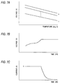
solar battery 1 is inputted into apower controller 3 through a reverse-current prevention diode 7 and ashunt apparatus 2. Thepower controller 3 supplies the current obtained from thesolar battery 1 in shining hours to aload 6 and acharge controller 4a. Thecharge controller 4a generates a prescribed value of current IO shown in Fig. 7C by power from thepower controller 3, supplies the current IO to astorage battery 5, and charges thestorage battery 5. The voltage of thestorage battery 5 increases as shown in Fig. 7B as the charging process advances. When thecharge controller 4a detects that the voltage of thestorage battery 5 reaches a predetermined temperature-compensated voltage value as shown in Fig. 7C (this is called V-T curve, in which 1 - n lines are set by request), a charging mode of the charge controller 4 shifts from constant-current charging till then to constant-voltage charging. According to this, the charge current decreases taperingly as shown in Fig. 7C, and prevents over-charge to thestorage battery 5. - On the other hand, in the time of shade, when the generated power of the
solar battery 1 decreases, thecharge controller 4a discharges thestorage battery 5 by the output of thepower controller 3, and supplies the power to theload 6. - The charge of the storage battery in the conventional low altitude satellite use power supply apparatus is performed as described above, however, the constant-voltage/constant-current charge as described above is conducted on the overall storage battery in which n battery cells are cascade-connected in series, therefore, there is a problem that a specific cell in the storage battery is overcharged due to the unbalance in charge characteristics of each cell constituting the storage battery. Specifically, in the Li-Ion (Lithium Ion) cell structured by Li (Lithium) electrode, energy density, charging voltage, discharging voltage, etc., are higher as compared to those of a Ni-Cd cell, and the Li-Ion cell is expected for use in the storage battery, however, in the case of the Li-Ion cell, there is a problem that electrode deterioration is accelerated and the life is shortened when voltage of the cell exceeds a rated voltage and the cell is in the overcharged condition. For example, as the constant-voltage operating voltage in the V-T curve at the temperature of 0 °C, the sum of n cell voltage is detected as the storage battery voltage, and compared to the setting voltage, however, when m-th cell voltage is higher than that of the other cells due to the internal resistance of the cell, the voltage exceeds the upper limit of the cell voltage, sometimes resulting in deterioration of the cell.
- The present invention is achieved to solve such the problem and the object of the present invention is to obtain the battery accumulating apparatus by which an appropriate charge amount can be secured without overcharging each cell constituting the storage battery.
- A battery accumulating apparatus of the first invention comprises a storage battery to which battery cells are cascade-connected, and a charge current generating means having a means which generates different and a plurality of charge currents to charge the storage battery from the power supply output, and supplies different and a plurality of charge currents to the storage battery.
- In a battery accumulating apparatus of the second invention, in the first invention, the charge current generating means is provided with a means for generating different and a plurality of charge currents, and for changing the charge current so as to be supplied at a low level after, initially, the charge current is supplied at a high level.
- In a battery accumulating apparatus of the third invention, in the first and second inventions, the charge current generating means is provided with a means for changing the charge current from a high level to a low level when any of voltage of battery cells reaches a prescribed value.
- In a battery accumulating apparatus of the fourth invention, in the first to third inventions, a shunt circuit is respectively connected to each battery cell, and when any of voltage of battery cells reaches a prescribed value under the lowest level charge current supply condition to the storage battery, the charge current flowing to the battery cell is bypassed to the shunt circuit connected to the battery cell.
- In a battery accumulating apparatus of the fifth invention, in the first to fourth inventions, a switch, which is provided between the power supply and the storage battery; normally is turned ON; and turned OFF by the charge current generating means when any of voltage of battery cells reaches a prescribed value; and returned to ON by discharge, is provided.
- In a battery accumulating apparatus of the sixth invention, in the first to fifth inventions, the charge current generating means is provided with a means which detects the voltage of the overall battery cell, and which shifts to constant-voltage charge control when the detected voltage reaches a prescribed value.
- In a battery accumulating apparatus of the seventh invention, in the first to sixth inventions, the charge current generating means is provided with a means which releases the constant-voltage charge control when the voltage of the plurality of battery cells becomes unbalanced, and charges the battery cells by the low level charge current until the voltage of the battery cells reaches a prescribed value.
- In a battery accumulating apparatus of the eighth invention, in the first to seventh inventions, a Li-Ion (lithium ion) battery cell structured by a Li (lithium) electrode is used as the battery cell.
-
- Fig. 1 is a structural view of a low altitude satellite
use power supply
apparatus showing Embodiment 1 of the present invention. - Figs. 2A and 2B are graphs for explaining the current and
voltage characteristics of the low altitude satellite use power
supply
apparatus showing Embodiment 1 of the present invention. - Fig. 3 is a structural view of the low altitude satellite
use power supply
apparatus showing Embodiment 2 of the present invention. - Fig. 4 is a structural view of the low altitude satellite
use power supply
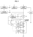
apparatus showing Embodiment 3 of the present invention. - Fig. 5 is a structural view of the low altitude satellite use power supply apparatus showing Embodiment 4 of the present invention.
- Fig. 6 is a structural view of the conventional low altitude satellite use power supply apparatus.
- Figs. 7A to 7C are graphs for explaining the current and voltage characteristics of the conventional low altitude satellite use power supply apparatus.
-
- Now, a description will be given in more detail of preferred embodiments of the invention with reference to the accompanying drawings.
- Fig. 1 is a structural view of a low altitude satellite use power supply
apparatus showing Embodiment 1 of the present invention. In Fig. 1,numerals solar battery 9, and to supply different and a plurality of charge currents to a storage battery to which battery cells are cascade-connected;numeral 8 is a reverse-flow prevention diode connected between the chargingsolar battery 9 and thestorage battery 5; andnumeral 10 is a switch connected between thestorage battery 5 and the reverse-flow prevention diode 8, and is ON status when charging is started, and charging is directly conducted from the chargingsolar battery 9 to thestorage battery 5. Numeral 11 is a control diode. - In this connection, the
charge controller 4b has a current control section to generate charge currents I2 and I3 (I2 > I3) whose levels are lower than a charge current I1 according to the output of the chargingsolar battery 9. -
Numeral 12 is a plurality of cell voltage detectors to detect voltage of each battery cell, and to output a predetermined signal when the detected voltage of the battery cell reaches a prescribed value, andnumeral 13 is an OR circuit which is connected to output terminals of the plurality ofcell voltage detectors 12, and outputs a predetermined signal from thecell voltage detectors 12 to thecharge controller 4b. - Next, operations of the present invention will be described below.
- When the charge current I1 (for example, 30 A) from the charging
solar battery 9 is supplied to thestorage battery 5 through theswitch 10 as shown by I1 in Fig. 2A, each battery cell of thestorage battery 5 is charged, and voltage of each battery cell increases as shown by A in Fig. 2B. Thecell voltage detector 12 respectively detects voltage of the battery cell, and when any of cell voltage of the plurality of battery cells reaches a prescribed value (for example, 3.98 V), thecell voltage detector 12 which detects the cell voltage, outputs a High level signal, for example, to theOR circuit 13. When the High level signal outputted from thecell voltage detector 12 is inputted through theOR circuit 13, thecharge controller 4b outputs a signal which switches theswitch 10 in the ON status to the OFF status, to theswitch 10 through thecontrol diode 11 and turns theswitch 10 OFF. Further, thecharge controller 4b turns theswitch 10 OFF when the voltage of overall battery cells reaches a prescribed value (for example, 3.95 V x the number of battery cells), and shifts the charging mode to the constant-voltage charge. - Further, the
charge controller 4b has a function to generate the charge currents I2 and I3 (I2 > I3) whose levels are lower than the charge current I1, according to the output from the charging solar buttery 9 (a function by which the charge current I1 is switched to the charge currents I2 and I3), and supplies the charge current I2 (refer to I2 in Fig. 2A), for example, 5A to thestorage battery 5 at the same time as the turning OFF of theswitch 10, and charges each battery cell. At this time, the charge voltage of each battery cell initially decreases as shown by B in Fig. 2B, and in a short time, it increases. Each battery cell is charged by the charge current I2 and when any cell voltage of the plurality of battery cells reaches a prescribed value (for example, 3.98 V), the voltage is detected by thecell voltage detector 12, and the detection signal is inputted into thecharge controller 4b through theOR circuit 13. Thecharge controller 4b receives the signal from thecell voltage detector 12, and switches the charge current I2 to I3 and supplies the charge current I3 (for example, 1 A) shown in Fig. 2A to thestorage battery 5, and charges each battery cell (refer to C in Fig. 2B). - In this connection, the
charge controller 4b outputs a signal to return theswitch 10 to the ON status at the time of discharge of thestorage battery 5, to theswitch 10 through thecontrol diode 11. - As described above, the present invention is provided with a multi-stage charge function which supplies the different and plurality of charge currents to the storage battery, and after supplies the charge current initially at a high level, next supplies the charge current at low level, and therefore, the charge controller may control the charge current whose level is lower than the power of the charging solar battery, therefore, there are effects that the charging efficiency is increased and the size and weight can be reduced.
- Further, when the lower level charge current is set, the charge control can be more precisely conducted.
- Fig. 3 is a structural view of the low altitude satellite use power supply
apparatus showing Embodiment 2 of the present invention.Embodiment 2 is characterized in that theshunt circuit 14 is connected in parallel to each battery cell in the structure ofEmbodiment 2, and when the voltage of the battery cell reaches a prescribed value, the charge current is bypassed to theshunt circuit 14 connected in parallel to the battery cell whose voltage reaches the prescribed value so that the voltage increase of the battery cell is suppressed. In the case where the battery cell is charged by the charge current I3, thecell voltage detector 12 outputs a Low level signal when the voltage of the battery cell does not reach a prescribed value. Theshunt circuit 14 is in OFF status when the Low level signal is outputted, and the charge current I3 flows the battery cell. On the other hand, thecell voltage detector 12 outputs a High level signal when the voltage of the battery cell reaches the prescribed value. Theshunt circuit 14 is turned to ON status by this High level signal. According to that, the charge current is bypassed to theshunt circuit 14 connected in parallel to the battery cell whose voltage reaches the prescribed value and consumed, thereby, the charge current I3 does not flow to the battery cell, and the voltage increase can be suppressed. - As described above, the present invention can control the upper limit voltage for each battery cell, and cycle life deterioration of the battery cell can be suppressed to the minimum.
- Fig. 4 is a structural view of the low altitude satellite use power supply
apparatus showing Embodiment 3 of the present invention.Embodiment 3 is basically the same asEmbodiment 2, however, the different points fromEmbodiment 2 are as follows: asignal diode 15 to output a signal to turn OFF theswitch 10 according to the output of theOR circuit 13, and acharge controller 4c having a function in which, when the storage battery is charged by the charge current I3, the voltage of the overall battery is monitored, and when the voltage reaches a prescribed value (which is set lower than the predetermined voltage to switch the charge current), the constant-current charge is shifted (switched) to the constant-voltage charge, are provided. - In this connection, the constant-voltage charge is carried out when the voltage of each battery cell is balanced, and is an ideal condition as a battery operation.
- As described above, in the present invention, the charge controller is provided with a function which monitors the voltage of the overall storage battery when the storage battery is charged by the charge current I1, and which switches the charging mode from the constant-current charge to the constant-voltage charge when the voltage reaches a prescribed value (for example, 3.95 V x the number of batteries), and by using both of this function and the multi-stage charge together, when voltage characteristics of the battery cell are balanced, the charge control is conducted without operating the shunt circuit as much as possible, thereby, the predetermined voltage can be suppressed low, and the cycle life deterioration of the battery cell can be suppressed low.
- Fig. 5 is a structural view of the low altitude satellite use power supply apparatus showing Embodiment 4 of the present invention. Embodiment 4 is basically the same as
Embodiment 3, however, the different points fromEmbodiment 3 are as follows: acharge controller 4d having a function in which, after the constant-current charge is shifted to the constant-voltage charge, when the voltage of each battery cell is unbalanced, the constant-voltage charge control is released, and the voltage balance of each battery cell is taken by forcibly charging each battery cell to the voltage by which theshunt circuit 12 is operated(to the shunt voltage)by the charge current I3, is provided. - In this connection, the voltage of each battery cell is detected by the
cell voltage detector 12 and inputted into thecharge controller 4d through theOR circuit 13, and existence of the voltage unbalance of each battery cell (voltage fluctuation among battery cells to the predetermined voltage) is detected in thecharge controller 4d, however, the voltage of each battery cell is monitored on the ground station side, and when the unbalance is generated, a command to release the constant-voltage charge control, and to forcibly charge each battery cell to the voltage, by which theshunt circuit 12 is operated, by the charge current I3, may be outputted to thecharge controller 4d. - As described above, in the present invention, after the constant-current charge is shifted to the constant-voltage charge, when the voltage of each battery cell is unbalanced, the constant-voltage charge control is released, and each battery cell is charged to the shunt operation voltage by the charge current I3, thereby, the voltage unbalance of each battery cell generated as the charge cycle advances, can be corrected.
- Incidentally, in each embodiment, the low altitude satellite use power supply apparatus is described as an embodiment, however, the present invention can also be applied to other satellites, electric motorcars, ground use solar power generation, etc.
- According to the present invention, when a plurality of cascade-connected battery cells are charged (multi-stage charged) by different charge currents, the overcharge off the battery cells can be suppressed.
- Further, in the present invention, when the voltage of any battery cell reaches a prescribed value under the condition of the minimum level charge current supply to the storage battery, the charge current flowing to the battery cell is bypassed to the shunt circuit connected to the battery cell, thereby, the overcharge of the battery cell can be suppressed.
- In the present invention, the voltage of the overall battery under the condition that the voltage of each battery cell is balanced, is monitored, and when the voltage reaches a prescribed value, the constant-current charge is switched to the constant-voltage charge, thereby, the battery operation can be made ideal condition so that the cycle life deterioration is suppressed.
- Furthermore, in the present invention, after the constant-current charge is shifted to the constant-voltage charge, when the voltage of each battery cell is unbalanced, the constant-voltage charge control is released, and each battery cell is charged to the shunt operation voltage, thereby, the voltage unbalance of each battery cell can be corrected.
Claims (8)
- A battery accumulating apparatus, comprising:a storage battery to which battery cells are cascade-connected; anda charge current generating means for generating a current to charge the storage battery from a power supply output;
wherein the charge current generating means has a means for generating different and a plurality of charge currents, and for supplying different and a plurality of charge currents to the storage battery. - The battery accumulating apparatus according to Claim 1, wherein the charge current generating means has a means for generating different and a plurality of charge currents, and for changing the charge current so as to be supplied at a low level after, initially, the charge current is supplied at a high level.
- The battery accumulating apparatus according to Claim 2, wherein the charge current generating means has a means for changing the charge current from a high level to a low level when any of voltage of battery cells reaches a prescribed value.
- The battery accumulating apparatus according to Claim 3, wherein the battery accumulating apparatus has a shunt circuit respectively connected to each battery cell, and when any of voltage of battery cells reaches a prescribed value under the condition of charge current supply to the storage battery, the charge current flowing to the battery cell is bypassed to the shunt circuit connected to the battery cell.
- The battery accumulating apparatus according to any of Claims 1 to 4, wherein a switch, which is provided between the power source and the storage battery; normally is turned ON; and turned OFF by the charge current generating means when any of voltage of battery cells reaches a prescribed value; and returned to ON at the time of discharge, is provided.
- The battery accumulating apparatus according to Claim 1, wherein the charge current generating means has a means which detects voltage of the overall battery cells, and which shifts to constant-voltage charge control when the detected voltage reaches a prescribed value.
- The battery accumulating apparatus according to Claim 1, wherein the charge current generating means has a means which releases the constant-voltage charge control when voltage of the plurality of battery cells becomes unbalanced, and charges the battery cells by low level charge current until the voltage of all the battery cells reaches the prescribed value.
- The battery accumulating apparatus according to Claim 1, wherein a Li-Ion (lithium ion) battery cell structured by a Li (lithium) electrode is used as the battery cell.
Applications Claiming Priority (2)
| Application Number | Priority Date | Filing Date | Title |
|---|---|---|---|
| JP15779799 | 1999-06-04 | ||
| JP15779799A JP3736205B2 (en) | 1999-06-04 | 1999-06-04 | Battery power storage device |
Publications (3)
| Publication Number | Publication Date |
|---|---|
| EP1058367A2 true EP1058367A2 (en) | 2000-12-06 |
| EP1058367A3 EP1058367A3 (en) | 2002-11-20 |
| EP1058367B1 EP1058367B1 (en) | 2011-06-15 |
Family
ID=15657506
Family Applications (1)
| Application Number | Title | Priority Date | Filing Date |
|---|---|---|---|
| EP00108803A Expired - Lifetime EP1058367B1 (en) | 1999-06-04 | 2000-04-26 | Battery accumulating apparatus |
Country Status (5)
| Country | Link |
|---|---|
| US (1) | US6373224B1 (en) |
| EP (1) | EP1058367B1 (en) |
| JP (1) | JP3736205B2 (en) |
| CA (1) | CA2310357C (en) |
| FR (1) | FR2794578B1 (en) |
Cited By (7)
| Publication number | Priority date | Publication date | Assignee | Title |
|---|---|---|---|---|
| EP1770818A1 (en) * | 2005-09-29 | 2007-04-04 | Kyocera Corporation | Charging apparatus and terminal apparatus |
| EP2375538A1 (en) * | 2010-04-07 | 2011-10-12 | Black & Decker Inc. | A method of charging a battery pack coupled to a battery charger |
| US8122981B2 (en) | 2007-04-16 | 2012-02-28 | Halla Climate Control Corporation | Solar cell system for vehicles and control method thereof |
| EP2365605A3 (en) * | 2010-02-26 | 2014-01-01 | Sanyo Electric Co., Ltd. | Charging apparatus, program |
| EP2724445A4 (en) * | 2011-06-21 | 2015-09-30 | Husqvarna Ab | System and method for charging of a rechargeable battery |
| US9156359B2 (en) | 2012-09-28 | 2015-10-13 | GM Global Technology Operations LLC | Methods and vehicle systems for selectively using energy obtained from a solar subsystem |
| WO2016142628A1 (en) | 2015-03-10 | 2016-09-15 | Sunna Design | Electronic board for power control of a self-contained communicating electrical apparatus |
Families Citing this family (43)
| Publication number | Priority date | Publication date | Assignee | Title |
|---|---|---|---|---|
| JP2002186192A (en) | 2000-12-18 | 2002-06-28 | Mitsubishi Electric Corp | Battery charger |
| US8236443B2 (en) | 2002-08-09 | 2012-08-07 | Infinite Power Solutions, Inc. | Metal film encapsulation |
| US8535396B2 (en) | 2002-08-09 | 2013-09-17 | Infinite Power Solutions, Inc. | Electrochemical apparatus with barrier layer protected substrate |
| US8404376B2 (en) | 2002-08-09 | 2013-03-26 | Infinite Power Solutions, Inc. | Metal film encapsulation |
| US20070264564A1 (en) | 2006-03-16 | 2007-11-15 | Infinite Power Solutions, Inc. | Thin film battery on an integrated circuit or circuit board and method thereof |
| US8021778B2 (en) | 2002-08-09 | 2011-09-20 | Infinite Power Solutions, Inc. | Electrochemical apparatus with barrier layer protected substrate |
| US8431264B2 (en) | 2002-08-09 | 2013-04-30 | Infinite Power Solutions, Inc. | Hybrid thin-film battery |
| US8394522B2 (en) | 2002-08-09 | 2013-03-12 | Infinite Power Solutions, Inc. | Robust metal film encapsulation |
| US8445130B2 (en) | 2002-08-09 | 2013-05-21 | Infinite Power Solutions, Inc. | Hybrid thin-film battery |
| US8728285B2 (en) | 2003-05-23 | 2014-05-20 | Demaray, Llc | Transparent conductive oxides |
| TWI253195B (en) * | 2003-12-26 | 2006-04-11 | Ind Tech Res Inst | Charging method and system for serially connected batteries |
| US7959769B2 (en) | 2004-12-08 | 2011-06-14 | Infinite Power Solutions, Inc. | Deposition of LiCoO2 |
| WO2006063308A2 (en) | 2004-12-08 | 2006-06-15 | Symmorphix, Inc. | DEPOSITION OF LICoO2 |
| JP2007014163A (en) * | 2005-07-01 | 2007-01-18 | Fujitsu Ltd | Charging ic, charger and electronic apparatus |
| US7509688B2 (en) * | 2005-10-20 | 2009-03-31 | Steven Ross Gregg | Facial hair trimmings catcher |
| KR20090069323A (en) | 2006-09-29 | 2009-06-30 | 인피니트 파워 솔루션스, 인크. | Masking of and material constraint for depositing battery layers on flexible substrates |
| US8197781B2 (en) | 2006-11-07 | 2012-06-12 | Infinite Power Solutions, Inc. | Sputtering target of Li3PO4 and method for producing same |
| US20080218127A1 (en) * | 2007-03-07 | 2008-09-11 | O2Micro Inc. | Battery management systems with controllable adapter output |
| JP2009032668A (en) * | 2007-06-22 | 2009-02-12 | Panasonic Corp | Nonaqueous secondary battery, battery pack, power source system, and electrically powered equipment |
| WO2009001502A1 (en) * | 2007-06-22 | 2008-12-31 | Panasonic Corporation | Nonaqueous secondary battery, battery pack, power supply system, and electrical device |
| KR100998302B1 (en) * | 2007-12-07 | 2010-12-06 | 삼성에스디아이 주식회사 | Method for charging of secondary battery and charging device |
| CN101903560B (en) | 2007-12-21 | 2014-08-06 | 无穷动力解决方案股份有限公司 | Method for sputter targets for electrolyte films |
| US8268488B2 (en) * | 2007-12-21 | 2012-09-18 | Infinite Power Solutions, Inc. | Thin film electrolyte for thin film batteries |
| EP2229706B1 (en) | 2008-01-11 | 2014-12-24 | Infinite Power Solutions, Inc. | Thin film encapsulation for thin film batteries and other devices |
| JP5595377B2 (en) | 2008-04-02 | 2014-09-24 | インフィニット パワー ソリューションズ, インコーポレイテッド | Control and protection of passive over and under voltage for energy storage devices associated with energy intake |
| US20100026240A1 (en) * | 2008-07-30 | 2010-02-04 | 3M Innovative Properties Company | Lithium ion battery pack charging system and device including the same |
| JP2012500610A (en) | 2008-08-11 | 2012-01-05 | インフィニット パワー ソリューションズ, インコーポレイテッド | Energy device with integrated collector surface and method for electromagnetic energy acquisition |
| JP2010068571A (en) * | 2008-09-09 | 2010-03-25 | Hitachi Koki Co Ltd | Charging apparatus |
| KR101613671B1 (en) | 2008-09-12 | 2016-04-19 | 사푸라스트 리써치 엘엘씨 | Energy device with integral conductive surface for data communication via electromagnetic energy and method thereof |
| US8508193B2 (en) | 2008-10-08 | 2013-08-13 | Infinite Power Solutions, Inc. | Environmentally-powered wireless sensor module |
| JPWO2010079563A1 (en) * | 2009-01-07 | 2012-06-21 | パナソニック株式会社 | Battery charging method and battery charging system |
| US20100231162A1 (en) * | 2009-03-16 | 2010-09-16 | Gm Global Technology Operations, Inc. | Solar powered battery charging methods and devices for lithium-ion battery systems |
| KR101792287B1 (en) | 2009-09-01 | 2017-10-31 | 사푸라스트 리써치 엘엘씨 | Printed circuit board with integrated thin film battery |
| JP5489779B2 (en) * | 2010-02-26 | 2014-05-14 | 株式会社Nttファシリティーズ | Lithium-ion battery charging system and charging method |
| CN102947976B (en) | 2010-06-07 | 2018-03-16 | 萨普拉斯特研究有限责任公司 | Chargeable, highdensity electrochemical apparatus |
| JP5541982B2 (en) * | 2010-06-28 | 2014-07-09 | シャープ株式会社 | DC power distribution system |
| TWM402554U (en) * | 2010-11-10 | 2011-04-21 | Richtek Technology Corp | Charger circuit |
| JP2012222837A (en) * | 2011-04-04 | 2012-11-12 | Toshiba Mitsubishi-Electric Industrial System Corp | Secondary battery charge control system |
| DE102011017599A1 (en) * | 2011-04-27 | 2012-10-31 | Robert Bosch Gmbh | Method for operating a storage device for storing electrical energy and storage device for storing electrical energy |
| DE102011121940A1 (en) * | 2011-12-22 | 2013-06-27 | Andreas Stihl Ag & Co. Kg | Debalancing protection circuit for a battery pack |
| US8981709B1 (en) * | 2012-08-22 | 2015-03-17 | Edee, LLC | Supplemental electrical generation apparatus and method |
| CN103023112B (en) * | 2012-12-18 | 2015-09-09 | 北车风电有限公司 | The back-up source charging device of wind generating set pitch control system and charging method |
| JP7200512B2 (en) * | 2018-06-21 | 2023-01-10 | カシオ計算機株式会社 | ELECTRONIC DEVICE, ELECTRONIC WATCH AND BATTERY CHARGING METHOD |
Citations (6)
| Publication number | Priority date | Publication date | Assignee | Title |
|---|---|---|---|---|
| EP0498679A2 (en) * | 1991-02-08 | 1992-08-12 | Honda Giken Kogyo Kabushiki Kaisha | Battery charging apparatus |
| US5677613A (en) * | 1994-10-18 | 1997-10-14 | Saft | Method of regulating the charging of a set of electrical storage cells, and a facility implementing the method |
| US5729116A (en) * | 1996-12-20 | 1998-03-17 | Total Battery Management, Inc. | Shunt recognition in lithium batteries |
| US5773957A (en) * | 1996-01-17 | 1998-06-30 | Nissan Motor Co., Ltd. | Charge control system for set of cells |
| EP0851556A2 (en) * | 1996-12-26 | 1998-07-01 | Japan Tobacco Inc. | Battery charger |
| WO1999005767A1 (en) * | 1997-07-25 | 1999-02-04 | Minnesota Mining And Manufacturing Company | Equalizer system and method for series connected energy storing devices |
Family Cites Families (20)
| Publication number | Priority date | Publication date | Assignee | Title |
|---|---|---|---|---|
| US4079303A (en) | 1976-07-28 | 1978-03-14 | The United States Of America As Represented By The United States Department Of Energy | Charging system and method for multicell storage batteries |
| US4270080A (en) | 1978-12-14 | 1981-05-26 | Sun Electric Corporation | Automatic battery charge apparatus and method |
| JPS5972941A (en) | 1982-10-20 | 1984-04-25 | 日本電気株式会社 | Storage battery charging controller |
| JPH06133465A (en) | 1992-08-27 | 1994-05-13 | Sanyo Electric Co Ltd | Method and apparatus for charging secondary battery |
| JPH06165399A (en) | 1992-11-24 | 1994-06-10 | Nippon Moriseru Kk | Charger for lithium ion secondary cell |
| US5367244A (en) * | 1993-01-19 | 1994-11-22 | Premier Engineered Products, Inc. | Battery charging method with stepped current profile and associated charger |
| US5530335A (en) * | 1993-05-11 | 1996-06-25 | Trw Inc. | Battery regulated bus spacecraft power control system |
| JP3577751B2 (en) | 1993-12-24 | 2004-10-13 | ソニー株式会社 | Battery charging device, battery pack, and battery charging method |
| US5550453A (en) | 1994-01-24 | 1996-08-27 | Motorola, Inc. | Battery charging method and apparatus |
| CA2169706A1 (en) * | 1995-03-03 | 1996-09-04 | Troy Lynn Stockstad | Circuit and method for battery charge control |
| JPH0997629A (en) | 1995-09-29 | 1997-04-08 | Sanyo Electric Co Ltd | Plural lithium ion secondary battery charging method |
| JP3620118B2 (en) | 1995-10-24 | 2005-02-16 | 松下電器産業株式会社 | Constant current / constant voltage charger |
| GB9605830D0 (en) | 1996-03-20 | 1996-05-22 | Atomic Energy Authority Uk | Cell overcharge prevention |
| JPH09308126A (en) | 1996-05-17 | 1997-11-28 | Nissan Motor Co Ltd | Charger |
| JP3884802B2 (en) | 1996-11-07 | 2007-02-21 | 日産自動車株式会社 | Lithium-ion battery charging method |
| JPH10248177A (en) | 1997-03-03 | 1998-09-14 | Sanyo Electric Co Ltd | Charging circuit |
| US5804944A (en) | 1997-04-07 | 1998-09-08 | Motorola, Inc. | Battery protection system and process for charging a battery |
| JPH1189106A (en) | 1997-09-08 | 1999-03-30 | Central Res Inst Of Electric Power Ind | Multi-stage charging method/device for secondary battery |
| US6034506A (en) * | 1998-01-16 | 2000-03-07 | Space Systems/Loral, Inc. | Lithium ion satellite battery charge control circuit |
| JP2000236631A (en) | 1999-02-17 | 2000-08-29 | Nec Corp | Battery charge control circuit |
-
1999
- 1999-06-04 JP JP15779799A patent/JP3736205B2/en not_active Expired - Fee Related
- 1999-11-19 US US09/443,286 patent/US6373224B1/en not_active Expired - Fee Related
- 1999-11-30 FR FR9915100A patent/FR2794578B1/en not_active Expired - Fee Related
-
2000
- 2000-04-26 EP EP00108803A patent/EP1058367B1/en not_active Expired - Lifetime
- 2000-05-31 CA CA002310357A patent/CA2310357C/en not_active Expired - Fee Related
Patent Citations (6)
| Publication number | Priority date | Publication date | Assignee | Title |
|---|---|---|---|---|
| EP0498679A2 (en) * | 1991-02-08 | 1992-08-12 | Honda Giken Kogyo Kabushiki Kaisha | Battery charging apparatus |
| US5677613A (en) * | 1994-10-18 | 1997-10-14 | Saft | Method of regulating the charging of a set of electrical storage cells, and a facility implementing the method |
| US5773957A (en) * | 1996-01-17 | 1998-06-30 | Nissan Motor Co., Ltd. | Charge control system for set of cells |
| US5729116A (en) * | 1996-12-20 | 1998-03-17 | Total Battery Management, Inc. | Shunt recognition in lithium batteries |
| EP0851556A2 (en) * | 1996-12-26 | 1998-07-01 | Japan Tobacco Inc. | Battery charger |
| WO1999005767A1 (en) * | 1997-07-25 | 1999-02-04 | Minnesota Mining And Manufacturing Company | Equalizer system and method for series connected energy storing devices |
Cited By (11)
| Publication number | Priority date | Publication date | Assignee | Title |
|---|---|---|---|---|
| EP1770818A1 (en) * | 2005-09-29 | 2007-04-04 | Kyocera Corporation | Charging apparatus and terminal apparatus |
| US7923963B2 (en) | 2005-09-29 | 2011-04-12 | Kyocera Corporation | Charging apparatus and terminal apparatus |
| US8122981B2 (en) | 2007-04-16 | 2012-02-28 | Halla Climate Control Corporation | Solar cell system for vehicles and control method thereof |
| DE112008000930B4 (en) * | 2007-04-16 | 2015-04-30 | Halla Visteon Climate Control Corp. | Method for controlling a solar cell system for vehicles |
| EP2365605A3 (en) * | 2010-02-26 | 2014-01-01 | Sanyo Electric Co., Ltd. | Charging apparatus, program |
| EP2375538A1 (en) * | 2010-04-07 | 2011-10-12 | Black & Decker Inc. | A method of charging a battery pack coupled to a battery charger |
| US8796995B2 (en) | 2010-04-07 | 2014-08-05 | Black & Decker Inc. | State of charge indicator for a battery charger |
| EP2724445A4 (en) * | 2011-06-21 | 2015-09-30 | Husqvarna Ab | System and method for charging of a rechargeable battery |
| US9156359B2 (en) | 2012-09-28 | 2015-10-13 | GM Global Technology Operations LLC | Methods and vehicle systems for selectively using energy obtained from a solar subsystem |
| WO2016142628A1 (en) | 2015-03-10 | 2016-09-15 | Sunna Design | Electronic board for power control of a self-contained communicating electrical apparatus |
| FR3033674A1 (en) * | 2015-03-10 | 2016-09-16 | Sunna Design | ELECTRONIC CONTROL BOARD OF ENERGY CONTROL OF AUTONOMOUS AND COMMUNICABLE ELECTRICAL EQUIPMENT |
Also Published As
| Publication number | Publication date |
|---|---|
| CA2310357A1 (en) | 2000-12-04 |
| JP2000350378A (en) | 2000-12-15 |
| CA2310357C (en) | 2004-02-17 |
| FR2794578B1 (en) | 2003-10-17 |
| FR2794578A1 (en) | 2000-12-08 |
| JP3736205B2 (en) | 2006-01-18 |
| US6373224B1 (en) | 2002-04-16 |
| EP1058367B1 (en) | 2011-06-15 |
| EP1058367A3 (en) | 2002-11-20 |
Similar Documents
| Publication | Publication Date | Title |
|---|---|---|
| EP1058367B1 (en) | Battery accumulating apparatus | |
| CN101960690B (en) | Recharging device and recharging method | |
| US20130187466A1 (en) | Power management system | |
| US6373226B1 (en) | Method of controlling discharge of a plurality of rechargeable batteries, and battery assembly | |
| US8183818B2 (en) | Switching time control multiplexer system | |
| JP3931446B2 (en) | Battery charge state adjustment device | |
| US11063447B2 (en) | Battery pack and energy storage system comprising same | |
| KR101312263B1 (en) | Vehicle and method for controlling the same | |
| CN101692582B (en) | Charge/discharge control circuit and battery device | |
| JP2010098866A (en) | Imbalance determination circuit, imbalance reduction circuit, battery power supply, and imbalance evaluation method | |
| JP3529660B2 (en) | Independent photovoltaic power generation system and power generation method | |
| JPH0997629A (en) | Plural lithium ion secondary battery charging method | |
| JP5508771B2 (en) | Battery pack and battery system | |
| JP2002058174A (en) | Independent solar generation system and its control method | |
| JP4485489B2 (en) | DC power supply system and test method thereof, and program for executing DC power supply system test method | |
| JP3419115B2 (en) | Battery charge / discharge protection device | |
| JP2001008373A (en) | Battery unit and charging method of battery | |
| JP3177405B2 (en) | Secondary battery charge / discharge control method and device | |
| JP3583303B2 (en) | Charge / discharge control method and device for multi-stage connected secondary battery | |
| JP2000341875A (en) | Solar generator | |
| RU2724111C1 (en) | Spacecraft power supply system | |
| JP3635760B2 (en) | Charge control device for battery pack | |
| RU2706762C1 (en) | Control method of autonomous power supply system of spacecraft | |
| Takehara et al. | Energy Storage System with Intelligent Hot-plug Switch (IHS) Combined Use of Different Types of Batteries | |
| JP2002010504A (en) | Power supply device for electric vehicle |
Legal Events
| Date | Code | Title | Description |
|---|---|---|---|
| PUAI | Public reference made under article 153(3) epc to a published international application that has entered the european phase |
Free format text: ORIGINAL CODE: 0009012 |
|
| AK | Designated contracting states |
Kind code of ref document: A2 Designated state(s): AT BE CH CY DE DK ES FI FR GB GR IE IT LI LU MC NL PT SE |
|
| AX | Request for extension of the european patent |
Free format text: AL;LT;LV;MK;RO;SI |
|
| PUAL | Search report despatched |
Free format text: ORIGINAL CODE: 0009013 |
|
| AK | Designated contracting states |
Kind code of ref document: A3 Designated state(s): AT BE CH CY DE DK ES FI FR GB GR IE IT LI LU MC NL PT SE |
|
| AX | Request for extension of the european patent |
Free format text: AL;LT;LV;MK;RO;SI |
|
| 17P | Request for examination filed |
Effective date: 20030131 |
|
| AKX | Designation fees paid |
Designated state(s): DE IT |
|
| RAP1 | Party data changed (applicant data changed or rights of an application transferred) |
Owner name: MITSUBISHI DENKI KABUSHIKI KAISHA |
|
| 17Q | First examination report despatched |
Effective date: 20070829 |
|
| GRAP | Despatch of communication of intention to grant a patent |
Free format text: ORIGINAL CODE: EPIDOSNIGR1 |
|
| GRAS | Grant fee paid |
Free format text: ORIGINAL CODE: EPIDOSNIGR3 |
|
| GRAA | (expected) grant |
Free format text: ORIGINAL CODE: 0009210 |
|
| AK | Designated contracting states |
Kind code of ref document: B1 Designated state(s): DE IT |
|
| REG | Reference to a national code |
Ref country code: DE Ref legal event code: R096 Ref document number: 60046063 Country of ref document: DE Effective date: 20110721 |
|
| PLBE | No opposition filed within time limit |
Free format text: ORIGINAL CODE: 0009261 |
|
| STAA | Information on the status of an ep patent application or granted ep patent |
Free format text: STATUS: NO OPPOSITION FILED WITHIN TIME LIMIT |
|
| 26N | No opposition filed |
Effective date: 20120316 |
|
| REG | Reference to a national code |
Ref country code: DE Ref legal event code: R097 Ref document number: 60046063 Country of ref document: DE Effective date: 20120316 |
|
| PGFP | Annual fee paid to national office [announced via postgrant information from national office to epo] |
Ref country code: DE Payment date: 20120430 Year of fee payment: 13 |
|
| PGFP | Annual fee paid to national office [announced via postgrant information from national office to epo] |
Ref country code: IT Payment date: 20120424 Year of fee payment: 13 |
|
| PG25 | Lapsed in a contracting state [announced via postgrant information from national office to epo] |
Ref country code: DE Free format text: LAPSE BECAUSE OF NON-PAYMENT OF DUE FEES Effective date: 20131101 |
|
| REG | Reference to a national code |
Ref country code: DE Ref legal event code: R119 Ref document number: 60046063 Country of ref document: DE Effective date: 20131101 |
|
| PG25 | Lapsed in a contracting state [announced via postgrant information from national office to epo] |
Ref country code: IT Free format text: LAPSE BECAUSE OF NON-PAYMENT OF DUE FEES Effective date: 20130426 |