EP1059543A1 - Measuring device with an optical interface with low polarization dependent loss (PDL) - Google Patents
Measuring device with an optical interface with low polarization dependent loss (PDL) Download PDFInfo
- Publication number
- EP1059543A1 EP1059543A1 EP99109469A EP99109469A EP1059543A1 EP 1059543 A1 EP1059543 A1 EP 1059543A1 EP 99109469 A EP99109469 A EP 99109469A EP 99109469 A EP99109469 A EP 99109469A EP 1059543 A1 EP1059543 A1 EP 1059543A1
- Authority
- EP
- European Patent Office
- Prior art keywords
- interface
- optical
- optical signal
- boundary surface
- transmission
- Prior art date
- Legal status (The legal status is an assumption and is not a legal conclusion. Google has not performed a legal analysis and makes no representation as to the accuracy of the status listed.)
- Withdrawn
Links
Images


Classifications
-
- G—PHYSICS
- G02—OPTICS
- G02B—OPTICAL ELEMENTS, SYSTEMS OR APPARATUS
- G02B6/00—Light guides; Structural details of arrangements comprising light guides and other optical elements, e.g. couplings
- G02B6/24—Coupling light guides
- G02B6/42—Coupling light guides with opto-electronic elements
- G02B6/4201—Packages, e.g. shape, construction, internal or external details
- G02B6/4204—Packages, e.g. shape, construction, internal or external details the coupling comprising intermediate optical elements, e.g. lenses, holograms
- G02B6/4207—Packages, e.g. shape, construction, internal or external details the coupling comprising intermediate optical elements, e.g. lenses, holograms with optical elements reducing the sensitivity to optical feedback
-
- G—PHYSICS
- G02—OPTICS
- G02B—OPTICAL ELEMENTS, SYSTEMS OR APPARATUS
- G02B5/00—Optical elements other than lenses
- G02B5/30—Polarising elements
- G02B5/3025—Polarisers, i.e. arrangements capable of producing a definite output polarisation state from an unpolarised input state
- G02B5/3033—Polarisers, i.e. arrangements capable of producing a definite output polarisation state from an unpolarised input state in the form of a thin sheet or foil, e.g. Polaroid
Definitions
- the present invention relates to boundary surfaces between optical media with different refractive indices.
- Reflections in general, are caused by boundary surfaces (also referred to as contact surfaces) in the optical path due to differences in refractive indices.
- boundary surfaces also referred to as contact surfaces
- reflections are caused at all boundary surfaces and in particular at fiber terminations, such as fiber connections.
- boundary surfaces such as optical path terminations are generally provided to be angular, angled or tilted (referred to in the following as 'angular').
- such fiber terminations are usually grinded or cut in an angular manner. Typical angles of a standard single mode fiber with approximately 0.008 to 0.010 mm mode field diameter (1300 nm, 1550 nm) are about 8°. The return loss RL in such a case will be greater than 60 dB.
- optical signals transmitted on optical paths, such as fibers are normally polarized, transmission and accordingly loss at such angular boundary surfaces (e.g. fiber-fiber or fiber-air) is dependent on the state of polarization of the optical signal.
- the state of polarization of the optical signal will be modified by any deflection and/or change in temperature and fiber bending within the optical path, so that the state of polarization at the angular boundary surfaces is undefined and varies statistically.
- the optical power of the optical signal will thus be modified in a statistical and accordingly undefined manner at each boundary surface with polarization dependent transmission characteristics. This effect even increases if there are a plurality of polarization dependent boundary surfaces located within the optical path.
- the polarization dependent loss is generally defined as: whereby ⁇ P represents the difference in power between a maximum power value P max and a minimum power value P min of a back reflected signal under the influence of polarization which might occur for an incident signal.
- P average represents the average power that can be approximated as 1 ⁇ 2(P max - P min ).
- the measuring results are modulated by the statistically modifying polarization dependent loss, e.g. at the boundary surface towards the measuring device, thus increasing the (rated) measuring fault.
- the measuring fault will be approximately 0.5% or 0.022 dB (peak to peak).
- a boundary surface (between optical media with different refractive indices) is provided to be angular in order to reduce back reflection of an optical signal at that boundary surface into the direction of the source of the optical signal.
- the boundary surface according to the invention further provides a transmission (through the boundary surface) independent of the state of polarization of the incident optical signal.
- This can be achieved in that the transmissions of the optical signal perpendicular and parallel to the plane of incidence of the angular boundary surface are substantially equal.
- the plane of incidence is generally defined by the incident signal beam and the normal (or plumb line) to the boundary surface.
- the boundary surface provides an interface between optical media with different refractive indices, whereby polarization dependent effects at the boundary surface can be reduced or even be avoided since the transmission through the boundary surface becomes independent of the state of polarization of the incident optical signal.
- This substantial independence of the state of polarization of the incident optical signal generally leads to a substantially constant loss or the optical signal at the boundary surface, which is independent of the state of polarization.
- the invention thus, on one hand, leads to a reduction of the return reflections towards the incident optical signal and, on the other hand, leads to a substantially constant loss substantially independent of the state of polarization of the incident optical signal.
- the angular boundary surface e.g. a termination facet
- Ts Tp
- Ts Tp
- the transmission rates of the optical signal perpendicular and parallel to the plane of incidence of the angular boundary surface will generally be smaller than 100%.
- a coating of the boundary surface is preferably provided to achieve a polarization independent transmission and also to reduce reflection at the boundary surface.
- the boundary surface should provide a smooth and continuous gradient between the refractive indices.
- a plurality of individual layers can be provided e.g. by evaporating or sputtering processes. It is to be understood that a plurality of individual layers also provides more degrees of freedom for the optical design. For technical or cost reasons it might be necessary to limit the number of materials applied for the individual layers. In such a case, it has been found that a sequence of alternating layers of only two different materials already exhibited remarkable results.
- the interference properties of the layers have to be taken into account preferably in order to reduce back reflected light as much as possible.
- the polarization independent coating of the boundary surface is preferably provided to be also dereflective or anti-reflective, thus further reducing return reflections.
- the invention is preferably used for providing a defined termination (facet) of an optical path, in particular of an optical fiber path but can be employed for any kind of boundary or contact surface.
- a defined termination face of an optical path
- Such defined terminations of optical paths are in particular useful for measurement purposes since the measurement fault, and thus the measurement resolution, can be significantly improved by eliminating or at least reducing polarization dependent effects.
- the invention can be applied for any interface between optical media with different refractive indices.
- Typical applications can be e.g. termination surfaces, termination adapters, detector surfaces, or the like.
- FIG. 1 illustrates a schematic diagram of a termination adapter 10 according to the invention.
- the termination adapter 10 comprises a fiber segment 20, which is spliced to or otherwise coupled to a fiber 30.
- a boundary 40 between the fiber 30 and the fiber segment 20 is provided in a way that substantially no polarization loss dependency occurs, so that the boundary 40 substantially does not provide an optical boundary surface or, in other words, the fiber segment can be regarded as being part of the optical fiber 30. This can be achieved, as well-known in the art, e.g. by melting the fibers together or by providing a (glass/glass) contact without air transition.
- a boundary surface 50 is provided at the very end of the termination adapter 10 towards e.g. an optical detector 60 of an optical measuring device 70.
- the optical detector 60 is adapted to receive and measure an optical signal 75 which might have been coupled into the optical fiber 30 by an optical source 80 which might be located at the opposite site of the fiber 30.
- a plane A of the boundary surface 50 is angular or tilted by an angle ⁇ with respect to a plane B of the incident optical signal 75.
- the plane of incidence is defined here by the vector of the incident signal beam 75 and the normal N to the plane A of the boundary surface 50. In the representation of Fig. 1, the plane of incidence corresponds with the plane of drawing.
- the boundary surface 50 is coated with one or more layers of optically different materials in order to provide a good matching between the transmission Ts( ⁇ ) perpendicular to the plane B and the transmission Tp( ⁇ ) parallel to the plane B at the boundary surface 50, so that Ts( ⁇ ; ⁇ 1... ⁇ 2) ⁇ Tp( ⁇ ; ⁇ 1... ⁇ 2) or, in other words, that the perpendicular and parallel transmission Ts( ⁇ ) and Tp( ⁇ ) are substantially equal within a wavelength band between ⁇ 1 and ⁇ 2.
- the exemplary boundary surface 50 between silica glass and air comprises the following layers: Layer # Layer thickness Layer material Refractive index silica glass 1.45 1 71.959 TiO 2 2.153421 2 86.590 SiO 2 1.444266 3 185.813 TiO 2 2.153421 4 47.256 SiO 2 1.444266 5 117.581 TiO 2 2.153421 6 47.299 SiO 2 1.444266 7 78.062 TiO 2 2.153421 8 280.718 SiO 2 1.444266 air 1.00
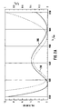
- Figures 2A and 2B depict measured characteristics of reflection, polarization dependent loss (PDL), and transmission for the above boundary surface 50 example.
- the wavelength ⁇ is depicted on the x-axis in nm (10 -9 m), and the values for a measured PDL curve are shown left-hand side on the y-axis in 0.001 dB.
- Fig. 2A additionally depicts on the right hand side of the y-axis the values of a measured reflection R curve 210 in %.
- Fig. 2B additionally depicts on the right hand side of the y-axis the values as well of a measured transmission Ts curve 220 as of a measured transmission Tp curve 230, both in %.
- PDL can be reduced in the wavelength band of about 1270 nm to 1600 nm to maximum PDL values of 0.0039 dB. Accordingly, the minimum values of transmission Ts and Tp (cf. Fig. 2B) in that wavelength band do not go below 99.6%. The values of reflection R (cf. Fig. 2A) in that wavelength band do not go beyond 0.34%.
- PDL regions' with PDL values smaller than 0.0005 dB are located in the wavelength bands of about 1255-1300 nm and 1565-1635nm. As can be seen from Fig. 2B, those 'almost zero PDL regions' do not coincide with the maxima of the transmission values for Ts and Tp. 'Almost zero reflection regions' with reflection values smaller than 0.1 % are located in the wavelength bands of about 1280-1330 nm and 1510-1600nm. In particular in the regions of intersection between PDL and R, a good compromise between low PDL and low reflection can be found.
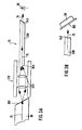
- Fig. 3A illustrates another application according to the invention.
- the fiber 30 is coupled to the optical source 80 (not shown in Fig. 3) providing the optical signal 75.
- the fiber 30 provides a termination surface 300 directed towards a coupling member 310 of the optical measuring device 70.
- the optical signal 75 leaves the termination surface 300 and is coupled via a lens system 320 of the coupling member 310 into a multi-mode fiber 330 which, again, emits the optical signal 75 to the optical detector 60, preferably a PIN-diode.
- a termination surface 340 of the of the multi-mode fiber 330 directed towards the optical detector 60 is provided in accordance with the present invention, i.e. angular with respect to the plane B perpendicular to the incident optical signal 75 and provided with an interface between the refractive indices of the multi-mode fiber 330 and air, whereby the transmission of the incident optical signal 75 through the termination surface 50 is substantially independent of the state of polarization of the incident optical signal 75.
- the termination surface 300 of the fiber 30 and/or the other termination surface 350 of the multi-mode fiber 330 might also be provided in accordance with the invention.
- Fig. 3B depicts an alternative embodiment of the arrangement of the optical detector 60 and the boundary surface 50.
- PDL and return loss at the transition between the optical detector 60 and the boundary surface 50 are minimized in the embodiment of Fig. 3A by providing the boundary surface 50 angular and with polarization independent transmission
- the embodiment of Fig. 3B inverts that arrangement in that a termination surface 360 of the optical detector 60 is provided angular and with polarization independent transmission.
- the same effect of minimized PDL and return loss can be achieved.
- Further improvements can be attained by also providing the boundary surface 340 and/or other boundary surfaces in the optical system in accordance with the invention.
- any boundary surface can be provided in accordance with the present invention by providing an interface between the refractive indices of the adjoining media which is angular with respect to the plane B perpendicular to the incident optical signal 75.
Abstract
Description
- The present invention relates to boundary surfaces between optical media with different refractive indices.
- In some optical applications, in particular in fiber optical paths, it is important to avoid or at least reduce unwanted return reflections, i.e. reflections in the direction of an incident optical signal, since such return reflections can disturb e.g. the source (for example a laser diode) of the optical signal. This can lead, amongst others, to signal deviations of the optical signal source.
- Reflections, in general, are caused by boundary surfaces (also referred to as contact surfaces) in the optical path due to differences in refractive indices. E.g. in fiber optical paths, reflections are caused at all boundary surfaces and in particular at fiber terminations, such as fiber connections. High values of reflections result in particular from transitions between the optical path media and air for transitions perpendicular to the propagation direction of the optical path. Assuming an optical glass fiber with a refractive index of n=15 would result in a reflectivity R = 4% for such a perpendicular glass air transition. Using the definition of return loss RL in logarithmic dB values:
- In order to diminish the influence of unwanted reflections, boundary surfaces such as optical path terminations are generally provided to be angular, angled or tilted (referred to in the following as 'angular'). In optical fibers, such fiber terminations are usually grinded or cut in an angular manner. Typical angles of a standard single mode fiber with approximately 0.008 to 0.010 mm mode field diameter (1300 nm, 1550 nm) are about 8°. The return loss RL in such a case will be greater than 60 dB.
- Disadvantageous in providing angular terminations of the optical path, however, is the polarization dependent transmission through that termination which is caused by that angular boundary surface. Since optical signals transmitted on optical paths, such as fibers, are normally polarized, transmission and accordingly loss at such angular boundary surfaces (e.g. fiber-fiber or fiber-air) is dependent on the state of polarization of the optical signal. The state of polarization of the optical signal, however, will be modified by any deflection and/or change in temperature and fiber bending within the optical path, so that the state of polarization at the angular boundary surfaces is undefined and varies statistically. The optical power of the optical signal will thus be modified in a statistical and accordingly undefined manner at each boundary surface with polarization dependent transmission characteristics. This effect even increases if there are a plurality of polarization dependent boundary surfaces located within the optical path.
- The polarization dependent loss (PDL) is generally defined as:whereby ΔP represents the difference in power between a maximum power value Pmax and a minimum power value Pmin of a back reflected signal under the influence of polarization which might occur for an incident signal. Paverage represents the average power that can be approximated as ½(Pmax - Pmin).

- If measuring devices are coupled to the optical path for determining the optical power of the optical signal, the measuring results are modulated by the statistically modifying polarization dependent loss, e.g. at the boundary surface towards the measuring device, thus increasing the (rated) measuring fault. In the above-mentioned example of a tilted termination boundary surface with an angle of 8° and a transition between glass (refractive index of 1.5) and air, the measuring fault will be approximately 0.5% or 0.022 dB (peak to peak).
- It is an object of the present invention to reduce the influence of return loss (RL) and polarization dependent loss (PDL) on boundary surfaces in an optical path. The object is solved by the independent claims. Preferred embodiments are shown by the dependent claims.
- According to the invention, a boundary surface (between optical media with different refractive indices) is provided to be angular in order to reduce back reflection of an optical signal at that boundary surface into the direction of the source of the optical signal.
- The boundary surface according to the invention further provides a transmission (through the boundary surface) independent of the state of polarization of the incident optical signal. This can be achieved in that the transmissions of the optical signal perpendicular and parallel to the plane of incidence of the angular boundary surface are substantially equal. The plane of incidence is generally defined by the incident signal beam and the normal (or plumb line) to the boundary surface. Thus, the boundary surface provides an interface between optical media with different refractive indices, whereby polarization dependent effects at the boundary surface can be reduced or even be avoided since the transmission through the boundary surface becomes independent of the state of polarization of the incident optical signal. This substantial independence of the state of polarization of the incident optical signal, however, generally leads to a substantially constant loss or the optical signal at the boundary surface, which is independent of the state of polarization.
- The invention thus, on one hand, leads to a reduction of the return reflections towards the incident optical signal and, on the other hand, leads to a substantially constant loss substantially independent of the state of polarization of the incident optical signal.
- For avoiding or reducing the polarization dependent loss (PDL) the angular boundary surface (e.g. a termination facet) will be preferably provided with a specific coating substantially fulfilling the condition:
- In case that Ts = Tp, there is no polarization dependent loss at the boundary surface even though the boundary surface is angular.
- A coating of the boundary surface is preferably provided to achieve a polarization independent transmission and also to reduce reflection at the boundary surface.
- In the ideal case, the boundary surface should provide a smooth and continuous gradient between the refractive indices. This, however, encounters the problem of technical feasibility. Instead of such a continuous gradient between the refractive indices, a plurality of individual layers can be provided e.g. by evaporating or sputtering processes. It is to be understood that a plurality of individual layers also provides more degrees of freedom for the optical design. For technical or cost reasons it might be necessary to limit the number of materials applied for the individual layers. In such a case, it has been found that a sequence of alternating layers of only two different materials already exhibited remarkable results.
- General properties of applicable materials for the polarization independent boundary surface are that the material can be applied as preferably thin layers and the material preferably provides dielectric, loss-free layers. Suitable materials have been found in the following list of common evaporating materials:
- hafnium oxide HfO2
- titanium oxide TiO2
- aluminum oxide Al2O3
- zirconium oxide ZrO2
- silicon oxide SiO2
- When designing the plurality of individual layers, in particular the interference properties of the layers, alone and in combination with each other, have to be taken into account preferably in order to reduce back reflected light as much as possible.
- The polarization independent coating of the boundary surface is preferably provided to be also dereflective or anti-reflective, thus further reducing return reflections. By carefully selecting coating parameters, such as number of coating layers, coating materials and/or layer thickness of the return reflection reducing coating, the above given condition Ts = Tp can also be fulfilled for coatings wherein the average transmission is smaller than 100%, or, in other words, for coatings which provide the condition:
Tp - That means that even 'non-perfect' dereflective coatings according to the invention with reflectivity values of R > 0 do not provide polarization dependent transmission losses and can thus be applied.
- In case that the values of the perpendicular and parallel transmission Ts and Tp (respectively) exhibit dependencies on the wavelengths of the incident optical signal, a certain tradeoff or compromise for different wavelengths or one or more wavelength bands might have to be made in order to reduce the polarization dependent loss for those wavelengths or wavelength bands. In such a case, the condition Ts = Tp will hardly be fulfilable for all wavelengths so that a certain compromise has to be made and a certain wavelength dependent polarization dependent loss will have to be encountered. However, by carefully balancing Ts(λ) and Tp(λ) the affect of polarization dependent loss can be efficiently minimized for certain wavelengths or wavelength bands of interest.
- The invention is preferably used for providing a defined termination (facet) of an optical path, in particular of an optical fiber path but can be employed for any kind of boundary or contact surface. Such defined terminations of optical paths are in particular useful for measurement purposes since the measurement fault, and thus the measurement resolution, can be significantly improved by eliminating or at least reducing polarization dependent effects.
- The invention can be applied for any interface between optical media with different refractive indices. Typical applications can be e.g. termination surfaces, termination adapters, detector surfaces, or the like.
- Other objects and many of the attendant advantages of the present invention will be readily appreciated and become better understood by reference to the following detailed description when considering in connection with the accompanied drawings. Features that are substantially or functionally equal or similar will be referred to with the same reference sign(s).
- Fig. 1
- illustrates a schematic diagram of a
termination adapter 10 according to the invention, - Figures 2A and 2B
- depict measured characteristics of reflection, polarization
dependent loss (PDL), and transmission for the
boundary surface 50 of Fig. 1, and - Figures 3A and 3B
- illustrate other applications according to the invention.
- Figure 1 illustrates a schematic diagram of a
termination adapter 10 according to the invention. Thetermination adapter 10 comprises afiber segment 20, which is spliced to or otherwise coupled to afiber 30. Aboundary 40 between thefiber 30 and thefiber segment 20 is provided in a way that substantially no polarization loss dependency occurs, so that theboundary 40 substantially does not provide an optical boundary surface or, in other words, the fiber segment can be regarded as being part of theoptical fiber 30. This can be achieved, as well-known in the art, e.g. by melting the fibers together or by providing a (glass/glass) contact without air transition. - A
boundary surface 50 is provided at the very end of thetermination adapter 10 towards e.g. anoptical detector 60 of anoptical measuring device 70. Theoptical detector 60 is adapted to receive and measure anoptical signal 75 which might have been coupled into theoptical fiber 30 by anoptical source 80 which might be located at the opposite site of thefiber 30. - A plane A of the
boundary surface 50 is angular or tilted by an angle α with respect to a plane B of the incidentoptical signal 75. Thus, a return reflection at theboundary surface 50 towards thefiber 30, and accordingly towards theoptical source 80, can be reduced or avoided. The plane of incidence is defined here by the vector of theincident signal beam 75 and the normal N to the plane A of theboundary surface 50. In the representation of Fig. 1, the plane of incidence corresponds with the plane of drawing. - The
boundary surface 50 is coated with one or more layers of optically different materials in order to provide a good matching between the transmission Ts(λ) perpendicular to the plane B and the transmission Tp(λ) parallel to the plane B at theboundary surface 50, so that - A specific example of a
boundary surface 50 in accordance with the invention shall now be given, and the effect thereof will be illustrated by means of measuring plots as shown in Figs. 2A and 2B. Theexemplary boundary surface 50 between silica glass and air comprises the following layers:Layer # Layer thickness Layer material Refractive index silica glass 1.45 1 71.959 TiO2 2.153421 2 86.590 SiO2 1.444266 3 185.813 TiO2 2.153421 4 47.256 SiO2 1.444266 5 117.581 TiO2 2.153421 6 47.299 SiO2 1.444266 7 78.062 TiO2 2.153421 8 280.718 SiO2 1.444266 air 1.00 - Figures 2A and 2B depict measured characteristics of reflection, polarization dependent loss (PDL), and transmission for the
above boundary surface 50 example. Theboundary surface 50 is tilted by an angle α = 8°. In both Figs. 2A and 2B, the wavelength λ is depicted on the x-axis in nm (10-9 m), and the values for a measured PDL curve are shown left-hand side on the y-axis in 0.001 dB. Fig. 2A additionally depicts on the right hand side of the y-axis the values of a measuredreflection R curve 210 in %. Fig. 2B additionally depicts on the right hand side of the y-axis the values as well of a measured transmission Ts curve 220 as of a measuredtransmission Tp curve 230, both in %. - As apparent from Figs. 2A and 2B, PDL can be reduced in the wavelength band of about 1270 nm to 1600 nm to maximum PDL values of 0.0039 dB. Accordingly, the minimum values of transmission Ts and Tp (cf. Fig. 2B) in that wavelength band do not go below 99.6%. The values of reflection R (cf. Fig. 2A) in that wavelength band do not go beyond 0.34%.
- 'Almost zero PDL regions' with PDL values smaller than 0.0005 dB are located in the wavelength bands of about 1255-1300 nm and 1565-1635nm. As can be seen from Fig. 2B, those 'almost zero PDL regions' do not coincide with the maxima of the transmission values for Ts and Tp. 'Almost zero reflection regions' with reflection values smaller than 0.1 % are located in the wavelength bands of about 1280-1330 nm and 1510-1600nm. In particular in the regions of intersection between PDL and R, a good compromise between low PDL and low reflection can be found.
- Using different coating materials and different sequences of coating layers allows locating and shifting the 'almost zero PDL regions' and the 'almost zero reflection regions' in accordance with the required wavelengths and applications.
- Fig. 3A illustrates another application according to the invention. The
fiber 30 is coupled to the optical source 80 (not shown in Fig. 3) providing theoptical signal 75. Thefiber 30 provides atermination surface 300 directed towards acoupling member 310 of theoptical measuring device 70. Theoptical signal 75 leaves thetermination surface 300 and is coupled via alens system 320 of thecoupling member 310 into amulti-mode fiber 330 which, again, emits theoptical signal 75 to theoptical detector 60, preferably a PIN-diode. - A
termination surface 340 of the of themulti-mode fiber 330 directed towards theoptical detector 60 is provided in accordance with the present invention, i.e. angular with respect to the plane B perpendicular to the incidentoptical signal 75 and provided with an interface between the refractive indices of themulti-mode fiber 330 and air, whereby the transmission of the incidentoptical signal 75 through thetermination surface 50 is substantially independent of the state of polarization of the incidentoptical signal 75. Additionally, thetermination surface 300 of thefiber 30 and/or theother termination surface 350 of themulti-mode fiber 330 might also be provided in accordance with the invention. - Fig. 3B depicts an alternative embodiment of the arrangement of the
optical detector 60 and theboundary surface 50. Whereas PDL and return loss at the transition between theoptical detector 60 and theboundary surface 50 are minimized in the embodiment of Fig. 3A by providing theboundary surface 50 angular and with polarization independent transmission, the embodiment of Fig. 3B inverts that arrangement in that atermination surface 360 of theoptical detector 60 is provided angular and with polarization independent transmission. Thus, the same effect of minimized PDL and return loss can be achieved. Further improvements can be attained by also providing theboundary surface 340 and/or other boundary surfaces in the optical system in accordance with the invention. - Referring again to Figs. 3A and 3B, in a more generalized view it can be said that any boundary surface can be provided in accordance with the present invention by providing an interface between the refractive indices of the adjoining media which is angular with respect to the plane B perpendicular to the incident
optical signal 75.
Claims (9)
- An interface (50) between optical media with different refractive indices, preferably a boundary surface, face or facet, whereby:
the interface (50) is arranged angular with respect to an incident optical signal (75) for reducing a return reflection into the direction of the incident optical signal (75),
characterized in that
the transmission of the incident optical signal (75) through the interface (50) is substantially independent of the state of polarization of the incident optical signal (75). - The interface (50) of claim 1, wherein the transmission (Ts) perpendicular to the plane of incidence of the optical signal (75) substantially equals the transmission (Tp) parallel to the plane of incidence of the optical signal (75).
- The interface (50) of claim 1 or 2, providing a gradient between the optical media with the different refractive indices.
- The interface (50) of claim 1 or 2, comprising a plurality of individual layers, preferably a sequence of alternating layers of different materials.
- The interface (50) of claim 4, wherein the plurality of individual layers comprise one or more materials of hafnium oxide HfO2, titanium oxide TiO2, aluminum oxide Al2O3, zirconium oxide ZrO2, or silicon oxide SiO2.
- The interface (50) according to any one of the claims 2-5, wherein the transmissions (Ts, Tp) perpendicular and parallel to the plane of incidence of the optical signal (75) are substantially balanced for a plurality of different wavelengths and/or for one or more wavelength bands.
- A termination (10) of an optical path, in particular of an optical fiber path, comprising an interface (50) according to any one of the above claims 1-6.
- A termination adapter (10) for terminating an optical path, in particular an optical fiber path, comprising an interface (50) according to any one of the above claims 1-6.
- An optical device, preferably an optical detector (60), comprising an interface (50) according to any one of the above claims 1-6.
Priority Applications (3)
| Application Number | Priority Date | Filing Date | Title |
|---|---|---|---|
| EP99109469A EP1059543A1 (en) | 1999-05-12 | 1999-05-12 | Measuring device with an optical interface with low polarization dependent loss (PDL) |
| US09/568,972 US6430338B1 (en) | 1999-05-12 | 2000-05-11 | Measuring device with an optical interface with low polarization dependent loss (PDL) |
| JP2000139670A JP2000356725A (en) | 1999-05-12 | 2000-05-12 | Measuring device having optical boundary surface in which polarization dependence loss (pdl) is reduced |
Applications Claiming Priority (1)
| Application Number | Priority Date | Filing Date | Title |
|---|---|---|---|
| EP99109469A EP1059543A1 (en) | 1999-05-12 | 1999-05-12 | Measuring device with an optical interface with low polarization dependent loss (PDL) |
Publications (1)
| Publication Number | Publication Date |
|---|---|
| EP1059543A1 true EP1059543A1 (en) | 2000-12-13 |
Family
ID=8238162
Family Applications (1)
| Application Number | Title | Priority Date | Filing Date |
|---|---|---|---|
| EP99109469A Withdrawn EP1059543A1 (en) | 1999-05-12 | 1999-05-12 | Measuring device with an optical interface with low polarization dependent loss (PDL) |
Country Status (3)
| Country | Link |
|---|---|
| US (1) | US6430338B1 (en) |
| EP (1) | EP1059543A1 (en) |
| JP (1) | JP2000356725A (en) |
Cited By (2)
| Publication number | Priority date | Publication date | Assignee | Title |
|---|---|---|---|---|
| EP1331500A2 (en) * | 2002-01-24 | 2003-07-30 | Tektronix, Inc. | Fiber-pigtailed assembly |
| EP1628121A1 (en) * | 2004-08-18 | 2006-02-22 | Agilent Technologies Inc | Determination of polarization dependent properties |
Citations (5)
| Publication number | Priority date | Publication date | Assignee | Title |
|---|---|---|---|---|
| US4492436A (en) * | 1983-01-03 | 1985-01-08 | At&T Bell Laboratories | Polarization independent beam splitter |
| EP0488211A2 (en) * | 1990-11-27 | 1992-06-03 | Fujitsu Limited | Polarization independent optical device |
| EP0554849A1 (en) * | 1992-02-03 | 1993-08-11 | Sumitomo Electric Industries, Limited | Semiconductor light detecting device |
| JPH0784124A (en) * | 1993-09-20 | 1995-03-31 | Sumitomo Electric Ind Ltd | Beam splitter |
| US5574809A (en) * | 1994-08-01 | 1996-11-12 | Shin-Etsu Chemical Co., Ltd. | Optical fiber type part for optical systems |
Family Cites Families (4)
| Publication number | Priority date | Publication date | Assignee | Title |
|---|---|---|---|---|
| WO1996019743A1 (en) * | 1994-12-21 | 1996-06-27 | E-Tek Dynamics, Inc. | Integrable fiberoptic coupler and resulting devices and systems |
| US5657148A (en) * | 1996-05-07 | 1997-08-12 | Lucent Technologies Inc. | Apparatus and method for a single-port modulator having amplification |
| US6266462B1 (en) * | 1998-02-12 | 2001-07-24 | Ultraband Fiber Optics | Acousto-optic filter |
| US6167174A (en) * | 1998-10-27 | 2000-12-26 | Adc Telecommunications, Inc. | Multiple port, fiber optic isolator |
-
1999
- 1999-05-12 EP EP99109469A patent/EP1059543A1/en not_active Withdrawn
-
2000
- 2000-05-11 US US09/568,972 patent/US6430338B1/en not_active Expired - Fee Related
- 2000-05-12 JP JP2000139670A patent/JP2000356725A/en active Pending
Patent Citations (5)
| Publication number | Priority date | Publication date | Assignee | Title |
|---|---|---|---|---|
| US4492436A (en) * | 1983-01-03 | 1985-01-08 | At&T Bell Laboratories | Polarization independent beam splitter |
| EP0488211A2 (en) * | 1990-11-27 | 1992-06-03 | Fujitsu Limited | Polarization independent optical device |
| EP0554849A1 (en) * | 1992-02-03 | 1993-08-11 | Sumitomo Electric Industries, Limited | Semiconductor light detecting device |
| JPH0784124A (en) * | 1993-09-20 | 1995-03-31 | Sumitomo Electric Ind Ltd | Beam splitter |
| US5574809A (en) * | 1994-08-01 | 1996-11-12 | Shin-Etsu Chemical Co., Ltd. | Optical fiber type part for optical systems |
Non-Patent Citations (1)
| Title |
|---|
| PATENT ABSTRACTS OF JAPAN vol. 199, no. 506 31 July 1995 (1995-07-31) * |
Cited By (5)
| Publication number | Priority date | Publication date | Assignee | Title |
|---|---|---|---|---|
| EP1331500A2 (en) * | 2002-01-24 | 2003-07-30 | Tektronix, Inc. | Fiber-pigtailed assembly |
| EP1331500A3 (en) * | 2002-01-24 | 2004-10-13 | Tektronix, Inc. | Fiber-pigtailed assembly |
| US6948859B2 (en) | 2002-01-24 | 2005-09-27 | Tektronix, Inc. | Fiber-pigtailed assembly |
| EP1628121A1 (en) * | 2004-08-18 | 2006-02-22 | Agilent Technologies Inc | Determination of polarization dependent properties |
| US7352450B2 (en) | 2004-08-18 | 2008-04-01 | Thomas Jensen | Determination of polarization dependent properties |
Also Published As
| Publication number | Publication date |
|---|---|
| US6430338B1 (en) | 2002-08-06 |
| JP2000356725A (en) | 2000-12-26 |
Similar Documents
| Publication | Publication Date | Title |
|---|---|---|
| US4296995A (en) | Optical fiber beam splitter couplers employing coatings with dichroic properties | |
| US20090232450A1 (en) | Simple fiber optic cavity | |
| US6128133A (en) | Optical beamsplitter | |
| US6031952A (en) | Broadband coupler | |
| US7324728B2 (en) | Optical connector with total internal reflection abutting surface | |
| US7011455B2 (en) | Opto-electronic TO-package and method for laser | |
| US10416401B2 (en) | In-line uni-directional optical tap detector | |
| US6430338B1 (en) | Measuring device with an optical interface with low polarization dependent loss (PDL) | |
| WO2005036212A2 (en) | Photodetector/optical fiber apparatus with enhanced optical coupling efficiency and method for forming the same | |
| CA2491722A1 (en) | Optical fiber component | |
| JPH0921608A (en) | Faraday rotary mirror | |
| US11125943B2 (en) | Optical modulator and optical measurement apparatus | |
| KR100361441B1 (en) | tap coupler | |
| KR101718481B1 (en) | Expanded beam connector based on ball lens | |
| EP1223456B1 (en) | Low polarisation dependent loss beam splitter | |
| US6778337B2 (en) | Optical attenuator and optical attenuator module | |
| CA2245850A1 (en) | An optical connection | |
| JP4764654B2 (en) | Optical module | |
| US20090060415A1 (en) | Fiber optic cavity | |
| JPH0926556A (en) | Faraday rotation mirror | |
| US20230288641A1 (en) | Optical waveguide for a magneto-optical current sensor | |
| Pennings et al. | Ultra fabrication-tolerant fully packaged micro-optical polarization diversity hybrid | |
| Shin et al. | Dielectric mirror embedded optical fiber couplers | |
| JP4175555B2 (en) | Optical splitter | |
| US6212316B1 (en) | Stand-off matched index optical waveguide interface |
Legal Events
| Date | Code | Title | Description |
|---|---|---|---|
| PUAI | Public reference made under article 153(3) epc to a published international application that has entered the european phase |
Free format text: ORIGINAL CODE: 0009012 |
|
| 17P | Request for examination filed |
Effective date: 19991119 |
|
| AK | Designated contracting states |
Kind code of ref document: A1 Designated state(s): DE FR GB |
|
| AX | Request for extension of the european patent |
Free format text: AL;LT;LV;MK;RO;SI |
|
| RAP1 | Party data changed (applicant data changed or rights of an application transferred) |
Owner name: AGILENT TECHNOLOGIES, INC. |
|
| RAP1 | Party data changed (applicant data changed or rights of an application transferred) |
Owner name: AGILENT TECHNOLOGIES INC. |
|
| RAP1 | Party data changed (applicant data changed or rights of an application transferred) |
Owner name: AGILENT TECHNOLOGIES INC. A DELAWARE CORPORATION |
|
| STAA | Information on the status of an ep patent application or granted ep patent |
Free format text: STATUS: THE APPLICATION IS DEEMED TO BE WITHDRAWN |
|
| AKX | Designation fees paid |
Free format text: DE FR GB |
|
| 18D | Application deemed to be withdrawn |
Effective date: 20010309 |