EP1061140A1 - Composite magnetic member, process for producing the member and electromagnetic valve using the member - Google Patents
Composite magnetic member, process for producing the member and electromagnetic valve using the member Download PDFInfo
- Publication number
- EP1061140A1 EP1061140A1 EP00119829A EP00119829A EP1061140A1 EP 1061140 A1 EP1061140 A1 EP 1061140A1 EP 00119829 A EP00119829 A EP 00119829A EP 00119829 A EP00119829 A EP 00119829A EP 1061140 A1 EP1061140 A1 EP 1061140A1
- Authority
- EP
- European Patent Office
- Prior art keywords
- magnetic
- ferromagnetized
- magnetized
- equivalent
- working
- Prior art date
- Legal status (The legal status is an assumption and is not a legal conclusion. Google has not performed a legal analysis and makes no representation as to the accuracy of the status listed.)
- Granted
Links
Images


Classifications
-
- H—ELECTRICITY
- H01—ELECTRIC ELEMENTS
- H01F—MAGNETS; INDUCTANCES; TRANSFORMERS; SELECTION OF MATERIALS FOR THEIR MAGNETIC PROPERTIES
- H01F1/00—Magnets or magnetic bodies characterised by the magnetic materials therefor; Selection of materials for their magnetic properties
- H01F1/01—Magnets or magnetic bodies characterised by the magnetic materials therefor; Selection of materials for their magnetic properties of inorganic materials
- H01F1/03—Magnets or magnetic bodies characterised by the magnetic materials therefor; Selection of materials for their magnetic properties of inorganic materials characterised by their coercivity
- H01F1/12—Magnets or magnetic bodies characterised by the magnetic materials therefor; Selection of materials for their magnetic properties of inorganic materials characterised by their coercivity of soft-magnetic materials
- H01F1/14—Magnets or magnetic bodies characterised by the magnetic materials therefor; Selection of materials for their magnetic properties of inorganic materials characterised by their coercivity of soft-magnetic materials metals or alloys
- H01F1/147—Alloys characterised by their composition
-
- B—PERFORMING OPERATIONS; TRANSPORTING
- B60—VEHICLES IN GENERAL
- B60T—VEHICLE BRAKE CONTROL SYSTEMS OR PARTS THEREOF; BRAKE CONTROL SYSTEMS OR PARTS THEREOF, IN GENERAL; ARRANGEMENT OF BRAKING ELEMENTS ON VEHICLES IN GENERAL; PORTABLE DEVICES FOR PREVENTING UNWANTED MOVEMENT OF VEHICLES; VEHICLE MODIFICATIONS TO FACILITATE COOLING OF BRAKES
- B60T8/00—Arrangements for adjusting wheel-braking force to meet varying vehicular or ground-surface conditions, e.g. limiting or varying distribution of braking force
- B60T8/32—Arrangements for adjusting wheel-braking force to meet varying vehicular or ground-surface conditions, e.g. limiting or varying distribution of braking force responsive to a speed condition, e.g. acceleration or deceleration
- B60T8/34—Arrangements for adjusting wheel-braking force to meet varying vehicular or ground-surface conditions, e.g. limiting or varying distribution of braking force responsive to a speed condition, e.g. acceleration or deceleration having a fluid pressure regulator responsive to a speed condition
- B60T8/36—Arrangements for adjusting wheel-braking force to meet varying vehicular or ground-surface conditions, e.g. limiting or varying distribution of braking force responsive to a speed condition, e.g. acceleration or deceleration having a fluid pressure regulator responsive to a speed condition including a pilot valve responding to an electromagnetic force
- B60T8/3615—Electromagnetic valves specially adapted for anti-lock brake and traction control systems
-
- C—CHEMISTRY; METALLURGY
- C21—METALLURGY OF IRON
- C21D—MODIFYING THE PHYSICAL STRUCTURE OF FERROUS METALS; GENERAL DEVICES FOR HEAT TREATMENT OF FERROUS OR NON-FERROUS METALS OR ALLOYS; MAKING METAL MALLEABLE, e.g. BY DECARBURISATION OR TEMPERING
- C21D8/00—Modifying the physical properties by deformation combined with, or followed by, heat treatment
- C21D8/12—Modifying the physical properties by deformation combined with, or followed by, heat treatment during manufacturing of articles with special electromagnetic properties
- C21D8/1294—Modifying the physical properties by deformation combined with, or followed by, heat treatment during manufacturing of articles with special electromagnetic properties involving a localized treatment
-
- F—MECHANICAL ENGINEERING; LIGHTING; HEATING; WEAPONS; BLASTING
- F15—FLUID-PRESSURE ACTUATORS; HYDRAULICS OR PNEUMATICS IN GENERAL
- F15B—SYSTEMS ACTING BY MEANS OF FLUIDS IN GENERAL; FLUID-PRESSURE ACTUATORS, e.g. SERVOMOTORS; DETAILS OF FLUID-PRESSURE SYSTEMS, NOT OTHERWISE PROVIDED FOR
- F15B13/00—Details of servomotor systems ; Valves for servomotor systems
- F15B13/02—Fluid distribution or supply devices characterised by their adaptation to the control of servomotors
- F15B13/04—Fluid distribution or supply devices characterised by their adaptation to the control of servomotors for use with a single servomotor
- F15B13/044—Fluid distribution or supply devices characterised by their adaptation to the control of servomotors for use with a single servomotor operated by electrically-controlled means, e.g. solenoids, torque-motors
-
- F—MECHANICAL ENGINEERING; LIGHTING; HEATING; WEAPONS; BLASTING
- F16—ENGINEERING ELEMENTS AND UNITS; GENERAL MEASURES FOR PRODUCING AND MAINTAINING EFFECTIVE FUNCTIONING OF MACHINES OR INSTALLATIONS; THERMAL INSULATION IN GENERAL
- F16K—VALVES; TAPS; COCKS; ACTUATING-FLOATS; DEVICES FOR VENTING OR AERATING
- F16K31/00—Actuating devices; Operating means; Releasing devices
- F16K31/02—Actuating devices; Operating means; Releasing devices electric; magnetic
- F16K31/06—Actuating devices; Operating means; Releasing devices electric; magnetic using a magnet, e.g. diaphragm valves, cutting off by means of a liquid
-
- H—ELECTRICITY
- H01—ELECTRIC ELEMENTS
- H01F—MAGNETS; INDUCTANCES; TRANSFORMERS; SELECTION OF MATERIALS FOR THEIR MAGNETIC PROPERTIES
- H01F1/00—Magnets or magnetic bodies characterised by the magnetic materials therefor; Selection of materials for their magnetic properties
- H01F1/01—Magnets or magnetic bodies characterised by the magnetic materials therefor; Selection of materials for their magnetic properties of inorganic materials
- H01F1/03—Magnets or magnetic bodies characterised by the magnetic materials therefor; Selection of materials for their magnetic properties of inorganic materials characterised by their coercivity
- H01F1/0302—Magnets or magnetic bodies characterised by the magnetic materials therefor; Selection of materials for their magnetic properties of inorganic materials characterised by their coercivity characterised by unspecified or heterogeneous hardness or specially adapted for magnetic hardness transitions
- H01F1/0306—Metals or alloys, e.g. LAVES phase alloys of the MgCu2-type
-
- H—ELECTRICITY
- H01—ELECTRIC ELEMENTS
- H01F—MAGNETS; INDUCTANCES; TRANSFORMERS; SELECTION OF MATERIALS FOR THEIR MAGNETIC PROPERTIES
- H01F1/00—Magnets or magnetic bodies characterised by the magnetic materials therefor; Selection of materials for their magnetic properties
- H01F1/01—Magnets or magnetic bodies characterised by the magnetic materials therefor; Selection of materials for their magnetic properties of inorganic materials
- H01F1/03—Magnets or magnetic bodies characterised by the magnetic materials therefor; Selection of materials for their magnetic properties of inorganic materials characterised by their coercivity
- H01F1/032—Magnets or magnetic bodies characterised by the magnetic materials therefor; Selection of materials for their magnetic properties of inorganic materials characterised by their coercivity of hard-magnetic materials
- H01F1/04—Magnets or magnetic bodies characterised by the magnetic materials therefor; Selection of materials for their magnetic properties of inorganic materials characterised by their coercivity of hard-magnetic materials metals or alloys
- H01F1/047—Alloys characterised by their composition
-
- H—ELECTRICITY
- H01—ELECTRIC ELEMENTS
- H01F—MAGNETS; INDUCTANCES; TRANSFORMERS; SELECTION OF MATERIALS FOR THEIR MAGNETIC PROPERTIES
- H01F7/00—Magnets
- H01F7/06—Electromagnets; Actuators including electromagnets
- H01F7/08—Electromagnets; Actuators including electromagnets with armatures
- H01F7/081—Magnetic constructions
-
- Y—GENERAL TAGGING OF NEW TECHNOLOGICAL DEVELOPMENTS; GENERAL TAGGING OF CROSS-SECTIONAL TECHNOLOGIES SPANNING OVER SEVERAL SECTIONS OF THE IPC; TECHNICAL SUBJECTS COVERED BY FORMER USPC CROSS-REFERENCE ART COLLECTIONS [XRACs] AND DIGESTS
- Y10—TECHNICAL SUBJECTS COVERED BY FORMER USPC
- Y10S—TECHNICAL SUBJECTS COVERED BY FORMER USPC CROSS-REFERENCE ART COLLECTIONS [XRACs] AND DIGESTS
- Y10S428/00—Stock material or miscellaneous articles
- Y10S428/90—Magnetic feature
Definitions
- the present invention relates to a composite magnetic member comprising at least one non-magnetized part and at least one ferromagnetized part, both parts being continuously and integrally formed, a process for producing the member and an electromagnetic valve using the member, and particularly to a composite magnetic member capable of fully maintaining ferromagnetic and non-magnetic characteristics against changes in temperature, process for producing the member and an electromagnetic valve using the member.
- JP-A-63-161146 discloses materials utilizable as a magnetic scale by optimizing the composition of austenite stainless steel or high manganese steel and working procedures for such materials to make members having both ferromagnetic and non-magnetic properties at the same time, where metastable austenite stainless steel is cold drawn into wires, thereby ferromagnetizing the austenite stainless steel based on martensitizing of austenite structure and part of the martensitized wires are further subjected to a local solid-solution treatment to locally non-magnetize the martensitized wires on the basis of local back-austenitization. Members having both ferromagnetic and non-magnetic properties at the same time can be obtained thereby.
- the composite magnetic members disclosed in JP-A-63-161146 can have a satisfactorily ferromagnetized part and a satisfactorily non-magnetized part, as integrated together, which can work satisfactorily under the ordinary circumstance, but no measures have been taken against temperatures at which the non-magnetized parts are to be served. That is, under a severe temperature circumstance such as an extremely low temperature circumstance, a martensite structure is generated on the non-magnetized part, thereby transforming the non-magnetic properties to ferromagnetic properties. This has been a problem.
- a magnetic circuit is generated by passing an electric current through a coil in the valve, and a plunger is actuated through a sleeve undergoing magnetic working by the generated magnetic circuit.
- the plunger must slide oil-tight along the inside surface of the sleeve.
- the conventional sleeve is made from a non-magnetic material, and to make the plunger behavior more sensitive, the magnetic circuit must be permeated through the non-magnetic material, and thus the force of excitation of the coil itself must be increased. Still furthermore, it is possible to ferromagnetize only part of the sleeve through which the magnetic circuit is to permeate.
- the bonding In the sleeve structure made by integrating a plurality of parts by bonding, the bonding must be carried out by soldering, welding, or the like to make the sleeve, and thus considerable post-working is required for obtaining desired dimension, shape and precision. Thus, there is a post-working problem.
- An object of the present invention is to provide a composite magnetic member comprising at least one satisfactorily ferromagnetized part and at least one satisfactorily non-magnetized part, both parts being continuously and integrally formed, which can work under a severe circumstance such as an extremely low temperature circumstance; a process for producing the member; and an electromagnetic member using the member.
- the present inventors have carefully checked what physical characteristics are desirable for an composite magnetic member having satisfactory ferromagnetic and non-magnetic characteristics at the same time under the ordinary circumstance, and have found that a composite magnetic member is required to comprise a non-magnetized part having a relative magnetic permeability ⁇ of not more than 1.2 and the remaining ferromagnetized part having a magnetic flux density B 50 of not less than 0.3T at the same time except the transition region between the non-magnetized part and the ferromagnetized part and except parts particularly not required for the ferromagnetic characteristics.
- the present inventors have selected the following composition which can generate a stable austenite structure at room temperature and also generate a martensite structure by cold working to make the cold worked parts ferromagnetic and can give satisfactory magnetic characteristics.
- a metallic member that can meet the above-mentioned requirements has a composition which comprises not more than 0.6% C, 12 to 19% Cr, 6 to 12% Ni, not more than 2% Mn, not more than 2% Mo, not more than 1% Nb, and the balance being Fe and inevitable impurities, where it is desirable that:
- the C content is selected to be not more than 0.6% in the above-mentioned composition of the metallic member, shapability by working will be lowered with increasing carbide content, though the magnetic characteristics can be satisfied over 0.6% C.
- the Cr content is selected to be 12 to 19% and the Ni content to be 6 to 12%, non-magnetic properties, for example, a relative magnetic permeability ⁇ of not more than 1.2, cannot be obtained below the lower limit Cr and Ni contents, whereas above the higher limit Cr and Ni contents, B 4000 , a magnetic flux density when the intensity of magnetic field is 3.980 A/m, cannot be made less than 0.3T (0.3 tesla).
- the Mn content is over 2%, the shapability by working is lowered.
- the upper limit Mn content is selected to be 2%.
- Mo and Nb can be-contained in the metallic member.
- Mo when contained, can effectively lower a Ms point
- Nb when contained, can effectively contribute to an increase in the strength of the metallic member.
- Mo or Nb or both Mo and Nb can be contained, depending on the desired purpose. It is preferable that the metallic member contains not more than 2% Mo and not more than 1% Nb. Above these upper limit contents the shapability by working will be lowered.
- Fig. 1 shows a relationship between a Hirayama's equivalent and a relative magnetic permeability.
- a relative magnetic permeability ⁇ is lowered with increasing Hirayama's equivalent H eq, and when an Hirayama's equivalent H eq is not less than 20%, a relative magnetic permeability ⁇ of not more than 1.2 can be satisfied.
- the lower limit to the Hirayama's equivalent H eq is selected to be 20%.
- Fig. 2 shows a relationship between a draft percentage at cold working and a magnetic flux density B 4000 after the cold working.
- the austenite structure is stabilized with increasing Hirayama's equivalent H eq, and as a result ferromagnetization by cold working is hard to take place and the magnetic flux density B 4000 is lowered.
- the upper limit to Hirayama's equivalent H eq is selected to be 23% in the present invention.
- a nickel equivalent Ni eq and a chromium equivalent Cr eq are selected to be 9-12% and 16-19%, respectively, on the same grounds as above
- the metallic members having the above-mentioned composition satisfy the requirements for ferromagnetic and non-magnetic characteristics at the same time and undergo no change in the relative magnetic permeability ⁇ of the non-magnetized part even under a severe temperature circumstance.
- the present inventors have found metal member structures without any change in the relative magnetic permeability ⁇ even at an extremely low temperature, such as a temperature as low as -40°C. That is, the present inventors have found that an increase in the relative magnetic permeability ⁇ at an extremely low temperature is due to a fact that the extremely low temperature is lower than an Ms point temperature, i.e. a temperature that initiates to transform the austenite structure to the martensite structure, and have conceived that an increase in the relative magnetic permeability at a temperature as low as -40°C can be suppressed by making the Ms point temperatures of the metallic members having the above-mentioned composition lower than, for example, -40°C.
- Ms point temperature i.e. a temperature that initiates to transform the austenite structure to the martensite structure
- the present invention is characterized by changing grain sizes of austenite crystal grains to make the Ms point temperature lower than the conventional Ms point temperature, thereby suppressing changing of the non-magnetic characteristics to the ferromagnetic characteristics in an extremely low temperature circumstance. That is, it is the present invention that has applied to the composite magnetic members for the first time such a fact that the Ms point temperature that initiates to transform the austenite structure to the martensite structure is lowered with decreasing austenite crystal grain sizes.
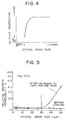
- Fig. 4 shows a conceptual diagram showing the above-mentioned fact. As is apparent from Fig. 4, the austenite crystal grain sizes and the Ms point temperature are in a close relationship to each other and the Ms point temperature is abruptly lowered at a specific crystal grain size.
- Fig. 5 shows changes in the relative magnetic permeability ⁇ of metallic member before cooling and after cooling to and having retained at -40°C for one hour.
- the present inventors have found for the first time that the relative magnetic permeability ⁇ will not exceed 1.2 even by keeping the metallic members at -40°C by selecting heating conditions so that the austenite crystal grain size can be kept not more than 30 ⁇ m.
- the present inventors have furthermore studied an optimum process for making the crystal grain size of austenite part (non-magnetized part) of the metallic member not more than 30 ⁇ m, and have found that the optimum process comprises subjecting the metallic member to a cold working, thereby ferromagnetizing the member and then to solid-solution treatment within 10 seconds. That is, the heating of the member must be carried out for a very short time. That is, an increase in the grain size in the region of the member, where the martensite structure is transformed to the austenite structure, can be prevented by conducting the solid-solution treatment within 10 seconds. To this effect, specifically it is desirable to use a high frequency heating in the solid-solution treatment.
- Fig. 5 shows a relationship between crystal grain size in the non-magnetized region obtained by local solid-solution treatment of the ferromagnetized part by high frequency heating and changes in the relative magnetic permeability ⁇ after cooling to and having retaining the non-magnetized region at -40°C.
- the relative magnetic permeability ⁇ will not exceed 1.2 even after having retained the non-magnetized region at -40°C by selecting the heating conditions so that the crystal grain size can be kept not more than 30 ⁇ m.
- the present inventors have found the desired conditions for metallic members applicable to desired composite magnetic members, as mentioned above, but have not yet found a fully satisfactory process for producing desired composite magnetic member.
- the present inventors tried to make cup-shaped members 10 shown in Fig. 10C by the conventional continuous press drawing work, but have found that the magnetic flux density B 4000 of not less than 0.3T, as desired in the present invention, could not constantly be obtained only by conducting such a continuous press drawing work.
- the present inventors have found the following fact as a failure to obtain the desired magnetic flux density B 4000 .
- Fig. 6 shows a relationship between a degree of working in working steps and a working temperature of the metallic member under plastic working.
- the working temperature of the member under plastic working will readily reach the Md point, a limit temperature for the transformation of austenite structure showing non-magnetic properties to martensite structure showing ferromagnetic properties due to heat generation during the plastic working.
- the present inventors have found that the further working over a point X corresponding to the Md point will be an over-working ⁇ that gives a strain no more contributing to the generation of martensite structure, and thus working only up to the point X can give an effective strain, though the over working ⁇ has a possibility for ferromagnetization.
- the present inventors have conceived that the above-mentioned problem can be solved by giving a strain divisionally, thereby suppressing or reducing the heat generation during the working to a minimum, and that further ferromagnetization can be attained by cooling the member to not more than the room temperature to remove the heat generated during the divisional plastic working in advance to succeeding divisional working step and then conducting the succeeding plastic working step to give a strain to the member.
- Fig. 6 the plastic working shown by zigzag line B is conducted by dividing the conventional one working step to three stages 1 ⁇ , 2 ⁇ and 3 ⁇ .
- the plastic working can be performed to the desired final degree of working while maintaining the working temperature below the Md point and thus a satisfactory ferromagnetic property can be given to the member.
- the plastic working to give a strain can be carried out after cooling the member in advance.
- the working temperature of the member can be kept lower than the Md point even at the final degree of working, as shown by line C in Fig. 6, and the ferromagnetization level of the member, for example, B 4000 , can be readily made not less than 0.3T thereby. That is, the member is cooled to an extremely low temperature such as down to -196°C to improve the ferromagnetization level and remove the heat generated during the plastic working.
- the target ferromagnetization level such as a magnetic flux density B 4000 of not less than 0.3T can be attained without any increased number of working stages, that is, with a higher working efficiency.
- the working temperature of the member at the individual working stages should be not more than 100°C for the following reasons.
- Fig. 7 shows a relationship between a working temperature of metallic member and a martensite proportion (%).
- the present inventors investigated a relationship between a strain-giving rate and an increase in the working temperature of the member by tension tests. Then, the present inventors conducted a tension test of metastable austenite stainless steel in a thermostat tank at a strain-giving rate of 1 mm/min at which the heat generation due to the plastic working could be disregarded. As a result, it was found that the martensite structure was no more generated at 100°C or higher, as shown in Fig. 7. That is, the proportion of generated martensite structure is 10% or less at 100°C or higher. Thus, the desired magnetic characteristics could be obtained by using a working temperature of not more than 100°C in the plastic working of the member.
- the present inventors have made further studies and have found that stress corrosion cracking can be prevented by applying an ironing work of 10% or more to the metallic member after the drawing work.
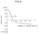
- Fig. 8 shows a relationship between a degree of ironing work and changes in residual stress.
- Main factor for causing stress corrosion crackings is said to be a residual tensile stress occurring along the circumferential direction (see Fig. 9), generated by the drawing work, and the residual tensile stress can be considerably reduced by the ironing work.
- the residual stress can enter into a region causing no more residual stress cracking at a degree of ironing work of 10%, and can be completely changed in a residual compression strain, contrary to expectation, at a degree of ironing work of 20% or more.
- Samples of ironed member were evaluated by dipping in an aqueous 42% magnesium chloride solution. It was found by this test that no stress corrosion cracking occurred on the samples subjected to ironing work with a degree of ironing work of 10% or more as shown in Table 1.
- the ironing work is also a very effective means for giving a strain to attain ferromagnetization, and thus is one of steps for ferromagnetization.
- Degree of ironing 0 5 10 20 30 40 50 Stress corrosion cracking occurred occurred non non non non non non non
- a composite magnetic member which comprises a metallic member comprising not more than 0.6% C, 12 to 19% Cr, 6 to 12% Ni, not more than 2% Mn, not more than 2% Mo, not more than 1% Nb, and the balance being Fe and inevitable impurities, where
- a stress relieving annealing is a treatment to improve the magnetic characteristics by removing plastic strains given to the member by cold working.
- a process for producing a composite magnetic member which comprises ferromagnetizing a metallic member comprising not more than 0.6% C, 12 to 19% Cr, 6 to 12% Ni, not more than 2% Mn, not more than 2% Mo, not more than 1% Nb, and the balance being Fe and inevitable impurities, where
- a process for producing a composite magnetic member which comprises subjecting a metallic member comprising not more than 0 6% C, 12 to 19% Cr, 6 to 12% Ni, not more than 2% Mn, not more than 2% Mo, not more than 1% Nb, and the balance being Fe and inevitable impurities, where
- a process for producing a composite magnetic member which comprises subjecting a metallic member comprising not more than 0.6% C, 12 to 19% Cr, 6 to 12% Ni, not more than 2% Mn, not more than 2% Mo, not more than 1% Nb, and the balance being Fe and inevitable impurities, where
- a process for producing a composite magnetic member which comprises cooling a metallic member comprising not more than 0.6% C, 12 to 19% Cr, 6 to 12% Ni, not more than 2% Mn, not more than 2% Mo, not more than 1% Nb, and the balance being Fe and inevitable impurities, where
- a process for producing a composite magnetic member which comprises subjecting a metallic member comprising not more than 0.6% C, 12 to 19% Cr, 6 to 12% Ni, not more than 2% Mn, not more than 2% Mo, not more than 1% Nb, and the balance being Fe and inevitable impurities, where
- an electromagnetic valve which comprises a movable iron core provided slidably in a magnetic circuit formed by excitation of a coil, the movable iron core being to open or shut a fluid passage by sliding caused by the excitation of the coil, and a support member with a slide hole through which the movable iron core is inserted slidably, at least one part of the support member being provided in the magnetic circuit, the support member being made from a metallic member comprising at least one ferromagnetized part and at least one non-magnetized part, as continuously and integrally formed, the non-magnetized part having a span of not less than 1 mm wide.
- an electromagnetic valve which comprises a movable iron core provided slidably in a magnetic circuit formed by excitation of a coil, the movable iron core being to open or shut a fluid passage by sliding caused by the excitation of the coil, and a support member with a hole through which the movable iron core is inserted slidably, at least one part of the support member being provided in the magnetic circuit, the support member being made from a metallic member comprising at least one ferromagnetized part and at least one non-magnetized part, as continuously and integrally formed, and the non-magnetized part surrounding at least the lower end of the movable iron core.
- a remarkable composite magnetic member whose non-magnetized part is never converted to a ferromagnetized part, even when exposed to a severe temperature condition, can be provided on the basis of the novel findings shown in Figs. 1 to 5.
- a composite magnetic member having at least one ferromagnetized part and at least one non-magnetized part, as continuously and integrally formed can be produced quite easily, on the basis of the novel findings shown in Figs. 1 to 8.
- a support member having at least one ferromagnetized part and at least one non-magnetized part, as continuously and integrally formed is used in an electromagnetic valve and a movable iron core can be stably driven by using the non-magnetized part having a span of not less than 1 mm wide.
- the support member whose non-magnetized part is made to surround the lower end of the movable iron core, is provided and thus the movable iron core can be more stably driven.
- Degree of ferromagnetization by martensitization of austenite structure largely depends not only on the degree of working, but also on the working temperature, and further ferromagnetization can be attained by controlling the working temperature.
- a high frequency coil 22 was provided to surround the middle part of the ferromagnetized cylinder 20, as shown in Fig. 11A, and part of the cylinder 20 was locally heated and cooled by a cooling liquid at a temperature of about 20°C, thereby non-magnetizing the part.
- the following high frequency heating conditions were employed:
- the high frequency heating was employed as a heating means for non-magnetizing part of the cylinder 20 on the following grounds:
- part of martensite region has been subjected to local solid-solution treatment to convert it to an austenite region (non-magnetized region).
- a high energy beam such as a laser, an electron beam, etc. has been used.
- the crystal grains having strains due to cold working have been once melted by hitting the surface of the ferromagnetized region with a high energy beam and immediately cooled to form a solidification structure, thereby non-magnetizing the ferromagnetized region.
- the non-magnetized region has a desired relative magnetic permeability ⁇ of not more than 1.2 because of generation of ⁇ ferrite peculiar to the solidification structure and enlarged crystal grains in the heat-influenced region near the molten part by the high energy beam, etc.
- ⁇ ferrite peculiar to the solidification structure and enlarged crystal grains in the heat-influenced region near the molten part by the high energy beam, etc.
- high frequency heating is employed in the present invention.
- the high frequency heating uses an eddy current locally, generated in the member by high frequency current as a heating source, not only solid-solution treatment can be carried out very simply within a short time without any local melting by properly controlling the coil shape, frequency, current voltage, etc., but also crystal grain size can be prevented from enlargement because of a short heating time such as a few seconds.
- the cylinder 20 was magnetically sectioned into, for example, three regions A, B and C, as shown in Fig. 11B, by the above-mentioned local high frequency heating and cooling, where the regions A and C had ferromagnetic characteristics, whereas the region B therebetween had non-magnetic characteristics.
- Test pieces for determining magnetic characteristics were sampled from the ferromagnetized regions A and C and also from the non-magnetized region B of the thus obtained cylinders of Examples 1 to 4, and subjected to determination of magnetic characteristics by a DC magnetic fluxmeter or by a permeameter.
- the results are shown in the following Table 3, and it was found that composite magnetic members having desired magnetic characteristics and crystal grain sizes of not more than 30 ⁇ m as conditions for retaining the non-magnetic property at an extremely low temperature were obtained thereby.
- Example 5 stress relieving annealing was further carried out at 500°C or temperatures below 500°C on the cylinder 20 of Example 2 after the above-mentioned cold working to attain further ferromagnetization.
- Fig. 12 shows changes in the magnetic characteristics of the cylinder of Example 2, when the cylinder was subjected to stress relieving annealing at 500°C or temperatures below 500°C.
- the magnetic characteristics can be increased with increasing annealing temperature and the maximum magnetic characteristics can be obtained at 450°C with air cooling.
- Examples 1 to 4 show an example of cup-shaped members, but the present invention is not limited thereto. That is, a pipe-shaped member is made from the present metallic member composition for the present composite magnetic member and ferromagnetized by cold working such as drawing, etc., and the resulting ferromagnetized member can be locally non-magnetized by high frequency heating, or a plate-shaped member is prepared from the present metallic member composition for the present composite magnetic member, ferromagnetized by cold working such as rolling, etc., and the resulting ferromagnetized member can be locally non-magnetized by high frequency heating.
- Example 5 maximum magnetic characteristics could be obtained at an annealing temperature of 450°C, but the present invention is not limited thereto. That is, when the metallic member composition and cold working conditions are changed, an annealing temperature capable of obtaining optimum magnetic characteristics will change in a temperature range of not more 500°C.
- the disk plates 1 of alloys of Examples 6 to 9 thus prepared were subjected to stagewise drawing work at room temperature through the shape, as shown in Fig. 13B, to obtain cup shapes 15, as shown in Fig. 13C.
- the stagewise drawing of the disk plates 1 was carried out at 7 stages to prevent an increase in the working temperature and obtain a good ferromagnetic property, while keeping the working temperature of the disk plates 1 below 100°C, thereby obtaining the cup-shapes 15. Then, by further ironing works through shapes, as shown in Figs.
- Degree of ferromagnetization by martensitization of austenite structure largely depends not only on the degree of working, but also on the working temperature, and further ferromagnetization can be attained by controlling the working temperature.
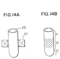
- a high frequency coil 27 was provided to surround the middle part of the ferromagnetized cylinder 25, as shown in Fig. 14A, and part of the cylinder 25 was locally heated and cooled by a cooling liquid at a temperature of about 20°C, thereby non-magnetizing the part.
- the following high frequency heating conditions were employed:
- the high frequency heating uses an eddy current locally generated in the member by high frequency current as a heating source, not only solid-solution treatment can be carried out very simply within a short time without any local melting by properly controlling the coil shape, frequency, current voltage, etc., but also crystal grain size can be prevented from enlargement because of a short heating time such as a few seconds.
- the cylinder 25 was magnetically sectioned into, for example, three regions A, B and C, as shown in Fig. 14B, by the above-mentioned local high frequency heating and cooling, where the regions A and C had ferromagnetic characteristics, whereas the region B therebetween had non-magnetic characteristics.
- Test pieces for determining magnetic characteristics were sampled from the ferromagnetized regions A and C and also from the non-magnetized region B of the thus obtained cylinders of Examples 6 to 13, and subjected to determination of magnetic characteristics by a DC magnetic fluxmeter or by a permeameter.
- the results are shown in the following Table 5, and it was found that compound magnetic members having desired magnetic characteristics and crystal grain sizes of not more than 30 ⁇ m as conditions for retaining the non-magnetic property at an extremely low temperature could be obtained.
- Example 14 and 15 cooling was conducted before giving a strain to the alloy.
- the alloy used in these Examples 14 and 15 was the alloy having the same composition as that of Example 6.
- the alloy of the same composition as in Example 6 was melted in a vacuum induction furnace and formed into disk plates 1, 1.2 mm thick, as shown in Fig. 13A, by casting and rolling, and the disk plates 1 were annealed to a softened state by heating at 950°C.
- Example 14 The thus prepared disk plates were cooled to -77°C by dipping the disk plates into a liquid methanol cooled to -77°C by adding thereto dry ice in Example 14, whereas the other disk plates were cooled to -196°C by dipping the disk plates into a liquefied nitrogen in Example 15.
- Example Cooling Magnetic flux density of ferromagnetized region B 4000 (T) Relative magnetic permeability of non-magnetized region ⁇ Crystal grain size of non-magnetized region ⁇ m 14 to -77 0.92 1.10 3 15 to -196 1.18 1.09 3
- composite magnetic members having a ferromagnetic property can be obtained by cooling the alloy before the drawing, and composite magnetic members having at least one satisfactorily ferromagnetized part and at least one satisfactorily non-magnetized part, as continuously and integrally formed, can be obtained with less working steps by cooling before the strain-giving working.
- Fig. 15 is a vertical cross-sectional view of an electromagnetic valve for closing an oil-hydraulic line, using the present composite magnetic member.
- An electromagnetic valve 30 is provided with a cup-shaped sleeve 32 with a ferromagnetized part 32a and a non-magnetized part 32b as continuously and integrally formed by cold working and high frequency heating of alloy of Example 1 as a support member, coaxially with a coil 31.
- the sleeve is hermetically bonded to a stator 33 as a ferromagnetic core by bonding such as welding, etc. so as to prevent any leakage of an oil-hydraulic fluid.
- a plunger 34 as a slidable, movable iron core is inserted into the sleeve 32, and the plunger 34 is hermetically fixed to an upper end of a shaft 35, whereas a ball 36 is fixed to the lower end of the shaft 35.
- An insertion hole 37 is formed in the stator 33 in the axial direction so that the shaft 35 can slidably move through the insertion hole 37.
- outflow openings 50 are provided in the radial direction and a seat valve 38 is inserted into the insertion hole 37.
- a hole 54 communicating an inflow opening 52 with the outflow openings 50 is provided through the seat valve 38.
- a valve seat 56 is formed on the top end of the seat valve 38.
- a spring 39 is provided between the seat valve 38 and the shaft 35 against the valve seat 56 to give an expansion force to the shaft 35 in the direction to depart the ball 36 from the valve seat 56.
- a ferromagnetic yoke 40 is provided in contact with the stator 33 and the sleeve 32 so as to cover the outer periphery of the coil 31.
- the shaft 35 and the plunger 34 are pressed to the top end of the sleeve 32 by the expansion force exerted by the spring 39, and the ball 36 is departed from the valve seat 56 thereby.
- the inflow opening 52 are communicated with the outflow openings 50 through the communication hole 54 to open the valve, and the oil-hydraulic fluid is passed from the inflow opening 52 to the outflow openings 50.
- excitation of the coil 31 is made to take place by passing an electric current through the coil 31 and a magnetic circuit is generated in the direction of yoke 40 ⁇ ferromagnetized part 32a of the sleeve 32 ⁇ plunger 34 ⁇ stator 33, as shown by excitation route L as the magnetic circuit, whereby the plunger 34 is attracted downwards in the axial direction to push the shaft 35 to slide through the insertion hole 37. Then, the ball 36 is set onto the valve seat 56 to shut off communication of the inflow opening 52 with the outflow openings 50 and close the valve.
- the sleeve 32 will be explained in detail below.
- the sleeve 32 is ferromagnetized throughout by drawing work and ironing work and then locally non-magnetized in a desired region by high frequency heating, as described in Examples 1 to 4. Position and span or width of the non-magnetized region give a large influence on the magnetic force acting on the plunger 34. That is, the electromagnetic valve of this Example is formed so that a clearance 60 is provided between the plunger 34 and the stator 33 within the axial length of the coil 31. By providing the clearance 60 within the axial length of the coil 31, a decrease in the magnetic force due to leakage of magnetic flux can be prevented when an electric current is applied to the coil 31.
- the span or width of the non-magnetized part 32b formed in the sleeve 32 also contributes to prevent a decrease in the magnetic force.
- Fig. 16 shows a relationship between a span or width of non-magnetized part 32b and a magnetic force.
- the magnetic force is abruptly lowered when the span or width of the non-magnetized part 32b is less than 1 mm, and thus the lower limit width must be 1 mm.
- the upper limit width of the non-magnetized part 32b is set to an l/L ratio of not more than 0.95, where L is the axial length of sleeve 32 and l is the axial length of non-magnetized part 32b, a sufficiently satisfied magnetic force can be obtained, because when the width of non-magnetized part 32b is less than 1 mm, a relative magnetic permeability ⁇ at the clearance 60 is smaller than that of non-magnetized part 32b of the sleeve 32, and consequently the magnetic circuit that goes through the clearance 60 will go around the non-magnetized part 32b of the sleeve 32, and the magnetic force onto the plunger 34 will be lowered.
- the width of the ferromagnetized part 32a will be smaller and consequently the magnetic flux that generates a magnetic circuit will be saturated, and the magnetic force will be also lowered.
- the top end part of sleeve 32 was ferromagnetized, and thus when an electric current was passed through a coil 31, the generated magnetic flux went not only along the side surface of the sleeve 32, as shown in Fig. 15, but also went around the top end part. Thus, the magnetic force was lowered.
- the sleeve 32 was formed by cold working the top end part of the sleeve 32 at a lower degree of plastic deformation than that of the side surface of the sleeve 32, and thus a lower stress was applied to the top end part of the sleeve 32, thereby lowering the ferromagnetization level at the top end part, as compared with that along the side surface.
- two ferromagnetized parts having different ferromagnetization levels could be formed on the same sleeve 32, and thus when the upper end of plunger 34 was made to contact the inside periphery at the top end part of the sleeve 32 in a point or line contact state, the magnetic flux no more went around the top end part of the sleeve 32.
- uniform and sufficient ferromagnetic characteristics were obtained at the site where such characteristics were required, and the ferromagnetic characteristics could be suppressed to a lower level at the site where not required.
- the magnetic flux density B 4000 was made to be not less than 0.3T as the ferromagnetization level on the side surface of the sleeve, whereby the magnetic force could be stabilized.
- non-magnetized part 32b was locally formed on the sleeve 32 by conducting local high frequency heating to the part desired to be non-magnetized from the outside or the inside of the sleeve 32, thereby uniformly conducting solid-solution treatment of the desired part on all the outer and inner peripheral sides at the same time.
- the high frequency-heated part of sleeve 32 could be completely and uniformly non-magnetized with a better dimensional precision.
- the magnetic flux could be effectively generated by passing an electric current through the coil 31, while considerably reducing the magnetic resistance at the ferromagnetized part 32a of sleeve 32, contributing to efficient driving of plunger 34.
- the magnetic force could be increased by about 40% over that of the conventional sleeve having only the non-magnetized part. That is, the amount of coil could be reduced, corresponding to the 40% increase in the magnetic force, and the electromagnetic valve could be made considerably smaller in the size.
- Fig. 18 is a vertical cross-sectional view of another electromagnetic valve for opening or closing, for example, an oil hydraulic line, using the present composite magnetic member, where identical members to those of Fig. 15 are identified with the identical numerals.
- the electromagnetic valve shown in Fig. 18 has also a sleeve 32 with two ferromagnetized parts 32a and one non-magnetized part 32b coaxially with a coil 31, and the sleeve 32 is inserted into an hole 33a of a stator 33 as a ferromagnetic core and hermetically bonded to the stator 33 by bonding such as welding, etc. so as to prevent any leakage of an oil-hydraulic fluid.
- a ferromagnetic stopper 70 is hermetically fixed to the inside top end of sleeve 32 by a hermetically fixing means such as welding, caulking, etc.
- a slidable ferromagnetic plunger 74 is inserted into the sleeve 32, as separated by a non-magnetic plate 72.
- the plunger 74 is fixed to the upper end part of a shaft 35 at a given distance from the top of end of the plunger 74 to provide a hollow space 84 and a ball 36 is fixed to the lower end of the shaft 35.
- An insertion hole 37 through which the shaft 35 can slidably move is formed through the stator 33 in the axial direction.
- Inflow openings 76 are provided through the stator 33 at the ball 36-fixing end, i.e. lower end, of the shaft 35, and a seat valve 38 with a valve seat 82 is inserted into an outflow opening 78 at a contacting position with the ball 36, and a hole 80 that communicates the inflow openings 76 with the outflow opening 78 is provided through the seat valve 38 in the axial direction.
- a spring 86 is provided between the lower end of the stopper 70 and the upper end of the shaft 35 to exert an expansion force so that the fixed assembly of the plunger 74 and the shaft 35 can move downwards to put the ball 36 onto the valve seat 82.
- a ferromagnetic yoke 88 is provided in contact with the stator 33 and the sleeve 32 to cover the outer periphery of a coil 31.
- Example 17 the present composite magnetic member comprising two ferromagnetized parts 32a and one non-magnetized part 32b, as continuously and integrally formed, was employed as the sleeve 32, and the shaft 35 could be driven under a severe temperature condition without any change in the-magnetic characteristics.
- Example 17 the present composite magnetic member is used in an electromagnetic valve for controlling the oil hydraulic line.
- the present electromagnetic valve is not limited to electromagnetic valves for controlling the oil hydraulic line, but the present compound magnetic member can be employed, for example, in electromagnetic valves for use in injectors, etc. and in those for controlling a flow rate of a gas, etc.
- a metallic comprising not more than 0.6% C, 12 to 19% Cr, 6 to 12% Ni, not more than 2% Mn, not more than 2% Mo, not more than 1% Nb and the balance being Fe and inevitable impurities, where
Abstract

Description
- The present invention relates to a composite magnetic member comprising at least one non-magnetized part and at least one ferromagnetized part, both parts being continuously and integrally formed, a process for producing the member and an electromagnetic valve using the member, and particularly to a composite magnetic member capable of fully maintaining ferromagnetic and non-magnetic characteristics against changes in temperature, process for producing the member and an electromagnetic valve using the member.
- In generating a magnetic circuit in products such as electromagnetic valves, etc. by discretely providing a ferromagnetic part and a non-magnetic part in one product, it is necessary to make a mild steel part from a ferromagnetic material and an austenitic stainless steel part from a non-magnetic material individually, then assemble these ferromagnetic part and the non-magnetic part together while joining the parts properly by bonding, for example, by soldering, to make a member for the magnetic circuit. However, in making a member for the magnetic circuit in this manner, it is necessary to make a plurality of parts from a ferromagnetic material and a plurality of parts from a non-magnetic material individually and assemble such a plurality of the parts, while joining them by bonding. Thus, many steps and much labor are required for making such a member, complicating the procedure.
- It is known that ordinary austenite stainless steel, high manganese steel, etc. are in a non-magnetic state after solid-solution treatment, but can be given a ferromagnetic property by cold working at room temperature to induce and generate a martensite structure. However, the degree of ferromagnetization obtained by this procedure is not high and thus it is actually difficult to apply this procedure to production of members for the magnetic circuit.
- It is also possible as a means for locally non-magnetizing part of a ferromagnetic material such as mild steel, etc. to diffuse an austenitizing element such as Mn, Cr, Ni, etc. into the ferromagnetic material from the surface, but such a means still has a problem in the production of members for the magnetic circuit.
- JP-A-63-161146 discloses materials utilizable as a magnetic scale by optimizing the composition of austenite stainless steel or high manganese steel and working procedures for such materials to make members having both ferromagnetic and non-magnetic properties at the same time, where metastable austenite stainless steel is cold drawn into wires, thereby ferromagnetizing the austenite stainless steel based on martensitizing of austenite structure and part of the martensitized wires are further subjected to a local solid-solution treatment to locally non-magnetize the martensitized wires on the basis of local back-austenitization. Members having both ferromagnetic and non-magnetic properties at the same time can be obtained thereby. In this case, the composite magnetic members disclosed in JP-A-63-161146 can have a satisfactorily ferromagnetized part and a satisfactorily non-magnetized part, as integrated together, which can work satisfactorily under the ordinary circumstance, but no measures have been taken against temperatures at which the non-magnetized parts are to be served. That is, under a severe temperature circumstance such as an extremely low temperature circumstance, a martensite structure is generated on the non-magnetized part, thereby transforming the non-magnetic properties to ferromagnetic properties. This has been a problem.
- Currently available electromagnetic valves work as follows: a magnetic circuit is generated by passing an electric current through a coil in the valve, and a plunger is actuated through a sleeve undergoing magnetic working by the generated magnetic circuit. Particularly when an electromagnetic valve is used for oil-hydraulic control, the plunger must slide oil-tight along the inside surface of the sleeve. The conventional sleeve is made from a non-magnetic material, and to make the plunger behavior more sensitive, the magnetic circuit must be permeated through the non-magnetic material, and thus the force of excitation of the coil itself must be increased. Still furthermore, it is possible to ferromagnetize only part of the sleeve through which the magnetic circuit is to permeate. In the sleeve structure made by integrating a plurality of parts by bonding, the bonding must be carried out by soldering, welding, or the like to make the sleeve, and thus considerable post-working is required for obtaining desired dimension, shape and precision. Thus, there is a post-working problem.
- An object of the present invention is to provide a composite magnetic member comprising at least one satisfactorily ferromagnetized part and at least one satisfactorily non-magnetized part, both parts being continuously and integrally formed, which can work under a severe circumstance such as an extremely low temperature circumstance; a process for producing the member; and an electromagnetic member using the member.
- At first, the present inventors have carefully checked what physical characteristics are desirable for an composite magnetic member having satisfactory ferromagnetic and non-magnetic characteristics at the same time under the ordinary circumstance, and have found that a composite magnetic member is required to comprise a non-magnetized part having a relative magnetic permeability µ of not more than 1.2 and the remaining ferromagnetized part having a magnetic flux density B50 of not less than 0.3T at the same time except the transition region between the non-magnetized part and the ferromagnetized part and except parts particularly not required for the ferromagnetic characteristics.
- To satisfy the above-mentioned requirements, the present inventors have selected the following composition which can generate a stable austenite structure at room temperature and also generate a martensite structure by cold working to make the cold worked parts ferromagnetic and can give satisfactory magnetic characteristics.
- A metallic member that can meet the above-mentioned requirements has a composition which comprises not more than 0.6% C, 12 to 19% Cr, 6 to 12% Ni, not more than 2% Mn, not more than 2% Mo, not more than 1% Nb, and the balance being Fe and inevitable impurities, where it is desirable that:
- Hirayama's equivalent H eq = [Ni %] + 1.05 [Mn %] + 0.65 [Cr %] + 0.35 [Si %] + 12.6 [C %] is 20 to 23%;
- Nickel equivalent Ni eq = [Ni %] + 30 [C %] + 0.5 [Mn %] is 9 to 12%, and
- Chromium equivalent Cr eq = [Cr %] + (Mo %] + 1.5 [Si %] + 0.5 [Nb %] is 16 to 19%, wherein % is and will be hereinafter by weight.
-
- As to Hirayama's equivalent, reference is made to Nihon Kinzoku Gakkaishi (Journal of the Society of Metallurgy of Japan), 34 No. 5, 507-510 (1970); 34 No. 8, 826-829 (1970); 34 No. 8, 830-835 (1970); 35 No. 5, 447-451 (1971).
- Why the C content is selected to be not more than 0.6% in the above-mentioned composition of the metallic member, shapability by working will be lowered with increasing carbide content, though the magnetic characteristics can be satisfied over 0.6% C. Why the Cr content is selected to be 12 to 19% and the Ni content to be 6 to 12%, non-magnetic properties, for example, a relative magnetic permeability µ of not more than 1.2, cannot be obtained below the lower limit Cr and Ni contents, whereas above the higher limit Cr and Ni contents, B4000, a magnetic flux density when the intensity of magnetic field is 3.980 A/m, cannot be made less than 0.3T (0.3 tesla). When the Mn content is over 2%, the shapability by working is lowered. Thus, the upper limit Mn content is selected to be 2%.
- Furthermore, specific amounts of Mo and Nb can be-contained in the metallic member. Mo, when contained, can effectively lower a Ms point, and Nb, when contained, can effectively contribute to an increase in the strength of the metallic member. Mo or Nb or both Mo and Nb can be contained, depending on the desired purpose. It is preferable that the metallic member contains not more than 2% Mo and not more than 1% Nb. Above these upper limit contents the shapability by working will be lowered.
- Limitation of the respective elements to the above-mentioned ranges is still not satisfactory, and it is necessary that desired magnetic characteristics can be obtained by combinations within these combination ranges. To this effect, Hirayama's equivalent H eq = 20-23%, nickel equivalent Ni eq = 9-12% and chromium equivalent Cr eq = 16-19% must be satisfied in the present invention. Unless these conditions are not satisfied, only one of desired ferromagnetic characteristics and desired non-magnetic characteristics is satisfied.
- Grounds for specifying these conditions will be explained below:
- Fig. 1 shows a relationship between a Hirayama's equivalent and a relative magnetic permeability.
- As is apparent from Fig. 1, a relative magnetic permeability µ is lowered with increasing Hirayama's equivalent H eq, and when an Hirayama's equivalent H eq is not less than 20%, a relative magnetic permeability µ of not more than 1.2 can be satisfied. Thus, the lower limit to the Hirayama's equivalent H eq is selected to be 20%.
- Fig. 2 shows a relationship between a draft percentage at cold working and a magnetic flux density B4000 after the cold working.
- As is apparent from Fig. 2, the austenite structure is stabilized with increasing Hirayama's equivalent H eq, and as a result ferromagnetization by cold working is hard to take place and the magnetic flux density B4000 is lowered. At the cold rolling as cold working, B4000 = 0.3T was hard to obtain over H eq = 23%, even if the draft percentage was increased. Thus, the upper limit to Hirayama's equivalent H eq is selected to be 23% in the present invention.
- A nickel equivalent Ni eq and a chromium equivalent Cr eq are selected to be 9-12% and 16-19%, respectively, on the same grounds as above
- Usually not more than 2% Si and not more than 0.5% Al as deoxidizing elements and other inevitable impurity elements are contained in the metallic member, but these elements will not give any adverse effect on the characteristics of the composite magnetic member, when produced.
- The present inventors have further found that the metallic member having the above-mentioned composition had not satisfactory magnetic characteristics under a severe temperature circumstance, and have made a further extensive study. That is, the present inventors made metallic members satisfying the above-mentioned conditions for the composition and subjected the members to solid-solution treatment to non-magnetize them, and then left them to stand at various low temperatures. As shown in Fig. 3, an increase in the relative magnetic permeability was observed in the members and the requirements of µ = not more than 1.2 as the non-magnetic characteristics were not satisfied.
- Thus, it has been found further necessary that the metallic members having the above-mentioned composition satisfy the requirements for ferromagnetic and non-magnetic characteristics at the same time and undergo no change in the relative magnetic permeability µ of the non-magnetized part even under a severe temperature circumstance.
- As a result of further extensive studies, the present inventors have found metal member structures without any change in the relative magnetic permeability µ even at an extremely low temperature, such as a temperature as low as -40°C. That is, the present inventors have found that an increase in the relative magnetic permeability µ at an extremely low temperature is due to a fact that the extremely low temperature is lower than an Ms point temperature, i.e. a temperature that initiates to transform the austenite structure to the martensite structure, and have conceived that an increase in the relative magnetic permeability at a temperature as low as -40°C can be suppressed by making the Ms point temperatures of the metallic members having the above-mentioned composition lower than, for example, -40°C.
- Thus, the present invention is characterized by changing grain sizes of austenite crystal grains to make the Ms point temperature lower than the conventional Ms point temperature, thereby suppressing changing of the non-magnetic characteristics to the ferromagnetic characteristics in an extremely low temperature circumstance. That is, it is the present invention that has applied to the composite magnetic members for the first time such a fact that the Ms point temperature that initiates to transform the austenite structure to the martensite structure is lowered with decreasing austenite crystal grain sizes.
- Fig. 4 shows a conceptual diagram showing the above-mentioned fact. As is apparent from Fig. 4, the austenite crystal grain sizes and the Ms point temperature are in a close relationship to each other and the Ms point temperature is abruptly lowered at a specific crystal grain size.
- Fig. 5 shows changes in the relative magnetic permeability µ of metallic member before cooling and after cooling to and having retained at -40°C for one hour. As is apparent from Fig. 5, the present inventors have found for the first time that the relative magnetic permeability µ will not exceed 1.2 even by keeping the metallic members at -40°C by selecting heating conditions so that the austenite crystal grain size can be kept not more than 30 µm.
- The present inventors have furthermore studied an optimum process for making the crystal grain size of austenite part (non-magnetized part) of the metallic member not more than 30 µm, and have found that the optimum process comprises subjecting the metallic member to a cold working, thereby ferromagnetizing the member and then to solid-solution treatment within 10 seconds. That is, the heating of the member must be carried out for a very short time. That is, an increase in the grain size in the region of the member, where the martensite structure is transformed to the austenite structure, can be prevented by conducting the solid-solution treatment within 10 seconds. To this effect, specifically it is desirable to use a high frequency heating in the solid-solution treatment.
- Fig. 5 will be explained in more detail below. That is, Fig. 5 shows a relationship between crystal grain size in the non-magnetized region obtained by local solid-solution treatment of the ferromagnetized part by high frequency heating and changes in the relative magnetic permeability µ after cooling to and having retaining the non-magnetized region at -40°C. As already mentioned above, it has been found that the relative magnetic permeability µ will not exceed 1.2 even after having retained the non-magnetized region at -40°C by selecting the heating conditions so that the crystal grain size can be kept not more than 30 µm.
- The present inventors have found the desired conditions for metallic members applicable to desired composite magnetic members, as mentioned above, but have not yet found a fully satisfactory process for producing desired composite magnetic member. For example, the present inventors tried to make cup-shaped
members 10 shown in Fig. 10C by the conventional continuous press drawing work, but have found that the magnetic flux density B4000 of not less than 0.3T, as desired in the present invention, could not constantly be obtained only by conducting such a continuous press drawing work. As a result of further investigations, the present inventors have found the following fact as a failure to obtain the desired magnetic flux density B4000. - Explanation will be made, referring to Fig. 6, which shows a relationship between a degree of working in working steps and a working temperature of the metallic member under plastic working.
- Once a strain is given to the metallic member, the working temperature of the member under plastic working will readily reach the Md point, a limit temperature for the transformation of austenite structure showing non-magnetic properties to martensite structure showing ferromagnetic properties due to heat generation during the plastic working. The present inventors have found that the further working over a point X corresponding to the Md point will be an over-working α that gives a strain no more contributing to the generation of martensite structure, and thus working only up to the point X can give an effective strain, though the over working α has a possibility for ferromagnetization.
- Thus, the present inventors have conceived that the above-mentioned problem can be solved by giving a strain divisionally, thereby suppressing or reducing the heat generation during the working to a minimum, and that further ferromagnetization can be attained by cooling the member to not more than the room temperature to remove the heat generated during the divisional plastic working in advance to succeeding divisional working step and then conducting the succeeding plastic working step to give a strain to the member.
- That is, by conducting the plastic working such as drawing and ironing in a divisional manner, for example, at as many stages as possible, to obtain a metastable austenite stainless steel structure, it can be optimized to give a strain in the plastic working, as shown by a zigzag line B in Fig. 6, and the heat generation due to the plastic working can be suppressed thereby.
- In Fig. 6, the plastic working shown by zigzag line B is conducted by dividing the conventional one working step to three stages 1 ○ , 2 ○ and 3 ○ .
- By conducting the plastic working at a plurality of stages in this manner, the plastic working can be performed to the desired final degree of working while maintaining the working temperature below the Md point and thus a satisfactory ferromagnetic property can be given to the member.
- Furthermore, the plastic working to give a strain can be carried out after cooling the member in advance. By cooling the member in advance, the working temperature of the member can be kept lower than the Md point even at the final degree of working, as shown by line C in Fig. 6, and the ferromagnetization level of the member, for example, B4000, can be readily made not less than 0.3T thereby. That is, the member is cooled to an extremely low temperature such as down to -196°C to improve the ferromagnetization level and remove the heat generated during the plastic working. By this cooling treatment, the target ferromagnetization level such as a magnetic flux density B4000 of not less than 0.3T can be attained without any increased number of working stages, that is, with a higher working efficiency. The working temperature of the member at the individual working stages should be not more than 100°C for the following reasons.
- Fig. 7 shows a relationship between a working temperature of metallic member and a martensite proportion (%).
- The present inventors investigated a relationship between a strain-giving rate and an increase in the working temperature of the member by tension tests. Then, the present inventors conducted a tension test of metastable austenite stainless steel in a thermostat tank at a strain-giving rate of 1 mm/min at which the heat generation due to the plastic working could be disregarded. As a result, it was found that the martensite structure was no more generated at 100°C or higher, as shown in Fig. 7. That is, the proportion of generated martensite structure is 10% or less at 100°C or higher. Thus, the desired magnetic characteristics could be obtained by using a working temperature of not more than 100°C in the plastic working of the member.
- The present inventors have made further studies and have found that stress corrosion cracking can be prevented by applying an ironing work of 10% or more to the metallic member after the drawing work.
- Fig. 8 shows a relationship between a degree of ironing work and changes in residual stress.
- Main factor for causing stress corrosion crackings is said to be a residual tensile stress occurring along the circumferential direction (see Fig. 9), generated by the drawing work, and the residual tensile stress can be considerably reduced by the ironing work. As shown in Fig. 8, the residual stress can enter into a region causing no more residual stress cracking at a degree of ironing work of 10%, and can be completely changed in a residual compression strain, contrary to expectation, at a degree of ironing work of 20% or more. Samples of ironed member were evaluated by dipping in an aqueous 42% magnesium chloride solution. It was found by this test that no stress corrosion cracking occurred on the samples subjected to ironing work with a degree of ironing work of 10% or more as shown in Table 1. The ironing work is also a very effective means for giving a strain to attain ferromagnetization, and thus is one of steps for ferromagnetization.
Degree of ironing 0 5 10 20 30 40 50 Stress corrosion cracking occurred occurred non non non non non - In summary, according to a first aspect of the present invention there is provided a composite magnetic member which comprises a metallic member comprising not more than 0.6% C, 12 to 19% Cr, 6 to 12% Ni, not more than 2% Mn, not more than 2% Mo, not more than 1% Nb, and the balance being Fe and inevitable impurities, where
- Hirayama's equivalent H eq = [Ni %] + 1.05 [Mn %] + 0.65 [Cr %] + 0.35 [Si %] + 12.6 [C %] is 20 to 23%;
- Nickel equivalent Ni eq = [Ni %] + 30 [C %] + 0.5 [Mn %] is 9 to 12%, and
- Chromium equivalent Cr eq = [Cr %] + [Mo %] + 1.5 [Si %] + 0.5 [Nb %] is 16 to 19, wherein % is by weight, the metallic member being ferromagnetized by cold working, part of the ferromagnetized member being made by local solid-solution treatment to have crystal grain sizes of not more than 30 µm, thereby making the locally non-magnetized part have a relative magnetic permeability µ of not more than 1.2 at a temperature as low as -40°C.
-
- It is preferable, after the ferromagnetization by cold working or after local non-magnetization of part of the ferromagnetized member by local heating, to further conduct a stress relieving annealing at a temperature of not higher than 500°C. By conducting the stress relieving annealing, the ferromagnetization can be further intensified. The stress relieving annealing is a treatment to improve the magnetic characteristics by removing plastic strains given to the member by cold working.
- According to a second aspect of the present invention, there is provided a process for producing a composite magnetic member, which comprises ferromagnetizing a metallic member comprising not more than 0.6% C, 12 to 19% Cr, 6 to 12% Ni, not more than 2% Mn, not more than 2% Mo, not more than 1% Nb, and the balance being Fe and inevitable impurities, where
- Hirayama's equivalent H eq = [Ni %] + 1.05 [Mn %] + 0.65 [Cr %] + 0.35 [Si %] + 12.6 [C %] is 20 to 23%;
- Nickel equivalent Ni eq = [Ni %] + 30 [C %] + 0.5 [Mn %] is 9 to 12%, and
- Chromium equivalent Cr eq = [Cr %] + [Mo %] + 1.5 [Si %] + 0.5 [Nb %] is 16 to 19%, wherein % is by weight, by cold working, and then subjecting part of the ferromagnetized member to local solid-solution treatment within 10 seconds without melting the part, thereby making crystal grain sizes of the part not more than 30 µm and making the thus no-magnetized part have a relative magnetic permeability µ of not more than 1.2 at a temperature as low as -40°C. It is preferable to conduct the solid-solubilization treatment within 2 seconds.
-
- According to a third aspect of the present invention there is provided a process for producing a composite magnetic member, which comprises subjecting a metallic member comprising not more than 0 6% C, 12 to 19% Cr, 6 to 12% Ni, not more than 2% Mn, not more than 2% Mo, not more than 1% Nb, and the balance being Fe and inevitable impurities, where
- Hirayama's equivalent H eq = [Ni %] + 1.05 [Mn %] + 0.65 [Cr %] + 0.35 [Si %] + 12.6 [C %] is 20 to 23%;
- Nickel equivalent Ni eq = [Ni %] + 30 [C %] + 0.5 [Mn %] is 9 to 12%, and
- Chromium equivalent Cr eq = [Cr %] + [Mo %] + 1.5 [Si %] + 0.5 [Nb %] is 16 to 19%, wherein % is by weight, to a drawing step and an ironing step, thereby ferromagnetizing the member, and then non-magnetizing part of the ferromagnetized member, thereby making the non-magnetized part have a relative magnetic permeability µ not more than 1.2 at a temperature as low as -40°C.
-
- According to a fourth aspect of the present invention, there is provided a process for producing a composite magnetic member, which comprises subjecting a metallic member comprising not more than 0.6% C, 12 to 19% Cr, 6 to 12% Ni, not more than 2% Mn, not more than 2% Mo, not more than 1% Nb, and the balance being Fe and inevitable impurities, where
- Hirayama's equivalent H eq = [Ni %] + 1.05 [Mn %] + 0.65 [Cr %] + 0.35 [Si %] + 12.6 [C %] is 20 to 23%;
- Nickel equivalent Ni eq = [Ni %] + 30 [C %] + 0.5 [Mn %] is 9 to 12%, and
- Chromium equivalent Cr eq = [Cr %] + [Mo %] + 1.5 [Si %] + 0.5 [Nb %] is 16 to 19%, wherein % is by weight, to a strain-giving working step at a plurality of stages while controlling the working temperature of the individual working stages to not more than 100°C, thereby making the member into a ferromagnetized member having a magnetic flux density B4000 of not less than 0.3T, and then subjecting part of the ferromagnetized member to local solid-solution treatment within 10 seconds, thereby making crystal grain sizes of the solid-solution-treated part not more than 30 µm.
-
- According to a fifth aspect of the present invention, there is provided a process for producing a composite magnetic member, which comprises cooling a metallic member comprising not more than 0.6% C, 12 to 19% Cr, 6 to 12% Ni, not more than 2% Mn, not more than 2% Mo, not more than 1% Nb, and the balance being Fe and inevitable impurities, where
- Hirayama's equivalent H eq = [Ni %] + 1.05 [Mn %] + 0.65 [Cr %] + 0.35 [Si %] + 12.6 [C %] is 20 to 23%;
- Nickel equivalent Ni eq = [Ni %] + 30 [C %] + 0.5 [Mn %] is 9 to 12%, and
- Chromium equivalent Cr eq = [Cr %] + [Mo %] + 1.5 [Si %] + 0.5 [Nb %] is 16 to 19%, wherein % is by weight, to a temperature of not more than room temperature, then subjecting the member to a strain-giving working step, while controlling working temperature to not more than 100°C, thereby making the member into a ferromagnetized member having a magnetic flux density B4000 of not less than 0.3T, and subjecting part of the ferromagnetized member to local solid-solution treatment within 10 seconds, thereby making crystal grain sizes of the solid-solution-treated part not more than 30 µm.
-
- According to a sixth aspect of the present invention, there is provided a process for producing a composite magnetic member, which comprises subjecting a metallic member comprising not more than 0.6% C, 12 to 19% Cr, 6 to 12% Ni, not more than 2% Mn, not more than 2% Mo, not more than 1% Nb, and the balance being Fe and inevitable impurities, where
- Hirayama's equivalent H eq = [Ni %] + 1.05 [Mn %] + 0.65 [Cr %] + 0.35 [Si %] + 12.6 [C %] is 20 to 23%;
- Nickel equivalent Ni eq = [Ni %] + 30 [C %] + 0.5 [Mn %] is 9 to 12%, and
- Chromium equivalent Cr eq = [Cr %] + [Mo %] + 1.5 [Si %] + 0.5 [Nb %] is 16 to 19%, wherein % is by weight, to a strain-giving working step at a plurality of stages while controlling the working temperature of the individual working stages to not more than 100°C, then subjecting the member to an ironing work at a degree of ironing of not less than 10%, thereby making the member into a ferromagnetized member having a magnetic flux density B4000 of not less than 0.3T, and then subjecting part of the ferromagnetized member to local solid-solution treatment within 10 seconds, thereby making the locally solid-solution-treated part have crystal grain sizes of not more than 30 µm.
-
- According to a seventh aspect of the present invention there is provided an electromagnetic valve, which comprises a movable iron core provided slidably in a magnetic circuit formed by excitation of a coil, the movable iron core being to open or shut a fluid passage by sliding caused by the excitation of the coil, and a support member with a slide hole through which the movable iron core is inserted slidably, at least one part of the support member being provided in the magnetic circuit, the support member being made from a metallic member comprising at least one ferromagnetized part and at least one non-magnetized part, as continuously and integrally formed, the non-magnetized part having a span of not less than 1 mm wide.
- According to an eighth aspect of the present invention there is provided an electromagnetic valve, which comprises a movable iron core provided slidably in a magnetic circuit formed by excitation of a coil, the movable iron core being to open or shut a fluid passage by sliding caused by the excitation of the coil, and a support member with a hole through which the movable iron core is inserted slidably, at least one part of the support member being provided in the magnetic circuit, the support member being made from a metallic member comprising at least one ferromagnetized part and at least one non-magnetized part, as continuously and integrally formed, and the non-magnetized part surrounding at least the lower end of the movable iron core.
- In the first to third aspects of the present invention a remarkable composite magnetic member, whose non-magnetized part is never converted to a ferromagnetized part, even when exposed to a severe temperature condition, can be provided on the basis of the novel findings shown in Figs. 1 to 5.
- In the first to sixth aspects of the present invention a composite magnetic member having at least one ferromagnetized part and at least one non-magnetized part, as continuously and integrally formed, can be produced quite easily, on the basis of the novel findings shown in Figs. 1 to 8.
- In the seventh aspect of the present invention, a support member having at least one ferromagnetized part and at least one non-magnetized part, as continuously and integrally formed, is used in an electromagnetic valve and a movable iron core can be stably driven by using the non-magnetized part having a span of not less than 1 mm wide.
- In the eighth aspect of the present invention the support member, whose non-magnetized part is made to surround the lower end of the movable iron core, is provided and thus the movable iron core can be more stably driven.
-
- Fig. 1 is a characteristic diagram showing a relationship between a Hirayama's equivalent H eq and a relative magnetic permeability µ.
- Fig. 2 is a characteristic diagram showing a relationship between a draft percentage and a magnetic flux density µ.
- Fig. 3 is a characteristic diagram showing a relationship between a Hirayama's equivalent H eq and a relative magnetic permeability µ with respect to temperatures as a parameter.
- Fig. 4 is a conceptual diagram showing a relationship between a crystal grain size and temperatures at which transformation to a martensite structure takes place.
- Fig. 5 is a diagram showing changes in a relative magnetic permeability of metallic member before cooling and after cooling to and having retained at - 40°C for one hour.
- Fig. 6 is a characteristic diagram showing a relationship between a degree of working in working step and a working temperature of metallic member under plastic working.
- Fig. 7 is a diagram showing a relationship between a working temperature of metallic member and a martensite proportion (%).
- Fig. 8 is a characteristic diagram showing a relationship between a degree of ironing work and changes in residual stress.
- Fig. 9 is a view showing the circumferential direction along which a residual tensile stress occurs.
- Figs. 10A to 10F show steps for producing the present composite magnetic member.
- Figs. 11A and 11B show steps for producing the present composite magnetic member.
- Fig. 12 is a diagram showing a relationship between annealing condition for stress relieving and magnetic flux density.
- Figs. 13A to 13F show steps for producing the present composite magnetic member.
- Figs. 14A and 14B show steps for producing the present composite magnetic member.
- Fig. 15 is a vertical cross-sectional view of an electromagnetic valve using the present composite magnetic member.
- Fig. 16 is a diagram showing a relationship between width of non-magnetized part in an electromagnetic valve and a magnetic force.
- Fig. 17 is a view showing a relationship between width of non-magnetized part in an electromagnetic valve and that of ferromagnetized part.
- Fig. 18 is a vertical cross-sectional view of an electromagnetic valve using the present composite magnetic member.
-
- Alloys of compositions shown in the following Table 2 as Examples 1 to 4 were melted in a vacuum induction furnace and each formed into disk plates 1, 1.0 mm thick, by casting and rolling, and the disk plates 1 were annealed into a softened state at 1,000°C in a heating furnace.
Example Chemical composition (wt%) C Si Mn Ni Cr Fe Ni eq Cr eq H eq 1 0.030 0.35 0.47 8.50 17.38 balance 9.66 17.91 20.79 2 0.030 0.35 0.51 10.15 15.52 balance 11.35 16.05 21.31 3 0.028 0.38 0.51 9.55 17.30 balance 10.65 17.87 21.82 4 0.028 0.38 0.51 10.62 17.29 balance 11.72 17.86 22.88 - The disk plates 1 of alloys of Examples 1 to 4 thus prepared were subjected to stagewise drawing work at room temperature through the shape shown in Fig. 10B, while preventing an increase in the working temperature to obtain
cup shapes 10 having a good ferromagnetic property, as shown in Fig. 10C. Then, by further ironing work through shapes shown in Figs. 10D and 10E to attain a degree of ironing (cylinders 20 having a ferromagnetic property throughout were obtained, as shown in Fig. 10F. - Degree of ferromagnetization by martensitization of austenite structure largely depends not only on the degree of working, but also on the working temperature, and further ferromagnetization can be attained by controlling the working temperature.
- In the present invention, the following procedure was employed for local solid-solution treatment. That is, a
high frequency coil 22 was provided to surround the middle part of theferromagnetized cylinder 20, as shown in Fig. 11A, and part of thecylinder 20 was locally heated and cooled by a cooling liquid at a temperature of about 20°C, thereby non-magnetizing the part. The following high frequency heating conditions were employed: - Frequency:
- 100 kHz
- Plate voltage:
- 6 kV
- Plate current:
- 2.1A
- Heating time:
- 0.8 sec
- The high frequency heating was employed as a heating means for non-magnetizing part of the
cylinder 20 on the following grounds: - Heretofore, part of martensite region (ferromagnetized region) has been subjected to local solid-solution treatment to convert it to an austenite region (non-magnetized region). For the local solid-solution treatment of the ferromagnetized region, a high energy beam such as a laser, an electron beam, etc. has been used. In order to form the non-magnetized region to a sufficient depth, the crystal grains having strains due to cold working have been once melted by hitting the surface of the ferromagnetized region with a high energy beam and immediately cooled to form a solidification structure, thereby non-magnetizing the ferromagnetized region. However, it has been difficult to make the non-magnetized region have a desired relative magnetic permeability µ of not more than 1.2 because of generation of δ ferrite peculiar to the solidification structure and enlarged crystal grains in the heat-influenced region near the molten part by the high energy beam, etc. Thus, it has been heretofore very difficult to obtain a non-magnetized region having a relative magnetic permeability µ of not more than 1.2 to a sufficient depth. Thus, high frequency heating is employed in the present invention.
- Since the high frequency heating uses an eddy current locally, generated in the member by high frequency current as a heating source, not only solid-solution treatment can be carried out very simply within a short time without any local melting by properly controlling the coil shape, frequency, current voltage, etc., but also crystal grain size can be prevented from enlargement because of a short heating time such as a few seconds.
- The
cylinder 20 was magnetically sectioned into, for example, three regions A, B and C, as shown in Fig. 11B, by the above-mentioned local high frequency heating and cooling, where the regions A and C had ferromagnetic characteristics, whereas the region B therebetween had non-magnetic characteristics. - Test pieces for determining magnetic characteristics were sampled from the ferromagnetized regions A and C and also from the non-magnetized region B of the thus obtained cylinders of Examples 1 to 4, and subjected to determination of magnetic characteristics by a DC magnetic fluxmeter or by a permeameter. The results are shown in the following Table 3, and it was found that composite magnetic members having desired magnetic characteristics and crystal grain sizes of not more than 30 µm as conditions for retaining the non-magnetic property at an extremely low temperature were obtained thereby.
Example Magnetic flux density of ferromagnetized region B4000(T) Relative magnetic permeability of non-magnetized region µ Crystal grain size of non-magnetized region µm 1 0.75 1.14 14 2 0.52 1.06 10 3 0.44 1.06 12 4 0.33 1.03 11 - In Example 5, stress relieving annealing was further carried out at 500°C or temperatures below 500°C on the
cylinder 20 of Example 2 after the above-mentioned cold working to attain further ferromagnetization. Fig. 12 shows changes in the magnetic characteristics of the cylinder of Example 2, when the cylinder was subjected to stress relieving annealing at 500°C or temperatures below 500°C. - As is apparent from Fig. 12, the magnetic characteristics can be increased with increasing annealing temperature and the maximum magnetic characteristics can be obtained at 450°C with air cooling.
- The foregoing Examples 1 to 4 show an example of cup-shaped members, but the present invention is not limited thereto. That is, a pipe-shaped member is made from the present metallic member composition for the present composite magnetic member and ferromagnetized by cold working such as drawing, etc., and the resulting ferromagnetized member can be locally non-magnetized by high frequency heating, or a plate-shaped member is prepared from the present metallic member composition for the present composite magnetic member, ferromagnetized by cold working such as rolling, etc., and the resulting ferromagnetized member can be locally non-magnetized by high frequency heating.
- In the foregoing Examples 1 to 4, high frequency heating was employed for a local solid-solution treatment, but the present invention is not limited thereto. That is, any procedure for heating only part of the ferromagnetized member to be non-magnetized within a short time without melting it can be employed in the present invention.
- In Example 5 maximum magnetic characteristics could be obtained at an annealing temperature of 450°C, but the present invention is not limited thereto. That is, when the metallic member composition and cold working conditions are changed, an annealing temperature capable of obtaining optimum magnetic characteristics will change in a temperature range of not more 500°C.
- Alloys of compositions shown in the following Table 4 as Examples 6 to 13 were melted in a vacuum induction furnace and each formed into disk plates 1, 1.2 mm thick, by casting and rolling as shown in Fig. 13A, and the disk plates 1 were annealed into a softened state by heating at 950°C.
Example Chemical composition (wt%) C Si Mn Ni Cr Fe Mo Nb Ni eq Cr eq H eq 6 0.030 0.35 0.47 8.50 17.38 balance - - 9.66 17.91 20.79 7 0.030 0.35 0.51 10.15 15.52 balance - - 11.35 16.05 21.31 8 0.028 0.38 0.51 9.55 17.30 balance - - 10.65 17.87 21.82 9 0.028 0.38 0.51 10.62 17.29 balance - - 11.72 17.86 22.88 10 0.046 0.41 0.60 8.38 18.01 balance - 0.32 10.06 18.78 21.43 11 0.052 0.33 1.03 8.22 17.09 balance - 0.76 10.29 18.06 21.24 12 0.029 0.18 0.43 8.25 17.65 balance 0.51 - 9.8 18.4 20.6 13 0.030 0.19 0.43 8.35 16.91 balance 1.03 - 10.1 18.2 20.2 - The disk plates 1 of alloys of Examples 6 to 9 thus prepared were subjected to stagewise drawing work at room temperature through the shape, as shown in Fig. 13B, to obtain cup shapes 15, as shown in Fig. 13C. The stagewise drawing of the disk plates 1 was carried out at 7 stages to prevent an increase in the working temperature and obtain a good ferromagnetic property, while keeping the working temperature of the disk plates 1 below 100°C, thereby obtaining the cup-shapes 15. Then, by further ironing works through shapes, as shown in Figs. 13D and 13E, to attain a degree of ironing (
cylinders 25 having a ferromagnetic property throughout were obtained, as shown in Fig. 13F. - Degree of ferromagnetization by martensitization of austenite structure largely depends not only on the degree of working, but also on the working temperature, and further ferromagnetization can be attained by controlling the working temperature.
- When the members of the compositions shown in Table 4 are worked into cup shapes only by drawing, there is a fear of stress corrosion cracking or season cracking due to residual stress. However, in these Examples 6 to 13, the residual stress can be reduced and the reduced residual stress can be converted from compression stress to tensile stress in the member by further ironing work. Thus, the stress corrosion cracking, etc. due to the residual stress, etc. can be prevented thereby.
- In the present invention, the following procedure was employed for local solid-solution treatment. That is, a
high frequency coil 27 was provided to surround the middle part of theferromagnetized cylinder 25, as shown in Fig. 14A, and part of thecylinder 25 was locally heated and cooled by a cooling liquid at a temperature of about 20°C, thereby non-magnetizing the part. The following high frequency heating conditions were employed: - Frequency:
- 100 kHz
- Plate voltage:
- 6 kV
- Plate current:
- 2.1 A
- Heating time:
- 0.8 sec
- Since the high frequency heating uses an eddy current locally generated in the member by high frequency current as a heating source, not only solid-solution treatment can be carried out very simply within a short time without any local melting by properly controlling the coil shape, frequency, current voltage, etc., but also crystal grain size can be prevented from enlargement because of a short heating time such as a few seconds.
- The
cylinder 25 was magnetically sectioned into, for example, three regions A, B and C, as shown in Fig. 14B, by the above-mentioned local high frequency heating and cooling, where the regions A and C had ferromagnetic characteristics, whereas the region B therebetween had non-magnetic characteristics. - Test pieces for determining magnetic characteristics were sampled from the ferromagnetized regions A and C and also from the non-magnetized region B of the thus obtained cylinders of Examples 6 to 13, and subjected to determination of magnetic characteristics by a DC magnetic fluxmeter or by a permeameter. The results are shown in the following Table 5, and it was found that compound magnetic members having desired magnetic characteristics and crystal grain sizes of not more than 30 µm as conditions for retaining the non-magnetic property at an extremely low temperature could be obtained.
Example Magnetic flux density of ferromagnetized region B4000(T) Relative magnetic permeability of non-magnetized region µ Crystal grain size of non-magnetized region µm 6 0.85 1.10 3 7 0.62 1.06 3 8 0.53 1.06 2 9 0.38 1.03 2 10 0.58 1.05 3 11 0.69 1.09 3 12 0.68 1.05 3 13 0.54 1.06 3 - In the foregoing Examples 6 to 13, high frequency heating was employed for local solid-solution treatment, but the present invention is not limited thereto. That is, any procedure for heating only part of the ferromagnetized member to be non-magnetized within a short time without melting it can be employed in the present invention.
- In these Examples 14 and 15 cooling was conducted before giving a strain to the alloy. The alloy used in these Examples 14 and 15 was the alloy having the same composition as that of Example 6.
- That is, the alloy of the same composition as in Example 6 was melted in a vacuum induction furnace and formed into disk plates 1, 1.2 mm thick, as shown in Fig. 13A, by casting and rolling, and the disk plates 1 were annealed to a softened state by heating at 950°C.
- The thus prepared disk plates were cooled to -77°C by dipping the disk plates into a liquid methanol cooled to -77°C by adding thereto dry ice in Example 14, whereas the other disk plates were cooled to -196°C by dipping the disk plates into a liquefied nitrogen in Example 15.
- Then, the disk plates thus prepared were subjected to stagewise drawing work at room temperature through the shape, as shown in Fig. 13B, to obtain cup shapes 15, as shown in Fig. 13C. That is, the stagewise drawing was carried out at three stages to prevent an increase in the working temperature, while keeping the working temperature of the disk plate 1 below 100°C, thereby obtaining the cup shapes 15. Then, by further ironing work through shapes, as shown in Figs. 13D and 13E, to attain a degree of ironing (
cylinders 25 having a ferromagnetic property throughout were obtained, as shown in Fig. 13F. - Then, the thus obtained cylinders were subjected to local high frequency heating and determination of magnetic characteristics in the same manner as in Examples 1 to 4. The results are shown in the following Table 6.
Example Cooling (°C) Magnetic flux density of ferromagnetized region B4000 (T) Relative magnetic permeability of non-magnetized region µ Crystal grain size of non-magnetized region µm 14 to -77 0.92 1.10 3 15 to -196 1.18 1.09 3 - As is apparent from Table 6, composite magnetic members having a ferromagnetic property can be obtained by cooling the alloy before the drawing, and composite magnetic members having at least one satisfactorily ferromagnetized part and at least one satisfactorily non-magnetized part, as continuously and integrally formed, can be obtained with less working steps by cooling before the strain-giving working.
- In this Example 16, application of the composite magnetic members obtained in the foregoing Examples 1 to 4 to an electromagnetic valve to be employed in automobiles, etc. will be described.
- Fig. 15 is a vertical cross-sectional view of an electromagnetic valve for closing an oil-hydraulic line, using the present composite magnetic member.
- An
electromagnetic valve 30 is provided with a cup-shapedsleeve 32 with aferromagnetized part 32a and anon-magnetized part 32b as continuously and integrally formed by cold working and high frequency heating of alloy of Example 1 as a support member, coaxially with acoil 31. The sleeve is hermetically bonded to astator 33 as a ferromagnetic core by bonding such as welding, etc. so as to prevent any leakage of an oil-hydraulic fluid. - A
plunger 34 as a slidable, movable iron core is inserted into thesleeve 32, and theplunger 34 is hermetically fixed to an upper end of ashaft 35, whereas aball 36 is fixed to the lower end of theshaft 35. Aninsertion hole 37 is formed in thestator 33 in the axial direction so that theshaft 35 can slidably move through theinsertion hole 37. - At the ball 36-fixing end, i.e. the lower end, of the
shaft 35,outflow openings 50 are provided in the radial direction and aseat valve 38 is inserted into theinsertion hole 37. Ahole 54 communicating aninflow opening 52 with theoutflow openings 50 is provided through theseat valve 38. Avalve seat 56 is formed on the top end of theseat valve 38. Aspring 39 is provided between theseat valve 38 and theshaft 35 against thevalve seat 56 to give an expansion force to theshaft 35 in the direction to depart theball 36 from thevalve seat 56. Aferromagnetic yoke 40 is provided in contact with thestator 33 and thesleeve 32 so as to cover the outer periphery of thecoil 31. - Working of the
electromagnetic valve 30, as shown in Fig. 15, will be explained below: - Normally, the
shaft 35 and theplunger 34 are pressed to the top end of thesleeve 32 by the expansion force exerted by thespring 39, and theball 36 is departed from thevalve seat 56 thereby. Thus, theinflow opening 52 are communicated with theoutflow openings 50 through thecommunication hole 54 to open the valve, and the oil-hydraulic fluid is passed from theinflow opening 52 to theoutflow openings 50. - When it is necessary to close the valve on the other hand, excitation of the
coil 31 is made to take place by passing an electric current through thecoil 31 and a magnetic circuit is generated in the direction ofyoke 40 →ferromagnetized part 32a of thesleeve 32 →plunger 34 →stator 33, as shown by excitation route L as the magnetic circuit, whereby theplunger 34 is attracted downwards in the axial direction to push theshaft 35 to slide through theinsertion hole 37. Then, theball 36 is set onto thevalve seat 56 to shut off communication of theinflow opening 52 with theoutflow openings 50 and close the valve. - When the valve is to be opened, the electric current to the
coil 31 is shut off, thereby decaying the magnetic circuit. By the expansion force exerted by thespring 39, theshaft 35 slides upwards and the upper end of theplunger 34 is moved upwards to contact the inside top end of thesleeve 32. Thus, theball 36 is departed from thevalve seat 56. Thus, theinflow opening 52 is communicated again with theoutflow openings 50 through thecommunication hole 54 to open the valve. - The
sleeve 32 will be explained in detail below. - The
sleeve 32 is ferromagnetized throughout by drawing work and ironing work and then locally non-magnetized in a desired region by high frequency heating, as described in Examples 1 to 4. Position and span or width of the non-magnetized region give a large influence on the magnetic force acting on theplunger 34. That is, the electromagnetic valve of this Example is formed so that aclearance 60 is provided between theplunger 34 and thestator 33 within the axial length of thecoil 31. By providing theclearance 60 within the axial length of thecoil 31, a decrease in the magnetic force due to leakage of magnetic flux can be prevented when an electric current is applied to thecoil 31. - The span or width of the
non-magnetized part 32b formed in thesleeve 32 also contributes to prevent a decrease in the magnetic force. - Fig. 16 shows a relationship between a span or width of
non-magnetized part 32b and a magnetic force. - As is apparent from Fig. 16, the magnetic force is abruptly lowered when the span or width of the
non-magnetized part 32b is less than 1 mm, and thus the lower limit width must be 1 mm. Furthermore, as shown in Fig. 17, when the upper limit width of thenon-magnetized part 32b is set to an ℓ/L ratio of not more than 0.95, where L is the axial length ofsleeve 32 and ℓ is the axial length ofnon-magnetized part 32b, a sufficiently satisfied magnetic force can be obtained, because when the width ofnon-magnetized part 32b is less than 1 mm, a relative magnetic permeability µ at theclearance 60 is smaller than that ofnon-magnetized part 32b of thesleeve 32, and consequently the magnetic circuit that goes through theclearance 60 will go around thenon-magnetized part 32b of thesleeve 32, and the magnetic force onto theplunger 34 will be lowered. - Furthermore, when a ratio ℓ/L is more than 0.95, the width of the
ferromagnetized part 32a will be smaller and consequently the magnetic flux that generates a magnetic circuit will be saturated, and the magnetic force will be also lowered. - In Fig. 15, the ferromagnetization of
sleeve 32 was uniformly carried out along the entire axial length ofsleeve 32 by further ironing work within a temperature range not exceeding the Md point, as in Examples 6 to 13, and the magnetic force was stabilized thereby. - Furthermore, not only uniform ferromagnetization but also higher dimensional precision could be obtained at the same time by drawing work, followed by ironing work.
- When the conventional composite magnetic member having a ferromagnetized part and a non-magnetized part, as integrally formed, was used as a
sleeve 32 for an electromagnetic valve, the top end part ofsleeve 32 was ferromagnetized, and thus when an electric current was passed through acoil 31, the generated magnetic flux went not only along the side surface of thesleeve 32, as shown in Fig. 15, but also went around the top end part. Thus, the magnetic force was lowered. - In the present invention, on the other hand, the
sleeve 32 was formed by cold working the top end part of thesleeve 32 at a lower degree of plastic deformation than that of the side surface of thesleeve 32, and thus a lower stress was applied to the top end part of thesleeve 32, thereby lowering the ferromagnetization level at the top end part, as compared with that along the side surface. That is, two ferromagnetized parts having different ferromagnetization levels could be formed on thesame sleeve 32, and thus when the upper end ofplunger 34 was made to contact the inside periphery at the top end part of thesleeve 32 in a point or line contact state, the magnetic flux no more went around the top end part of thesleeve 32. Thus, in the present invention uniform and sufficient ferromagnetic characteristics were obtained at the site where such characteristics were required, and the ferromagnetic characteristics could be suppressed to a lower level at the site where not required. - In the present electromagnetic valve, the magnetic flux density B4000 was made to be not less than 0.3T as the ferromagnetization level on the side surface of the sleeve, whereby the magnetic force could be stabilized.
- After the
entire sleeve 32 was ferromagnetized by ironing work,non-magnetized part 32b was locally formed on thesleeve 32 by conducting local high frequency heating to the part desired to be non-magnetized from the outside or the inside of thesleeve 32, thereby uniformly conducting solid-solution treatment of the desired part on all the outer and inner peripheral sides at the same time. Thus, the high frequency-heated part ofsleeve 32 could be completely and uniformly non-magnetized with a better dimensional precision. By making the relative magnetic permeability µ as a non-magnetic level not more than 1.2, the magnetic force could be stabilized. - By employing the present composite magnetic member comprising at least one
ferromagnetized part 32a and at least onenon-magnetized part 32b, as continuously and integrally formed, as thesleeve 32 for theelectromagnetic valve 30, as shown in this Example 16, the magnetic flux could be effectively generated by passing an electric current through thecoil 31, while considerably reducing the magnetic resistance at theferromagnetized part 32a ofsleeve 32, contributing to efficient driving ofplunger 34. Thus, the magnetic force could be increased by about 40% over that of the conventional sleeve having only the non-magnetized part. That is, the amount of coil could be reduced, corresponding to the 40% increase in the magnetic force, and the electromagnetic valve could be made considerably smaller in the size. - Still furthermore, the drawing work and ironing work were used in the formation of
sleeve 32, and thus the desired parts could be made thin to an extreme limit with a better dimensional precision, whereby the electromagnetic valve could be made much smaller in the size. - Fig. 18 is a vertical cross-sectional view of another electromagnetic valve for opening or closing, for example, an oil hydraulic line, using the present composite magnetic member, where identical members to those of Fig. 15 are identified with the identical numerals.
- The electromagnetic valve shown in Fig. 18 has also a
sleeve 32 with twoferromagnetized parts 32a and onenon-magnetized part 32b coaxially with acoil 31, and thesleeve 32 is inserted into an hole 33a of astator 33 as a ferromagnetic core and hermetically bonded to thestator 33 by bonding such as welding, etc. so as to prevent any leakage of an oil-hydraulic fluid. - A
ferromagnetic stopper 70 is hermetically fixed to the inside top end ofsleeve 32 by a hermetically fixing means such as welding, caulking, etc. Below the lower end of thestopper 70 and inside the sleeve, a slidableferromagnetic plunger 74 is inserted into thesleeve 32, as separated by anon-magnetic plate 72. Theplunger 74 is fixed to the upper end part of ashaft 35 at a given distance from the top of end of theplunger 74 to provide ahollow space 84 and aball 36 is fixed to the lower end of theshaft 35. - An
insertion hole 37 through which theshaft 35 can slidably move is formed through thestator 33 in the axial direction.Inflow openings 76 are provided through thestator 33 at the ball 36-fixing end, i.e. lower end, of theshaft 35, and aseat valve 38 with avalve seat 82 is inserted into anoutflow opening 78 at a contacting position with theball 36, and ahole 80 that communicates theinflow openings 76 with theoutflow opening 78 is provided through theseat valve 38 in the axial direction. - Into a
hollow space 84 formed between the top end of theplunger 74 and the upper end part of theshaft 35, aspring 86 is provided between the lower end of thestopper 70 and the upper end of theshaft 35 to exert an expansion force so that the fixed assembly of theplunger 74 and theshaft 35 can move downwards to put theball 36 onto thevalve seat 82. Aferromagnetic yoke 88 is provided in contact with thestator 33 and thesleeve 32 to cover the outer periphery of acoil 31. - Working of the electromagnetic valve of this Example 17 will be explained below.
- Normally, the fixed assembly of
shaft 35 andplunger 74 is pushed downwards in the axial direction by the expansion force exerted by thespring 86 to put theball 36 onto thevalve seat 82. Thus, communication of theinflow openings 76 with theoutflow opening 78 is shut off and also the flow of the oil-hydraulic fluid is shut off. - When the valve is to be opened, on the other hand, an electric current is passed through the
coil 31 to excite thecoil 31, and a magnetic circuit is generated, as shown by an excitation route R in Fig. 18, in the direction ofyoke 88 →stator 33 → lowerferromagnetic part 32a ofsleeve 32 →plunger 74 →stopper 70 → upperferromagnetic part 32a ofsleeve 32, whereby theplunger 74 is attracted upwards in the axial direction and theshaft 35 slidably move upwards through theinsertion hole 37. Thus, theball 36 is departed from thevalve seat 82, and theinflow openings 76 are communicated with theoutflow opening 78 through thecommunication hole 80 to open the valve. Thus, the oil-hydraulic fluid flows from theinflow openings 76 to theoutflow opening 78. - When the valve is to be closed, passage of the electric current to the
coil 31 is shut off to decay the magnetic circuit. The fixed assembly of theshaft 35 and theplunger 74 slidably moves downwards in the axial direction by the expansion force exerted by thespring 86 to put theball 36 onto thevalve seat 82. Thus, the communication ofinflow openings 76 with theoutflow opening 78 is shut off, and the valve is closed. - In Example 17, the present composite magnetic member comprising two
ferromagnetized parts 32a and onenon-magnetized part 32b, as continuously and integrally formed, was employed as thesleeve 32, and theshaft 35 could be driven under a severe temperature condition without any change in the-magnetic characteristics. - In Example 17, the present composite magnetic member is used in an electromagnetic valve for controlling the oil hydraulic line. The present electromagnetic valve is not limited to electromagnetic valves for controlling the oil hydraulic line, but the present compound magnetic member can be employed, for example, in electromagnetic valves for use in injectors, etc. and in those for controlling a flow rate of a gas, etc.
- A metallic comprising not more than 0.6% C, 12 to 19% Cr, 6 to 12% Ni, not more than 2% Mn, not more than 2% Mo, not more than 1% Nb and the balance being Fe and inevitable impurities, where
- Hirayama's equivalent H eq = [Ni %] + 1.05 [Mn %] + 0.65 [Cr %] + 0.35 [Si %] + 12.6 [C %] is 20 to 23%;
- Nickel equivalent Ni eq = [Ni %] + 30 [C %] + 0.5 [Mn %] is 9 to 12%, and
- Chromium equivalent Cr eq = [Cr %] + [Mo %] + 1.5 [Si %] + 0.5 [Nb %] is 16 to 19, wherein % is by weight, is made to have at least one ferromagnetized part having a magnetic flux density B4000 of not less than 0.3T and at least one non-magnetized part having a relative magnetic permeability µ of not more than 1.2 at a temperature of not less than -40°C, as continuously and integrally formed, the non-magnetized part having crystal grain sizes of not more than 30 µm, by ferromagnetization and successive local non-magnetization of part or parts of the ferromagnetized member, and the thus obtained composite magnetic member is employed as a support member such as a sleeve in electromagnetic valves.
-
Claims (4)
- An electromagnetic valve, which comprises a movable iron core provided slidably in a magnetic circuit formed by excitation of a coil, the movable iron core being to open or shut a fluid passage by sliding caused by the excitation of the coil, and a support member with a slide hole through which the movable iron core is inserted slidably, at least one part of the support member being provided in the magnetic circuit, the support member being made from a metallic member comprising at least one ferromagnetized part and at least one non-magnetized part, as continuously and integrally formed, the non-magnetized part having a span of not less than 1 mm wide.
- An electromagnetic valve according to claim 1, wherein the metallic member is a composite magnetic member, which comprises not more than 0.6% C, 12 to 19% Cr, 6 to 12% Ni, not more than 2% Mn, not more than 2% Mo, not more than 1% Nb, and the balance being Fe and inevitable impurities, whereHirayama's equivalent H eq = [Ni%] + 1.05 [Mn%] + 0.65 [Cr%] + 0.35 [Si%] + 12.6 [C%] is 20 to 23%;Nickel equivalent Ni eq = [Ni%] + 30 [C%] + 0.5 [Mn%] is 9 to 12%; andChromium equivalent Cr eq = [Cr%] + [Mo%] + 1.5 [Si%] + 0.5 [Nb%] is 16 to 19%; wherein % is by weight, the ferromagnetic part having a magnetic flux density B4000 of not less than 0.3 T and the non-magnetic part having a relative magnetic permeability µ of not more than 1.2 at a temperature as low as -40°C, and the non-magnetic part having crystal grain sizes of not more than 30 µm.
- An electromagnetic valve, which comprises a movable iron core provided slidably in a magnetic circuit formed by excitation of a coil, the movable iron core being to open or shut a fluid passage by sliding caused by the excitation of the coil, and a support member with a hole through which the movable iron core is inserted slidably, at least one part of the support member being provided in the magnetic circuit, the support member being made from a metallic member comprising at least one ferromagnetized part and at least one non-magnetized part as continuously and integrally formed, and the non-magnetized part surrounding at least the lower end of the movable iron core.
- An electromagnetic valve according to claim 3, wherein the metallic member is a composite magnetic member, which comprises not more than 0.6% C, 12 to 19% Cr, 6 to 12% Ni, not more than 2% Mn, not more than 2% Mo, not more than 1% Nb, and the balance being Fe and inevitable impurities, whereHirayama's equivalent H eq = [Ni%] + 1.05 [Mn%] + 0.65 [Cr%] + 0.35 [Si%] + 12.6 [C%] is 20 to 23%;Nickel equivalent Ni eq = [Ni%] + 30 [C%] + 0.5 [Mn%] is 9 to 12%; andChromium equivalent Cr eq = [Cr%] + [Mo%] + 1.5 [Si%] + 0.5 [Nb%] is 16 to 19%; wherein % is by weight, the ferromagnetized part having a magnetic flux density B4000 of not less than 0.3 T and the non-magnetic part having a relative magnetic permeability µ of not more than 1.2 at a temperature as low as -40°C, and the non-magnetized part having crystal grain sizes of not more than 30 µm.
Applications Claiming Priority (3)
| Application Number | Priority Date | Filing Date | Title |
|---|---|---|---|
| JP14789393A JP3311427B2 (en) | 1993-06-18 | 1993-06-18 | Composite magnetic member, method for producing the same, and solenoid valve using the composite magnetic member |
| JP14789393 | 1993-06-18 | ||
| EP94109400A EP0629711B1 (en) | 1993-06-18 | 1994-06-17 | Composite magnetic member, process for producing the member and electromagnetic valve using the member |
Related Parent Applications (1)
| Application Number | Title | Priority Date | Filing Date |
|---|---|---|---|
| EP94109400A Division EP0629711B1 (en) | 1993-06-18 | 1994-06-17 | Composite magnetic member, process for producing the member and electromagnetic valve using the member |
Publications (2)
| Publication Number | Publication Date |
|---|---|
| EP1061140A1 true EP1061140A1 (en) | 2000-12-20 |
| EP1061140B1 EP1061140B1 (en) | 2004-06-02 |
Family
ID=15440555
Family Applications (2)
| Application Number | Title | Priority Date | Filing Date |
|---|---|---|---|
| EP94109400A Expired - Lifetime EP0629711B1 (en) | 1993-06-18 | 1994-06-17 | Composite magnetic member, process for producing the member and electromagnetic valve using the member |
| EP00119829A Expired - Lifetime EP1061140B1 (en) | 1993-06-18 | 1994-06-17 | Elektromagnetisches Ventil |
Family Applications Before (1)
| Application Number | Title | Priority Date | Filing Date |
|---|---|---|---|
| EP94109400A Expired - Lifetime EP0629711B1 (en) | 1993-06-18 | 1994-06-17 | Composite magnetic member, process for producing the member and electromagnetic valve using the member |
Country Status (4)
| Country | Link |
|---|---|
| US (3) | US5865907A (en) |
| EP (2) | EP0629711B1 (en) |
| JP (1) | JP3311427B2 (en) |
| DE (2) | DE69433827T2 (en) |
Cited By (2)
| Publication number | Priority date | Publication date | Assignee | Title |
|---|---|---|---|---|
| WO2010007151A2 (en) * | 2008-07-18 | 2010-01-21 | Robert Bosch Gmbh | Method for producing a metal composite component, in particular for an electromagnetic valve |
| EP2463869A1 (en) * | 2010-12-08 | 2012-06-13 | Epcos Ag | Inductive component with improved core properties |
Families Citing this family (46)
| Publication number | Priority date | Publication date | Assignee | Title |
|---|---|---|---|---|
| TW290592B (en) * | 1993-07-08 | 1996-11-11 | Asahi Seiko Co Ltd | |
| JP3868019B2 (en) * | 1995-12-07 | 2007-01-17 | 日立金属株式会社 | Composite magnetic member and manufacturing method thereof |
| JP3690616B2 (en) * | 1996-04-15 | 2005-08-31 | 日立金属株式会社 | Rotating machine |
| DE69713446T2 (en) * | 1996-04-26 | 2003-08-07 | Denso Corp | Process for stress-induced transformation of austenitic stainless steels and process for producing composite magnetic parts |
| JPH11132127A (en) * | 1996-11-13 | 1999-05-18 | Denso Corp | Fuel injection valve and assembling method thereof |
| US6245441B1 (en) | 1998-06-22 | 2001-06-12 | Hitachi Metals, Ltd. | Composite magnetic member excellent in corrosion resistance and method of producing the same |
| EP1110018B1 (en) * | 1998-09-10 | 2003-11-26 | Continental Teves AG & Co. oHG | Electromagnetic valve |
| DE29905883U1 (en) * | 1999-03-31 | 1999-06-17 | Festo Ag & Co | Electromagnetic drive device |
| JP2001304447A (en) * | 2000-04-25 | 2001-10-31 | Aisin Seiki Co Ltd | Electromagnetic actuator device |
| US6616125B2 (en) * | 2001-06-14 | 2003-09-09 | Crs Holdings, Inc. | Corrosion resistant magnetic alloy an article made therefrom and a method of using same |
| US20040225213A1 (en) * | 2002-01-22 | 2004-11-11 | Xingwu Wang | Magnetic resonance imaging coated assembly |
| US7325564B2 (en) | 2004-03-24 | 2008-02-05 | Keihin Corporation | Linear solenoid valve |
| US7487798B2 (en) | 2004-03-31 | 2009-02-10 | Keihin Corporation | Linear solenoid valve |
| US7407119B2 (en) * | 2004-05-19 | 2008-08-05 | Continental Automotive Systems Us, Inc. | Magnetic circuit using negative magnetic susceptibility |
| US20060108890A1 (en) * | 2004-11-22 | 2006-05-25 | Willi Hauger | Stator arrangement for an electric machine, a method for the manufacture of a stator arrangement and a direct current motor |
| EP1696041A1 (en) * | 2005-02-28 | 2006-08-30 | Fujikoki Corporation | Method of manufacturing an assembled body of a plurality of members, manufacturing method of electromagnetic control valve, and control valve for variable capacity compressor |
| DE102005017517B4 (en) * | 2005-04-15 | 2007-03-08 | Minebea Co., Ltd. | Stator assembly for an electric machine and method of manufacturing a stator assembly |
| CA2508083A1 (en) * | 2005-05-20 | 2006-11-20 | Ingenico Canada Ltd. | Automated payment system with additional capability |
| FR2889621B1 (en) * | 2005-08-03 | 2011-05-13 | Eaton Corp | ELECTROMAGNETIC ACTUATOR COMPRISING A MAGNETIC TUBE AND INTENDED TO ACTUATE A HYDRAULIC OR PNEUMATIC VALVE |
| US20070131803A1 (en) * | 2005-12-13 | 2007-06-14 | Phadke Milind V | Fuel injector having integrated valve seat guide |
| DE102006023792A1 (en) * | 2006-04-06 | 2007-10-11 | Continental Teves Ag & Co. Ohg | Electromagnetic valve comprises a magnetic coil which is slid onto a sleeve having a sleeve section conducting a magnetic flow and a sleeve section which does not conduct a magnetic flow |
| DE102006055010A1 (en) * | 2006-11-22 | 2008-05-29 | Robert Bosch Gmbh | Method for producing a magnetic circuit component |
| ES1064806Y (en) * | 2007-01-31 | 2007-08-01 | Orkli S Coop Ltda | AUXILIARY ELECTROMAGNETIC VALVE FOR A GAS SERVOVALVULA |
| DE102008000797B4 (en) * | 2007-03-26 | 2014-05-22 | Denso Corporation | Solenoid valve and fuel injector with the same |
| US20090107248A1 (en) * | 2007-10-24 | 2009-04-30 | Thaddeus Schroeder | Magnetostrictive sensor with uniform stress |
| JP2009287733A (en) * | 2008-05-30 | 2009-12-10 | Denso Corp | Solenoid valve, fluid pump provided with solenoid valve, and fluid injection device provided with solenoid valve |
| DE102008040545A1 (en) * | 2008-07-18 | 2010-01-21 | Robert Bosch Gmbh | Metallic composite component, in particular for an electromagnetic valve |
| JP5210821B2 (en) * | 2008-11-17 | 2013-06-12 | Ckd株式会社 | Fluid control valve |
| US8807159B2 (en) * | 2011-04-27 | 2014-08-19 | GM Global Technology Operations LLC | Corrosion-resistant armature and valve for anti-lock brake systems |
| JP2013007472A (en) * | 2011-06-27 | 2013-01-10 | Daikin Industries Ltd | Cartridge indenter for solenoid valve, electromagnetic solenoid, and solenoid valve |
| US10385797B2 (en) | 2011-11-07 | 2019-08-20 | Sentimetal Journey Llc | Linear motor valve actuator system and method for controlling valve operation |
| US9109714B2 (en) * | 2011-11-07 | 2015-08-18 | Sentimetal Journey Llc | Linear valve actuator system and method for controlling valve operation |
| WO2015021163A2 (en) * | 2013-08-09 | 2015-02-12 | Sentimetal Journey Llc | Linear Valve Actuator System and Method for Controlling Valve Operation |
| JP6105536B2 (en) * | 2014-09-22 | 2017-03-29 | リンナイ株式会社 | Double solenoid valve |
| DE102014219183A1 (en) * | 2014-09-23 | 2016-03-24 | Robert Bosch Gmbh | Solenoid valve for a vehicle brake system |
| DE102015001391B4 (en) * | 2015-02-04 | 2018-10-11 | Thomas Magnete Gmbh | Electromagnet and manufacturing method for producing an electromagnet |
| JP6561379B2 (en) * | 2016-01-20 | 2019-08-21 | 三菱重工エンジニアリング株式会社 | Solenoid valve and brake system |
| DE102016001060A1 (en) * | 2016-01-30 | 2017-08-03 | Thomas Magnete Gmbh | Electrohydraulic valve and method for its manufacture |
| DE102016001059A1 (en) * | 2016-01-30 | 2017-08-03 | Thomas Magnete Gmbh | Electrohydraulic valve and method for its manufacture |
| CN107516569A (en) * | 2016-06-15 | 2017-12-26 | 董晓程 | Electromagnet is integrally formed sleeve pipe and its preparation technology with guide pin bushing and magnetic shield |
| DE112017004994T5 (en) | 2016-09-30 | 2019-06-27 | Hitachi Metals, Ltd. | Method of making a solenoid sleeve |
| DE102016014755B4 (en) * | 2016-12-13 | 2023-10-12 | Thomas Magnete Gmbh | Electromagnet with replaceable magnetic coil and method for assembling the electromagnet |
| US11177061B2 (en) | 2017-05-22 | 2021-11-16 | Hitachi Metals, Ltd. | Proportional solenoid, method for manufacturing the same, and method for controlling characteristics of proportional solenoid |
| JP6814724B2 (en) * | 2017-12-22 | 2021-01-20 | 大同特殊鋼株式会社 | solenoid valve |
| US10774696B2 (en) | 2018-02-23 | 2020-09-15 | SentiMetal Journey, LLC | Highly efficient linear motor |
| US10601293B2 (en) | 2018-02-23 | 2020-03-24 | SentiMetal Journey, LLC | Highly efficient linear motor |
Citations (7)
| Publication number | Priority date | Publication date | Assignee | Title |
|---|---|---|---|---|
| US2489520A (en) * | 1947-08-07 | 1949-11-29 | Armour Res Found | Method of making magnetic impulse record members |
| DE2059971A1 (en) * | 1970-12-05 | 1972-06-29 | Otello Baldi | Device, especially for electromagnetic drives, switchgear or control or regulation systems |
| US4007073A (en) * | 1974-10-15 | 1977-02-08 | Felix Lvovich Levin | Method of producing articles having alternating magnetic and non-magnetic portions from continuous metal blanks |
| US4042423A (en) * | 1975-12-03 | 1977-08-16 | Union Carbide Corporation | Method for providing strong wire and strip |
| JPS63161146A (en) * | 1986-12-24 | 1988-07-04 | Sumitomo Metal Ind Ltd | Cr-ni steel bar for magnetic graduation |
| US4796855A (en) * | 1988-03-15 | 1989-01-10 | General Motors Corporation | PWM electromagnetic valve with selective case hardening |
| DE4226695A1 (en) * | 1991-08-13 | 1993-02-18 | Sumitomo Metal Ind | Magnetically graduated steel rod having improved tensile and fatigue strength - is composed of 30-60 vol. per cent martensite with areas of non-magnetic austenite |
Family Cites Families (11)
| Publication number | Priority date | Publication date | Assignee | Title |
|---|---|---|---|---|
| GB981318A (en) * | 1962-12-17 | 1965-01-20 | Mond Nickel Co Ltd | Treatment of stainless steel |
| US3953252A (en) * | 1973-05-30 | 1976-04-27 | Felix Lvovich Levin | Method of manufacturing metal articles having magnetic and non-magnetic areas |
| US4539542A (en) * | 1983-12-23 | 1985-09-03 | G. W. Lisk Company, Inc. | Solenoid construction and method for making the same |
| JPS6283620A (en) * | 1985-10-09 | 1987-04-17 | Sumitomo Metal Ind Ltd | Magnetic scale |
| JPH0772302B2 (en) * | 1986-10-22 | 1995-08-02 | 住友金属工業株式会社 | Manufacturing method of steel bar for magnetic scale |
| JPS6422412A (en) * | 1987-07-20 | 1989-01-25 | Sumitomo Metal Ind | Method for ferromagnetic drawing metastable austenitic steel bar |
| DE3825134A1 (en) * | 1988-07-23 | 1990-01-25 | Bosch Gmbh Robert | ELECTROMAGNETICALLY ACTUABLE VALVE AND METHOD FOR THE PRODUCTION THEREOF |
| CH683640A5 (en) * | 1990-07-13 | 1994-04-15 | Vibro Meter Ag | Device for contactless measurement of displacement and / or position of a movable part and manufacturing method of this device. |
| US5686044A (en) * | 1995-03-31 | 1997-11-11 | Nippon Yakin Kogyo Co., Ltd. | Austenitic stainless steels for press forming |
| DE69713446T2 (en) * | 1996-04-26 | 2003-08-07 | Denso Corp | Process for stress-induced transformation of austenitic stainless steels and process for producing composite magnetic parts |
| US5944262A (en) * | 1997-02-14 | 1999-08-31 | Denso Corporation | Fuel injection valve and its manufacturing method |
-
1993
- 1993-06-18 JP JP14789393A patent/JP3311427B2/en not_active Expired - Lifetime
-
1994
- 1994-06-17 DE DE69433827T patent/DE69433827T2/en not_active Expired - Lifetime
- 1994-06-17 US US08/262,067 patent/US5865907A/en not_active Expired - Lifetime
- 1994-06-17 DE DE69426951T patent/DE69426951T2/en not_active Expired - Lifetime
- 1994-06-17 EP EP94109400A patent/EP0629711B1/en not_active Expired - Lifetime
- 1994-06-17 EP EP00119829A patent/EP1061140B1/en not_active Expired - Lifetime
-
1998
- 1998-09-08 US US09/149,082 patent/US6187459B1/en not_active Expired - Lifetime
-
2000
- 2000-05-24 US US09/577,503 patent/US6390443B1/en not_active Expired - Fee Related
Patent Citations (7)
| Publication number | Priority date | Publication date | Assignee | Title |
|---|---|---|---|---|
| US2489520A (en) * | 1947-08-07 | 1949-11-29 | Armour Res Found | Method of making magnetic impulse record members |
| DE2059971A1 (en) * | 1970-12-05 | 1972-06-29 | Otello Baldi | Device, especially for electromagnetic drives, switchgear or control or regulation systems |
| US4007073A (en) * | 1974-10-15 | 1977-02-08 | Felix Lvovich Levin | Method of producing articles having alternating magnetic and non-magnetic portions from continuous metal blanks |
| US4042423A (en) * | 1975-12-03 | 1977-08-16 | Union Carbide Corporation | Method for providing strong wire and strip |
| JPS63161146A (en) * | 1986-12-24 | 1988-07-04 | Sumitomo Metal Ind Ltd | Cr-ni steel bar for magnetic graduation |
| US4796855A (en) * | 1988-03-15 | 1989-01-10 | General Motors Corporation | PWM electromagnetic valve with selective case hardening |
| DE4226695A1 (en) * | 1991-08-13 | 1993-02-18 | Sumitomo Metal Ind | Magnetically graduated steel rod having improved tensile and fatigue strength - is composed of 30-60 vol. per cent martensite with areas of non-magnetic austenite |
Non-Patent Citations (1)
| Title |
|---|
| PATENT ABSTRACTS OF JAPAN vol. 12, no. 433 (C - 543) 15 November 1988 (1988-11-15) * |
Cited By (7)
| Publication number | Priority date | Publication date | Assignee | Title |
|---|---|---|---|---|
| WO2010007151A2 (en) * | 2008-07-18 | 2010-01-21 | Robert Bosch Gmbh | Method for producing a metal composite component, in particular for an electromagnetic valve |
| WO2010007151A3 (en) * | 2008-07-18 | 2010-03-11 | Robert Bosch Gmbh | Method for producing a metal composite component, in particular for an electromagnetic valve |
| US9196408B2 (en) | 2008-07-18 | 2015-11-24 | Robert Bosch Gmbh | Method for manufacturing a metal composite component, in particular for an electromagnetic valve |
| EP2463869A1 (en) * | 2010-12-08 | 2012-06-13 | Epcos Ag | Inductive component with improved core properties |
| CN102543373A (en) * | 2010-12-08 | 2012-07-04 | 埃普科斯股份有限公司 | Inductive component with improved core properties |
| US9019062B2 (en) | 2010-12-08 | 2015-04-28 | Epcos Ag | Inductive device with improved core properties |
| CN102543373B (en) * | 2010-12-08 | 2016-08-17 | 埃普科斯股份有限公司 | There is the inductance component of the core body characteristic of improvement |
Also Published As
| Publication number | Publication date |
|---|---|
| JPH0711397A (en) | 1995-01-13 |
| US5865907A (en) | 1999-02-02 |
| EP0629711A1 (en) | 1994-12-21 |
| US6390443B1 (en) | 2002-05-21 |
| DE69433827D1 (en) | 2004-07-08 |
| DE69426951T2 (en) | 2001-08-16 |
| DE69433827T2 (en) | 2005-06-16 |
| EP0629711B1 (en) | 2001-03-28 |
| JP3311427B2 (en) | 2002-08-05 |
| EP1061140B1 (en) | 2004-06-02 |
| US6187459B1 (en) | 2001-02-13 |
| DE69426951D1 (en) | 2001-05-03 |
Similar Documents
| Publication | Publication Date | Title |
|---|---|---|
| EP0629711B1 (en) | Composite magnetic member, process for producing the member and electromagnetic valve using the member | |
| US6521055B1 (en) | Method of stress inducing transformation of austenite stainless steel and method of producing composite magnetic members | |
| US7819990B2 (en) | Iron-cobalt alloy, in particular for the moving core of electromagnetic actuators | |
| US5821000A (en) | Composite magnetic member and process for producing the member | |
| KR101060094B1 (en) | Soft Magnetic Iron-Cobalt-Based Alloy and Manufacturing Method Thereof | |
| WO2005029515A1 (en) | Sintered movable iron-core and method of manufacturing the same | |
| JP3550132B2 (en) | Precipitation hardening type soft magnetic ferritic stainless steel | |
| US6616125B2 (en) | Corrosion resistant magnetic alloy an article made therefrom and a method of using same | |
| US8951364B2 (en) | Highly dynamic electromagnetic actuator comprising a movable core made from an Fe-Co alloy | |
| US6245441B1 (en) | Composite magnetic member excellent in corrosion resistance and method of producing the same | |
| JP2002180215A (en) | Composite magnetic member having excellent low temperature magnetic stability and its production method | |
| JP6434900B2 (en) | Iron core member for electromagnetic control component and manufacturing method thereof | |
| JP3213641B2 (en) | Manufacturing method of composite magnetic member | |
| JPWO2018216603A1 (en) | Proportional solenoid, method of manufacturing the same, and method of controlling characteristics of proportional solenoid | |
| JP2002129294A (en) | High saturation magnetic flux density composite magnetic member and motor using the same member | |
| JP4046257B2 (en) | Composite magnetic member having excellent corrosion resistance and method for producing the same | |
| JPH09228004A (en) | Composite magnetic member and its production |
Legal Events
| Date | Code | Title | Description |
|---|---|---|---|
| PUAI | Public reference made under article 153(3) epc to a published international application that has entered the european phase |
Free format text: ORIGINAL CODE: 0009012 |
|
| 17P | Request for examination filed |
Effective date: 20000913 |
|
| AC | Divisional application: reference to earlier application |
Ref document number: 629711 Country of ref document: EP |
|
| AK | Designated contracting states |
Kind code of ref document: A1 Designated state(s): DE FR GB |
|
| RAP1 | Party data changed (applicant data changed or rights of an application transferred) |
Owner name: HITACHI METALS, LTD. Owner name: DENSO CORPORATION |
|
| RIN1 | Information on inventor provided before grant (corrected) |
Inventor name: KATAYAMA, YOSHITADA Inventor name: SUGIURA, SHINYA Inventor name: INUI, TSUTOMU Inventor name: SASAKI, HAKARU Inventor name: SHIBATA, TAKAYUKI Inventor name: TERADA, TOSHIAKI Inventor name: TAKEUCHI, KEIZO Inventor name: MAJIMA, YOUZOU |
|
| RIN1 | Information on inventor provided before grant (corrected) |
Inventor name: KATAYAMA, YOSHITADA Inventor name: SUGIURA, SHINYA Inventor name: TAKEUCHI, KEIZO Inventor name: TERADA, TOSHIAKI C/O DENSON CORPORATION Inventor name: SASAKI, HAKARU Inventor name: SHIBATA, TAKAYUKI C/O DENSO CORPORATION Inventor name: INUI, TSUTOMU Inventor name: MAJIMA, YOUZOU |
|
| AKX | Designation fees paid |
Free format text: DE FR GB |
|
| 17Q | First examination report despatched |
Effective date: 20030212 |
|
| GRAP | Despatch of communication of intention to grant a patent |
Free format text: ORIGINAL CODE: EPIDOSNIGR1 |
|
| RTI1 | Title (correction) |
Free format text: ELEKTROMAGNETISCHES VENTIL |
|
| GRAS | Grant fee paid |
Free format text: ORIGINAL CODE: EPIDOSNIGR3 |
|
| GRAA | (expected) grant |
Free format text: ORIGINAL CODE: 0009210 |
|
| AC | Divisional application: reference to earlier application |
Ref document number: 0629711 Country of ref document: EP Kind code of ref document: P |
|
| AK | Designated contracting states |
Kind code of ref document: B1 Designated state(s): DE FR GB |
|
| REG | Reference to a national code |
Ref country code: GB Ref legal event code: FG4D |
|
| REF | Corresponds to: |
Ref document number: 69433827 Country of ref document: DE Date of ref document: 20040708 Kind code of ref document: P |
|
| ET | Fr: translation filed | ||
| PLBE | No opposition filed within time limit |
Free format text: ORIGINAL CODE: 0009261 |
|
| STAA | Information on the status of an ep patent application or granted ep patent |
Free format text: STATUS: NO OPPOSITION FILED WITHIN TIME LIMIT |
|
| 26N | No opposition filed |
Effective date: 20050303 |
|
| PGFP | Annual fee paid to national office [announced via postgrant information from national office to epo] |
Ref country code: GB Payment date: 20130612 Year of fee payment: 20 Ref country code: DE Payment date: 20130612 Year of fee payment: 20 |
|
| PGFP | Annual fee paid to national office [announced via postgrant information from national office to epo] |
Ref country code: FR Payment date: 20130624 Year of fee payment: 20 |
|
| REG | Reference to a national code |
Ref country code: DE Ref legal event code: R071 Ref document number: 69433827 Country of ref document: DE |
|
| REG | Reference to a national code |
Ref country code: DE Ref legal event code: R071 Ref document number: 69433827 Country of ref document: DE |
|
| REG | Reference to a national code |
Ref country code: GB Ref legal event code: PE20 Expiry date: 20140616 |
|
| PG25 | Lapsed in a contracting state [announced via postgrant information from national office to epo] |
Ref country code: GB Free format text: LAPSE BECAUSE OF EXPIRATION OF PROTECTION Effective date: 20140616 |
|
| PG25 | Lapsed in a contracting state [announced via postgrant information from national office to epo] |
Ref country code: DE Free format text: LAPSE BECAUSE OF EXPIRATION OF PROTECTION Effective date: 20140618 |