EP1061185A2 - Laser beam detecting device for a construction machine - Google Patents
Laser beam detecting device for a construction machine Download PDFInfo
- Publication number
- EP1061185A2 EP1061185A2 EP00112652A EP00112652A EP1061185A2 EP 1061185 A2 EP1061185 A2 EP 1061185A2 EP 00112652 A EP00112652 A EP 00112652A EP 00112652 A EP00112652 A EP 00112652A EP 1061185 A2 EP1061185 A2 EP 1061185A2
- Authority
- EP
- European Patent Office
- Prior art keywords
- laser beam
- construction machine
- detecting device
- offset
- positions
- Prior art date
- Legal status (The legal status is an assumption and is not a legal conclusion. Google has not performed a legal analysis and makes no representation as to the accuracy of the status listed.)
- Withdrawn
Links
Images


Classifications
-
- E—FIXED CONSTRUCTIONS
- E02—HYDRAULIC ENGINEERING; FOUNDATIONS; SOIL SHIFTING
- E02F—DREDGING; SOIL-SHIFTING
- E02F9/00—Component parts of dredgers or soil-shifting machines, not restricted to one of the kinds covered by groups E02F3/00 - E02F7/00
- E02F9/26—Indicating devices
-
- E—FIXED CONSTRUCTIONS
- E02—HYDRAULIC ENGINEERING; FOUNDATIONS; SOIL SHIFTING
- E02F—DREDGING; SOIL-SHIFTING
- E02F3/00—Dredgers; Soil-shifting machines
- E02F3/04—Dredgers; Soil-shifting machines mechanically-driven
- E02F3/28—Dredgers; Soil-shifting machines mechanically-driven with digging tools mounted on a dipper- or bucket-arm, i.e. there is either one arm or a pair of arms, e.g. dippers, buckets
- E02F3/36—Component parts
- E02F3/42—Drives for dippers, buckets, dipper-arms or bucket-arms
- E02F3/43—Control of dipper or bucket position; Control of sequence of drive operations
- E02F3/435—Control of dipper or bucket position; Control of sequence of drive operations for dipper-arms, backhoes or the like
- E02F3/437—Control of dipper or bucket position; Control of sequence of drive operations for dipper-arms, backhoes or the like providing automatic sequences of movements, e.g. linear excavation, keeping dipper angle constant
-
- G—PHYSICS
- G01—MEASURING; TESTING
- G01C—MEASURING DISTANCES, LEVELS OR BEARINGS; SURVEYING; NAVIGATION; GYROSCOPIC INSTRUMENTS; PHOTOGRAMMETRY OR VIDEOGRAMMETRY
- G01C15/00—Surveying instruments or accessories not provided for in groups G01C1/00 - G01C13/00
- G01C15/002—Active optical surveying means
- G01C15/004—Reference lines, planes or sectors
- G01C15/006—Detectors therefor
Definitions
- the present invention relates to a laser beam detecting device for a construction machine wherein a beam sensor is mounted above a leveling implement, a laser beam for forming a reference plane is detected by the beam sensor, and information based on the detection of the laser beam is displayed on a display.
- a construction machine equipped with a leveling implement, such as a shovel car, a bulldozer, or a crawler.
- a laser beam as a reference is detected by a beam sensor mounted above a leveling implement and an offset direction from the reference laser beam is displayed on a display.
- the beam sensor is mounted at a relatively high position above the leveling implement to prevent the laser beam from being intercepted by an arm or any other component installed in the body of the construction machine.
- the leveling implement shifts largely in the vertical direction, so there occurs a case where the detection range of the beam sensor becomes deficient.
- a bucket is moved over a relatively wide range in the earth surface direction (vertical direction) from a to-be-trenched depth, so that a wider detection range is desired.
- a beam receiving portion in the laser beam detecting device concerned becomes larger (i.e., longer in the vertical direction) physically, resulting in that when the detecting device is to be attached, for example, to an arm of a construction machine, it is difficult to do so. Additionally, there arises a danger that the detecting device may interfere with any other portion (e.g. the leveling implement or earth).
- the object of the present invention is achieved by a laser beam detecting device for a construction machine described in the appended claim 1.
- a beam sensor is mounted above a leveling implement, a laser beam as a reference is detected by the beam sensor, and information based on the beam detection is displayed on a display.
- a plurality of reference positions are established in a detection range of a beam receiving portion of the beam sensor and one of the reference positions is made a standard position, while the other reference positions are made offset positions.
- First and second offset positions are established respectively above and below the standard position.
- a display display portion indicating in which of standard and offset positions the laser beam detection is being conducted.
- the reference positions are capable of being offset, whereby height information in a predetermined direction can be detected and displayed in a wider range.
- a laser beam is detected, and on the basis of the detected beam incidence position, the direction in which the leveling implement is to be moved, as well as the distance at which the leveling implement is to be moved, are indicated to the operator.
- the laser beam detecting device is fixed to a predetermined position of, for example, an arm of a construction machine such as an excavator through a magnet or a clamp.
- the predetermined position as referred to herein indicates a position which permits an offset to be clarified between a tip end of a leveling implement such as a bucket which forms a working surface and the predetermined position.
- a central reference position be made a standard position, that offset positions be established one each above and below the standard position, and that position information, which urges movement, be indicated to the operator in the same quantity in the vertical direction. Since not only the central reference position (on-grade position) alone in the laser beam detection range of the laser beam detecting device, but also upper and lower offset positions with respect to the central reference position can be established, it is possible to substantially expand the detection range in the predetermined direction.
- the detection range in the predetermined direction can be widened according to contents of a work to be executed without changing the size of the laser beam receiving portion in the beam sensor, and therefore the work can be carried out in a more accurate manner.
- reference positions can be offset with respect to the predetermined direction without any change in the detection range.
- the detection range on one side becomes narrow, this poses no problem in view of the contents of a work which involves establishing offset positions.
- a trenching work it is only when trenching proceeds to excess downward beyond a to-be-trenched depth that the detection range shifts, and therefore even if the detection range lower than the to-be-trenched depth is narrow, it will do.
- the laser beam detecting device is attached, at the back of its body, to a predetermined position (e.g., arm) of a construction machine removably with screws or the like.
- the laser beam detecting device may be fixed magnetically to a leveling implement of a construction machine.
- a strong magnetic force can be obtained by holding plural magnets in between plural net plates.
- there is attained a high durability because the steel plates are in contact with the leveling implement.
- the steel plates are each adapted to move slightly, they can fix the magnets securely and prevent them from coming off even if the magnet surfaces are somewhat uneven or even under an abrupt shock.
- the laser beam detecting device may also be fixed to a pole or the like which is fixed to the leveling implement. In this case, a clamp is often used for the fixing.
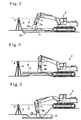
- Figs. 1 to 3 are plan views each showing a state in which a civil engineering work is being carried out by a shovel car 2 equipped with a laser beam detecting device 1 for a construction machine according to the present invention.
- Fig. 1 shows an example of an ordinary work
- Fig. 2 shows an example of a banking work
- Fig. 3 shows an example of a trenching work.
- the reference numeral 10 denotes a detection range of a leveled land (formed land surface).
- a reference position 11 of the leveled land is a standard position.
- a reference position 12 of the leveled land is a first offset position offset upward from the standard position shown in Fig. 1.
- a reference position 13 of the leveled land is a second offset position offset downward from the reference position 11 shown in Fig. 1.
- a rotating laser 4 is installed at a predetermined position of the leveled land or a land adjacent thereto through a tripod 3.
- a laser beam P emitted from the rotating laser 4 forms a reference plane.
- the laser beam detecting device 1 which is for indicating an appropriate height to an operator on the construction machine 2 in cooperation with the laser beam P, is attached to an arm portion 2a of the construction machine 2.
- the laser beam detecting device 1 has a beam sensor 5 for detecting the laser beam P and a display 6 for indicating an offset from the appropriate height to the operator on the construction machine 2 on the basis of the result of the detection.
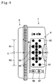
- the beam sensor 5 is disposed at a front position of the laser beam detecting device 1. In a detection range of the beam sensor 5 are disposed an upper range R1 and a lower range R2 with respect to a center C. The ranges R1 and R2 are each about 10 cm in size. A laser beam is transmitted from left to right in Fig. 4 and can enter the detection range of the beam sensor 5.
- a large number of light emitting elements e.g., LEDs
- Nine rows are set in the vertical direction.
- two, one, three, one, three, one, three, one, three, one, and two light emitting elements 61 are arranged in the nine rows, respectively.
- there are three rows each including three light emitting elements, all of which represent reference positions and of which the central row represents a standard position, while the upper and lower rows represent first and second offset positions, respectively.
- Marks 63, 64, and 65 which are light emitting elements, are arranged correspondingly to the rows indicative of those reference positions.
- the reference numeral 66 denotes a button for selecting any one of the mark 65 as the standard position and the marks 63 and 64 as the first and second offset positions.
- the positions of the marks 63, 64, and 65 which are set (i.e., go ON) at every depression of the button 66 by the operator, change rotationwise.
- the numeral 67 denotes a power switch for ON-OFF switching.
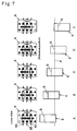
- Fig. 5 shows an example of position display in a normal state, in which the mark 65 at the standard position is ON.
- the laser beam P lies below the reference position (standard position) S of the beam sensor 5.
- the laser beam P lies above the reference position (standard position) S.
- Fig. 6 shows an upwardly offset state, in which the mark 63 located at the first offset position is ON.
- Fig. 7 shows a downwardly offset state, in which the mark 66 located at the second offset position is ON.
- the four light emitting elements 61 emit light in two modes (three light emitting elements which constitute a triangular shape and one light emitting element present at the established reference position), urging the operator to move the bucket 2b.
- the light emitting element present at the reference position serves as a reference indicating the width and direction of offset with respect to the three light emitting elements which constitute a triangular shape.
- a plurality of light emitting elements located at the reference position may be turned ON so as to represent a reference line.
- the light emitting elements 61 which have emitted light in a triangular shape go OFF and a transverse row of three light emitting elements 61 newly located at the reference position emit light, indicating completion of the movement.
- the light emitting elements 61 in a triangular form and the light emitting elements 61 located in the apex direction of the triangle are turned ON in an alternate manner, thereby making it easier to visually check the direction and width of offset.
- Fig. 8 shows a system for controlling the beam sensor 5 and the display 6.
- the beam sensor 5 for detecting the laser beam P has an analog circuit (not shown).
- a power supply 83 for the beam sensor is controlled by a microcomputer 81 which is incorporated in the body of the laser beam detecting device.
- the microcomputer 81 judges that no construction work is being conducted, then sets the operation mode to a sleep mode and turns OFF the power supply 83 for the beam sensor 5.
- a sleep reset signal which is inputted to the microcomputer 81 from a vibration sensor 82, becomes effective. This signal is for canceling the sleep state and is applied to the microcomputer 81 when vibration is detected by the vibration sensor 82.
- the vibration sensor 82 is power-supplied by the power supply 83, which is kept ON.
- the power consumption of the entire device is 300 mW in operation and is 49 mW in the sleep state.
- the analog circuit in the beam sensor 5 consumes electric power about five-sixths of the electric power consumed by the entire detecting device and thus the power saving effect in the sleep mode is high.
- the reason for such a large power consumption of the beam sensor 5 is that the beam sensor requires a large number of circuit channels for detecting a laser beam incidence position and that therefore a large electric power is consumed inevitably.
- the power supply 83 there are used four UM-3 charging cells of NiMH type.
- the ordinary type of dry cells or battery may also be used.
- Fig. 9 shows an example of the vibration sensor 82.
- the vibration sensor 82 is of a configuration similar to the configuration of a chip capacitor and possesses a characteristic such that a weak current is generated upon imposition of vibration on plural capacitors 91.
- the power consumption of the vibration sensor 82 is fairly weak and is 1 mW or so, even including the amplifier circuit.
- the vibration sensor 82 used in this embodiment is "PKGS-45LB-TC"(a product of Murata Manufacturing Company Limited).
- numeral 84 denotes an operator and numeral 66 denotes a switch for the microcomputer 81.
- vibration sensor 82 permits reduction of the power consumption in the entire laser beam detecting device. Particularly, where a battery or the like is used as a drive source, there no longer is any fear that the work may be interrupted by exhaustion of the battery, thus enhancing the working efficiency. Besides, by keeping the power consumption low, it is possible to reduce the battery capacity and lighten the device weight. That the device becomes light is advantageous in that the device becomes less likely to come off under a sudden shock and becomes easier to carry for installation in a construction machine.
- vibration sensor permits the device to be controlled accurately in conformity with the operating condition of the construction machine in which it is installed.
- the detection range can be widened greatly, so that even a banking or trenching work can be carried out efficiently.
- a leveling work can be executed in an efficient manner.
- the detection range in one direction is to be expanded, this can be attained by setting a reference position in the laser beam detection range at the first or the second offset position.
- a reference position in the laser beam detection range is set at the upper, first offset position, the leveling implement (bucket) does not move deeper than the to-be-trenched depth except where excavation goes to excess. Therefore, even if the detection range lower than the to-be-trenched depth is narrow, it will do.
Abstract
Description
Claims (6)
- A laser beam detecting device for a construction machine wherein a beam sensor is installed above a leveling implement of the construction machine to detect a laser beam as a reference, and information based on the beam detection is displayed on a display,
characterized in that a plurality of reference positions can be set in a range in which the beam sensor detects the laser beam, and one of the reference positions is selected. - A laser beam detecting device for a construction machine according to claim 1, wherein one of the reference positions is made a standard position, while the other reference positions are made offset positions, and one reference position is selected from the standard position and the offset positions.
- A laser beam detecting device for a construction machine according to claim 1, wherein first and second offset positions are established respectively above and below the standard position.
- A laser beam detecting device for a construction machine according to any of claims 1 to 3, wherein which reference position is selected in the beam detection out of the standard position and the offset positions, is displayed on the display.
- A laser beam detecting device for a construction machine according to any of claims 1 to 4, wherein in which of upward and downward directions with respect to the selected reference position the laser beam is present, is displayed on the display.
- A laser beam detecting device for a construction machine according to any of claims 1 to 5, wherein the direction and width of offset between the selected reference position and the laser beam are displayed on the display.
Applications Claiming Priority (2)
| Application Number | Priority Date | Filing Date | Title |
|---|---|---|---|
| JP11168148A JP2000356516A (en) | 1999-06-15 | 1999-06-15 | Laser light detecting device for construction machine |
| JP16814899 | 1999-06-15 |
Publications (2)
| Publication Number | Publication Date |
|---|---|
| EP1061185A2 true EP1061185A2 (en) | 2000-12-20 |
| EP1061185A3 EP1061185A3 (en) | 2002-02-06 |
Family
ID=15862722
Family Applications (1)
| Application Number | Title | Priority Date | Filing Date |
|---|---|---|---|
| EP00112652A Withdrawn EP1061185A3 (en) | 1999-06-15 | 2000-06-15 | Laser beam detecting device for a construction machine |
Country Status (3)
| Country | Link |
|---|---|
| US (1) | US6665067B2 (en) |
| EP (1) | EP1061185A3 (en) |
| JP (1) | JP2000356516A (en) |
Cited By (4)
| Publication number | Priority date | Publication date | Assignee | Title |
|---|---|---|---|---|
| ES2220235A1 (en) * | 2004-06-11 | 2004-12-01 | Excavaciones Monzon Royo, S.L. | System for constructing trenches on concrete curb, has concrete mixer truck provided on gutter in parallel manner, concrete mixer arranged in opened bottom part of hopper, and mold attached to tractor |
| FR2928387A1 (en) * | 2008-03-10 | 2009-09-11 | Westline Sarl | METHOD AND SYSTEM FOR AUTOMATIC CALIBRATION OF EARTHMOVING MACHINERY |
| EP1770358A3 (en) * | 2005-09-30 | 2010-04-07 | Kabushiki Kaisha TOPCON | Laser level detection system |
| FR2996567A1 (en) * | 2012-10-04 | 2014-04-11 | Yves Blandin | Earthwork, loading and compaction device for constructing e.g. embankment, has control mechanisms reacting to laser to place cup in angular position in which shoe is disengaged from ground to perform earthwork or in compaction position |
Families Citing this family (13)
| Publication number | Priority date | Publication date | Assignee | Title |
|---|---|---|---|---|
| AU2001279795A1 (en) * | 2000-08-01 | 2002-02-13 | Mirko Essling | Measuring device and measuring method for determining distance and/or position |
| JP3816806B2 (en) * | 2002-01-21 | 2006-08-30 | 株式会社トプコン | Construction machine control system |
| US7023224B2 (en) * | 2002-03-18 | 2006-04-04 | Delphi Technologies, Inc. | Low power absolute position sensor and method |
| JP4069062B2 (en) * | 2003-11-20 | 2008-03-26 | 紘 下川 | Method of laying buried pipe and laying device used therefor |
| DE102004053686A1 (en) * | 2004-11-03 | 2006-05-04 | Essling, Mirko | Laser receiving device with improved accuracy and lower power consumption |
| DE112007001624B4 (en) * | 2006-07-12 | 2019-07-04 | Trimble Navigation Ltd. | Hand-held height-corrected laser light detector using a GPS receiver to provide two-dimensional position data |
| CN101680759B (en) * | 2007-05-30 | 2012-03-21 | 特林布尔公司 | Target for use in measuring and surveying applications |
| DE102010024014B4 (en) * | 2010-06-16 | 2016-04-21 | Trimble Jena Gmbh | Target for a geodetic device |
| EP2574412B1 (en) * | 2011-09-30 | 2014-06-18 | Siemens VAI Metals Technologies GmbH | Measuring probe, measuring system, method for laser optical recording of the height of a guide roller and use of the measuring system |
| EP2743399B1 (en) * | 2012-12-14 | 2015-09-30 | Joseph Vögele AG | Construction machine with adjustment assistance system for a sensor unit |
| US10294630B2 (en) * | 2017-09-06 | 2019-05-21 | Cnh Industrial America Llc | Method and system for creating a final graded soil surface having a final soil depth |
| US10683641B2 (en) * | 2018-07-11 | 2020-06-16 | Deere & Company | Depth guidance system for a work vehicle |
| CN114908825B (en) * | 2022-04-21 | 2023-09-22 | 武汉建工集团股份有限公司 | Intelligent soil surface leveling machine and application method thereof |
Citations (1)
| Publication number | Priority date | Publication date | Assignee | Title |
|---|---|---|---|---|
| US4884939A (en) * | 1987-12-28 | 1989-12-05 | Laser Alignment, Inc. | Self-contained laser-activated depth sensor for excavator |
Family Cites Families (11)
| Publication number | Priority date | Publication date | Assignee | Title |
|---|---|---|---|---|
| DE3506326C1 (en) | 1985-02-22 | 1986-08-21 | Harms, Paul G., 6253 Hadamar | Depth measuring device for an excavator |
| EP0262764A1 (en) * | 1986-09-30 | 1988-04-06 | Spectra-Physics, Inc. | Elevation indication system for a large earthworking implement |
| US4820041A (en) | 1986-11-12 | 1989-04-11 | Agtek Development Co., Inc. | Position sensing system for surveying and grading |
| US4945221A (en) | 1987-04-24 | 1990-07-31 | Laser Alignment, Inc. | Apparatus and method for controlling a hydraulic excavator |
| US4807131A (en) | 1987-04-28 | 1989-02-21 | Clegg Engineering, Inc. | Grading system |
| US4888890A (en) | 1988-11-14 | 1989-12-26 | Spectra-Physics, Inc. | Laser control of excavating machine digging depth |
| US5343033A (en) * | 1993-06-22 | 1994-08-30 | Apache Technology Inc. | Method and apparatus for detecting laser light having a plurality of pulse integrator and automatic gain control circuits |
| US6266623B1 (en) | 1994-11-21 | 2001-07-24 | Phatrat Technology, Inc. | Sport monitoring apparatus for determining loft time, speed, power absorbed and other factors such as height |
| JP3670075B2 (en) | 1996-03-06 | 2005-07-13 | 株式会社トプコン | Appropriate height display device |
| JP3827764B2 (en) * | 1996-03-19 | 2006-09-27 | 株式会社トプコン | Laser light detection display for construction machinery |
| JP3808599B2 (en) | 1997-08-25 | 2006-08-16 | 株式会社トプコン | Irradiation light detector |
-
1999
- 1999-06-15 JP JP11168148A patent/JP2000356516A/en active Pending
-
2000
- 2000-06-15 EP EP00112652A patent/EP1061185A3/en not_active Withdrawn
-
2002
- 2002-07-15 US US10/194,238 patent/US6665067B2/en not_active Expired - Lifetime
Patent Citations (1)
| Publication number | Priority date | Publication date | Assignee | Title |
|---|---|---|---|---|
| US4884939A (en) * | 1987-12-28 | 1989-12-05 | Laser Alignment, Inc. | Self-contained laser-activated depth sensor for excavator |
Cited By (5)
| Publication number | Priority date | Publication date | Assignee | Title |
|---|---|---|---|---|
| ES2220235A1 (en) * | 2004-06-11 | 2004-12-01 | Excavaciones Monzon Royo, S.L. | System for constructing trenches on concrete curb, has concrete mixer truck provided on gutter in parallel manner, concrete mixer arranged in opened bottom part of hopper, and mold attached to tractor |
| EP1770358A3 (en) * | 2005-09-30 | 2010-04-07 | Kabushiki Kaisha TOPCON | Laser level detection system |
| US7814670B2 (en) | 2005-09-30 | 2010-10-19 | Kabushiki Kaisha Topcon | Laser level detection system |
| FR2928387A1 (en) * | 2008-03-10 | 2009-09-11 | Westline Sarl | METHOD AND SYSTEM FOR AUTOMATIC CALIBRATION OF EARTHMOVING MACHINERY |
| FR2996567A1 (en) * | 2012-10-04 | 2014-04-11 | Yves Blandin | Earthwork, loading and compaction device for constructing e.g. embankment, has control mechanisms reacting to laser to place cup in angular position in which shoe is disengaged from ground to perform earthwork or in compaction position |
Also Published As
| Publication number | Publication date |
|---|---|
| JP2000356516A (en) | 2000-12-26 |
| US6665067B2 (en) | 2003-12-16 |
| US20020170210A1 (en) | 2002-11-21 |
| EP1061185A3 (en) | 2002-02-06 |
Similar Documents
| Publication | Publication Date | Title |
|---|---|---|
| US6665067B2 (en) | Laser beam detecting device for a construction machine | |
| US10017919B2 (en) | Construction management device for excavation machinery, construction management device for excavator, excavation machinery, and construction management system | |
| US6263595B1 (en) | Laser receiver and angle sensor mounted on an excavator | |
| US9567726B2 (en) | Machine control system for a wheel loader comprising a grading blade | |
| JP4920229B2 (en) | Laser level detection system | |
| CN103080437B (en) | Display system of hydraulic shovel, and control method therefor | |
| JP5706050B1 (en) | Work vehicle | |
| US9493929B2 (en) | Display system of excavating machine and excavating machine | |
| US20060123673A1 (en) | Grading control system | |
| US8091256B2 (en) | Loader elevation control system | |
| EP1434029A2 (en) | Position measuring system comprising a rotary laser | |
| JP3670075B2 (en) | Appropriate height display device | |
| JP2009137763A (en) | Device and method for monitoring stability of construction machine | |
| GB2420617A (en) | Excavator work linkage position determining system | |
| JPH09189581A (en) | Sensor-mounting structure of excavator and sensor unit | |
| JP2020029766A (en) | Leveling guide system for drilling machine or leveling machine | |
| EP1061184B1 (en) | Laser beam detecting device | |
| KR102081543B1 (en) | Smart slope warning lighting apparatus for preventing safety accident and operating method thereof | |
| JP7082906B2 (en) | Control device and control method | |
| US6470251B1 (en) | Light detector for multi-axis position control | |
| CN110312836B (en) | Bulldozer control method and bulldozer control device for construction machine | |
| US20230313502A1 (en) | Trench measurement system | |
| KR102631345B1 (en) | construction machinery | |
| KR20110006639U (en) | Slant sensing apparatus for Bucket of Loader | |
| JP2502998Y2 (en) | Angle detection device for main body of excavator excavator |
Legal Events
| Date | Code | Title | Description |
|---|---|---|---|
| PUAI | Public reference made under article 153(3) epc to a published international application that has entered the european phase |
Free format text: ORIGINAL CODE: 0009012 |
|
| AK | Designated contracting states |
Kind code of ref document: A2 Designated state(s): DE SE Kind code of ref document: A2 Designated state(s): AT BE CH CY DE DK ES FI FR GB GR IE IT LI LU MC NL PT SE |
|
| AX | Request for extension of the european patent |
Free format text: AL;LT;LV;MK;RO;SI |
|
| PUAL | Search report despatched |
Free format text: ORIGINAL CODE: 0009013 |
|
| AK | Designated contracting states |
Kind code of ref document: A3 Designated state(s): AT BE CH CY DE DK ES FI FR GB GR IE IT LI LU MC NL PT SE |
|
| AX | Request for extension of the european patent |
Free format text: AL;LT;LV;MK;RO;SI |
|
| RIC1 | Information provided on ipc code assigned before grant |
Free format text: 7E 02F 3/43 A, 7E 02F 9/26 B, 7G 01C 15/00 B, 7E 02F 3/84 B |
|
| 17P | Request for examination filed |
Effective date: 20020710 |
|
| AKX | Designation fees paid |
Free format text: DE SE |
|
| 17Q | First examination report despatched |
Effective date: 20021106 |
|
| STAA | Information on the status of an ep patent application or granted ep patent |
Free format text: STATUS: THE APPLICATION HAS BEEN WITHDRAWN |
|
| 18W | Application withdrawn |
Effective date: 20060131 |