EP1062983A2 - Elektromedizinisches Implantat - Google Patents
Elektromedizinisches Implantat Download PDFInfo
- Publication number
- EP1062983A2 EP1062983A2 EP00250200A EP00250200A EP1062983A2 EP 1062983 A2 EP1062983 A2 EP 1062983A2 EP 00250200 A EP00250200 A EP 00250200A EP 00250200 A EP00250200 A EP 00250200A EP 1062983 A2 EP1062983 A2 EP 1062983A2
- Authority
- EP
- European Patent Office
- Prior art keywords
- implant
- data
- external device
- handset
- service center
- Prior art date
- Legal status (The legal status is an assumption and is not a legal conclusion. Google has not performed a legal analysis and makes no representation as to the accuracy of the status listed.)
- Granted
Links
Images


Classifications
-
- A—HUMAN NECESSITIES
- A61—MEDICAL OR VETERINARY SCIENCE; HYGIENE
- A61N—ELECTROTHERAPY; MAGNETOTHERAPY; RADIATION THERAPY; ULTRASOUND THERAPY
- A61N1/00—Electrotherapy; Circuits therefor
- A61N1/18—Applying electric currents by contact electrodes
- A61N1/32—Applying electric currents by contact electrodes alternating or intermittent currents
- A61N1/36—Applying electric currents by contact electrodes alternating or intermittent currents for stimulation
- A61N1/372—Arrangements in connection with the implantation of stimulators
- A61N1/37211—Means for communicating with stimulators
Definitions
- the invention relates to an electromedical implant according to the preamble of claim 1.
- electromedical implants such as pacemakers, Defibrillators, cardioverters or other electronically operated or controlled Implants
- a telemetry device for exchanging data with an external device that has a transmitting device and a receiving device includes, the energy for sending and receiving is usually from a previously loaded buffer capacity.
- the invention is therefore based on the object of an electromedical Implant of the type mentioned with lower manufacturing costs and to provide lower energy requirements.
- the task is based on an electromedical implant the preamble of claim 1, by the in the characterizing part of the claim 1 specified features solved.
- the invention includes the technical teaching that an implant with smaller Manufacturing costs and lower energy requirements when received for the transmitter and the receiving device each has a separate energy store is provided. These energy storage devices only have to be adapted to the individual Necessary voltage to be charged and therefore only for this be interpreted, which is advantageous to the manufacturing costs of the implant affects. In addition, less energy goes through the lower required voltage multiplication lost. The energy consumption of broadcasting affects the further not the energy supply for receiving and vice versa. The processes can thus follow each other immediately, what a bidirectional communication protocol makes sense.
- the invention has a particularly advantageous effect in the field of long-range high-frequency telemetry.
- the energy stores are preferably each of a buffer capacity educated.
- the buffer capacities for the two energy stores are advantageously different large and will be sized according to the process to be supplied coordinated if, for example, a transmission process is more powerful than one Receiving process should need.
- the buffer memory can be used as required for unidirectional operation of the telemetry or both loaded at the same time with bidirectional operation of the telemetry become.
- the buffer stores are preferably each immediately before one Transmission process or a reception process loaded to avoid energy losses Avoid leakage currents during long-term maintenance of the state of charge.
- the transmission security can be increased in that the one energy storage serves as a safety reserve for the other energy storage device. This can at the same time the energy supply can be better used because when emptying the first energy storage no additional security reserve by additional Capacitors must be kept available.
- Figure 1 shows an apparatus for performing the method according to the invention with an electromedical implant 1 using a telemetry device is provided and an external device 2, which consists of a handset 3 and a base station 4 exists.
- the handset 3 has a control device 5 and a first interface device 6, a mobile radio device 7, a second interface device 8, a man-machine interface 9 and a third interface device 16 on, which are each connected to the control device 5.
- the first interface device 6 is with the control device 5 indirectly via another Interface device 17 connected.
- the handset is powered via Li-ion batteries, which are accommodated in the power supply part 10.
- the first interface device 6 consists of a telemetry transmitter / receiver unit, so that the handset 3 contact via a bidirectional telemetry line can take up to the implant.
- Receiver and transmitter of the interface device 6 are integrated in an IC. Both circuit parts form a functional one Unit.
- the receiver and transmitter preferably work in the UHF range 403.55 MHz, 4, 8, 16 and 32 kbit / s are provided as baud rate levels. Possible but especially for the implant 1, the use of more energy-saving Frequencies in the VHF or LF range.
- the mobile radio device 7 can transmit data, for example, via the first interface device 6 were read out of the implant in the form of SMS messages send and from one as a monitoring device or central Storage facility serving service center can be called.
- a connection between the handset can be established via the second interface device 8 3 and base station 4 are manufactured. It is an infrared interface (IrDA) educated. It works bidirectionally and can process data in half-duplex mode transfer.
- IrDA infrared interface
- the man-machine interface 9 enables the handset 3 to be operated by a user.
- the third interface device 16 is used for recording external data or used for service. It is also designed as an IrDA interface.
- the serial interface for both IrDA interface devices 8 and 16 and the interface to the mobile radio device 7 are parallel, so that only one Unit can be operated.
- the IrDA interfaces 8 and 16 are parallel switched. Both interfaces are always ready to receive, so that at any time external request can be served. The software only needs to be there determine which IrDA interface the receive request is at.
- the power supply of the handset 3 is realized with Li-ion batteries. You can the handset 3 in the fully charged state for at least 20 hours (standby time + 16 SMS transmissions). The dimensions of the batteries apply at the end of their service life. A 1000 mAh Li-ion battery is therefore provided.
- the telemetry unit 6 for communication with the implant 1 including a transmit / receive antenna and control electronics for telemetry and an interface device 17 housed in a separate module.
- This separate module points an interface device 17 for electrical and possibly also mechanical Connect to a mobile phone.
- the separate module can, for example, instead of the battery pack in the mobile phone be used so that there is a mechanically stable unit from a mobile phone and separate housing, which may be the previous outer contour of the mobile phone is slightly overlooked.
- the separate module has a battery compartment in which the original battery pack of the mobile phone or another suitable battery or a suitable battery pack can be inserted. This battery then serves for powering the entire system from a mobile phone and a separate module and can be charged via the standard charging connections on the mobile phone.
- the second variant additionally requires the plug to be integrated in the battery compartment a mechanical and electrical modification of the mobile phone.
- this connector not only to the serial interface but also with other parts of the electronics of the cell phone can be direct Control of the mobile phone can be made possible by the telemetry unit.
- the electronics of the mobile phone can be controlled by the permanently on standby or optionally time-controlled Telemetry unit can be put into operation automatically if necessary (event control).
- the separate module can be integrated on a SIM card his.
- This SIM module is inserted in the SIM card slot instead of the standard SIM card inserted and uses the standard intended for this Interface.
- the transmitting / receiving antenna and the control electronics can, for example be designed for telemetry so that when inserted SIM module are arranged outside the housing of the mobile phone.
- Handset 3 man-machine interface
- a flashing LED indicates the low battery status as soon as the battery charge has dropped to 10%.
- the handset 3 then still has a minimum of about 2 hours Power reserve. Since the handset 3 is not always visible to the patient, the buzzer also indicates the occurrence of the low battery state by means of a short alarm on. The buzzer must be at a frequency of approximately 2 kHz or below work and be correspondingly loud, so that even limited perception Patients can hear the alarm sound safely. The buzzer should be about everyone 5 minutes again trigger alarm to let the patient charge the battery to remember.
- a recessed on / off switch is provided which does not operate unintentionally can be.
- the switch position is labeled so that you can see whether that Handset 3 is switched on. This switch is necessary because the handset 3 with the mobile radio device 7 can be switched off in some surrounding areas must, e.g. B. during a flight and in certain areas of hospitals.
- a button can be provided to send a short message for testing the SMS channel to be sent to the service center.
- the handset 3 shows a blinking LED indicates that such a test has been started.
- the service center recognizes that received short message as a test and sends an acknowledgment to the handset 3. Thereupon the blinking of the LED is stopped again, which means for the patient it can be seen that both the outward and return connection to the service center function.
- a button can be provided for diagnostic purposes, by means of which the Patient can trigger data transfers to the service center. Occur at the patient Complaints of any kind that may not be considered for the implant such are recognizable, this button can be pressed. Then a Data record transferred in addition to the information to be routinely transferred the time of triggering and the acquisition of the associated data by the Contains implant. The service center is transmitted by the short message also informed that this is a patient-triggered data transmission acts, which may have to be treated separately.
- a patient alarm button can be used, which is also available unintentional incorrect operation is protected.
- This emergency button can go to this Purpose sunk and additionally protected by a lid that must first be opened to trigger the patient alarm. Protection against incorrect operation can also be implemented as a timeout in the software that the Key function only accepts as valid if the key is longer (e.g. more than 3 s) is pressed.
- a successfully triggered patient alarm is signaled acoustically by the Buzzer acknowledged.
- the button can then be released. Still is a light emitting diode is switched on for 10s and then lights up again every minute for 2s as a reminder of a triggered patient alarm. The buzzer will always operated simultaneously with the light-emitting diode, so that also in the perception Restricted patients can see this receipt from the external device.
- a patient alarm is immediately forwarded to the service center via SMS. He is only deleted when the service center clears the patient alarm - also via SMS - acknowledged and so it is ensured that the alarm in the service center has arrived.
- the acknowledgment of the alarm by the service center is also indicated by LED and buzzer on handset 3.
- the handset 3 If an unacknowledged patient alarm is to be deleted, the handset 3 turned off. After the restart, the handset is back in normal condition. The handset automatically reports back to the service center via SMS. There it can then be recognized that the external device has been reset and the patient alarm is cleared.
- the successful execution of a patient alarm has compared to the low battery display a higher priority.
- the low battery display will only come back displayed when the service center has acknowledged the patient alarm. Should one The handset 3 is used to prevent interference with the surroundings from the buzzer turn off.
- the software is in a flash ROM via the IrDA interface 16 downloadable.
- the storage capacity of the internal flash ROM is 128 KB, that of the integrated EEPROM 4 KByte and that of the static, external SRAM 64 Kbyte.
- the program memory size is therefore based on the capacity of the built-in Flash ROMs limited and cannot be expanded (Harvard structure).
- the external static SRAM is expandable.
- a 128 bit DES encryption method is used for the SMS transmission, which is based on a private-public key system.
- the encryption will implemented in software, i.e. no encryption IC is used.
- a watchdog circuit is provided that is in regular use Processor 5 checked distance and back to a safe status transferred if the program execution does not run correctly.
- the field strength information via SMS with the corresponding numbers of the current and adjoined cells and the Bit error rate is transmitted. Based on this location information is a location of the mobile device 3 in emergencies in which the patient is unable to act.
- the mobile radio device 7 comprises a mobile radio module 7.1 and a SIM (subscriber Identity Module) card 7.2 trained memory.
- the SIM card reader can be soldered directly into the circuit board under the cell phone module 7.1.
- the SIM card 7.2 is therefore not accessible to the user.
- a SIM card reader available anyway.
- the cell phone module 7.1 In the memory of the SIM card 7.2, the cell phone module 7.1 the number (s) of the service center permanently stored.
- the handset 3 is with delivered a SIM card, which is the default in the number memory Contains a service center number.
- the phone numbers on the SIM card can be changed. Number management (writing and reading the Numbers on and from the SIM card) must be from the central control device 5 of the external device.
- the preset number will open the SIM card is kept permanently in another storage location for security and used when the external device 2 with a new number no connection can build up. This ensures that contact is made always remains possible.
- Several service centers can also be operated.
- the patient reports at any service center. This is the address of the Customers are known and it can be decided which service center is to be used first takes over the service. If the customer switches on his external device, then it registers with the pre-set service center by immediately Sends an SMS message to them. The service center can now by return send the SMS number that will be used in the future shall be.
- the handset 3 can thus automatically switch to another service center at any time can be assigned without a service technician moving the handset 3 ought to. This makes particular sense if it can avoid that SMS messages must be sent across borders.
- the databases of the service centers compare with each other, so that always it is clear which implant 1 or handset 3 is operated by which service center becomes. Appropriate fields must be provided in the database.
- a type of LiFo memory can also be inserted in the SIM card for maximum memory depth (e.g. ten numbers) can be organized. Gives the previously responsible service center a new number, it is used as the most recent number. However, if there are transmission problems with this new number, each time uses the next older number until the permanent one It is the turn of the preset number. If the memory is occupied, e.g. with 9 Phone numbers and the preset phone number, the oldest, i.e. the phone number, closest to the preset is deleted.
- the advantage of this The procedure is its high redundancy, since it can be assumed that with at least one of the stored service centers establishes a connection.
- the disadvantage is that many service centers may have data from an external Receive the device, which is then compiled and evaluated together can be.
- the call number memory can also used in the SIM card for these phone numbers become.
- the organization can be based on the management of mobile phone numbers shape.
- the base station 4 consists of a charger 11 for the batteries in the power supply part 10 and a modem 12 acting as a data transmission device for the fixed telecommunications network 13 from the handset 3 via the interface device 14 is addressed.
- the base station 4 further includes one Additional antenna 15, which when connected to the handset 3 with the mobile radio device 7 is connected and thus improves the transmission quality.
- the charger 11 is used to charge the Li-ion batteries of the handset 3 and at the same time supplying the components of the base station 4.
- the charger is with a controller suitable for Li-ion batteries and a monitoring circuit equipped. It is designed for a maximum charging current of 350mA. It is switchable for a primary AC voltage of 220 / 110V, 50 / 60Hz, with a range of 100 to 240 V for the primary AC voltage and a frequency range of 47-63 Hz is preferred. It becomes protection class 2 for the external device 2 used.
- the power supply in the base station 4 can also be replaced by a suitable plug-in power supply.
- the interface device 14 is designed as an infrared interface (IrDA).
- the additional antenna 15 is designed as a diversity antenna. They are all suitable ⁇ / 4 antennas are provided, which are designed as loop or helix antennas are.
- External device 2 interaction of handset 3 and base station 4
- the handset 3 is used for charging and data transmission over the fixed telecommunications network 13 inserted into the base station 4.
- the base station 4 is equipped with a light emitting diode which lights up when that Handset 3 is plugged in and a charging current charges the batteries.
- the light emitting diode goes out when the handset 3 is removed or there is no more power from the handset 3 is recorded.
- the display of the light emitting diode is but inverted at least a second if over the built-in Modem 12 sends or receives a message.
- the base station 4 acknowledges inserting the handset 3 or removing the handset 3 a short tone of a buzzer.
- the handset 3 is fully functional during charging in the base station 4.
- the voltage converters in the base station are designed up to 40 V, so that a Connection for charging from a motor vehicle network is possible.
- the control device 5 monitors the battery voltage and the power supply on the cell phone module 7.1. When handset 3 is switched on, the batteries are in the base station after approx. 4 hours fully charged again.
- the control device 5 is designed so that only after a predetermined number of unsuccessful transmission attempts via the mobile radio device 7 the transmission of the data to the monitoring device via the Fixed telecommunications network 13 by means of the interface devices 8 and 14 and the modem 12 takes place. So if the cellular transmission doesn't work or the external device 2 is operated in a country that does not have a mobile radio standard supported, i.e. are in the handset 3, data in the memory of the SIM card 7.2 temporarily stored and not via the mobile network to the service center could be transmitted, the transmission takes place via the modem, as soon as the handset is plugged into the base station.
- the IR interface 8 of the handset 3 and the IR interface 14 of the base station 4 are always ready to receive.
- the handset 3 exchanges with the base station 4 Data as soon as it is plugged into it. This is the handset 3 each known whether a functional modem 12 is present in the base station 4.
- the modem 12 is either integrated in the base station 4 or, if necessary, by the Service technician can be connected by simply snapping into the base station 4 becomes.
- the modem 12 can be switched to a software handshake because only this type of "optical 2-wire transmission" via the IrDA interfaces 8 and 14 is supported.
- the external device 2 If an error in operation is detected, a corresponding request from the service center the external device 2 receives or goes on again after a power-on reset Network, external device 2 carries out a self-test and reports the result the service center.
- the external device 2 reports errors automatically, can be Check from the service center and report back when it comes back is ready for operation (e.g. after recharging the discharged batteries).
- the SMS string with the result of the self-test is only transmitted if the above three preconditions this requires, in the normal transmission string there is no information about Self-test included.
- External device 2 time synchronization
- the microprocessors in external devices with their real-time clock is only that relative time available.
- the time in implant 1 is not adjusted and after one half year to within +/- 0.5 hours, so that they can set the system time of the external device 2 cannot be used. If the handset 3 If the battery becomes empty or is removed by the service technician, it can do so come that the real-time clock loses time completely.
- the external device is required but the current time to be specified in connection with data sent to the service center be sent to document when events from the implant 1 were received.
- the data are sent as SMS messages, incoming messages are sent to the external device by the service center via SMS 2 acknowledged.
- SMS 2 To set the current time in external device 2, i. H. a time synchronization of the external device 2, the time signature (SMS header) of the receipt SMS used, which contains the date and time.
- this acknowledgment SMS comes within e.g. a minute back it can external device 2 set the absolute time after the header of the receipt, because it is guaranteed that both SMS were under way for less than a minute. Is It may have been a long time between the SMS sent and the receipt The SMS header of the receipt cannot be evaluated because it cannot be determined whether the original broadcast or the receipt was delayed. The Experience has shown that the time for an SMS transmission is less than 10s, so that one can use the above procedure well.
- both the service center and the external one Device 2 can be operated with the UTC time. So the whole system works on one time.
- the local time such as MEZ or MESZ must then when creating Doctor's letters can be determined from the UTC time.
- Such a Service is usually provided by different providers for the public telephone network made available.
- External device 2 service interface
- a service technician can, for example, use the interface device 16 using e.g. a laptop communicate with the handset 3.
- Another Possibility is that the external device works as a data logger by data (e.g. as a blood sugar monitor), which are then also sent to the SMS Service center can be sent.
- the range of the interface device 16 is at least 0.4 m. She is arranged so that it is from a device that is next to the external device 2, can be used when the handset 3 is inserted in the base station 4. she works bidirectionally and can transmit data in half-duplex mode. The transmission speed the third interface device 16 is at least 9600 baud and can then be switched up to 115 Kbaud.
- the third interface device 16 is to be arranged so that the communication between base station 4 and handset 3 works safely, i.e. Influences the second interface device 8 by the third interface device 16 excluded are.
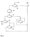
- Figure 2 shows a flow chart of one in connection with the invention Method applicable method for data transmission, that for data transmission can be used between the implant 1 and the external device 2 can.
- the trigger signal for data transmission is always from the transmitter / receiver unit of the implant 1, for which purpose the transmitter / receiver unit in a step 18 is switched on.
- step 19 the first data is then transferred from the implant 1 to the external device 2.
- a string consisting of 17 bytes is transmitted. These are 1 byte synchronization, 4 byte identification, 1 byte sequential number the transmission, 1 byte length of the transmitting string, 8 bytes of data, 2 bytes Security (CRC).
- CRC 2 bytes Security
- step 20 there is then a plausibility check of the first sent Data from the external device.
- the CRC bits related to the string sent or a check to see if the Synchronization bits have the previously known values.
- the string length matches the transmitted string length and / or whether the serial number of the transmission is correct.
- a review of flags is omitted since the external device 2 does not handle the flags.
- Extensions to telemetry can therefore always be the same type of external Device. There is no need to check the implant number because the external device can forward the information of several implants.
- Step 22 determines whether a predetermined number of retransmissions was exceeded.
- step 22 It is determined in step 22 that the predetermined number of retransmissions not exceeded, valid data from the Pacemaker requested.
- This request can be made from synchronization (8 bit), identification (32 bit), the serial number of the message (8 bit) and an agreed Code (8 bit) exist.
- Step 21 after the plausibility check has been carried out, a first receipt to the Implant 1 sent, the first acknowledgment for the first control information Control of the readiness to receive the first transmitter / receiver unit contains. If the data record was recognized as valid, you can use or in the first Received a control record that controls through the implant 1 becomes. There are two options:
- the previously sent first data record is completely sent to the Implant 1 sent back, which is then the one sent with the one received Compares record. Then 187 bits would be sent back.
- step 24 If the first receipt in the implant is negative in step 24, i.e. if the control data are not identical to the original data, the shipment is made of the first record again. The implant then tries a set one Time span again. The external device 2 informs the service center about the number of incorrectly transmitted data packets.
- step 26 the implant 1 then stops all transmission and reception activities.
- step 27 the expiry of a specific time interval is checked, after which a new data record is pending in the implant.
- the handset 3 After receiving the second receipt, the handset 3 is now verified forward the first data to the service center.
- the first record is valid marked and the service center knows that this data with a very high Probability are correct.
- the external device keeps this first data until the implant delivers a new, correctly verified data set.
- the first data will still be sent via SMS sent to the service center, but it is also sent from the external device 2 reported that the second receipt of the implant 1 was not validly transmitted could be.
- the implant 1 after sending the second receipt after a precisely defined time interval Reception goes.
- the external device 2 can, for example Resend the first 88-bit receipt to a new shipment to request.
- the implant 1 can immediately after it has checked that it has responded is to begin the re-transmission without first having received the Data must be evaluated.
- the external device 2 then either the first data record or the second receipt is duplicated and can now decide whether the first record can be accepted as valid.
- the send / receive cycles can be repeated several times. But it has to go In order to save energy, care should be taken that after a certain Number of shipments is canceled to the energy storage of the implant not to discharge unnecessarily.
- the external device should then still send the data to the Send the service center, but the data must be marked as not verified.
- the data is held in the external device 2 until a new data record is dated Implant is sent.
- the last valid data record should be in the external Device that the service center can then query. With several Implants that work together with the external device 2 are each to keep the last records of each implant in the external device 2.
- the receiver of the external device 2 is in the described variant of the Procedure ready at any time to receive data from the implant.
- Zu Shipments from the Implant 1 sent to the external device 2 which either contain data or only indicate that the implant 1 is active and ready to receive. Is more than one Send message, they will be sent one after the other. These broadcasts are received, analyzed and acknowledged by the external partner. The Receipts are expected in a fixed time window after the broadcast, so that the recipient in the implant 1 only has to be active for a short time. In the receipts data can already be transferred to implant 1. Based on the content and The type of the acknowledgments is shown whether there are 2 additional data in the external device Pending transfer in the direction of implant 1.
- a reduction in energy consumption in the external device 2 achieved.
- the implant and the external device are synchronized by setting on time slices, which defines periodic times in which the Receiver of the external device is active.
- the implant 1 may then only send within these time slices to be received.
- the above Instructions are modified accordingly, so that the Implant 1 can only send within the time slices and no longer to any Times.
- the time slices can be used in the normal bidirectional manner described above Communication in the duration of the active as well as the passive phase as well as the synchronization time can be changed. Be about one no more consignments are received from the implant for a certain period of time the active time slice is gradually extended to one at the expense of the passive To drift apart the synchronicity. In extreme cases, the recipient is permanently active in the external device. This is also the reset state when switching on.
- FIG. 3 shows as a flowchart which strategy for the repetitions shipments can be driven through the implant 1.
- Figure 3 represents step 22 from FIG. 2 with the input 22.1 and the outputs 22.2 and 22.3 in detail.
- step 28 it is first checked whether a counter Z has a predetermined first Value, here 2, has not yet exceeded.
- the counter Z represents the Number of attempts to transfer. It goes to zero in step 18 set and incremented by 1 with each step of step 19. Is the default If the first value is not exceeded, a new one is immediately output 22.2 Transfer initiated. So first a second attempt is made to close the program transfer.
- step 29 Set to zero.
- step 30 it is checked whether the counter Z has a predetermined second value, here 3, has not yet exceeded.
- the specified second value is not yet exceeded, the system waits noticeably through the queue 31, because of a systematic error in the transmission can be assumed. This can e.g. be a jammer that makes transmission impossible for some time (e.g. an insufficiently suppressed electrical device). After a waiting period of e.g. B. 5 Another attempt to send is started within minutes. If this is also unsuccessful, the cycle continues at step 28.
- step 32 It is then checked in step 32 whether the counter Z has a predetermined third value, here 4, has not yet exceeded. Is the specified third value not yet exceeded, the system waits longer through queue 33, for example 1 hour and starts a last transmission attempt. Is this also unsuccessful, the cycle continues at step 28 and then exits at 22.3. In this case, the data will only be sent again when there is new data in the pacemaker Shipment ready.
- a predetermined third value here 4
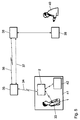
- FIG. 4 shows a block diagram of a variant of a patient monitoring system using the present invention.
- Data is transferred between the implant 1 and the external one Device 2 from Figure 1, the implant 1 is carried by a patient 33.
- the data read out are transmitted from the external device 2 via a mobile radio link 34 of a cellular network to a cellular station 35 of the cellular network transmitted and from there also via a mobile radio link 36 or alternatively sent via a landline connection 37 to a service center 38, which as central storage device and monitoring device is used. All data are sent as SMS messages and mutually acknowledged via SMS.
- the central storage unit 38 is equipped with a fully automatic database.
- the medical data is automatically in via TCP / IP connection the database computer is read in, depending on the time, implant, Patient, external device and medical contact (doctor / clinic) in the provided tables and table fields.
- the access options to the data are regulated by complex rights distribution (e.g. reading, writing, changing, deleting, etc.) for different User groups such as data administrators, clinics or doctors.
- complex rights distribution e.g. reading, writing, changing, deleting, etc.
- User groups such as data administrators, clinics or doctors.
- During the operation of the Database are manual interventions and queries by system administrators at any time and other clients (e.g. the doctor 40) possible.
- Priority-controlled triggers in the database and a coupled expert system make it possible to react specifically to medical issues:
- the Database generates information for the doctor according to predefined rules and the system administrator and gives them via fax, email, internal and external Computer connection to the target devices 39 on.
- the information output are stored in the database for later collective queries. So he can Doctor a summary or lost report regarding the patient request again. He also gets medical information in a few minutes during the investigation and summarized information to the next Follow-up appointment.
- the transmission medium and the destination addresses are included configurable depending on the time and event of the discharge. This allows the attending doctor 40 in a manner desired by him received about the health of his patient 33
- the patient 33 can also get medical help faster than usual. This emergency is both measured by objectively measured medical data also triggered by pressing a button on the handset 3 2. He receives towards the other events top priority.
- the database can also be set up separately for the patient Data transfers react, for example in this case also information be sent to the doctor and the system administrator. This can do that subjective condition of the patient especially when collecting data be taken into account and included in the diagnostic options.
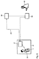
- FIG. 5 shows a block diagram of a variant of a patient monitoring and aftercare system using the present invention.
- the patient 33 with the implant 1 and the external device is located here 2 for aftercare examination in a query area 41 of a aftercare facility. It is triggered by the external device when entering the Interrogation area 41 cooperating trigger device automatically Querying the first data from the implant 1 before the follow-up examination performed by the doctor 40.
- the first data is transferred by means of the long-range telemetry connection between the implant 1 and the external device 2.
- the result of the query is processed in accordance with FIG. 4 described route via the service center 38 to the target device 39, from which it is the doctor 40 is issued for his information. At the same time further patient-related data from the database of the service center 38 output so that the doctor 40 can get a comprehensive picture.
- the routine, immediate examination of the doctor is thus an overall picture added to the time since the last visit to the doctor.
- the doctor receives a picture about for several weeks or months, which is much more meaningful than that current investigation.
- the patient's habits become good pictured, whereas the appointment with the doctor is an exceptional situation from can represent familiar life (trip to the clinic or doctor, climbing stairs, Stress in traffic etc.).
- the doctor can also do the actual examination (e.g. during stress tests) Request a report from the service center 38 immediately, which will then appear after a few Minutes is delivered. This allows parameter changes to be made using the Programmers have been hired, checked immediately and optimized if necessary. Through storage in the database and further evaluation options the expert system or by comparing it to other cases may be more Reports are created. Through advances in medical knowledge so new relationships are recognized. These will then be given to the doctor next report communicated, without being informed of each of his Should check patients for possible effects.
- Figure 6 shows a variant of the embodiment of Figure 5, in the query area 41 of the aftercare device, an external device 2 'is permanently installed.
- the query is triggered as soon as the patient 33 with the implant 1 for one certain period of time is in the query range of the external device 2 '.
- the result of the query is processed directly from the external source Device 2 'to the target device 39, from which it to the doctor 40 for his information is issued.
- other patient-related connections are made via the connection 43 Data from the database of the service center 38 queried and on Target device 39 output, so that the doctor 40 also here a comprehensive picture can make.
- FIG. 7 shows a block diagram of a telemetry device of an electromedical device Implant used in conjunction with the present invention can.
- the telemetry device has a near field transmitter 44, an associated therewith Telemetry unit 45 and an antenna interface device connected to the telemetry unit 45 46, via which a near-field antenna 47 with the Near field transmitter / receiver unit is connected.
- the near field telemetry device and the far field telemetry device have separate energy storage 51 and 52.
- the other necessary system components for a telemetry device such as Buffer, sequence control, coding, decoding and driver with Threshold value detectors are integrated in the telemetry unit 45.
- the Far field telemetry equipment operates at substantially the same effective data rate how the near field telemetry device operated.
- Figure 8 shows the transmitter / receiver unit of an embodiment of the implant 1, in the energy stores 56 and 57 separate for the transmitter 54 and the receiver 55 are provided. These are separate buffer capacities 56 and 57. These capacities 56 and 57 only have to match those for the respective process necessary energy can be charged. The energy consumption of one process does not affect the energy supply for the other process. The operations can thus follow each other immediately, what a bidirectional communication protocol is advantageous without the need to charge a single buffer capacity would be required to double the energy content.
- FIG. 9 shows a circuit diagram of a transmitter according to the invention of the first transmitter / receiver unit a variant of the implant 1 from FIG. 1.
- a stable frequency-modulated transmitter is with two bipolar transistors 58, 59 can be realized, the first transistor 58 in a Colpitts or Clapp circuit with a SAW resonator 60 a SAW stabilized oscillator forms and the second transistor 59 serves as a buffer stage and antenna driver.
- the transistors 58, 59 are at maximum amplification with the lowest collector current designed.
- With a capacitance diode 61 in series with the SAW resonator 60 the frequency can be modulated. The frequency swing, and thus the data rate and / or the range of the transmitter, but can be increased in that the capacitance diode is replaced by a PIN diode, which is replaced by another Transistor is switched.
- a simple wire loop or an open wire (wire antenna) can be used as the antenna. serve in the contour of the head of the implant. Overall, this is at 400 MHz a power consumption of less than 1 mA with a range of several Meters possible.
- the circuit can be made directly from a high impedance Battery of the implant 1 fed buffer capacity or a low-resistance Battery are supplied. A charge pump is not required.
- FIG. 10 shows a further exemplary embodiment of a device according to the invention, which corresponds essentially to that of Figure 1, which is why here only the differences should be dealt with.
- Applications can be the remote monitoring of plants, e.g. the filling level of beverage or vending machines, the connection to the Building services, e.g. Control and monitoring of air conditioning or heating that Coupling to alarm systems or glass breakage detection systems, e.g. Intrusion notification via Mobile radio, the coupling to measuring systems, e.g. Weather stations or level meters on rivers, the coupling to systems for monitoring and influencing traffic, e.g. Sign bridges etc. It can also be used as a listening device or as a mobile phone can be used with special digital functions.
- the differences from the embodiment from FIG. 1 essentially concern this Handset 3 'of the external device 2' '.
- the first interface device comprises 4 potential-free inputs 6.1 via optocouplers and 4 potential-free outputs 6.2. Thanks to the potential separation of the inputs and outputs 6.1 and 6.2 is suitable the external device 2 '' for the monitoring and control of digital states.
- the receiving and transmitting part 6 from FIG. 1 is omitted; released serial interface 63 (RS 232) via a 9-pin connector led out.
- a software handshake with three lines is sufficient for the RS 232 (RXD, TXD, GND).
- the transmission rate is also limited to 9600 baud.
- the serial interface 63 is not designed to be potential-free.
- the connector of the mobile radio module 7.1 can be connected to a further connector 64 Microphone, a loudspeaker and optionally a buzzer (6 lines), so that for other areas of application a hearing / speaking combination and a Buzzer can be added.
- the inputs 6.1 are in range 1 at -3V to 1.5V L level, 3.5 to 8V H level and 10 mA input current; in area 2 at -3V to 8V L level, 18V to 30V H level and 10 mA input current.
- the status is recognized via an LED display at a maximum switching frequency of 100 Hz square wave and a separation voltage of 2.5kV.
- the outputs have 15 to 30V DC separate voltage supply, one Load current of 200mA, short-circuit protection, protection against thermal overload and a separation voltage of 2.5kV. Electrical isolation is via optocouplers, the power switching function is implemented via MOS-FETs.
Abstract
Description
- Figur 1
- ein Blockschaltbild eines bevorzugten Ausführungsbeispiels einer Vorrichtung zur Durchführung des erfindungsgemäßen Verfahrens;
- Figur 2
- einen Ablaufplan eines Verfahrens;
- Figur 3
- ein Detail aus Figur 2;
- Figur 4
- ein Blockschaltbild einer Variante eines Patientenüberwachungssystems unter Verwendung der vorliegenden Erfindung;
- Figur 5
- ein Blockschaltbild einer Variante eines Patientenüberwachungs- und nachsorgesystems unter Verwendung der vorliegenden Erfindung;
- Figur 6
- ein Blockschaltbild einer weiteren Variante eines Patientenüberwachungs- und nachsorgesystems unter Verwendung der vorliegenden Erfindung;
- Figur 7
- ein Blockschaltbild einer Telemetrieeinrichtung eines elektromedizinischen Implantats unter Verwendung der vorliegenden Erfindung;
- Figur 8
- die Sender/Empfängereinheit einer Variante der Ausführung aus Figur 1;
- Figur 9
- ein Schaltbild eines Senders einer Variante der Ausführung aus Figur 1;
- Figur 10
- ein Blockschaltbild einer weiteren bevorzugten Ausführung einer erfindungsgemäßen Vorrichtung.
- Ein gefährlicher Zustand wird vom Schrittmacher gemeldet.
- Die Übertragungsstrecke zum Schrittmacher funktioniert nicht.
- Ein Selbsttest des externen Geräts meldet einen Fehler.
- Bei Meldung eines Low-Battery-Zustandes vor dem Abschalten.
- Bei Patientenalarm, d.h. der Patient löst durch Drücken einer Taste des Interfaces 9 Alarm aus.
- Auf Anforderung durch die Servicezentrale.
Claims (8)
- Elektromedizinisches Implantat (1), insbesondere Herzschrittmacher, mit einer Telemetrieeinrichtung (53) zum Austauschen von Daten mit einem externen Gerät (2), die eine Sendeeinrichtung (54) und eine Empfangseinrichtung (55) umfaßt, dadurch gekennzeichnet, daß für die Sendeeinrichtung (54) und die Empfangseinrichtung (55) jeweils ein gesonderter Energiespeicher (56, 57) vorgesehen ist.
- Implantat nach Anspruch 1, dadurch gekennzeichnet, daß die Energiespeicher (56, 57) jeweils eine Pufferkapazität enthält.
- Implantat nach Anspruch 1 oder 2, dadurch gekennzeichnet, daß der Energiespeicher (56) für die Sendeeinrichtung (54) und der Energiespeicher (57) für die Empfangseinrichtung (55) eine unterschiedlich große Pufferkapazität enthalten.
- Implantat nach einem der vorstehenden Ansprüche, dadurch gekennzeichnet, daß die beiden Pufferkapazitäten der Energiespeicher (56, 57) je nach Bedarf einzeln aufladbar sind.
- Implantat nach einem der vorstehenden Ansprüche, dadurch gekennzeichnet, daß die Pufferkapazitäten der Energiespeicher (56, 57) unmittelbar vor einem Sendevorgang bzw. einem Empfangsvorgang aufgeladen werden.
- Implantat nach einem der vorstehenden Ansprüche, dadurch gekennzeichnet, daß der Energiespeicher (56) für die Sendeeinrichtung (54) als Reserve-Energiespeicher für die Empfangseinrichtung (55) dient.
- Implantat nach einem der vorstehenden Ansprüche, dadurch gekennzeichnet, daß der Energiespeicher (57) für die Empfangseinrichtung (55) als Reserve- Energiespeicher (54) dient.
- Implantat nach einem der vorstehenden Ansprüche, dadurch gekennzeichnet, daß die beiden Energiespeicher (56, 57) parallel oder in Serie zueinander schaltbar sind.
Applications Claiming Priority (2)
| Application Number | Priority Date | Filing Date | Title |
|---|---|---|---|
| DE19930245A DE19930245A1 (de) | 1999-06-25 | 1999-06-25 | Elektromedizinisches Implantat |
| DE19930245 | 1999-06-25 |
Publications (3)
| Publication Number | Publication Date |
|---|---|
| EP1062983A2 true EP1062983A2 (de) | 2000-12-27 |
| EP1062983A3 EP1062983A3 (de) | 2004-01-21 |
| EP1062983B1 EP1062983B1 (de) | 2014-01-22 |
Family
ID=7913238
Family Applications (1)
| Application Number | Title | Priority Date | Filing Date |
|---|---|---|---|
| EP00250200.3A Expired - Lifetime EP1062983B1 (de) | 1999-06-25 | 2000-06-23 | Elektromedizinisches Implantat |
Country Status (3)
| Country | Link |
|---|---|
| US (1) | US6804559B1 (de) |
| EP (1) | EP1062983B1 (de) |
| DE (1) | DE19930245A1 (de) |
Cited By (1)
| Publication number | Priority date | Publication date | Assignee | Title |
|---|---|---|---|---|
| FR2876295A1 (fr) * | 2004-10-12 | 2006-04-14 | Ela Medical Sa | Dispositif medical implantable actif comprenant un circuit de telemetrie rf |
Families Citing this family (35)
| Publication number | Priority date | Publication date | Assignee | Title |
|---|---|---|---|---|
| US7283580B2 (en) * | 2000-07-21 | 2007-10-16 | Itron, Inc. | Spread spectrum meter reading system utilizing low-speed/high-power frequency hopping |
| FI20010779A (fi) * | 2001-04-12 | 2002-10-13 | Nokia Corp | Menetelmä tiedonsiirtonopeuden kasvattamiseksi sekä vastaanotin, lähetin ja päätelaite |
| US7903043B2 (en) * | 2003-12-22 | 2011-03-08 | Cardiac Pacemakers, Inc. | Radio frequency antenna in a header of an implantable medical device |
| US7729776B2 (en) | 2001-12-19 | 2010-06-01 | Cardiac Pacemakers, Inc. | Implantable medical device with two or more telemetry systems |
| US6993393B2 (en) | 2001-12-19 | 2006-01-31 | Cardiac Pacemakers, Inc. | Telemetry duty cycle management system for an implantable medical device |
| US6985773B2 (en) * | 2002-02-07 | 2006-01-10 | Cardiac Pacemakers, Inc. | Methods and apparatuses for implantable medical device telemetry power management |
| US20050187593A1 (en) * | 2004-02-23 | 2005-08-25 | Medtronic, Inc. | Implantable medical device system with communication link to home appliances |
| WO2005099817A1 (en) | 2004-04-07 | 2005-10-27 | Cardiac Pacemakers, Inc. | Rf wake-up of implantable medical device |
| US20090030332A1 (en) * | 2005-01-26 | 2009-01-29 | Schecter Stuart O | microfabricated cardiac sensor with tactile feedback and method and apparatus for calibrating the same using a plurality of signals |
| US20060167529A1 (en) * | 2005-01-26 | 2006-07-27 | Schecter Stuart O | Method and algorithm for defining the pathologic state from a plurality of intrinsically and extrinsically derived signals |
| US20100312129A1 (en) | 2005-01-26 | 2010-12-09 | Schecter Stuart O | Cardiovascular haptic handle system |
| US7545272B2 (en) | 2005-02-08 | 2009-06-09 | Therasense, Inc. | RF tag on test strips, test strip vials and boxes |
| US7610065B2 (en) | 2005-02-28 | 2009-10-27 | Cardiac Pacemakers, Inc. | Method and apparatus for antenna selection in a diversity antenna system for communicating with implantable medical device |
| US7664553B2 (en) | 2005-04-27 | 2010-02-16 | Cardiac Pacemakers, Inc. | System and method for enabling communications with implantable medical devices |
| US9168383B2 (en) | 2005-10-14 | 2015-10-27 | Pacesetter, Inc. | Leadless cardiac pacemaker with conducted communication |
| EP2471452B1 (de) | 2005-10-14 | 2014-12-10 | Pacesetter, Inc. | Leitungsloser Herzschrittmacher und System |
| US8805526B2 (en) | 2006-05-03 | 2014-08-12 | Cardiac Pacemakers, Inc. | Configurable medical telemetry radio system |
| US8339262B2 (en) * | 2007-02-22 | 2012-12-25 | Autonamic Technologies, Inc. | Patient identification system |
| US20090063193A1 (en) | 2007-08-31 | 2009-03-05 | Mike Barton | Dashboard diagnostics for wireless patient communicator |
| US9848058B2 (en) | 2007-08-31 | 2017-12-19 | Cardiac Pacemakers, Inc. | Medical data transport over wireless life critical network employing dynamic communication link mapping |
| US7917226B2 (en) * | 2008-04-23 | 2011-03-29 | Enteromedics Inc. | Antenna arrangements for implantable therapy device |
| WO2010088687A1 (en) | 2009-02-02 | 2010-08-05 | Nanostim, Inc. | Leadless cardiac pacemaker with secondary fixation capability |
| US8319631B2 (en) | 2009-03-04 | 2012-11-27 | Cardiac Pacemakers, Inc. | Modular patient portable communicator for use in life critical network |
| US8812841B2 (en) | 2009-03-04 | 2014-08-19 | Cardiac Pacemakers, Inc. | Communications hub for use in life critical network |
| EP2627403A4 (de) | 2010-10-12 | 2014-03-26 | Nanostim Inc | Temperatursensor für einen bleifreien herzschrittmacher |
| US9060692B2 (en) | 2010-10-12 | 2015-06-23 | Pacesetter, Inc. | Temperature sensor for a leadless cardiac pacemaker |
| WO2012051235A1 (en) | 2010-10-13 | 2012-04-19 | Nanostim, Inc. | Leadless cardiac pacemaker with anti-unscrewing feature |
| EP2651494B1 (de) | 2010-12-13 | 2017-02-15 | Pacesetter, Inc. | Implantationskatheter |
| EP2651502B1 (de) | 2010-12-13 | 2016-11-09 | Pacesetter, Inc. | Herzschrittmacher-rückholsysteme |
| EP2654889B1 (de) | 2010-12-20 | 2017-03-01 | Pacesetter, Inc. | Elektrodenloser schrittmacher mit radialem befestigungsmechanismus |
| US8942828B1 (en) | 2011-04-13 | 2015-01-27 | Stuart Schecter, LLC | Minimally invasive cardiovascular support system with true haptic coupling |
| WO2013067496A2 (en) | 2011-11-04 | 2013-05-10 | Nanostim, Inc. | Leadless cardiac pacemaker with integral battery and redundant welds |
| US10013082B2 (en) | 2012-06-05 | 2018-07-03 | Stuart Schecter, LLC | Operating system with haptic interface for minimally invasive, hand-held surgical instrument |
| US9014626B2 (en) * | 2012-07-31 | 2015-04-21 | Raytheon Company | Low noise bias circuit for phased array antenna element |
| EP2879758B1 (de) | 2012-08-01 | 2018-04-18 | Pacesetter, Inc. | Biostimulatorschaltung mit fliegender zelle |
Family Cites Families (41)
| Publication number | Priority date | Publication date | Assignee | Title |
|---|---|---|---|---|
| US4172459A (en) | 1977-10-17 | 1979-10-30 | Medtronic, Inc. | Cardiac monitoring apparatus and monitor |
| US4166470A (en) * | 1977-10-17 | 1979-09-04 | Medtronic, Inc. | Externally controlled and powered cardiac stimulating apparatus |
| FR2491659B1 (fr) | 1980-10-07 | 1986-04-04 | Medtronic Inc | Dispositif de telemesure pour un stimulateur implantable |
| EP0108052A4 (de) | 1982-04-23 | 1985-09-26 | Survival Technology | Tragbare kontrolleinheit mit realzeitanalyse und übertragung über fernsprecher. |
| DE3220930A1 (de) | 1982-06-03 | 1983-12-08 | Siemens AG, 1000 Berlin und 8000 München | Zweiwegkommunikationssystem zwischen einem implantierbaren elektrischen stimulator und einer externen kontrolleinheit |
| US4741341A (en) | 1986-03-12 | 1988-05-03 | Siemens-Pacesetter, Inc. | Protection circuit and method for implanted ECG telemetry circuits |
| US4809697A (en) | 1987-10-14 | 1989-03-07 | Siemens-Pacesetter, Inc. | Interactive programming and diagnostic system for use with implantable pacemaker |
| EP0344770A1 (de) | 1988-06-01 | 1989-12-06 | State Of Israel-Ministry Of Agriculture | Vorrichtung zur drahtlosen Übermittlung der Impedanz von lebendem Gewebe |
| DE3831809A1 (de) | 1988-09-19 | 1990-03-22 | Funke Hermann | Zur mindestens teilweisen implantation im lebenden koerper bestimmtes geraet |
| US5531774A (en) * | 1989-09-22 | 1996-07-02 | Alfred E. Mann Foundation For Scientific Research | Multichannel implantable cochlear stimulator having programmable bipolar, monopolar or multipolar electrode configurations |
| DE3936547A1 (de) | 1989-11-02 | 1991-05-08 | Siemens Ag | Anordnung zur telemetrischen kommunikation zwischen zwei geraeten mittels eines magnetischen nahfeldes |
| US5127404A (en) | 1990-01-22 | 1992-07-07 | Medtronic, Inc. | Telemetry format for implanted medical device |
| US5187657A (en) | 1990-04-05 | 1993-02-16 | Hewlett-Packard Company | Cardiac analyzer with rem sleep detection |
| WO1991016696A1 (en) * | 1990-04-23 | 1991-10-31 | Siemens Aktiengesellschaft | High speed reflected impedance telemetry system for implantable device |
| US5197480A (en) | 1990-06-08 | 1993-03-30 | Vitatron Medical, B.V. | System and method for monitoring heart transplant rejection |
| US5139028A (en) | 1990-10-26 | 1992-08-18 | Telectronics Pacing Systems, Inc. | Heart rejection monitoring apparatus and method |
| DE4100568A1 (de) | 1991-01-11 | 1992-07-16 | Fehling Guido | Vorrichtung zur ueberwachung eines patienten auf abstossungsreaktionen eines implantierten organs |
| US5191891A (en) | 1991-09-10 | 1993-03-09 | Ralin, Inc. | Portable ECG monitor/recorder |
| EP0537936A1 (de) | 1991-10-17 | 1993-04-21 | Physio-Control Corporation | Faksimileübertragung von elektrokardiografischen Daten |
| US5353793A (en) | 1991-11-25 | 1994-10-11 | Oishi-Kogyo Company | Sensor apparatus |
| US5358514A (en) * | 1991-12-18 | 1994-10-25 | Alfred E. Mann Foundation For Scientific Research | Implantable microdevice with self-attaching electrodes |
| US5313953A (en) | 1992-01-14 | 1994-05-24 | Incontrol, Inc. | Implantable cardiac patient monitor |
| US5522396A (en) | 1992-05-12 | 1996-06-04 | Cardiac Telecom Corporation | Method and system for monitoring the heart of a patient |
| US5342408A (en) | 1993-01-07 | 1994-08-30 | Incontrol, Inc. | Telemetry system for an implantable cardiac device |
| US5411536A (en) | 1993-06-03 | 1995-05-02 | Intermedics, Inc. | Method and apparatus for communicating data between medical devices to improve detectability of errors |
| US5411031A (en) | 1993-11-24 | 1995-05-02 | Incontrol, Inc. | Implantable cardiac patient monitor |
| US5413594A (en) | 1993-12-09 | 1995-05-09 | Ventritex, Inc. | Method and apparatus for interrogating an implanted cardiac device |
| DE4341903A1 (de) | 1993-12-09 | 1995-06-14 | Josef Prof Dr Rer Nat Binder | Implantierbares telemetrisches Endosystem |
| US5729203A (en) | 1994-06-28 | 1998-03-17 | Colin Corporation | Emergency call system |
| US5626630A (en) | 1994-10-13 | 1997-05-06 | Ael Industries, Inc. | Medical telemetry system using an implanted passive transponder |
| US5562713A (en) | 1995-01-18 | 1996-10-08 | Pacesetter, Inc. | Bidirectional telemetry apparatus and method for implantable device |
| US5702431A (en) * | 1995-06-07 | 1997-12-30 | Sulzer Intermedics Inc. | Enhanced transcutaneous recharging system for battery powered implantable medical device |
| US5752976A (en) | 1995-06-23 | 1998-05-19 | Medtronic, Inc. | World wide patient location and data telemetry system for implantable medical devices |
| US5720770A (en) | 1995-10-06 | 1998-02-24 | Pacesetter, Inc. | Cardiac stimulation system with enhanced communication and control capability |
| DE19622154A1 (de) | 1995-10-30 | 1997-05-15 | Frank Dr Ing Moeller | Elektroakustisches Bauelement und Verfahren zur Fernidentifikation |
| SE9603099D0 (sv) | 1996-08-27 | 1996-08-27 | Pacesetter Ab | Medical implant |
| US5735887A (en) * | 1996-12-10 | 1998-04-07 | Exonix Corporation | Closed-loop, RF-coupled implanted medical device |
| US5814089A (en) * | 1996-12-18 | 1998-09-29 | Medtronic, Inc. | Leadless multisite implantable stimulus and diagnostic system |
| US5999857A (en) * | 1996-12-18 | 1999-12-07 | Medtronic, Inc. | Implantable device telemetry system and method |
| IT1290220B1 (it) | 1997-01-30 | 1998-10-22 | Ela Medical S P A | Sistema di teleassistenza per il controllo e la programmazione di cardiostimolatori e defibrillatori impiantiabili |
| AU8938598A (en) | 1997-03-27 | 1999-04-23 | Medtronic, Inc. | Implantable Medical Device Remote Expert Communications System For Coordina ted Implant And Follow-Up |
-
1999
- 1999-06-25 DE DE19930245A patent/DE19930245A1/de not_active Withdrawn
-
2000
- 2000-06-23 EP EP00250200.3A patent/EP1062983B1/de not_active Expired - Lifetime
- 2000-06-26 US US09/603,812 patent/US6804559B1/en not_active Expired - Lifetime
Non-Patent Citations (1)
| Title |
|---|
| None |
Cited By (3)
| Publication number | Priority date | Publication date | Assignee | Title |
|---|---|---|---|---|
| FR2876295A1 (fr) * | 2004-10-12 | 2006-04-14 | Ela Medical Sa | Dispositif medical implantable actif comprenant un circuit de telemetrie rf |
| EP1647303A1 (de) * | 2004-10-12 | 2006-04-19 | Ela Medical | Implantierbare aktive medizinische vorrichtung mit telemetrischem RF-Schaltkreis |
| US7747331B2 (en) | 2004-10-12 | 2010-06-29 | Ela Medical S.A.S. | Active implantable medical device which includes a circuit of RF telemetry |
Also Published As
| Publication number | Publication date |
|---|---|
| US6804559B1 (en) | 2004-10-12 |
| DE19930245A1 (de) | 2000-12-28 |
| EP1062983B1 (de) | 2014-01-22 |
| EP1062983A3 (de) | 2004-01-21 |
Similar Documents
| Publication | Publication Date | Title |
|---|---|---|
| EP1062981B1 (de) | Verfahren und System zur Datenübertragung bei der Implantatsüberwachung | |
| EP1062983B1 (de) | Elektromedizinisches Implantat | |
| EP1070517B1 (de) | Sender für die Telemetrieeinrichtung eines Implantats | |
| EP1062984B1 (de) | Vorrichtung zur Übertragung von Daten insbesondere aus einem elektromedizinischen Implantat | |
| EP1062985B1 (de) | Implantat mit Nah-und Fernfeldtelemetrie | |
| EP1062982B1 (de) | Verfahren zur Datenabfrage bei der Implantatsnachsorge | |
| EP1062980B1 (de) | Verfahren und Vorrichtung zur Datenübertragung zwischen einem elektromedizinischen Implantat und einem externen Gerät | |
| DE60111223T2 (de) | Tragbare erweiterungsvorrichtung für datenübertragung in einem kommunikationssystem einer medizinischen vorrichtung | |
| DE60034965T2 (de) | Dynamische brandbreitenüberwachung und -anpassung zur fernkommunikation mit einer medizinischen vorrichtung | |
| DE60012905T2 (de) | Peripheres speicherpflaster und zugriffsverfahren zur verwendung mit einer implantierbaren medizinischen vorrichtung | |
| DE60106141T2 (de) | Gerät zur informationsbeobachtung auf abstand für medizinische vorrichtung | |
| AT505966B1 (de) | Verfahren und system zur batterieladekontrolle von hörimplantaten | |
| DE3225223A1 (de) | Interaktive programmiereinrichtung fuer implantierbare biomedizinische vorrichtungen | |
| EP2196239A2 (de) | Implantierbares medizinisches Gerät mit Mobilfunk-Modem | |
| DE102010020733A1 (de) | Elektronisches Gerät | |
| DE10251900A1 (de) | Patientenüberwachungssystem und -verfahren | |
| DE60031440T2 (de) | Integriertes softwaresystem zur installation und verwaltung in implantierbaren medizinischen vorrichtungen | |
| EP0963734B1 (de) | Vorrichtung zur Aufzeichung und Übertragung von medizinischen Daten | |
| EP1382369A1 (de) | Vorrichtung zur Elektrotherapie und Verfahren zum Testen und Betreiben einer solchen Vorrichtung | |
| DE19804844A1 (de) | Verfahren und Vorrichtung zur Identifikation | |
| EP0526686A1 (de) | Intelligentes Fernmess- und Stellsystem | |
| EP1222836A1 (de) | System zum austausch von daten | |
| DE112021004582T5 (de) | Verfahren zum Priorisieren von Kommunikationsverbindungen für ein vollständig implantiertes LVAD-System | |
| EP4171299A2 (de) | Tragbare synchronisationsstation für einen inhalator, synchronisationssystem und verfahren zur detektion des systemzustandes eines synchronisationssystems | |
| DE112021005778T5 (de) | Verfahren zum Einstellen der Rate von "Suchimpulsen" in einem Tets-System |
Legal Events
| Date | Code | Title | Description |
|---|---|---|---|
| PUAI | Public reference made under article 153(3) epc to a published international application that has entered the european phase |
Free format text: ORIGINAL CODE: 0009012 |
|
| AK | Designated contracting states |
Kind code of ref document: A2 Designated state(s): AT BE CH CY DE DK ES FI FR GB GR IE IT LI LU MC NL PT SE |
|
| AX | Request for extension of the european patent |
Free format text: AL;LT;LV;MK;RO;SI |
|
| PUAL | Search report despatched |
Free format text: ORIGINAL CODE: 0009013 |
|
| AK | Designated contracting states |
Kind code of ref document: A3 Designated state(s): AT BE CH CY DE DK ES FI FR GB GR IE IT LI LU MC NL PT SE |
|
| AX | Request for extension of the european patent |
Extension state: AL LT LV MK RO SI |
|
| 17P | Request for examination filed |
Effective date: 20040721 |
|
| AKX | Designation fees paid |
Designated state(s): AT BE CH CY DE DK ES FI FR GB GR IE IT LI LU MC NL PT SE |
|
| 17Q | First examination report despatched |
Effective date: 20050523 |
|
| RAP1 | Party data changed (applicant data changed or rights of an application transferred) |
Owner name: BIOTRONIK GMBH & CO. KG |
|
| RAP1 | Party data changed (applicant data changed or rights of an application transferred) |
Owner name: BIOTRONIK SE & CO. KG |
|
| RAP1 | Party data changed (applicant data changed or rights of an application transferred) |
Owner name: BIOTRONIK SE & CO. KG |
|
| GRAP | Despatch of communication of intention to grant a patent |
Free format text: ORIGINAL CODE: EPIDOSNIGR1 |
|
| INTG | Intention to grant announced |
Effective date: 20131024 |
|
| GRAS | Grant fee paid |
Free format text: ORIGINAL CODE: EPIDOSNIGR3 |
|
| GRAA | (expected) grant |
Free format text: ORIGINAL CODE: 0009210 |
|
| AK | Designated contracting states |
Kind code of ref document: B1 Designated state(s): AT BE CH CY DE DK ES FI FR GB GR IE IT LI LU MC NL PT SE |
|
| REG | Reference to a national code |
Ref country code: GB Ref legal event code: FG4D Free format text: NOT ENGLISH |
|
| REG | Reference to a national code |
Ref country code: CH Ref legal event code: EP |
|
| REG | Reference to a national code |
Ref country code: AT Ref legal event code: REF Ref document number: 650487 Country of ref document: AT Kind code of ref document: T Effective date: 20140215 |
|
| REG | Reference to a national code |
Ref country code: IE Ref legal event code: FG4D Free format text: LANGUAGE OF EP DOCUMENT: GERMAN |
|
| REG | Reference to a national code |
Ref country code: DE Ref legal event code: R096 Ref document number: 50016352 Country of ref document: DE Effective date: 20140227 |
|
| REG | Reference to a national code |
Ref country code: NL Ref legal event code: VDEP Effective date: 20140122 |
|
| PG25 | Lapsed in a contracting state [announced via postgrant information from national office to epo] |
Ref country code: NL Free format text: LAPSE BECAUSE OF FAILURE TO SUBMIT A TRANSLATION OF THE DESCRIPTION OR TO PAY THE FEE WITHIN THE PRESCRIBED TIME-LIMIT Effective date: 20140122 Ref country code: PT Free format text: LAPSE BECAUSE OF FAILURE TO SUBMIT A TRANSLATION OF THE DESCRIPTION OR TO PAY THE FEE WITHIN THE PRESCRIBED TIME-LIMIT Effective date: 20140522 Ref country code: CY Free format text: LAPSE BECAUSE OF FAILURE TO SUBMIT A TRANSLATION OF THE DESCRIPTION OR TO PAY THE FEE WITHIN THE PRESCRIBED TIME-LIMIT Effective date: 20140122 Ref country code: SE Free format text: LAPSE BECAUSE OF FAILURE TO SUBMIT A TRANSLATION OF THE DESCRIPTION OR TO PAY THE FEE WITHIN THE PRESCRIBED TIME-LIMIT Effective date: 20140122 Ref country code: FI Free format text: LAPSE BECAUSE OF FAILURE TO SUBMIT A TRANSLATION OF THE DESCRIPTION OR TO PAY THE FEE WITHIN THE PRESCRIBED TIME-LIMIT Effective date: 20140122 Ref country code: ES Free format text: LAPSE BECAUSE OF FAILURE TO SUBMIT A TRANSLATION OF THE DESCRIPTION OR TO PAY THE FEE WITHIN THE PRESCRIBED TIME-LIMIT Effective date: 20140122 |
|
| REG | Reference to a national code |
Ref country code: DE Ref legal event code: R097 Ref document number: 50016352 Country of ref document: DE |
|
| PG25 | Lapsed in a contracting state [announced via postgrant information from national office to epo] |
Ref country code: DK Free format text: LAPSE BECAUSE OF FAILURE TO SUBMIT A TRANSLATION OF THE DESCRIPTION OR TO PAY THE FEE WITHIN THE PRESCRIBED TIME-LIMIT Effective date: 20140122 |
|
| PLBE | No opposition filed within time limit |
Free format text: ORIGINAL CODE: 0009261 |
|
| STAA | Information on the status of an ep patent application or granted ep patent |
Free format text: STATUS: NO OPPOSITION FILED WITHIN TIME LIMIT |
|
| 26N | No opposition filed |
Effective date: 20141023 |
|
| PG25 | Lapsed in a contracting state [announced via postgrant information from national office to epo] |
Ref country code: LU Free format text: LAPSE BECAUSE OF FAILURE TO SUBMIT A TRANSLATION OF THE DESCRIPTION OR TO PAY THE FEE WITHIN THE PRESCRIBED TIME-LIMIT Effective date: 20140623 Ref country code: MC Free format text: LAPSE BECAUSE OF FAILURE TO SUBMIT A TRANSLATION OF THE DESCRIPTION OR TO PAY THE FEE WITHIN THE PRESCRIBED TIME-LIMIT Effective date: 20140122 |
|
| REG | Reference to a national code |
Ref country code: DE Ref legal event code: R097 Ref document number: 50016352 Country of ref document: DE Effective date: 20141023 |
|
| GBPC | Gb: european patent ceased through non-payment of renewal fee |
Effective date: 20140623 |
|
| REG | Reference to a national code |
Ref country code: FR Ref legal event code: ST Effective date: 20150227 |
|
| PG25 | Lapsed in a contracting state [announced via postgrant information from national office to epo] |
Ref country code: FR Free format text: LAPSE BECAUSE OF NON-PAYMENT OF DUE FEES Effective date: 20140630 Ref country code: GB Free format text: LAPSE BECAUSE OF NON-PAYMENT OF DUE FEES Effective date: 20140623 |
|
| REG | Reference to a national code |
Ref country code: DE Ref legal event code: R082 Ref document number: 50016352 Country of ref document: DE Representative=s name: RANDOLL, SOEREN, DIPL.-CHEM. UNIV. DR. RER. NA, DE |
|
| REG | Reference to a national code |
Ref country code: AT Ref legal event code: MM01 Ref document number: 650487 Country of ref document: AT Kind code of ref document: T Effective date: 20140623 |
|
| PG25 | Lapsed in a contracting state [announced via postgrant information from national office to epo] |
Ref country code: AT Free format text: LAPSE BECAUSE OF NON-PAYMENT OF DUE FEES Effective date: 20140623 |
|
| PG25 | Lapsed in a contracting state [announced via postgrant information from national office to epo] |
Ref country code: IT Free format text: LAPSE BECAUSE OF FAILURE TO SUBMIT A TRANSLATION OF THE DESCRIPTION OR TO PAY THE FEE WITHIN THE PRESCRIBED TIME-LIMIT Effective date: 20140122 Ref country code: GR Free format text: LAPSE BECAUSE OF FAILURE TO SUBMIT A TRANSLATION OF THE DESCRIPTION OR TO PAY THE FEE WITHIN THE PRESCRIBED TIME-LIMIT Effective date: 20140423 |
|
| PG25 | Lapsed in a contracting state [announced via postgrant information from national office to epo] |
Ref country code: BE Free format text: LAPSE BECAUSE OF FAILURE TO SUBMIT A TRANSLATION OF THE DESCRIPTION OR TO PAY THE FEE WITHIN THE PRESCRIBED TIME-LIMIT Effective date: 20140630 |
|
| PGFP | Annual fee paid to national office [announced via postgrant information from national office to epo] |
Ref country code: CH Payment date: 20160621 Year of fee payment: 17 Ref country code: IE Payment date: 20160621 Year of fee payment: 17 Ref country code: DE Payment date: 20160620 Year of fee payment: 17 |
|
| REG | Reference to a national code |
Ref country code: DE Ref legal event code: R119 Ref document number: 50016352 Country of ref document: DE |
|
| REG | Reference to a national code |
Ref country code: CH Ref legal event code: PL |
|
| REG | Reference to a national code |
Ref country code: IE Ref legal event code: MM4A |
|
| PG25 | Lapsed in a contracting state [announced via postgrant information from national office to epo] |
Ref country code: IE Free format text: LAPSE BECAUSE OF NON-PAYMENT OF DUE FEES Effective date: 20170623 Ref country code: CH Free format text: LAPSE BECAUSE OF NON-PAYMENT OF DUE FEES Effective date: 20170630 Ref country code: LI Free format text: LAPSE BECAUSE OF NON-PAYMENT OF DUE FEES Effective date: 20170630 Ref country code: DE Free format text: LAPSE BECAUSE OF NON-PAYMENT OF DUE FEES Effective date: 20180103 |