EP1062986A2 - Implantable electronic device - Google Patents
Implantable electronic device Download PDFInfo
- Publication number
- EP1062986A2 EP1062986A2 EP00250205A EP00250205A EP1062986A2 EP 1062986 A2 EP1062986 A2 EP 1062986A2 EP 00250205 A EP00250205 A EP 00250205A EP 00250205 A EP00250205 A EP 00250205A EP 1062986 A2 EP1062986 A2 EP 1062986A2
- Authority
- EP
- European Patent Office
- Prior art keywords
- electronic device
- plug
- contact element
- cam
- clamping
- Prior art date
- Legal status (The legal status is an assumption and is not a legal conclusion. Google has not performed a legal analysis and makes no representation as to the accuracy of the status listed.)
- Granted
Links
Images


Classifications
-
- A—HUMAN NECESSITIES
- A61—MEDICAL OR VETERINARY SCIENCE; HYGIENE
- A61N—ELECTROTHERAPY; MAGNETOTHERAPY; RADIATION THERAPY; ULTRASOUND THERAPY
- A61N1/00—Electrotherapy; Circuits therefor
- A61N1/18—Applying electric currents by contact electrodes
- A61N1/32—Applying electric currents by contact electrodes alternating or intermittent currents
- A61N1/36—Applying electric currents by contact electrodes alternating or intermittent currents for stimulation
- A61N1/372—Arrangements in connection with the implantation of stimulators
- A61N1/375—Constructional arrangements, e.g. casings
- A61N1/3752—Details of casing-lead connections
-
- Y—GENERAL TAGGING OF NEW TECHNOLOGICAL DEVELOPMENTS; GENERAL TAGGING OF CROSS-SECTIONAL TECHNOLOGIES SPANNING OVER SEVERAL SECTIONS OF THE IPC; TECHNICAL SUBJECTS COVERED BY FORMER USPC CROSS-REFERENCE ART COLLECTIONS [XRACs] AND DIGESTS
- Y10—TECHNICAL SUBJECTS COVERED BY FORMER USPC
- Y10S—TECHNICAL SUBJECTS COVERED BY FORMER USPC CROSS-REFERENCE ART COLLECTIONS [XRACs] AND DIGESTS
- Y10S439/00—Electrical connectors
- Y10S439/907—Contact having three contact surfaces, including diverse surface
Definitions
- the invention relates to an implantable electronic device according to the preamble of claim 1.
- the known, relatively complicated locking devices have the disadvantage that when it is operated, especially when the lock is released, are very difficult to handle because the locking devices only through a front or side to be initiated manually from the header wall Pressure force can be released. Furthermore, it is not disadvantageous recognizable whether the connector located in the connection device really has been locked.
- This locking device is designed as a complicated molded part and has the further disadvantage that the clamping effect of the shaft to hold the or the connector (s) is limited to the area of the line insulation of an electrode line is. This essentially only results in mechanical strain relief the electrode line without the actual contact points necessarily must be secured. So there is no statement about the quality of the contact possible if the plug of the electrode cable has the contact area intended for it after insertion, for example, not or only partially reached. In addition, damage to the wiring harnesses or a short circuit between individual cable runs cannot be excluded with certainty.
- the invention therefore lies the task is based on an implantable electronic device mentioned type with a locking device for the plug one with to specify the device connectable, coaxial electrode line through which with simple means of fixing the plug in place on the electrode lead acting, essentially axially directed, tensile load achievable and at the same time there is certainly good contact.
- the invention includes the finding that when using an eccentric, by a lever of a manually activated spa operation due to the leverage even with a relatively small swivel movement through the eccentric great force effect can be achieved, which is preferred for generating clamping forces can be used between two bodies.
- the eccentricity and the shape of the eccentric is a convenient dosage of the clamping force generated possible depending on the size of the swivel angle.
- an implantable electronic device preferably a cardiac pacemaker, arranged, essentially socket-shaped Connection device for the plug of a coaxial electrode line a locking device on which consists of a manually operated, eccentric stored clamping cam and a contact element provided in the connecting device for the different pole of the plug one with the pacemaker coaxial electrode line to be connected is formed.
- the eccentrically mounted clamping cam is on its edge with the contact element in operative engagement, so that a rotary movement of the clamping cam on the contact element is transmitted. This will make it the different pole of the connector form-fitting encompassing contact element so reversibly deformed that between the different pole and the contact element a non-positive connection arises, which fixes the plug within the connection device and at the same time an improved galvanic contact between the contact element and the differentenn pole of the connector.
- the contact element on the plug receptacle of the connection device by welding attached.
- the contact element consisting of a spring material is tongue-shaped formed and extends substantially transversely to the longitudinal axis of the Connecting device. It has a hole through which the different pole of the connector located in the connector is guided.
- the is eccentrically mounted Spannock formed essentially disc-shaped, using a Bearing journal stored in the header and with that on the side wall of the header arranged hand lever connected to generate a rotary movement.
- the axis of rotation of the eccentrically mounted clamping cam extends essentially perpendicular to the axis of the plug of the electrode line, so that the free End of the contact element on the edge of the eccentrically mounted clamping cam supports. Because the distance of the edge with respect to the axis of rotation of the clamping cam changes when twisting, the resilient contact element is through a rotary movement of the clamping cam generated by pivoting the hand lever reversibly deformable and becomes relative to the different pole of the connector producing a non-positive connection, in particular a clamp connection, moved with this.
- This positive connection is created in a simple manner by the fact that the one determined by projection onto the cross-sectional area of the different pole, free diameter of the bore located in the contact element is reduced. This caused by clamping action with a relatively small deflection of the contact element a sufficiently large holding force between the different pole and the Contact element for fixing the connector in the event of an axial tensile load on the coaxial electrode lead.
- the has eccentric stored clamping cam essentially in the form of a circular disk, which enables the generation of a particularly uniform clamping force becomes. At the same time, the effort required for using the hand lever the generation of the clamping force required to fix the connector relatively low.
- the locking of the plug of a coaxial electrode line in a pacemaker to be implanted can be handled very comfortably, what is of particular advantage, for example, under operating conditions.
- the contact element to generate the clamping effect by reversible deformation using the eccentrically mounted tensioning cam from a relaxed state to a tensioned one Condition is transferred.
- a rotation range for the clamping cam preferably 90 ° is provided for operating the locking device arranged on the outside of the header, with the tensioning cam connected hand lever in a to the axis of the connecting device essentially vertical position when the locking device is opened.
- closed Locking extends the hand lever substantially parallel to Axis of the connecting device and thereby fits in one, especially for the implantation of the pacemaker, advantageously to the shape of the Headers.
- the Outside of the header and the side of the free end facing the header of the hand lever each provided a locking means, which is when closed Locking device are non-positively and / or positively engaged and the Hand lever against an unwanted to open the locking device fix leading return movement.
- the locking means are as an approach and one Approach-receiving groove of appropriate size.
- the contact element is in two parts formed, with a bore in each of the sections for receiving the different Poles of a plug located in a connection device is provided. This makes it easy to use an eccentric stored tensioning cam at the same time for the plug of two electrode lines each form a locking device.
- the two sections of the contact element are made of a plastic connector coupled with each other since the plugs of the individual coaxial electrode lines lead a different potential and avoid equipotential bonding must become.
- the eccentrically mounted clamping cam between two essentially the same trained, vertically one above the other arranged connection devices.
- the contact elements provided on the connection devices are are of the same design and are each based on essentially mirror-symmetrical Arrangement to form a locking device on the From.
- the contact elements With a rotary movement generated by the hand lever, the eccentric mounted clamping cam, the contact elements simultaneously perform a swiveling movement with the opposite sense of direction, so that by a hand lever movement on both different poles to fix the corresponding one Plug required clamping force can be generated.
- each Connection device a separate, each eccentrically mounted, clamping cam is provided, the first tensioning cam being connected to a hand lever has and the rotational movement of the first clamping cam of this force and is positively transferred to the second clamping cam.
- the two eccentrically mounted clamping cams indicate the rotational movement each have a bearing journal which, at least on a portion of its periphery, has external teeth.
- a for transmitting the rotary movement indirect connection between the tension cams provided which is preferred can be realized by a pinion, which the bearing pin of the clamping cam under Formation of a gear connects.
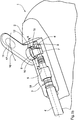
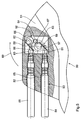
- the pacemaker 1 shown in FIGS. 1a and 1b has a header 2 on, in which a connection socket 3 is arranged, via which a coaxial Electrode line 4 using a standardized IS-1 plug 5 with the pacemaker 1 is electrically connected.
- the different pole 6 of the plug 5 plugged into the connector 3 The proximal end of the coaxial electrode line 4 is in a connector receptacle 7, which is provided within the connection socket 3.
- the connector receptacle 7 carries at its the insertion opening for the plug 5 opposite Side a contact element 8.
- the contact element 8 is tongue-shaped and consists of a spring plate.
- the attachment of the contact element 8 is one side on the wall of the connector receptacle 7, preferably by welding, made that the axis of the contact element substantially extends transversely to the longitudinal axis of the connector receptacle 7 or of the connector 5.
- a receptacle 9 designed as an eccentric is arranged in the plug receptacle, which with a bearing journal 10 mounted in the wall of the header 2 a hand lever 11 is connected.
- the diameter of the clamping cam 9 is such chosen that the free end 12 of the contact element 8 on its flank (compare position 13 in FIG. 1d).
- contact element 8 In the resiliently attached to the plug receptacle 7 contact element 8 is a Bore (compare position 14 in Figure 1c) provided through which the differente pole 6 moves when the plug 5 for connecting the coaxial electrode line 4 with the pacemaker 1 inserted into the socket 3 becomes.
- the contact element 8 and the clamping cam 9 form the elements of a locking device 15, which by pivoting the hand lever 11 in the direction of Arrow 16 can be activated and from an open state in which the connector 5 can be pushed into or removed from the connecting socket 3, in the closed state is spent, in which a in the socket 3 located connector 5 against an unwanted, by one in the axial direction effective tensile force component causes sliding out of the connection socket 3 is secured.
- the locking device 15 is in the closed state by the interaction of the eccentric cam with the contact element 8 between generates a clamping force to the different pole 6 and the contact element 8, which fixes the different pole 6 of the plug 5 in the plug receptacle 7.
- the contact element 8 fastened to the plug receptacle 7 has a bore 14 on which has a free cross section when the locking device is open has sufficient size, through which the different pole 6 of the connector can move when it is pushed into the socket.
- the contact element 8 supported on the flank 13 of the eccentric cam reversibly deformed. This deformation (compare the illustration according to the Figures 2c and 2d) causes a non-positive connection between the contact element 8 and the different pole 6 located in the plug receptacle 7 of the plug.
- the respectively existing locking state of the locking device 15 is easy to recognize by the position of the hand lever 11.
- Is the Hand lever essentially transversely to the longitudinal axis of the connecting socket 3 is the Locking device opened.
- a parallel to the longitudinal axis of the connector Extending hand lever points to a closed locking device there.
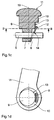
- Figures 2a, 2b, 2c and 2d show the position of the elements 8 and 9 of the locking device 15 if it is in the closed state.
- the hand lever 11 is in the direction of the coaxial electrode line 4 (compare the Position 16 in Figure 1) folded so that it is on the flank 13 of the eccentric cam 9 supporting end 12 of the resilient contact element 8 in the plane of the drawing the respective figure moves to the right, which means that by projection determined on the cross-sectional area of the different pole 6, free diameter of the Hole 14 reduced.
- This causes a sufficiently large clamping action Holding force between different pole 6 and the contact element 8 at an axial Tensile load on the electrode line 4.
- the corresponding tensile force is determined by the Contact element 8 via the plug receptacle 7 or the eccentric cam 9 in the Wall of the header 2 initiated.
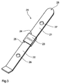
- FIG. 3 shows a contact element made of a metallic spring material 20, which consists of two, electrically insulated from each other connected sections 21 and 22.
- a coupling piece 23 is provided with two insertion pockets 24 and 25, in which one end of each of the sections 21 and 22 is pressed in and / or glued in this way are that the spring and bending properties of the entire contact element 20 of an integral contact element essentially not differentiate.
- the holes 26 and 27 can each have a different pole Take plug of a coaxial electrode line, so that by a rotational movement a clamping sock engaging on the free end 28 of the contact element 20 (Compare position 9 in Figures 1c and 2c) both at the same time Plug in the corresponding connection device against an unwanted Sliding out can be secured.
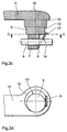
- the pacemaker 30 shown in FIG. 4 has a header 31 with two Connection sockets 32 and 33 for one plug of a coaxial electrode line 34, 35 on.
- the designed as an eccentric cam 36 is located with two, in essentially mirror-symmetrically arranged contact elements 37 and 38 in operative contact.
- the different poles 39, 40 of the plug are by a (Not designated) bore in the respective contact element and are held within this bore by clamping action when the with the eccentric cam 36 on the bearing pin 41 connected hand lever 42 in the direction of Arrow 43 is pivoted.
- connection socket 51 For the pacemaker 5 shown in FIG. 5, there is a header 51 with two Connection sockets 52 and 53 are provided, in each of which the plug one coaxial electrode line 54, 55 is located.
- the different poles 56, 57 of the connector are shown in their position fixed by the respective locking device.
- Plug receptacles 60 and 61 provide a welded connection.
- the contact elements extend parallel to each other.
- 57 fixing locking devices is each of the contact elements 58, 59 assigned an eccentric cam 62, 63, on which the free ends of the Support contact elements 58, 59.
- the eccentric cam 62 is driven indirectly via a pinion 64 when the Eccentric cam 63 rotates when pivoting the hand lever 65.
- the External toothing extends over half the circumference of the journal 66, 67.
Abstract
Description
Die Erfindung betrifft ein implantierbares elektronisches Gerät gemäß dem Oberbegriff des Anspruchs 1.The invention relates to an implantable electronic device according to the preamble of claim 1.
Aus der amerikanischen Patentschrift US-PS 4 540 236 ist eine automatische Verriegelungsvorrichtung für einen Stecker einer mit einem Herzschrittmacher zu verbindenden koaxialen Elektrodenleitung bekannt, bei welcher hakenförmige Halteklauen vorgesehen sind, die in eine an der Steckerspitze vorgesehene Ringnut eingreifen und dadurch eine Sicherung der Steckerverbindung gegen axiale Zugbelastungen bewirken. Um den Stecker aus der Anschlußvorrichtung entfernen zu können, ist eine manuelle Druckeinleitung von der Stirnseite des Headers erforderlich, um über ein Gestänge das Abspreizen der Halteklauen zu bewirken. An automatic is known from the American patent specification US Pat. No. 4,540,236 Locking device for a connector with a pacemaker connecting coaxial electrode line known, in which hook-shaped Holding claws are provided, which are provided in an annular groove provided on the plug tip intervene and thereby secure the connector against axial tensile loads cause. To remove the plug from the connector manual pressure introduction from the front of the header is required, in order to spread the holding claws via a linkage.
Weiterhin ist aus der amerikanischen Patentschrift US-PS 5 252 090 eine selbst
verriegelnde Steckverbindung für den Stecker einer implantierbaren, koaxialen
Elektrodenleitung bekannt, bei der in der Anschlußvorrichtung ein elektrisches
Kontaktelement mit mehreren federnden, im wesentlichen radial nach innen weisenden
Zungen vorgesehen sind, welche durch die Steckerspitze gegen die Federkraft
radial nach außen gedrückt werden und eine Klemmkraft erzeugen, wenn der
Stecker in die Anschlußeinrichtung geschoben wird. Das elektrische Kontaktelement
weist zusätzliche, schräg nach außen gerichtete Federarme auf, durch welche
der Klemmkontakt der nach innen weisenden Zungen an der Steckerspitze aufgehoben
werden kann, wenn diese Federarme von außen durch eine Druckkraft belastet
werden.Furthermore, is from the American patent US-
Darüberhinaus ist gemäß der amerikanischen Patentschrift US-PS 5 697 804 ein Herzschrittmacher mit einer Verriegelungsvorrichtung bekannt, bei welcher das elektrische Kontaktelement als Spiralfeder ausgebildet ist. Durch eine Drehbewegung des Stecker der an den Herzschrittmachers anzuschließend Elektrodenleitung innerhalb der Anschlußvorrichtung ist der Durchmesser der Spiralfeder soweit verringerbar, daß eine Klemmwirkung zwischen den einzelnen Windungen der Spiralfeder und der Mantelfläche des differenten Pol des Steckers erzeugt wird.In addition, according to US Pat. No. 5,697,804 Pacemaker known with a locking device in which the electrical contact element is designed as a spiral spring. By a rotary movement the plug of the electrode lead to be connected to the pacemaker the diameter of the spiral spring is so far within the connecting device reducible that a clamping effect between the individual turns of the Coil spring and the outer surface of the different pole of the connector is generated.
Die bekannten, relativ kompliziert aufgebauten Verriegelungseinrichtungen weisen den Nachteil auf, daß sie bei der Bedienung, insbesondere beim Lösen der Verriegelung, sehr schwer zu handhaben sind, da die Verriegelungseinrichtungen nur durch eine frontal oder seitlich von der Headerwandung manuell einzuleitende Druckkraft gelöst werden können. Darüberhinaus ist in nachteiliger Weise nicht erkennbar, ob der in der Anschlußvorrichtung befindliche Stecker auch wirklich verriegelt worden ist.The known, relatively complicated locking devices have the disadvantage that when it is operated, especially when the lock is released, are very difficult to handle because the locking devices only through a front or side to be initiated manually from the header wall Pressure force can be released. Furthermore, it is not disadvantageous recognizable whether the connector located in the connection device really has been locked.
Letztendlich ist aus der internationalen Patentanmeldung WO98/57702 ein schraubfreies Anschlußsystem für mindestens eine Elektrodenleitung an einen Herzschrittmacher bekannt. An dem Header des Herzschrittmachers ist eine Verriegelungseinrichtung vorgesehen, welche einen mit einer abgesetzten Welle verbundener Handhebel zum Verriegeln einer angeschlossenen Elektrodenleitung aufweist. Die durch den Handhebel verdrehbare Welle erstreckt sich quer zur Achse der für das Einstecken der Elektrodenleitung vorgesehenen Bohrung(en) und weist an ihrem Umfang verteilt sattelförmige Ausnehmungen unterschiedlicher Tiefe auf, welche sich paarweise und orthogonal gegenüberliegen. In Offenstellung der Verriegelungseinrichtung bilden die großen Ausnehmungen der verdrehbaren Welle einen Teil der Bohrungswandung und liegen an der Umhüllung der Elektrodenleitung(en) an. Durch Schwenken des Handhebels gelangen die kleineren Ausnehmungen der Welle unter Verringerung des freien Querschnitts der Bohrung mit der Umhüllung der Elektrodenleitung(en) in Wirkkontakt und blockieren die Elektrodenleitung(en) durch die Klemmwirkung gegen ein axiale Bewegung.Ultimately, from international patent application WO98 / 57702 screwless connection system for at least one electrode line to one Pacemakers known. There is a locking device on the header of the pacemaker provided which one with a stepped shaft connected hand lever for locking a connected electrode lead having. The shaft rotatable by the hand lever extends transversely to Axis of the hole (s) and has saddle-shaped recesses distributed differently around its circumference Depth, which are opposed in pairs and orthogonally. In the open position the locking device form the large recesses of the rotatable Part of the bore wall and lie on the sheath of the electrode line (s) on. The smaller ones reach by swiveling the hand lever Recesses in the shaft while reducing the free cross section of the bore in active contact with the covering of the electrode line (s) and block the Electrode line (s) due to the clamping effect against axial movement.
Diese Verriegelungseinrichtung ist als kompliziertes Formteil ausgebildet und weist den weiteren Nachteil auf, daß die Klemmwirkung der Welle zum Halten des oder der Stecker(s) auf den Bereich der Leitungsisolation einer Elektrodenleitung beschränkt ist. Dadurch erfolgt im wesentlichen nur eine mechanische Zugentlastung der Elektrodenleitung, ohne daß die eigentlichen Kontaktstellen zwangsläufig gesichert sein müssen. Somit ist keine Aussage über die Qualität der Kontaktierung möglich, falls der Stecker der Elektrodenleitung den für ihn vorgesehene Kontaktbereich nach dem Einstecken beispielsweise nicht oder nur teilweise erreicht. Darüberhinaus sind in nachteiliger Weise Beschädigungen der Leitungsstränge bzw. ein Kurzschluß zwischen einzelnen Leitungssträngen nicht mit Sicherheit auszuschließen.This locking device is designed as a complicated molded part and has the further disadvantage that the clamping effect of the shaft to hold the or the connector (s) is limited to the area of the line insulation of an electrode line is. This essentially only results in mechanical strain relief the electrode line without the actual contact points necessarily must be secured. So there is no statement about the quality of the contact possible if the plug of the electrode cable has the contact area intended for it after insertion, for example, not or only partially reached. In addition, damage to the wiring harnesses or a short circuit between individual cable runs cannot be excluded with certainty.
Ausgehend von den Mängeln des Standes der Technik liegt der Erfindung deshalb die Aufgabe zugrunde, ein implantierbares elektronisches Gerät der eingangs genannten Gattung mit einer Verriegelungseinrichtung für den Stecker einer mit dem Gerät verbindbaren, koaxialen Elektrodenleitung anzugeben, durch welche mit einfachen Mitteln ein Fixation des eingesteckten Steckers bei einer auf die Elekrodenleitung wirkenden, im wesentlichen axial gerichteten, Zugbelastung erreichbar ist und gleichzeitig mit Sicherheit eine gute Kontaktierung erfolgt.Based on the shortcomings of the prior art, the invention therefore lies the task is based on an implantable electronic device mentioned type with a locking device for the plug one with to specify the device connectable, coaxial electrode line through which with simple means of fixing the plug in place on the electrode lead acting, essentially axially directed, tensile load achievable and at the same time there is certainly good contact.
Die Aufgabe wird durch die im Anspruch 1 angegebenen Merkmale gelöst.The object is achieved by the features specified in claim 1.
Die Erfindung schließt die Erkenntnis ein, daß bei Einsatz eines exzentrischen, durch einen Hebel eines manuell aktivierbaren Kurbeitriebs aufgrund der Hebelwirkung bereits bei einer relativ geringen Schwenkbewegung durch den Exzenter eine große Kraftwirkung erreichbar ist, welche bevorzugt zur Erzeugung von Klemmkräften zwischen zwei Körpern genutzt werden kann. Durch Wahl der Exzentrizität und die Form des Exzenters ist eine bequeme Dosierung der erzeugten Klemmkraft in Abhängigkeit von der Größe des Schwenkwinkels möglich.The invention includes the finding that when using an eccentric, by a lever of a manually activated spa operation due to the leverage even with a relatively small swivel movement through the eccentric great force effect can be achieved, which is preferred for generating clamping forces can be used between two bodies. By choosing the eccentricity and the shape of the eccentric is a convenient dosage of the clamping force generated possible depending on the size of the swivel angle.
Erfindungsgemäß weist die im Header eines implantierbaren elektronischen Geräts, bevorzugt eines Herzschrittmachers, angeordnete, im wesentlichen buchsenförmige Anschlußvorrichtung für den Stecker einer koaxiale Elektrodenleitung eine Verriegelungseinrichtung auf, welche aus einer manuell betätigbaren, exzentrisch gelagerten Spannocke und einem in der Anschlußvorrichtung vorgesehenen Kontaktelement für den differenten Pol des Steckers einer mit dem Herzschrittmacher zu verbindenden koaxialen Elektrodenleitung gebildet ist.According to the invention, in the header of an implantable electronic device, preferably a cardiac pacemaker, arranged, essentially socket-shaped Connection device for the plug of a coaxial electrode line a locking device on which consists of a manually operated, eccentric stored clamping cam and a contact element provided in the connecting device for the different pole of the plug one with the pacemaker coaxial electrode line to be connected is formed.
Die exzentrisch gelagerte Spannocke steht an ihrem Rand mit dem Kontaktelement in Wirkungseingriff, so daß eine Drehbewegung der Spannocke auf das Kontaktelement übertragen wird. Dadurch wird das den differenten Pol des Steckers formschlüssig umgreifende Kontaktelement derart reversibel verformt, daß zwischen dem differenten Pol und dem Kontaktelement eine kraftschlüssige Verbindung entsteht, welche den Stecker innerhalb der Anschlußvorrichtung fixiert und gleichzeitig einen verbesserten galvanischen Kontakt zwischen dem Kontaktelement und dem differentenn Pol des Steckers sichert.The eccentrically mounted clamping cam is on its edge with the contact element in operative engagement, so that a rotary movement of the clamping cam on the contact element is transmitted. This will make it the different pole of the connector form-fitting encompassing contact element so reversibly deformed that between the different pole and the contact element a non-positive connection arises, which fixes the plug within the connection device and at the same time an improved galvanic contact between the contact element and the differentenn pole of the connector.
Entsprechend der bevorzugten Ausführungsform der Erfindung ist das Kontaktelement an der Steckeraufnahme der Anschlußvorrichtung durch Schweißen befestigt. Das aus einem Federmaterial bestehende Kontaktelement ist zungenförmig ausgebildet und erstreckt sich im wesentlichen quer zur Längsachse der Anschlußvorrichtung. Es weist eine Bohrung auf, durch welche der differente Pol des in der Anschlußvorrichtung befindlichen Steckers geführt ist.According to the preferred embodiment of the invention, the contact element on the plug receptacle of the connection device by welding attached. The contact element consisting of a spring material is tongue-shaped formed and extends substantially transversely to the longitudinal axis of the Connecting device. It has a hole through which the different pole of the connector located in the connector is guided.
Nach der bevorzugten Ausführungsform der Erfindung ist die exentrisch gelagerte Spannocke im wesentlichen scheibenförmig ausgebildet, unter Verwendung eines Lagerzapfens im Header gelagert und mit dem an der Seitenwandung des Headers angeordneten Handhebel zum Erzeugen einer Drehbewegung verbunden.According to the preferred embodiment of the invention, the is eccentrically mounted Spannock formed essentially disc-shaped, using a Bearing journal stored in the header and with that on the side wall of the header arranged hand lever connected to generate a rotary movement.
Die Drehachse der exzentrisch gelagerten Spannocke erstreckt sich im wesentlichen senkrecht zur Achse des Steckers des Elektrodenleitung, so daß sich das freie Ende des Kontaktelements auf dem Rand der exzentrisch gelagerten Spannocke abstützt. Da sich der Abstand des Randes in Bezug auf die Drehachse der Spannocke beim Verdrehen ändert, ist das federnd ausgebildete Kontaktelement durch eine mittels Schwenken des Handhebels erzeugte Drehbewegung der Spannocke reversibel verformbar und wird dabei relativ zu dem differenten Pol des Steckers unter Herstellung einer kraftschlüssigen Verbindung, insbesondere einer Klemmverbindung, mit diesem bewegt.The axis of rotation of the eccentrically mounted clamping cam extends essentially perpendicular to the axis of the plug of the electrode line, so that the free End of the contact element on the edge of the eccentrically mounted clamping cam supports. Because the distance of the edge with respect to the axis of rotation of the clamping cam changes when twisting, the resilient contact element is through a rotary movement of the clamping cam generated by pivoting the hand lever reversibly deformable and becomes relative to the different pole of the connector producing a non-positive connection, in particular a clamp connection, moved with this.
Diese kraftschlüssige Verbindung entsteht auf einfache Weise dadurch, daß sich der durch Projektion auf die Querschnittsfläche des differenten Pols bestimmte, freie Durchmesser der in dem Kontaktelement befindlichen Bohrung verringert. Dies bewirkt durch Klemmwirkung bereits bei relativ geringer Auslenkung des Kontaktelements eine ausreichend große Haltekraft zwischen differentem Pol und dem Kontaktelement zum Fixieren des Steckers bei einer axialen Zugbelastung der koaxialen Elektrodenleitung.This positive connection is created in a simple manner by the fact that the one determined by projection onto the cross-sectional area of the different pole, free diameter of the bore located in the contact element is reduced. This caused by clamping action with a relatively small deflection of the contact element a sufficiently large holding force between the different pole and the Contact element for fixing the connector in the event of an axial tensile load on the coaxial electrode lead.
Entsprechend der bevorzugten Ausführungsform der Erfindung weist die exzentrisch gelagerte Spannocke im wesentlichen die Form einer Kreisscheibe auf, wodurch die Erzeugung einer besonders gleichförmigen Klemmkraft ermöglicht wird. Gleichzeitig ist durch die Verwendung des Handhebels der Kraftaufwand für die Erzeugung der zum Fixieren des Steckers erforderlichen Klemmkraft relativ gering.According to the preferred embodiment of the invention, the has eccentric stored clamping cam essentially in the form of a circular disk, which enables the generation of a particularly uniform clamping force becomes. At the same time, the effort required for using the hand lever the generation of the clamping force required to fix the connector relatively low.
Somit kann die Verriegelung des Steckers einer koaxialen Elektrodenleitung in einem zu implantierenden Herzschrittmacher sehr bequem gehandhabt werden, was beispielsweise unter Operationsbedingungen von einem besonderen Vorteil ist.Thus, the locking of the plug of a coaxial electrode line in a pacemaker to be implanted can be handled very comfortably, what is of particular advantage, for example, under operating conditions.
In einer vorteilhaften Weiterbildung der Erfindung ist vorgesehen, daß das Kontaktelement zum Erzeugen der Klemmwirkung durch reversibles Verformen mittels der exzentrisch gelagerten Spannocke aus einem entspannten Zustand in einen gespannten Zustand überführt wird.In an advantageous development of the invention it is provided that the contact element to generate the clamping effect by reversible deformation using the eccentrically mounted tensioning cam from a relaxed state to a tensioned one Condition is transferred.
Da für die Spannocke entsprechend einer Variante der Erfindung ein Drehbereich von bevorzugt 90° vorgesehen ist, befindet sich der zum Bedienen der Verriegelungseinrichtung an der Außenseite des Headers angeordnete, mit der Spannocke verbundene Handhebel in einer zur Achse der Anschlußvorrichtung im wesentlichen senkrechten Position, wenn die Verriegelungseinrichtung geöffnet wird. Bei geschlossener Verriegelung erstreckt sich der Handhebel im wesentlichen parallel zur Achse der Anschlußvorrichtung und paßt sich dadurch in einer, insbesondere für die Implantation des Herzschrittmachers, vorteilhaften Weise an die Form des Headers an.As a rotation range for the clamping cam according to a variant of the invention of preferably 90 ° is provided for operating the locking device arranged on the outside of the header, with the tensioning cam connected hand lever in a to the axis of the connecting device essentially vertical position when the locking device is opened. When closed Locking extends the hand lever substantially parallel to Axis of the connecting device and thereby fits in one, especially for the implantation of the pacemaker, advantageously to the shape of the Headers.
Aus der Stellung des Handhebels ist somit auf einfache Weise der jeweilige Verriegelungszustand zu erkennen, was für die praktische Anwendung der erfindungsgemäßen Verriegelungseinrichtung von zusätzlichem Vorteil ist.From the position of the hand lever, the respective locking state is thus simple to recognize what the practical application of the invention Locking device is of additional advantage.
Entsprechend einer anderen vorteilhaften Weiterbildung der Erfindung ist an der Außenseite des Headers und der dem Header zugewandten Seite des freien Endes des Handhebels jeweils ein Rastmittel vorgesehen, welche sich bei geschlossener Verriegelungseinrichtung kraft- und/oder formschlüssig in Eingriff befinden und den Handhebel gegen eine unerwünschte, zum Öffnen der Verriegelungseinrichtung führende Rückbewegung fixieren. Die Rastmittel sind als Ansatz und eine den Ansatz aufnehmende Auskehlung entsprechender Größe ausgebildet.According to another advantageous development of the invention, the Outside of the header and the side of the free end facing the header of the hand lever each provided a locking means, which is when closed Locking device are non-positively and / or positively engaged and the Hand lever against an unwanted to open the locking device fix leading return movement. The locking means are as an approach and one Approach-receiving groove of appropriate size.
Nach einer zusätzlichen Variante der Erfindung ist das Kontaktelement zweiteilig ausgebildet, wobei in jedem der Teilstücke eine Bohrung zur Aufnahme des differenten Pols eines jeweils in einer Anschlußvorrichtung befindlichen Steckers vorgesehen ist. Dadurch ist es auf einfache Weise möglich, mit einer exzentrisch gelagerten Spannocke gleichzeitig für die Stecker zweier Elektrodenleitungen jeweils eine Verriegelungseinrichtung zu bilden.According to an additional variant of the invention, the contact element is in two parts formed, with a bore in each of the sections for receiving the different Poles of a plug located in a connection device is provided. This makes it easy to use an eccentric stored tensioning cam at the same time for the plug of two electrode lines each form a locking device.
Die beiden Teilstücke des Kontaktelements sind durch einen Verbinder aus Kunststoff miteinander gekoppelt, da die Stecker der einzelnen koaxialen Elektrodenleitungen ein unterschiedliches Potential führen und ein Potentialausgleich vermieden werden muß.The two sections of the contact element are made of a plastic connector coupled with each other since the plugs of the individual coaxial electrode lines lead a different potential and avoid equipotential bonding must become.
Entsprechend einer anderen günstigen Ausführungsform der Erfindung ist die exzentrisch gelagerte Spannocke zwischen zwei im wesentlichen gleichartig ausgebildeten, vertikal übereinander positionierten Anschlußvorrichtungen angeordnet. Die an den Anschlußvorrichtungen vorgesehenen Kontaktelemente sind gleichartig ausgebildet und sich stützen jeweils bei im wesentlichen spiegelsymmetrischer Anordnung zwecks Bildung einer Verriegelungsvorrichtung auf dem Spannocke ab. Bei einer über den Handhebel erzeugten Drehbewegung der exzentrisch gelagerten Spannocke führen die Kontaktelemente gleichzeitig eine Schwenkbewegung mit entgegengesetztem Richtungssinn aus, so daß durch eine Handhebelbewegung an beiden differenten Polen die zum Fixieren des entsprechenden Steckers erforderliche Klemmkraft erzeugt werden kann.According to another cheap embodiment of the invention, the eccentrically mounted clamping cam between two essentially the same trained, vertically one above the other arranged connection devices. The contact elements provided on the connection devices are are of the same design and are each based on essentially mirror-symmetrical Arrangement to form a locking device on the From. With a rotary movement generated by the hand lever, the eccentric mounted clamping cam, the contact elements simultaneously perform a swiveling movement with the opposite sense of direction, so that by a hand lever movement on both different poles to fix the corresponding one Plug required clamping force can be generated.
Eine gleichermaßen vorteilhafte Betätigung von zwei Verriegelungseinrichtungen ist nach einer zusätzlichen Ausführungsform der Erfindung erreichbar, wenn für jede Anschlußvorrichtung eine gesonderte, jeweils exzentrisch gelagerte, Spannocke vorgesehen ist, wobei die erste Spannocke eine Verbindung mit einem Handhebel aufweist und die Drehbewegung der ersten Spannocke von diesem kraft- und formschlüssig auf die zweite Spannocke übertragen wird. Zur bequemen Übertragung der Drehbewegung weisen die beiden exzentrisch gelagerten Spannocken jeweils einen Lagerzapfen auf, welcher, zumindest an einem Abschnitt ihrer Peripherie, eine Außenverzahnung trägt.An equally advantageous actuation of two locking devices is according to an additional embodiment of the invention achievable if for each Connection device a separate, each eccentrically mounted, clamping cam is provided, the first tensioning cam being connected to a hand lever has and the rotational movement of the first clamping cam of this force and is positively transferred to the second clamping cam. For convenient transfer the two eccentrically mounted clamping cams indicate the rotational movement each have a bearing journal which, at least on a portion of its periphery, has external teeth.
Nach einer Variante der Erfindung ist zur Übertragung der Drehbewegung eine mittelbare Verbindung zwischen den Spannocken vorgesehen, welche sich bevorzugt durch ein Ritzel realisierbar ist, welches die Lagerzapfen der Spannocken unter Bildung eines Getriebes miteinander verbindet.According to a variant of the invention, a for transmitting the rotary movement indirect connection between the tension cams provided, which is preferred can be realized by a pinion, which the bearing pin of the clamping cam under Formation of a gear connects.
Andere vorteilhafte Weiterbildungen der Erfindung sind in den Unteransprüchen gekennzeichnet bzw. werden nachstehend zusammen mit der Beschreibung der bevorzugten Ausführung der Erfindung anhand der Figuren näher dargestellt. Es zeigen:
- Figur 1a
- eine bevorzugtes Ausführungsform der Erfindung mit geöffneter Verriegelungseinrichtung in einer perspektivischen Seitenansicht,
- Figur 1b
- eine Teilansicht der in Figur 1a gezeigten Ausführungsform der Erfindung bei geöffnetem Header in perspektivischer Darstellung,
- Figur 1c
- die Darstellung der Ansicht eines Schnittes längs der Linie A...A gemäß Figur 1b,
- Figur 1d
- die Darstellung der Ansicht eines Schnittes längs der Linie B...B gemäß Figur 1c,
- Figur 2a
- die in Figur 1a gezeigte Ausführungsform der Erfindung mit geschlossener Verriegelungseinrichtung in einer perspektivischen Seitenansicht,
- Figur 2b
- eine Teilansicht der in Figur 2a gezeigten Ausführungsform der Erfindung bei geöffnetem Header in perspektivischer Darstellung,
- Figur 2c
- die Darstellung der Ansicht eines Schnittes längs der Linie C...C gemäß Figur 2b,
- Figur 2d
- die Darstellung der Ansicht eines Schnittes längs der Linie D...D gemäß Figur 2c,
Figur 3- eine günstige Weiterbildung der Erfindung,
Figur 4- eine andere vorteilhafte Ausführungsform der Erfindung in Darstellung eines Teil-Längsschnittes durch eine Anschlußvorrichtung, sowie
Figur 5- eine vorteilhafte Variante der in
Figur 4 gezeigten Ausführungsform der Erfindung in Darstellung eines Teil-Längsschnittes.
- Figure 1a
- a preferred embodiment of the invention with an opened locking device in a perspective side view,
- Figure 1b
- 1 shows a partial view of the embodiment of the invention shown in FIG.
- Figure 1c
- the representation of the view of a section along the line A ... A according to Figure 1b,
- Figure 1d
- the representation of the view of a section along the line B ... B according to Figure 1c,
- Figure 2a
- the embodiment of the invention shown in Figure 1a with the locking device closed in a perspective side view,
- Figure 2b
- 2 shows a partial view of the embodiment of the invention shown in FIG. 2a with the header open, in a perspective view
- Figure 2c
- the representation of the view of a section along the line C ... C according to Figure 2b,
- Figure 2d
- the representation of the view of a section along the line D ... D according to Figure 2c,
- Figure 3
- a favorable further development of the invention,
- Figure 4
- another advantageous embodiment of the invention in a partial longitudinal section through a connecting device, and
- Figure 5
- an advantageous variant of the embodiment of the invention shown in Figure 4 showing a partial longitudinal section.
Der in den Figuren 1a und 1b gezeigte Herzschrittmacher 1 weist einen Header 2
auf, in welchem eine Anschlußbuchse 3 angeordnet ist, über welche eine koaxiale
Elektrodenleitung 4 mittels eines standardisierten IS-1-Steckers 5 mit dem Herzschrittmacher
1 elektrisch verbunden ist.The pacemaker 1 shown in FIGS. 1a and 1b has a
Der differente Pol 6 des in die Anschlußbuchse 3 eingesteckten Steckers 5 am
proximalen Ende der koaxialen Elektrodenleitung 4 befindet sich in einer Steckeraufnahme
7, welche innerhalb der Anschlußbuchse 3 vorgesehen ist. Die Steckeraufnahme
7 trägt an ihrer der Einstecköffnung für den Stecker 5 gegenüberliegenden
Seite ein Kontaktelement 8. Das Kontaktelement 8 ist zungenförmig ausgebildet
und besteht aus einem Federblech. Die Befestigung des Kontaktelements 8 ist
derart einseitig an der Wandung der Steckeraufnahme 7, bevorzugt durch Verschweißen,
vorgenommen, daß sich die Achse des Kontaktelements im wesentlichen
quer zur Längsachse der Steckeraufnahme 7 bzw. des Steckers 5 erstreckt.The
An der in Erstreckungsrichtung des Kontaktelements 8 angeordneten Wandung der
Steckeraufnahme ist eine als Exzenter ausgebildete Spannocke 9 angeordnet,
welche über einen in der Wandung des Headers 2 gelagerten Lagerzapfen 10 mit
einem Handhebel 11 verbunden ist. Der Durchmesser der Spannocke 9 ist derart
gewählt, daß sich das freie Ende 12 des Kontaktelements 8 auf ihrer Flanke
(vergleiche die Position 13 in Figur 1d) abstützt.On the wall of the
In dem federnd an der Steckeraufnahme 7 befestigten Kontaktelement 8 ist eine
Bohrung (vergleiche die Position 14 in Figur 1c) vorgesehen, durch welche sich der
differente Pol 6 bewegt, wenn der Stecker 5 zum Verbinden der koaxialen Elektrodenleitung
4 mit dem Herzschrittmacher 1 in die Anschlußbuchse 3 eingesteckt
wird.In the resiliently attached to the
Das Kontaktelement 8 und die Spannocke 9 bilden die Elemente einer Verriegelungseinrichtung
15, welche durch Schwenken des Handhebels 11 in Richtung des
Pfeils 16 aktivierbar ist und von einem geöffneten Zustand, in welchem der Stecker
5 in die Anschlußbuchse 3 geschoben bzw. aus dieser abgezogen werden kann, in
den geschlossen Zustand verbracht wird, in welchem ein in der Anschlußbuchse 3
befindlicher Stecker 5 gegen ein unerwünschtes, durch eine in axialer Richtung
wirksame Zugkraftkomponente bewirktes Herausgleiten aus der Anschlußbuchse
3 gesichert ist.The
Befindet sich die Verriegelungseinrichtung 15 im geschlossenen Zustand, wird
durch das Zusammenwirken der Exzenternocke mit dem Kontaktelement 8 zwischen
dem differenten Pol 6 und dem Kontaktelement 8 eine Klemmkraft erzeugt,
welche den differenten Pol 6 des Steckers 5 in der Steckeraufnahme 7 fixiert. The locking
Mit 17 und 18 sind als Ausnehmung bzw. als Ansatz ausgebildete Rastmittel an
der Außenseite des Headers 2 und an der Innenseite des Handhebels 11 bezeichnet.
Die Rastmittel gelangen in Wirkungseingriff, wenn der Handhebel in Richtung
des Pfeils 16 zum Schließen der Verriegelungseinrichtung 15 geschwenkt wird.
Dadurch wird auf einfache Weise sichergestellt, daß der Handhebel in dieser
Stellung gegen eine unerwünschte Rückbewegung fixiert ist.With 17 and 18 are formed as a recess or as an approach locking means
the outside of the
In den Figuren 1c und 1d ist der Aufbau und die Wirkungsweise der aus dem
Kontaktelement 8 und der Exzenternocke 9 gebildeten Verriegelungseinrichtung zu
ersehen.In Figures 1c and 1d, the structure and operation of the from
Das an der Steckeraufnahme 7 befestigte Kontaktelement 8 weist eine Bohrung 14
auf, welche bei geöffneter Verriegelungseinrichtung einen freien Querschnitt
ausreichender Größe aufweist, durch welchen sich der differente Pol 6 des Steckers
bewegen kann, wenn dieser in die Anschlußbuchse geschoben wird. Nach
Schwenken des durch den Lagerzapfen 10 im Header gelagerten Handhebels 11
um die Achse 19, welche sich quer zur Längachse der Anschlußbuchse erstreckt,
wird das sich an der Flanke 13 der Exzenternocke abstützende Kontaktelement 8
reversibel verformt. Diese Verformung (vergleiche die Darstellung gemäß der
Figuren 2c und 2d) bewirkt eine kraftschlüssige Verbindung zwischen dem Kontaktelement
8 und dem in der Steckeraufnahme 7 befindlichen differenten Pol 6
des Steckers.The
Der jeweils vorhandene Verriegelungszustand der Verriegelungseinrichtung 15 ist
auf einfache Weise an der Stellung des Handhebels 11 zu erkennen. Steht der
Handhebel im wesentlichen quer zur Längsachse der Anschlußbuchse 3, ist die
Verriegelungseinrichtung geöffnet. Ein sich parallel zur Längsachse der Anschlußbuchse
erstreckender Handhebel weist auf eine geschlossene Verriegelungseinrichtung
hin.The respectively existing locking state of the
Bedingt durch die Länge des Handhebels 11 ist zur Erzeugung der den Stecker in
der Anschlußbuchse 3 fixierenden Klemmkraft zwischen Kontaktelement 8 und
differentem Pol 6 erforderliche Kraftaufwand relativ gering, was für den praktischen
Anwendungsfall, beispielsweise unter Operationsbedingungen in einer
medizinischen Einrichtung, von Vorteil ist.Due to the length of the
Die Figuren 2a, 2b, 2c und 2d zeigen die Position der Elemente 8 und 9 der Verriegelungseinrichtung
15, wenn sich diese in geschlossenem Zustand befindet.Figures 2a, 2b, 2c and 2d show the position of the
Der Handhebel 11 ist in Richtung der koaxialen Elektrodenleitung 4 (vergleiche die
Position 16 in Figur 1) geklappt, so daß sich das an der Flanke 13 der Exzenternocke
9 abstützende Ende 12 des federnden Kontaktelements 8 in der Zeichnungsebene
der jeweiligen Figur nach rechts bewegt, wodurch sich der durch Projektion
auf die Querschnittsfläche des differenten Pols 6 bestimmte, freie Durchmesser der
Bohrung 14 verringert. Dies bewirkt durch Klemmwirkung eine ausreichend große
Haltekraft zwischen differentem Pol 6 und dem Kontaktelement 8 bei einer axialen
Zugbelastung der Elektrodenleitung 4. Die entsprechende Zugkraft wird über das
Kontaktelement 8 über die Steckeraufnahme 7 bzw. die Exzenternocke 9 in die
Wandung des Headers 2 eingeleitet.The
Figur 3 zeigt ein aus einem metallischen Federmaterial hergestelltes, Kontaktelement
20, welches aus zwei, gegeneinander elektrisch isoliert miteinander
verbundenen Teilstücken 21 und 22 besteht. Zur Verbindung der beiden Teilstücke
ist ein Koppelstück 23 mit zwei Einstecktaschen 24 und 25 vorgesehen, in welche
jeweils ein Ende der Teilstücke 21 und 22 derart eingepreßt und/oder eingeklebt
sind, daß sich die Feder- und Biegeeigenschaften des gesamten Kontaktelements
20 von einem einstückig ausgebildeten Kontaktelement im wesentlichen nicht
unterscheiden. Die Bohrungen 26 und 27 können jeweils einen differenten Pol des
Steckers einer koaxialen Elektrodenleitung aufnehmen, so daß durch eine Drehbewegung
einer an dem freien Ende 28 des Kontaktelements 20 angreifenden Spannockes
(vergleiche die Position 9 in den Figuren 1c und 2c) gleichzeitig beide
Stecker in der entsprechenden Anschlußvorrichtung gegen ein unerwünschtes
Herausgleiten gesichert werden können.FIG. 3 shows a contact element made of a
Der in Figur 4 gezeigte Herzschrittmacher 30 weist einen Header 31 mit zwei
Anschlußbuchsen 32 und 33 für jeweils einen Stecker einer koaxialen Elektrodenleitung
34, 35 auf.The
Der als Exzenternocke ausgebildete Spannocke 36 befindet sich mit zwei, im
wesentlichen spiegelsymmetrisch zueinander angeordneten Kontaktelementen 37
und 38 in Wirkkontakt. Die differenten Pole 39, 40 der Stecker sind durch eine
(nicht bezeichnete) Bohrung in dem jeweiligen Kontaktelement geführt und werden
innerhalb dieser Bohrung durch Klemmwirkung gehalten, wenn der mit der Exzenternocke
36 über den Lagerzapfen 41 verbundene Handhebel 42 in Richtung des
Pfeils 43 geschwenkt wird.The designed as an
Durch die in Figur 4 im entriegelten Zustand dargestellte Konstruktion können in
vorteilhafter Weise mit einer Schwenkbewegung des Handhebels 42 gleichzeitig
zwei Stecker gegen unbeabsichtigtes Lösen aus den Anschlußbuchsen 32, 33
gesichert werden.Due to the construction shown in FIG. 4 in the unlocked state, in
advantageously with a pivoting movement of the
Für den in Figur 5 gezeigten Herzschrittmacher 5 ist ein Header 51 mit zwei
Anschlußbuchsen 52 und 53 vorgesehen, in welchen sich jeweils der Stecker einer
koaxiale Elektrodenleitung 54, 55 befindet. Die differenten Pole 56, 57 der Stecker
sind in ihrer durch die jeweilige Verriegelungseinrichtung fixierten Position dargestellt.For the
Zur Verbindung der elektrischen Kontaktelemente 58 und 59 mit der jeweiligen
Steckeraufnahme 60 und 61 ist eine Schweißverbindung vorgesehen. Die Kontaktelemente
erstrecken sich parallel zueinander. Zur Bildung der die differenten Pole
56, 57 fixierenden Verriegelungseinrichtungen ist jedem der Kontaktelemente 58,
59 eine Exzenternocke 62, 63 zugeordnet, auf welchen sich die freien Enden der
Kontaktelemente 58, 59 abstützen. For connecting the
Die Exzenternocke 62 wird mittelbar über ein Ritzel 64 angetrieben, wenn sich die
Exzenternocke 63 beim Schwenken des Handhebels 65 dreht. Zur Bildung des
entsprechenden Getriebes tragen die Lagerzapfen 66, 67 der Exzenternocken 62,
63 eine Außenverzahnung 68. Zur Sicherung der Getriebefunktion zur Kraftübertragung
durch die Bewegung des Handhebels 65 ist es ausreichend, wenn sich die
Außenverzahnung über den halben Umfang der Lagerzapfen 66, 67 erstreckt.The
Beim Bewegen des Handhebels 65 in Richtung des Pfeils 69 werden die Kontaktelemente
58, 59 von dem Druck der jeweiligen Exzenternocke 62, 63 entlastet.
Dabei schwenkt das Kontaktelement 58 bzw. 59 mit seinem freien Ende in der
Zeichnungsebene geringfügig nach unten bzw. nach oben, wodurch die kraftschlüssige
Verbindung zwischen den Kontaktelementen 58,58 und den differenten
Polen 56,57 aufgehoben wird und der jeweilige Stecker der Elektrodenleitungen
54, 55 bequem aus der Anschlußbuchse 52, 53 gezogen werden kann. Das
Entsperren der beiden Verriegelungseinrichtungen gleichzeitig durch eine einzige
Hebeldrehung um etwa 90°, wobei der entsperrte Zustand der Verriegelungseinrichtungen
durch die im wesentlichen senkrechte Stellung des Handhebels 65 an
der Außenwandung des Headers 51 eindeutig zu erkennen ist.When moving the
Die Fixierung der in den Figuren 4 und 5 gezeigten Handhebel 42 und 65 gegen eine unerwünschte Rückbewegung aus einer die Verriegelungseinrichtungen sperrenden Stellung erfolgt durch (nicht dargestellte) Rastmittel in der Art und Weise, wie in den Ausführungen zu Figur 1b bereits erläutert.The fixation of the hand levers 42 and 65 shown in FIGS. 4 and 5 against an undesirable return movement from one of the locking devices locking position takes place by (not shown) locking means in the manner and Way, as already explained in the explanations for Figure 1b.
Das Fixieren beider Stecker in den Anschlußbuchsen 32, 33 bzw. 52, 53 durch
eine Schwenkbewegung des Handhebels 42 bzw. 65 mit relativ geringem Krafteinsatz
ist für die praktische Anwendung, beispielsweise unter Operationsbedingungen
in einer medizinischen Einrichtung, von besonderem Vorteil.Fixing both plugs in the
Aus Gründen der Übersichtlichkeit wurde in den Figuren 1b, 2b, 4 und 5 von einer
Darstellung der elektrischen Leitungsverbindung von zu den elektronischen Baugruppen
des jeweilgen Herzschrittmachers 1, 30 und 50 abgesehen.1b, 2b, 4 and 5, for reasons of clarity
Representation of the electrical line connection from to the electronic assemblies
of the
Die Erfindung beschränkt sich in ihrer Ausführung nicht auf die vorstehend angegebenen bevorzugten Ausführungsbeispiele. Vielmehr ist eine Anzahl von Varianten denkbar, weiche von der dargestellten Lösung auch bei grundsätzlich anders gearteten Ausführungen Gebrauch macht.The invention is not limited in its implementation to those specified above preferred embodiments. Rather, there are a number of variations conceivable, deviate from the solution shown, even if fundamentally different makes use of any type.
Claims (17)
Applications Claiming Priority (2)
| Application Number | Priority Date | Filing Date | Title |
|---|---|---|---|
| DE19930238A DE19930238A1 (en) | 1999-06-25 | 1999-06-25 | Implantable electronic device |
| DE19930238 | 1999-06-25 |
Publications (3)
| Publication Number | Publication Date |
|---|---|
| EP1062986A2 true EP1062986A2 (en) | 2000-12-27 |
| EP1062986A3 EP1062986A3 (en) | 2004-01-21 |
| EP1062986B1 EP1062986B1 (en) | 2006-04-05 |
Family
ID=7913234
Family Applications (1)
| Application Number | Title | Priority Date | Filing Date |
|---|---|---|---|
| EP00250205A Expired - Lifetime EP1062986B1 (en) | 1999-06-25 | 2000-06-23 | Implantable electronic device with connecting and locking devices |
Country Status (4)
| Country | Link |
|---|---|
| US (1) | US6312297B1 (en) |
| EP (1) | EP1062986B1 (en) |
| AT (1) | ATE322306T1 (en) |
| DE (2) | DE19930238A1 (en) |
Cited By (6)
| Publication number | Priority date | Publication date | Assignee | Title |
|---|---|---|---|---|
| EP2477690A1 (en) * | 2009-09-15 | 2012-07-25 | Deringer-Ney, Inc. | Electrical connection system and method for implantable medical devices |
| US8494636B2 (en) | 2011-03-29 | 2013-07-23 | Greatbatch Ltd. | Feed-through connector assembly for implantable pulse generator and method of use |
| US8738141B2 (en) | 2011-04-07 | 2014-05-27 | Greatbatch, Ltd. | Contact assembly for implantable pulse generator and method of use |
| US9112325B2 (en) | 2006-11-15 | 2015-08-18 | Biotronik Crm Patent Ag | Contact configuration, contact assembly, implantable apparatus and electrode line |
| US9138586B2 (en) | 2012-01-27 | 2015-09-22 | Greatbatch Ltd. | Contact block using spherical electrical contacts for electrically contacting implantable leads |
| US9931513B2 (en) | 2011-03-29 | 2018-04-03 | Nuvectra Corporation | Feed-through connector assembly for implantable pulse generator and method of use |
Families Citing this family (12)
| Publication number | Priority date | Publication date | Assignee | Title |
|---|---|---|---|---|
| US6390843B1 (en) * | 2001-06-22 | 2002-05-21 | Pacesetter, Inc. | Lead lock for implantable medical device |
| US20060089681A1 (en) * | 2004-10-21 | 2006-04-27 | Cameron Health, Inc. | Implantable medical device |
| US8206175B2 (en) * | 2007-05-03 | 2012-06-26 | Deringer-Ney, Inc. | Visual indicator of proper interconnection for an implanted medical device |
| CA2646037C (en) | 2007-12-11 | 2017-11-28 | Tyco Healthcare Group Lp | Ecg electrode connector |
| USD737979S1 (en) | 2008-12-09 | 2015-09-01 | Covidien Lp | ECG electrode connector |
| EP2384788B1 (en) | 2010-05-04 | 2012-09-26 | Sorin CRM SAS | Screwless system for quick connection of a probe connector to a generator of an implantable medical device |
| CN103687537B (en) | 2011-07-22 | 2016-02-24 | 柯惠有限合伙公司 | Ecg electrode connector |
| USD771818S1 (en) | 2013-03-15 | 2016-11-15 | Covidien Lp | ECG electrode connector |
| US9408546B2 (en) | 2013-03-15 | 2016-08-09 | Covidien Lp | Radiolucent ECG electrode system |
| EP2967396B1 (en) | 2013-03-15 | 2019-02-13 | Kpr U.S., Llc | Electrode connector with a conductive member |
| US9943685B2 (en) | 2015-04-23 | 2018-04-17 | Cyberonics, Inc. | Lead engagement devices and methods for electrical stimulation and/or monitoring systems |
| WO2018194770A2 (en) * | 2017-04-21 | 2018-10-25 | Medtronic, Inc. | Toolless lead connector assembly |
Citations (4)
| Publication number | Priority date | Publication date | Assignee | Title |
|---|---|---|---|---|
| US4540236A (en) | 1983-07-18 | 1985-09-10 | Cordis Corporation | Quick lock/quick release connector |
| US5252090A (en) | 1992-09-30 | 1993-10-12 | Telectronics Pacing Systems, Inc. | Self-locking implantable stimulating lead connector |
| US5697804A (en) | 1995-01-26 | 1997-12-16 | Pacesetter Ab | Implantable cardiac stimulator having a locking device for releasably retaining a pin-like element of an electrode lead |
| WO1998057702A1 (en) | 1997-06-16 | 1998-12-23 | Medtronic, Inc. | Lead connector system without a setscrew for medical devices |
Family Cites Families (6)
| Publication number | Priority date | Publication date | Assignee | Title |
|---|---|---|---|---|
| US4898173A (en) * | 1988-04-22 | 1990-02-06 | Medtronic, Inc. | In-line pacemaker connector system |
| US5195907A (en) * | 1990-05-31 | 1993-03-23 | Joseph Urban | Tooless electrical connector and conductor cable for use therewith |
| US5261395A (en) * | 1992-03-02 | 1993-11-16 | Cardiac Pacemaker, Inc. | Tooless pulse generator to lead connection |
| US6132390A (en) * | 1996-02-28 | 2000-10-17 | Eupalamus Llc | Handle for manipulation of a stylet used for deflecting a tip of a lead or catheter |
| DE19612756C1 (en) * | 1996-03-29 | 1997-09-11 | Gernot Hirse | Self-clamping tightening spanner with handle joined to clamping lug |
| US5810628A (en) * | 1996-06-21 | 1998-09-22 | General Electric Company | Circuit breaker line and load terminal |
-
1999
- 1999-06-25 DE DE19930238A patent/DE19930238A1/en not_active Withdrawn
-
2000
- 2000-06-23 AT AT00250205T patent/ATE322306T1/en not_active IP Right Cessation
- 2000-06-23 EP EP00250205A patent/EP1062986B1/en not_active Expired - Lifetime
- 2000-06-23 DE DE50012508T patent/DE50012508D1/en not_active Expired - Lifetime
- 2000-06-26 US US09/603,414 patent/US6312297B1/en not_active Expired - Lifetime
Patent Citations (4)
| Publication number | Priority date | Publication date | Assignee | Title |
|---|---|---|---|---|
| US4540236A (en) | 1983-07-18 | 1985-09-10 | Cordis Corporation | Quick lock/quick release connector |
| US5252090A (en) | 1992-09-30 | 1993-10-12 | Telectronics Pacing Systems, Inc. | Self-locking implantable stimulating lead connector |
| US5697804A (en) | 1995-01-26 | 1997-12-16 | Pacesetter Ab | Implantable cardiac stimulator having a locking device for releasably retaining a pin-like element of an electrode lead |
| WO1998057702A1 (en) | 1997-06-16 | 1998-12-23 | Medtronic, Inc. | Lead connector system without a setscrew for medical devices |
Cited By (8)
| Publication number | Priority date | Publication date | Assignee | Title |
|---|---|---|---|---|
| US9112325B2 (en) | 2006-11-15 | 2015-08-18 | Biotronik Crm Patent Ag | Contact configuration, contact assembly, implantable apparatus and electrode line |
| EP2477690A1 (en) * | 2009-09-15 | 2012-07-25 | Deringer-Ney, Inc. | Electrical connection system and method for implantable medical devices |
| EP2477690A4 (en) * | 2009-09-15 | 2013-06-05 | Deringer Ney Inc | Electrical connection system and method for implantable medical devices |
| US8494636B2 (en) | 2011-03-29 | 2013-07-23 | Greatbatch Ltd. | Feed-through connector assembly for implantable pulse generator and method of use |
| US9931513B2 (en) | 2011-03-29 | 2018-04-03 | Nuvectra Corporation | Feed-through connector assembly for implantable pulse generator and method of use |
| US8738141B2 (en) | 2011-04-07 | 2014-05-27 | Greatbatch, Ltd. | Contact assembly for implantable pulse generator and method of use |
| US9492666B2 (en) | 2011-04-07 | 2016-11-15 | Nuvectra Corporation | Contact assembly for implantable pulse generator and method of use |
| US9138586B2 (en) | 2012-01-27 | 2015-09-22 | Greatbatch Ltd. | Contact block using spherical electrical contacts for electrically contacting implantable leads |
Also Published As
| Publication number | Publication date |
|---|---|
| EP1062986A3 (en) | 2004-01-21 |
| DE50012508D1 (en) | 2006-05-18 |
| DE19930238A1 (en) | 2000-12-28 |
| US6312297B1 (en) | 2001-11-06 |
| EP1062986B1 (en) | 2006-04-05 |
| ATE322306T1 (en) | 2006-04-15 |
Similar Documents
| Publication | Publication Date | Title |
|---|---|---|
| EP1062986B1 (en) | Implantable electronic device with connecting and locking devices | |
| EP2367235B1 (en) | Plug for connecting with a socket | |
| WO2001080372A1 (en) | Plug-in connector with a bushing | |
| EP2593994B1 (en) | Housing, in particular for an electrical cable connection | |
| DE102006058680A1 (en) | Electrical connector | |
| WO2019105825A1 (en) | Connection device for the connection of a conductor end | |
| DE69530750T2 (en) | shutter connection | |
| DE102010017361A1 (en) | mounting connectors | |
| WO2020233740A1 (en) | Contact carrier | |
| EP3659217B1 (en) | Contact device | |
| WO2019068287A9 (en) | Locking device of an electric connection device for electric or hybrid motor vehicles | |
| DE102020110647A1 (en) | Primary locking | |
| DE60032856T2 (en) | Holders for modular connectors, in particular for connectors with semiconductor chips and composite connectors | |
| EP3630266B1 (en) | Electromedical adapter, electromedical electrode and electromedical pulse generator | |
| EP0448760A1 (en) | Electrical plug-in connection | |
| AT9874U1 (en) | ELECTRICAL CONNECTION DEVICE | |
| EP3830910A1 (en) | Plug device having lockable components | |
| DE10346367B4 (en) | Freely rotatable HF-angle connector | |
| DE202020005530U1 (en) | Primary locking | |
| EP4150718A1 (en) | Insulating body for screw and crimp contacts | |
| EP1927164A1 (en) | Plug-in connector, bushing contact and locking element | |
| EP3920338A1 (en) | Electrical contact device | |
| DE102022105527A1 (en) | Housing for an electrical connection terminal or an electrical plug connection | |
| EP1047152A2 (en) | Electrical socket | |
| EP3886267A1 (en) | Connector assembly, connector system and method |
Legal Events
| Date | Code | Title | Description |
|---|---|---|---|
| EUG | Se: european patent has lapsed | ||
| PUAI | Public reference made under article 153(3) epc to a published international application that has entered the european phase |
Free format text: ORIGINAL CODE: 0009012 |
|
| AK | Designated contracting states |
Kind code of ref document: A2 Designated state(s): AT BE CH CY DE DK ES FI FR GB GR IE IT LI LU MC NL PT SE |
|
| AX | Request for extension of the european patent |
Free format text: AL;LT;LV;MK;RO;SI |
|
| PUAL | Search report despatched |
Free format text: ORIGINAL CODE: 0009013 |
|
| AK | Designated contracting states |
Kind code of ref document: A3 Designated state(s): AT BE CH CY DE DK ES FI FR GB GR IE IT LI LU MC NL PT SE |
|
| AX | Request for extension of the european patent |
Extension state: AL LT LV MK RO SI |
|
| RIC1 | Information provided on ipc code assigned before grant |
Ipc: 7A 61N 1/375 A Ipc: 7H 01R 4/50 B |
|
| 17P | Request for examination filed |
Effective date: 20040721 |
|
| AKX | Designation fees paid |
Designated state(s): AT BE CH CY DE DK ES FI FR GB GR IE IT LI LU MC NL PT SE |
|
| GRAP | Despatch of communication of intention to grant a patent |
Free format text: ORIGINAL CODE: EPIDOSNIGR1 |
|
| RTI1 | Title (correction) |
Free format text: IMPLANTABLE ELECTRONIC DEVICE WITH CONNECTING AND LOCKING DEVICES |
|
| GRAS | Grant fee paid |
Free format text: ORIGINAL CODE: EPIDOSNIGR3 |
|
| GRAA | (expected) grant |
Free format text: ORIGINAL CODE: 0009210 |
|
| AK | Designated contracting states |
Kind code of ref document: B1 Designated state(s): AT BE CH CY DE DK ES FI FR GB GR IE IT LI LU MC NL PT SE |
|
| PG25 | Lapsed in a contracting state [announced via postgrant information from national office to epo] |
Ref country code: FI Free format text: LAPSE BECAUSE OF FAILURE TO SUBMIT A TRANSLATION OF THE DESCRIPTION OR TO PAY THE FEE WITHIN THE PRESCRIBED TIME-LIMIT Effective date: 20060405 Ref country code: IE Free format text: LAPSE BECAUSE OF FAILURE TO SUBMIT A TRANSLATION OF THE DESCRIPTION OR TO PAY THE FEE WITHIN THE PRESCRIBED TIME-LIMIT Effective date: 20060405 |
|
| REG | Reference to a national code |
Ref country code: GB Ref legal event code: FG4D Free format text: NOT ENGLISH |
|
| REG | Reference to a national code |
Ref country code: CH Ref legal event code: EP |
|
| REG | Reference to a national code |
Ref country code: IE Ref legal event code: FG4D Free format text: LANGUAGE OF EP DOCUMENT: GERMAN |
|
| REF | Corresponds to: |
Ref document number: 50012508 Country of ref document: DE Date of ref document: 20060518 Kind code of ref document: P |
|
| RAP2 | Party data changed (patent owner data changed or rights of a patent transferred) |
Owner name: BIOTRONIK GMBH & CO. KG |
|
| PGFP | Annual fee paid to national office [announced via postgrant information from national office to epo] |
Ref country code: NL Payment date: 20060619 Year of fee payment: 7 |
|
| REG | Reference to a national code |
Ref country code: SE Ref legal event code: TRGR |
|
| PGFP | Annual fee paid to national office [announced via postgrant information from national office to epo] |
Ref country code: FR Payment date: 20060621 Year of fee payment: 7 |
|
| PGFP | Annual fee paid to national office [announced via postgrant information from national office to epo] |
Ref country code: GB Payment date: 20060626 Year of fee payment: 7 |
|
| PGFP | Annual fee paid to national office [announced via postgrant information from national office to epo] |
Ref country code: CH Payment date: 20060627 Year of fee payment: 7 Ref country code: SE Payment date: 20060627 Year of fee payment: 7 |
|
| PG25 | Lapsed in a contracting state [announced via postgrant information from national office to epo] |
Ref country code: MC Free format text: LAPSE BECAUSE OF NON-PAYMENT OF DUE FEES Effective date: 20060630 Ref country code: BE Free format text: LAPSE BECAUSE OF NON-PAYMENT OF DUE FEES Effective date: 20060630 |
|
| PGFP | Annual fee paid to national office [announced via postgrant information from national office to epo] |
Ref country code: IT Payment date: 20060630 Year of fee payment: 7 |
|
| PG25 | Lapsed in a contracting state [announced via postgrant information from national office to epo] |
Ref country code: DK Free format text: LAPSE BECAUSE OF FAILURE TO SUBMIT A TRANSLATION OF THE DESCRIPTION OR TO PAY THE FEE WITHIN THE PRESCRIBED TIME-LIMIT Effective date: 20060705 |
|
| PG25 | Lapsed in a contracting state [announced via postgrant information from national office to epo] |
Ref country code: ES Free format text: LAPSE BECAUSE OF FAILURE TO SUBMIT A TRANSLATION OF THE DESCRIPTION OR TO PAY THE FEE WITHIN THE PRESCRIBED TIME-LIMIT Effective date: 20060716 |
|
| NLT2 | Nl: modifications (of names), taken from the european patent patent bulletin |
Owner name: BIOTRONIK GMBH & CO. KG Effective date: 20060607 |
|
| GBT | Gb: translation of ep patent filed (gb section 77(6)(a)/1977) |
Effective date: 20060712 |
|
| PG25 | Lapsed in a contracting state [announced via postgrant information from national office to epo] |
Ref country code: PT Free format text: LAPSE BECAUSE OF FAILURE TO SUBMIT A TRANSLATION OF THE DESCRIPTION OR TO PAY THE FEE WITHIN THE PRESCRIBED TIME-LIMIT Effective date: 20060905 |
|
| REG | Reference to a national code |
Ref country code: IE Ref legal event code: FD4D |
|
| ET | Fr: translation filed | ||
| PLBE | No opposition filed within time limit |
Free format text: ORIGINAL CODE: 0009261 |
|
| STAA | Information on the status of an ep patent application or granted ep patent |
Free format text: STATUS: NO OPPOSITION FILED WITHIN TIME LIMIT |
|
| 26N | No opposition filed |
Effective date: 20070108 |
|
| PG25 | Lapsed in a contracting state [announced via postgrant information from national office to epo] |
Ref country code: AT Free format text: LAPSE BECAUSE OF NON-PAYMENT OF DUE FEES Effective date: 20060623 |
|
| BERE | Be: lapsed |
Owner name: BIOTRONIK MESS- UND THERAPIEGERATE G.M.B.H. & CO Effective date: 20060630 |
|
| REG | Reference to a national code |
Ref country code: CH Ref legal event code: PL |
|
| EUG | Se: european patent has lapsed | ||
| GBPC | Gb: european patent ceased through non-payment of renewal fee |
Effective date: 20070623 |
|
| NLV4 | Nl: lapsed or anulled due to non-payment of the annual fee |
Effective date: 20080101 |
|
| REG | Reference to a national code |
Ref country code: FR Ref legal event code: ST Effective date: 20080229 |
|
| PG25 | Lapsed in a contracting state [announced via postgrant information from national office to epo] |
Ref country code: CH Free format text: LAPSE BECAUSE OF NON-PAYMENT OF DUE FEES Effective date: 20070630 Ref country code: GR Free format text: LAPSE BECAUSE OF FAILURE TO SUBMIT A TRANSLATION OF THE DESCRIPTION OR TO PAY THE FEE WITHIN THE PRESCRIBED TIME-LIMIT Effective date: 20060706 Ref country code: LI Free format text: LAPSE BECAUSE OF NON-PAYMENT OF DUE FEES Effective date: 20070630 Ref country code: NL Free format text: LAPSE BECAUSE OF NON-PAYMENT OF DUE FEES Effective date: 20080101 |
|
| PG25 | Lapsed in a contracting state [announced via postgrant information from national office to epo] |
Ref country code: GB Free format text: LAPSE BECAUSE OF NON-PAYMENT OF DUE FEES Effective date: 20070623 |
|
| PG25 | Lapsed in a contracting state [announced via postgrant information from national office to epo] |
Ref country code: SE Free format text: LAPSE BECAUSE OF NON-PAYMENT OF DUE FEES Effective date: 20070624 |
|
| PG25 | Lapsed in a contracting state [announced via postgrant information from national office to epo] |
Ref country code: LU Free format text: LAPSE BECAUSE OF NON-PAYMENT OF DUE FEES Effective date: 20060623 |
|
| PG25 | Lapsed in a contracting state [announced via postgrant information from national office to epo] |
Ref country code: FR Free format text: LAPSE BECAUSE OF NON-PAYMENT OF DUE FEES Effective date: 20070702 |
|
| PG25 | Lapsed in a contracting state [announced via postgrant information from national office to epo] |
Ref country code: CY Free format text: LAPSE BECAUSE OF FAILURE TO SUBMIT A TRANSLATION OF THE DESCRIPTION OR TO PAY THE FEE WITHIN THE PRESCRIBED TIME-LIMIT Effective date: 20060405 |
|
| PG25 | Lapsed in a contracting state [announced via postgrant information from national office to epo] |
Ref country code: IT Free format text: LAPSE BECAUSE OF NON-PAYMENT OF DUE FEES Effective date: 20070623 |
|
| REG | Reference to a national code |
Ref country code: DE Ref legal event code: R082 Ref document number: 50012508 Country of ref document: DE Representative=s name: RANDOLL, SOEREN, DIPL.-CHEM. UNIV. DR. RER. NA, DE |
|
| REG | Reference to a national code |
Ref country code: DE Ref legal event code: R081 Ref document number: 50012508 Country of ref document: DE Owner name: BIOTRONIK SE & CO. KG, DE Free format text: FORMER OWNER: BIOTRONIK MESS- UND THERAPIEGERAETE GMBH & CO. INGENIEURBUERO BERLIN, 12359 BERLIN, DE Effective date: 20111219 |
|
| PGFP | Annual fee paid to national office [announced via postgrant information from national office to epo] |
Ref country code: DE Payment date: 20160620 Year of fee payment: 17 |
|
| REG | Reference to a national code |
Ref country code: DE Ref legal event code: R119 Ref document number: 50012508 Country of ref document: DE |
|
| PG25 | Lapsed in a contracting state [announced via postgrant information from national office to epo] |
Ref country code: DE Free format text: LAPSE BECAUSE OF NON-PAYMENT OF DUE FEES Effective date: 20180103 |