EP1065545A1 - Optical fiber cable - Google Patents
Optical fiber cable Download PDFInfo
- Publication number
- EP1065545A1 EP1065545A1 EP00305224A EP00305224A EP1065545A1 EP 1065545 A1 EP1065545 A1 EP 1065545A1 EP 00305224 A EP00305224 A EP 00305224A EP 00305224 A EP00305224 A EP 00305224A EP 1065545 A1 EP1065545 A1 EP 1065545A1
- Authority
- EP
- European Patent Office
- Prior art keywords
- optical fiber
- fiber cable
- fibers
- bundle
- outer sheath
- Prior art date
- Legal status (The legal status is an assumption and is not a legal conclusion. Google has not performed a legal analysis and makes no representation as to the accuracy of the status listed.)
- Granted
Links
Images


Classifications
-
- G—PHYSICS
- G02—OPTICS
- G02B—OPTICAL ELEMENTS, SYSTEMS OR APPARATUS
- G02B6/00—Light guides; Structural details of arrangements comprising light guides and other optical elements, e.g. couplings
- G02B6/44—Mechanical structures for providing tensile strength and external protection for fibres, e.g. optical transmission cables
- G02B6/4401—Optical cables
- G02B6/441—Optical cables built up from sub-bundles
- G02B6/4411—Matrix structure
-
- G—PHYSICS
- G02—OPTICS
- G02B—OPTICAL ELEMENTS, SYSTEMS OR APPARATUS
- G02B6/00—Light guides; Structural details of arrangements comprising light guides and other optical elements, e.g. couplings
- G02B6/44—Mechanical structures for providing tensile strength and external protection for fibres, e.g. optical transmission cables
- G02B6/4401—Optical cables
- G02B6/4403—Optical cables with ribbon structure
-
- G—PHYSICS
- G02—OPTICS
- G02B—OPTICAL ELEMENTS, SYSTEMS OR APPARATUS
- G02B6/00—Light guides; Structural details of arrangements comprising light guides and other optical elements, e.g. couplings
- G02B6/44—Mechanical structures for providing tensile strength and external protection for fibres, e.g. optical transmission cables
- G02B6/4401—Optical cables
- G02B6/4429—Means specially adapted for strengthening or protecting the cables
- G02B6/443—Protective covering
Definitions
- the present invention relates to an optical fiber cable having an improved capability for isolating the fibers from external stresses which can result in optical transmission losses or stress corrosion leading to fiber fracture.
- Optical fibers are composed of very thin strands of pure silica or glass, and they can be characterized as perfectly elastic-brittle in their mechanical behavior.
- a protective material such as a thick layer of a rapidly curing polymeric material.
- the coated optical fibers may be surrounded with a buffer material, such as expanded PTFE which may be bonded to the coated optical fiber.
- HFC high fiber count
- an optical fiber cable which comprises one or more compliant core units enclosed within a Supporting outer sheath.
- Each of the compliant core units comprises at least one optical fiber enclosed in and supported by a compliant unitizing structure.
- a compliant unitizing structure may be constructed from a highly expanded polymeric foam, or a material having an elastic response substantially the same as that of a highly expanded polymeric foam.
- the core units are retained in the outer sheath under a compressive deformation, but so as to permit relative movement therebetween.
- the elastic response of the foam as employed with the present invention is characterized by a nearly constant, relatively low stress for compressive strains up to about
- each of the compliant core units comprises a bundle of parallel optical fibers, such as a ribbon or linear array of multiple fibers.
- FIGS 1-2 illustrate an optical fiber cable 10 which embodies the present invention, and which comprises three compliant core units 20, retained within a conventional outer sheath 30.
- Each compliant core unit 20 is composed of a bundle of parallel optical glass fibers 22, which in the illustrated embodiment is composed of six stacked ribbons 24, with six optical fibers arranged in a laterally aligned array in each ribbon. More particularly, the six fibers of each ribbon are coated with a conventional matrix, such as an acrylate-based material, to form an integral structure.
- the number of fibers per ribbon, ribbons per core unit, and core units per cable are not restricted to that shown in the figures.
- the fibers 22 are of a size commonly used in optical fiber cables, and typically have a diameter of about 250 ⁇ m (microns).
- Each stack of ribbons is enclosed in and supported by a compliant unitizing structure, embodied here as a highly expanded (and thus low density) polymeric foam 26, which sufficiently cushions the fibers from external stresses that are applied when the cable is bent or encounters compressive loading.
- the unitizing structure serves to hold the ribbons in their stacked relation, and no adhesive or the like is required to hold the ribbons together.
- the core i.e. the fibers or ribbons, may be retained under compression by the unitizing structure, but are not otherwise secured to the unitizing structure or each other. Thus the fibers and/or ribbons comprising the core are free to move relative to the unitizing structure and relative to each other.
- the core may be straight or stranded within the Unitizing structure.
- the foam comprising the unitizing structure may be extruded about the stack of ribbons, utilizing well known extrusion equipment and techniques.
- the outer surrounding sheath 30 may comprise any conventional cable construction which may include a core tube, armor, strength members, rods, tapes, rovings, ripcords, and outer jackets, all as known in the art.
- the flexural properties of such a construction will generally exceed those of the fibers or ribbons.
- the relatively low compliance of the unitizing structure effectively decouples the core from the sheath. Consequently, there is not a one-to-one kinematic coupling of flexural displacement between the core and sheath.
- the core units may be retained under compression by the outer sheath, note Figure 2, but the core units are not otherwise secured to the outer sheath or each other. Thus the core units are free to move relative to the outer sheath and relative to each other. Also, the core units may be straight (as illustrated) or stranded within the outer sheath.
- the outer sheath comprises three distinct concentric layers, which may for example comprise an inner layer composed of a polymeric core tube, an intermediate layer composed of strength members and/or armor, and an outer layer composed of a polymer jacket. Also, as best seen in Figure 2, a void may be formed between the units and the outer sheath, as indicated at 40, and the outer sheath retains the core units under a compressive deformation.
- unitizing structure exhibits large deformations for relatively low loading. While a unitizing structure which includes a foamed material as further described herein is preferred since it represents a readily achievable realization of this concept, other structures are possible. From basic principles of solid mechanics, it is well established that stiffness is a result of both the structure's geometry and the material. A solid structure made from a near-incompressible material such as rubber will not produce the desired load-deformation characteristics. However, if structural features that can buckle are incorporated (such as ribs, fins, pins, beams, fingers, membranes, etc.) then a near-incompressible linear elastic material could be used. The key is to create a design with the desired post-buckling load-deformation characteristics. In the case of a foamed material, the structural features that buckle and collapse are fabricated on a microscopic scale, in the form of the cell walls and membranes created during the foaming process.
- the foamed material cell size should be sufficiently small relative to the characteristic geometry of the fibers in order to achieve near uniform load transfer between the fiber and foam material.
- the cell size spacing should also be of a sufficiently random nature, or else be a non-harmonic length with respect to the fiber transmission process in order that the locations of micro-contact not create optical loss based on microbending induced by the periodic loading.
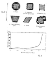
- Figure 4 illustrates a plot of compression stress versus strain that is typical of the desired foam behavior.
- small strains ⁇ 0.05
- there is an initial rise that corresponds to small, linear elastic deformations of the cell structures.
- the curve is nearly horizontal for strains as high as 60%, with the nominal stress plateau below 100 psi, depending on the cellular structure and base polymer. As the cells fully collapse and the walls contact each other directly, the curve takes on a sharp upward slope.
- the material must exhibit successful properties over temperature and time.
- the material should also exhibit low strength, so that it is easily removed to expose the ribbons for splicing.
- Figure 3 illustrates some representative shapes the core units can assume.
- the scope of this invention encompassed not only these shapes, but any combinations or derivatives of them as well.
- the round shape represents a straightforward extruded shape that freely allows the stack to be stranded.
- the rectangular shape uses less material, and may have rounded edges.
- the lobed corner design provides extra protection against loss for the corner fibers, while removing unnecessary material on the edges.
- the tiled or interlocking pattern suggests a shape that promotes both fiber loss protection and unit organization within the cable.
- the skewed shape suggests that ribbon patterns other than prismatic stacks are possible, including radially fanned shapes.
- the general optimized shape illustrates the use of irregular shapes and internal voids or fillers to achieve the desired performance.
- a skin may be desired on the exterior of the core units to promote robust handling qualities and enhanced water blocking abilities.
- the goal of the unitizing structure is to provide a compliant suspension of the ribbon stack that conforms to the geometries of both the cable interior and the ribbon stack with relatively low load transmission between the cable and the optical fibers. Consequently, crush resistance is resident in the outer sheath rather than the core unit structure.
- a rigid exo-skeleton on the core unit structure becomes topologically redundant, and in fact offsets fiber density gains by reducing packaging efficiency. Furthermore, a rigid exo-skeleton inhibits access to the fibers for splicing.
- the core units can be compressed within the cable as desired with minimal increase in the fiber contact loads, and hence minimal induction of transmission loss.
- a high compressibility avoids the problems of large hydrostatic stress components encountered with rubber and other near incompressible hyperelastic materials.
- the preferred foam material is a highly expanded (>90%) polymer such as a polyolefin, created by introducing cellular voids within the base polymer.
- a polyolefin such as polyethylene and polypropylene are preferred.
- Such materials and the associated processing equipment are well established in the present manufacturing state of the art.
- the defining requirement of the foamed material is the compressive stress-strain curve.
- the foamed material preferably should exhibit the elastic response shown in Figure 4. Key characteristics are as follows:
- a foam composition consisting of low density polyethylene (LDPE) supplied by Union Carbide under the trade designation DFDA1253, was foamed utilizing CO 2 injection to produce a 2.5X volume expansion. The resulting foamed composition was tested and it exhibited a compressive stress-stain curve which closely duplicated that shown in Figure 4.
- LDPE low density polyethylene
- Finite element computer analysis used the measured foam data to simulate and analyze the assembly of six compliant core units, as shown in Figure 6.
- Figure 5 illustrates a 30% compression deformation for a core unit composed of twelve twelve-fiber ribbons, and a foam composition as described in the above example.
Abstract
Description
- The present invention relates to an optical fiber cable having an improved capability for isolating the fibers from external stresses which can result in optical transmission losses or stress corrosion leading to fiber fracture.
- Optical fibers are composed of very thin strands of pure silica or glass, and they can be characterized as perfectly elastic-brittle in their mechanical behavior. In order to provide the fibers with protection from external stresses which might cause them to fracture, it has been conventional to coat the fibers with a protective material, such as a thick layer of a rapidly curing polymeric material. As noted in U.S. Patent No. 5,675,686 such protective material protects the bare fibers from the stresses incurred during shipping and processing. Also, the coated optical fibers may be surrounded with a buffer material, such as expanded PTFE which may be bonded to the coated optical fiber.
- It is an object of the present invention to provide an improved optical fiber cable in which the novel compliant unitizing structures minimize both the loads transferred to the fibers and the displacements enforced upon the fibers during the processes and loadings of production, handling, and installation of the cable, so as to enable the design of dry core, high fiber count (HFC) cables with minimum optical transmission loss induced by microbending and/or macrobending of the fibers.
- It is also an object to increase fiber packing density for HFC designs by permitting more fibers to be enclosed within a given cable diameter.
- The above and other objects and advantages of the present invention are achieved by the provision of an optical fiber cable which comprises one or more compliant core units enclosed within a Supporting outer sheath. Each of the compliant core units comprises at least one optical fiber enclosed in and supported by a compliant unitizing structure. Such a structure may be constructed from a highly expanded polymeric foam, or a material having an elastic response substantially the same as that of a highly expanded polymeric foam. The core units are retained in the outer sheath under a compressive deformation, but so as to permit relative movement therebetween.
- The elastic response of the foam as employed with the present invention is characterized by a nearly constant, relatively low stress for compressive strains up to about
- In a preferred embodiment, each of the compliant core units comprises a bundle of parallel optical fibers, such as a ribbon or linear array of multiple fibers.
- Some of the objects and advantages of the present invention having been stated, others will appear as the description proceeds, when considered in conjunction with the accompanying drawings, in which:
- Figure 1 is a perspective view of an optical fiber cable which embodies the features of the present invention;
- Figure 2 is an enlarged sectional view taken along line 2-2 in Figure 1;
- Figure 3 illustrates the cross sections of several possible compliant core units suitable for use in the present invention;
- Figure 4 is a compressive stress-strain diagram for a highly expanded polymeric foam of the type used in the present invention;
- Figure 5 illustrates the cross sections of a compliant core unit under a no-load condition and a 30% compression load Condition; and
- Figure 6 is a finite element analysis contour plot of a compliant unitized structure cable cross section and showing minimum principal stress distribution for one of six 0.25" diameter unitized structures compressed within a 0.62" diameter cable sheath.
-
- The present invention now will be described more fully hereinafter with reference to the accompanying drawings, in which preferred embodiments of the invention are shown. This invention may, however, be embodied in many different forms and should not be construed as limited to the embodiments set forth herein; rather, these embodiments are provided so that this disclosure will be thorough and complete, and will fully convey the scope of the invention to those skilled in the art. Like numbers refer to like elements throughout.
- Referring more particularly to the drawings, Figures 1-2 illustrate an optical fiber cable 10 which embodies the present invention, and which comprises three
compliant core units 20, retained within a conventionalouter sheath 30. Eachcompliant core unit 20 is composed of a bundle of parallel optical glass fibers 22, which in the illustrated embodiment is composed of six stackedribbons 24, with six optical fibers arranged in a laterally aligned array in each ribbon. More particularly, the six fibers of each ribbon are coated with a conventional matrix, such as an acrylate-based material, to form an integral structure. The number of fibers per ribbon, ribbons per core unit, and core units per cable are not restricted to that shown in the figures. The fibers 22 are of a size commonly used in optical fiber cables, and typically have a diameter of about 250µm (microns). - Each stack of ribbons is enclosed in and supported by a compliant unitizing structure, embodied here as a highly expanded (and thus low density)
polymeric foam 26, which sufficiently cushions the fibers from external stresses that are applied when the cable is bent or encounters compressive loading. The unitizing structure serves to hold the ribbons in their stacked relation, and no adhesive or the like is required to hold the ribbons together. The core i.e. the fibers or ribbons, may be retained under compression by the unitizing structure, but are not otherwise secured to the unitizing structure or each other. Thus the fibers and/or ribbons comprising the core are free to move relative to the unitizing structure and relative to each other. Also, the core may be straight or stranded within the Unitizing structure. The foam comprising the unitizing structure may be extruded about the stack of ribbons, utilizing well known extrusion equipment and techniques. - The outer surrounding
sheath 30 may comprise any conventional cable construction which may include a core tube, armor, strength members, rods, tapes, rovings, ripcords, and outer jackets, all as known in the art. The flexural properties of such a construction will generally exceed those of the fibers or ribbons. However, the relatively low compliance of the unitizing structure effectively decouples the core from the sheath. Consequently, there is not a one-to-one kinematic coupling of flexural displacement between the core and sheath. The core units may be retained under compression by the outer sheath, note Figure 2, but the core units are not otherwise secured to the outer sheath or each other. Thus the core units are free to move relative to the outer sheath and relative to each other. Also, the core units may be straight (as illustrated) or stranded within the outer sheath. - In the illustrated embodiment, the outer sheath comprises three distinct concentric layers, which may for example comprise an inner layer composed of a polymeric core tube, an intermediate layer composed of strength members and/or armor, and an outer layer composed of a polymer jacket. Also, as best seen in Figure 2, a void may be formed between the units and the outer sheath, as indicated at 40, and the outer sheath retains the core units under a compressive deformation.
- An important feature of the unitizing structure is that it exhibits large deformations for relatively low loading. While a unitizing structure which includes a foamed material as further described herein is preferred since it represents a readily achievable realization of this concept, other structures are possible. From basic principles of solid mechanics, it is well established that stiffness is a result of both the structure's geometry and the material. A solid structure made from a near-incompressible material such as rubber will not produce the desired load-deformation characteristics. However, if structural features that can buckle are incorporated (such as ribs, fins, pins, beams, fingers, membranes, etc.) then a near-incompressible linear elastic material could be used. The key is to create a design with the desired post-buckling load-deformation characteristics. In the case of a foamed material, the structural features that buckle and collapse are fabricated on a microscopic scale, in the form of the cell walls and membranes created during the foaming process.
- On a micro-mechanical scale, the foamed material cell size should be sufficiently small relative to the characteristic geometry of the fibers in order to achieve near uniform load transfer between the fiber and foam material. The cell size spacing should also be of a sufficiently random nature, or else be a non-harmonic length with respect to the fiber transmission process in order that the locations of micro-contact not create optical loss based on microbending induced by the periodic loading.
- On a macro-mechanical scale, the material should exhibit the compression test characteristics classically associated with foams. Figure 4 illustrates a plot of compression stress versus strain that is typical of the desired foam behavior. For small strains (<0.05), there is an initial rise that corresponds to small, linear elastic deformations of the cell structures. With increased loading, the cell walls collapse and buckle, and strain increases to large amounts for minimal increase in load. The curve is nearly horizontal for strains as high as 60%, with the nominal stress plateau below 100 psi, depending on the cellular structure and base polymer. As the cells fully collapse and the walls contact each other directly, the curve takes on a sharp upward slope.
- Additionally, the material must exhibit successful properties over temperature and time. The material should also exhibit low strength, so that it is easily removed to expose the ribbons for splicing.
- Figure 3 illustrates some representative shapes the core units can assume. The scope of this invention encompassed not only these shapes, but any combinations or derivatives of them as well. The round shape represents a straightforward extruded shape that freely allows the stack to be stranded. The rectangular shape uses less material, and may have rounded edges. The lobed corner design provides extra protection against loss for the corner fibers, while removing unnecessary material on the edges. The tiled or interlocking pattern suggests a shape that promotes both fiber loss protection and unit organization within the cable. The skewed shape suggests that ribbon patterns other than prismatic stacks are possible, including radially fanned shapes. The general optimized shape illustrates the use of irregular shapes and internal voids or fillers to achieve the desired performance.
- A skin may be desired on the exterior of the core units to promote robust handling qualities and enhanced water blocking abilities. The goal of the unitizing structure is to provide a compliant suspension of the ribbon stack that conforms to the geometries of both the cable interior and the ribbon stack with relatively low load transmission between the cable and the optical fibers. Consequently, crush resistance is resident in the outer sheath rather than the core unit structure. A rigid exo-skeleton on the core unit structure becomes topologically redundant, and in fact offsets fiber density gains by reducing packaging efficiency. Furthermore, a rigid exo-skeleton inhibits access to the fibers for splicing.
- By selecting a foamed material that has a sufficiently low stress level associated with the flat portion of the curve (Figure 4), the core units can be compressed within the cable as desired with minimal increase in the fiber contact loads, and hence minimal induction of transmission loss. A high compressibility avoids the problems of large hydrostatic stress components encountered with rubber and other near incompressible hyperelastic materials.
- The preferred foam material is a highly expanded (>90%) polymer such as a polyolefin, created by introducing cellular voids within the base polymer. As specific examples, low density Polyethylene and polypropylene are preferred. Such materials and the associated processing equipment are well established in the present manufacturing state of the art. The defining requirement of the foamed material is the compressive stress-strain curve. Specifically, the foamed material preferably should exhibit the elastic response shown in Figure 4. Key characteristics are as follows:
- 1) The curve should exhibit a plateau resulting from cell wall elastic buckling, defined as a region of near constant, low stress (less than 100 psi) for compressive strains as high as 60%. The onset of the plateau should be between 5% and 10% compressive strain.
- 2) There should be no large "snap-over" loads prior to the onset of the plateau; i.e. the stress should increase in a smooth, monotonic, elastic fashion from zero to the plateau level.
- 3) At compression levels above 60%, the stress-strain curve may adopt an increasingly steep upward slope as the cell walls approach full collapse and the foam densifies. The exact slope is not significant.
- 4) It is desired that the entire stress-strain curve shall be elastic, with no permanent set of the material upon removal of the compressive load. However, under some conditions stress relaxation may be found desirable (i.e. for a fixed deflection, the stress decays to zero over time).
- 5) The foam should be highly compressible, as signified by the effective Poisson's ratio terms approaching zero, or the ratio of the shear to bulk moduli approaching two-thirds.
-
- A foam composition consisting of low density polyethylene (LDPE) supplied by Union Carbide under the trade designation DFDA1253, was foamed utilizing CO2 injection to produce a 2.5X volume expansion. The resulting foamed composition was tested and it exhibited a compressive stress-stain curve which closely duplicated that shown in Figure 4.
- Finite element computer analysis used the measured foam data to simulate and analyze the assembly of six compliant core units, as shown in Figure 6.
- Figure 5 illustrates a 30% compression deformation for a core unit composed of twelve twelve-fiber ribbons, and a foam composition as described in the above example.
- Many modifications and other embodiments of the invention will come to mind to one skilled in the art to which this invention pertains having the benefit of the teachings presented in the foregoing descriptions and the associated drawings. Therefore, it is to be understood that the invention is not to be limited to the specific embodiments disclosed and that modifications and other embodiments are intended to be included within the scope of the appended claims. Although specific terms are employed herein, they are used in a generic and descriptive sense only and not for purposes of limitation.
Claims (12)
- An optical fiber cable comprising:at least one compliant core unit comprising at least one optical fiber enclosed in and supported by a unitizing structure having an elastic response substantially the same as that of an expanded polymeric foam, andan outer sheath enclosing and supporting said at least one core unit so as to permit relative movement between the core unit and the outer sheath.
- The optical fiber cable as defined in Claim 1 wherein the elastic response of the unitizing structure is characterized by a nearly constant, relatively low stress for compressive strains approaching 60%.
- The optical fiber cable as defined in Claim 2 wherein said one compliant core unit comprises a bundle of parallel optical fibers.
- The optical fiber cable as defined in Claim 3 wherein said bundle of parallel optical fibers is of rectangular configuration in cross section.
- The optical fiber cable as defined in Claim 3 wherein said unitizing structure is subjected to a compressive deformation by the contact between the core unit and the outer sheath.
- An optical fiber cable comprising:a plurality of compliant core units each comprising a bundle of parallel optical fibers enclosed in and supported by a compliant unitizing structure; said structure being constructed of an expanded polymeric foam material which effectively cushions the bundle of fibers from external stresses that are applied when the cable is bent, andan outer sheath enclosing and supporting said plurality of core units so as to permit relative movement between the core units and the outer sheath.
- The optical fiber cable as defined in Claim 6 wherein said polymeric foam material is selected from the group consisting of polyethylene and polypropylene.
- The optical fiber cable as defined in Claim 6 wherein said polymeric foam material is subjected to a compression deformation by the contact between the core units and the outer sheath.
- The optical fiber cable as defined in Claim 6 wherein said bundle of parallel optical fibers comprises a plurality of stacked ribbons, with each ribbon comprising a row of laterally aligned fibers.
- The optical fiber cable as defined in Claim 9 wherein the stacked ribbons are held to each other solely by said enclosing unitizing structure.
- The optical fiber cable as defined in Claim 9 wherein said stacked ribbons are retained under compression by the unitizing structure but are not otherwise secured to the unitizing structure or each other, and so that the ribbons are free to move relative to the unitizing structure and relative to each other.
- The optical fiber cable as defined in Claim 6 wherein said polymeric foam has an elastic response which is characterized by a nearly constant, relatively low stress for compressive strains up to about 60%.
Applications Claiming Priority (2)
| Application Number | Priority Date | Filing Date | Title |
|---|---|---|---|
| US09/342,435 US6226431B1 (en) | 1999-06-29 | 1999-06-29 | Optical fiber cable |
| US342435 | 1999-06-29 |
Publications (2)
| Publication Number | Publication Date |
|---|---|
| EP1065545A1 true EP1065545A1 (en) | 2001-01-03 |
| EP1065545B1 EP1065545B1 (en) | 2004-09-29 |
Family
ID=23341816
Family Applications (1)
| Application Number | Title | Priority Date | Filing Date |
|---|---|---|---|
| EP00305224A Expired - Lifetime EP1065545B1 (en) | 1999-06-29 | 2000-06-20 | Optical fiber cable |
Country Status (5)
| Country | Link |
|---|---|
| US (1) | US6226431B1 (en) |
| EP (1) | EP1065545B1 (en) |
| JP (1) | JP2001033672A (en) |
| CN (1) | CN1325952C (en) |
| DE (1) | DE60014253T2 (en) |
Cited By (12)
| Publication number | Priority date | Publication date | Assignee | Title |
|---|---|---|---|---|
| EP1286195A2 (en) * | 2001-08-23 | 2003-02-26 | FITEL USA CORPORATION (a Delaware Corporation) | High count optical fiber cable having encased fiber ribbon stack |
| WO2004061866A2 (en) * | 2002-12-19 | 2004-07-22 | Corning Cable Systems Llc | Optical tube assembly having a dry insert and methods of making the same |
| EP1697768A2 (en) * | 2003-09-12 | 2006-09-06 | Corning Cable Systems LLC | Optical tube assembly having a dry insert and methods of making the same |
| US7177507B2 (en) | 2002-12-19 | 2007-02-13 | Corning Cable Systems, Llc | Optical tube assembly having a dry insert and methods of making the same |
| US7254302B2 (en) | 2002-12-19 | 2007-08-07 | Corning Cable Systems, Llc. | Optical tube assembly having a dry insert and methods of making the same |
| US7277615B2 (en) | 2002-12-19 | 2007-10-02 | Corning Cable Systems, Llc. | Fiber optic cable having a dry insert and methods of making the same |
| US7349607B2 (en) | 2001-06-20 | 2008-03-25 | Corning Cable Systems Technology Incorporated | Optical transmission element |
| US7471862B2 (en) | 2002-12-19 | 2008-12-30 | Corning Cable Systems, Llc | Dry fiber optic cables and assemblies |
| US7471861B2 (en) | 2001-06-20 | 2008-12-30 | Corning Cable Systems Llc | Optical transmission element |
| US7693375B2 (en) | 2002-12-19 | 2010-04-06 | Corning Cable Systems Llc | Fiber optic cable having a dry insert |
| EP3591451A1 (en) * | 2018-07-05 | 2020-01-08 | Prysmian S.p.A. | High density optical cables |
| RU2795698C2 (en) * | 2018-07-05 | 2023-05-11 | Призмиан С.П.А. | High density optical cables |
Families Citing this family (32)
| Publication number | Priority date | Publication date | Assignee | Title |
|---|---|---|---|---|
| US6504980B1 (en) * | 1999-09-03 | 2003-01-07 | Alcatel | Highly compact optical fiber communications cable |
| US6594436B2 (en) * | 2001-07-23 | 2003-07-15 | Molex Incorporated | Holding assembly for cross-connected optical fibers between plural fiber ribbons |
| US6749446B2 (en) * | 2001-10-10 | 2004-06-15 | Alcatel | Optical fiber cable with cushion members protecting optical fiber ribbon stack |
| US6847768B2 (en) * | 2002-09-06 | 2005-01-25 | Corning Cable Systems Llc | Optical fiber tube assembly having a plug |
| US7557298B2 (en) * | 2002-10-14 | 2009-07-07 | World Properties, Inc. | Laminated bus bar assembly |
| US7231119B2 (en) * | 2002-12-19 | 2007-06-12 | Corning Cable Systems, Llc. | Dry fiber optic assemblies and cables |
| US6922511B2 (en) * | 2003-03-31 | 2005-07-26 | Corning Cable Systems Llc | Fiber optic assemblies and cables having subunits with a security feature |
| US20040240806A1 (en) * | 2003-05-30 | 2004-12-02 | Lail Jason C. | Fiber optic cable having a binder |
| US6845200B1 (en) | 2003-10-24 | 2005-01-18 | Corning Cable Systems Llc | Fiber optic assemblies, cable, and manufacturing methods therefor |
| US7254303B2 (en) * | 2004-03-23 | 2007-08-07 | Corning Cable Systems, Llc. | Optical tube assembly having a dry insert and methods of making the same |
| JP2006208773A (en) * | 2005-01-28 | 2006-08-10 | Hitachi Cable Ltd | Optical fiber cable |
| US7567739B2 (en) * | 2007-01-31 | 2009-07-28 | Draka Comteq B.V. | Fiber optic cable having a water-swellable element |
| US7599589B2 (en) * | 2005-07-20 | 2009-10-06 | Draka Comteq B.V. | Gel-free buffer tube with adhesively coupled optical element |
| US7515795B2 (en) | 2005-07-20 | 2009-04-07 | Draka Comteq B.V. | Water-swellable tape, adhesive-backed for coupling when used inside a buffer tube |
| US7639915B2 (en) | 2007-06-28 | 2009-12-29 | Draka Comteq B.V. | Optical fiber cable having a deformable coupling element |
| US7724998B2 (en) * | 2007-06-28 | 2010-05-25 | Draka Comteq B.V. | Coupling composition for optical fiber cables |
| US7646952B2 (en) | 2007-06-28 | 2010-01-12 | Draka Comteq B.V. | Optical fiber cable having raised coupling supports |
| US9188755B2 (en) * | 2009-12-23 | 2015-11-17 | Prysmian S.P.A. | Microbundle optical cable |
| US8682123B2 (en) | 2010-07-15 | 2014-03-25 | Draka Comteq, B.V. | Adhesively coupled optical fibers and enclosing tape |
| US9229172B2 (en) | 2011-09-12 | 2016-01-05 | Commscope Technologies Llc | Bend-limited flexible optical interconnect device for signal distribution |
| US9417418B2 (en) | 2011-09-12 | 2016-08-16 | Commscope Technologies Llc | Flexible lensed optical interconnect device for signal distribution |
| US9488788B2 (en) | 2012-09-28 | 2016-11-08 | Commscope Technologies Llc | Fiber optic cassette |
| RU2642523C2 (en) | 2012-09-28 | 2018-01-25 | Тайко Электроникс Юк Лтд. | Method of manufacture and testing of fiber-optic cartridge |
| US9223094B2 (en) | 2012-10-05 | 2015-12-29 | Tyco Electronics Nederland Bv | Flexible optical circuit, cassettes, and methods |
| WO2016020262A1 (en) | 2014-08-05 | 2016-02-11 | Tyco Electronics Uk Ltd. | Tooling and method for manufacturing a fiber optic array |
| JP2017134267A (en) * | 2016-01-28 | 2017-08-03 | 住友電気工業株式会社 | Optical fiber cable |
| WO2018046677A1 (en) | 2016-09-08 | 2018-03-15 | CommScope Connectivity Belgium BVBA | Telecommunications distribution elements |
| US11409068B2 (en) | 2017-10-02 | 2022-08-09 | Commscope Technologies Llc | Fiber optic circuit and preparation method |
| CN113366357A (en) * | 2018-12-06 | 2021-09-07 | 康宁研究与开发公司 | High density optical fiber ribbon cable |
| EP3948382A4 (en) * | 2019-03-29 | 2022-12-07 | Corning Research & Development Corporation | Optical fiber cable with parallel ribbon subunits |
| US11327260B2 (en) | 2019-07-02 | 2022-05-10 | Corning Research & Development Corporation | Foam for optical fiber cable, composition, and method of manufacturing |
| EP4172672A1 (en) | 2020-06-30 | 2023-05-03 | Corning Research & Development Corporation | Foamed tube having free space around ribbon stacks of optical fiber cable |
Citations (5)
| Publication number | Priority date | Publication date | Assignee | Title |
|---|---|---|---|---|
| DE2929968A1 (en) * | 1979-07-24 | 1981-02-12 | Kabel Metallwerke Ghh | Glass optical waveguide fibre - which is continuously covered with foamed polymer and seam:welded metal tube to protect fibre against mechanical stress |
| JPS5657005A (en) * | 1979-10-16 | 1981-05-19 | Nippon Telegr & Teleph Corp <Ntt> | Optical cable unit and its manufacture |
| US5138684A (en) * | 1991-01-14 | 1992-08-11 | W. L. Gore & Associates, Inc. | High-strength isolated core cable |
| EP0752603A1 (en) * | 1995-07-05 | 1997-01-08 | W.L. GORE & ASSOCIATES, INC. | Improvements in or relating to a buffer material for optical signal transmission media |
| EP0874261A2 (en) * | 1997-04-21 | 1998-10-28 | Lucent Technologies Inc. | High density riser and plenum breakout cables for indoor and outdoor cable applications |
Family Cites Families (13)
| Publication number | Priority date | Publication date | Assignee | Title |
|---|---|---|---|---|
| US4082423A (en) * | 1976-08-19 | 1978-04-04 | The United States Of America As Represented By The Secretary Of The Navy | Fiber optics cable strengthening method and means |
| JPS54134449A (en) * | 1978-04-11 | 1979-10-18 | Kokusai Denshin Denwa Co Ltd | Photoofiber submarine cable |
| US4696542A (en) * | 1982-08-17 | 1987-09-29 | Chevron Research Company | Armored optical fiber cable |
| US4504112A (en) * | 1982-08-17 | 1985-03-12 | Chevron Research Company | Hermetically sealed optical fiber |
| US4740053A (en) | 1984-03-29 | 1988-04-26 | British Telecommunications Plc | Sheathed optical fiber cable |
| GB8714640D0 (en) * | 1987-06-23 | 1987-07-29 | Bicc Plc | Optical fibre cables |
| US5062685A (en) | 1989-10-11 | 1991-11-05 | Corning Incorporated | Coated optical fibers and cables and method |
| US5229851A (en) * | 1992-04-02 | 1993-07-20 | Pirelli Cable Corporation | Optical fiber cable with large number of ribbon units containing optical fibers and enclosed in tubes |
| GB2271859B (en) | 1992-10-21 | 1995-10-18 | Northern Telecom Ltd | Optical fibre cable comprising stack of ribbon fibre elements |
| AU1337695A (en) * | 1994-09-15 | 1996-03-29 | W.L. Gore & Associates, Inc. | Large diameter optical signal cable |
| US5777260A (en) | 1995-03-14 | 1998-07-07 | Siemens Aktiengesellschaft | Coaxial cable additionally having at least one light waveguide |
| DE19516970A1 (en) | 1995-05-09 | 1996-11-14 | Siemens Ag | Electric and optical cable filler with max. swelling power if water enters |
| US5905833A (en) * | 1997-07-01 | 1999-05-18 | Lucent Technologies Inc. | Optical fiber cable having an improved filling material within its core |
-
1999
- 1999-06-29 US US09/342,435 patent/US6226431B1/en not_active Expired - Lifetime
-
2000
- 2000-06-20 EP EP00305224A patent/EP1065545B1/en not_active Expired - Lifetime
- 2000-06-20 DE DE60014253T patent/DE60014253T2/en not_active Expired - Fee Related
- 2000-06-28 CN CNB001193317A patent/CN1325952C/en not_active Expired - Fee Related
- 2000-06-29 JP JP2000195739A patent/JP2001033672A/en not_active Abandoned
Patent Citations (5)
| Publication number | Priority date | Publication date | Assignee | Title |
|---|---|---|---|---|
| DE2929968A1 (en) * | 1979-07-24 | 1981-02-12 | Kabel Metallwerke Ghh | Glass optical waveguide fibre - which is continuously covered with foamed polymer and seam:welded metal tube to protect fibre against mechanical stress |
| JPS5657005A (en) * | 1979-10-16 | 1981-05-19 | Nippon Telegr & Teleph Corp <Ntt> | Optical cable unit and its manufacture |
| US5138684A (en) * | 1991-01-14 | 1992-08-11 | W. L. Gore & Associates, Inc. | High-strength isolated core cable |
| EP0752603A1 (en) * | 1995-07-05 | 1997-01-08 | W.L. GORE & ASSOCIATES, INC. | Improvements in or relating to a buffer material for optical signal transmission media |
| EP0874261A2 (en) * | 1997-04-21 | 1998-10-28 | Lucent Technologies Inc. | High density riser and plenum breakout cables for indoor and outdoor cable applications |
Non-Patent Citations (1)
| Title |
|---|
| PATENT ABSTRACTS OF JAPAN vol. 005, no. 115 (P - 072) 24 July 1981 (1981-07-24) * |
Cited By (30)
| Publication number | Priority date | Publication date | Assignee | Title |
|---|---|---|---|---|
| US7471861B2 (en) | 2001-06-20 | 2008-12-30 | Corning Cable Systems Llc | Optical transmission element |
| US7349607B2 (en) | 2001-06-20 | 2008-03-25 | Corning Cable Systems Technology Incorporated | Optical transmission element |
| EP1286195A2 (en) * | 2001-08-23 | 2003-02-26 | FITEL USA CORPORATION (a Delaware Corporation) | High count optical fiber cable having encased fiber ribbon stack |
| EP1286195A3 (en) * | 2001-08-23 | 2004-09-29 | FITEL USA CORPORATION (a Delaware Corporation) | High count optical fiber cable having encased fiber ribbon stack |
| US7236670B2 (en) | 2002-12-19 | 2007-06-26 | Corning Cable Systems, Llc. | Optical tube assembly having a dry insert and methods of making the same |
| US7277615B2 (en) | 2002-12-19 | 2007-10-02 | Corning Cable Systems, Llc. | Fiber optic cable having a dry insert and methods of making the same |
| US7177507B2 (en) | 2002-12-19 | 2007-02-13 | Corning Cable Systems, Llc | Optical tube assembly having a dry insert and methods of making the same |
| US6970629B2 (en) | 2002-12-19 | 2005-11-29 | Corning Cable Systems Llc | Optical tube assembly having a dry insert and methods of making the same |
| US7747117B2 (en) | 2002-12-19 | 2010-06-29 | Corning Cable Systems Llc | Optical tube assembly having a dry insert and methods of making the same |
| US7254302B2 (en) | 2002-12-19 | 2007-08-07 | Corning Cable Systems, Llc. | Optical tube assembly having a dry insert and methods of making the same |
| EP1818704A3 (en) * | 2002-12-19 | 2007-09-05 | Corning Cable Systems LLC | Optical tube assembly having a dry insert and method of making the same |
| US7751666B2 (en) | 2002-12-19 | 2010-07-06 | Corning Cable Systems Llc | Optical tube assembly having a dry insert and methods of making the same |
| US7336873B2 (en) | 2002-12-19 | 2008-02-26 | Corning Cable Systems, Llc. | Optical tube assembly having a dry insert and methods of making the same |
| WO2004061866A3 (en) * | 2002-12-19 | 2004-09-16 | Corning Cable Sys Llc | Optical tube assembly having a dry insert and methods of making the same |
| US7471862B2 (en) | 2002-12-19 | 2008-12-30 | Corning Cable Systems, Llc | Dry fiber optic cables and assemblies |
| WO2004061866A2 (en) * | 2002-12-19 | 2004-07-22 | Corning Cable Systems Llc | Optical tube assembly having a dry insert and methods of making the same |
| CN100456071C (en) * | 2002-12-19 | 2009-01-28 | 康宁光缆系统有限公司 | Optical tube assembly having a dry insert and methods of making the same |
| US7693375B2 (en) | 2002-12-19 | 2010-04-06 | Corning Cable Systems Llc | Fiber optic cable having a dry insert |
| EP1697768A4 (en) * | 2003-09-12 | 2007-05-16 | Corning Cable Sys Llc | Optical tube assembly having a dry insert and methods of making the same |
| EP1697768A2 (en) * | 2003-09-12 | 2006-09-06 | Corning Cable Systems LLC | Optical tube assembly having a dry insert and methods of making the same |
| DE112004002891B4 (en) * | 2004-06-07 | 2017-05-18 | Corning Cable Systems Llc | Optical tube assembly with dry insert |
| US7787727B2 (en) | 2005-07-29 | 2010-08-31 | Corning Cable Systems Llc | Dry fiber optic cables and assemblies |
| US9477057B2 (en) | 2005-07-29 | 2016-10-25 | Corning Optical Communications LLC | Fiber optic cables and assemblies |
| US9482837B2 (en) | 2005-07-29 | 2016-11-01 | Corning Cable Systems Llc | Dry fiber optic cables and assemblies |
| US9494755B2 (en) | 2005-07-29 | 2016-11-15 | Corning Optical Communications LLC | Fiber optic cable assembly |
| US9971101B2 (en) | 2005-07-29 | 2018-05-15 | Corning Optical Communications LLC | Fiber optic cable assembly |
| EP3591451A1 (en) * | 2018-07-05 | 2020-01-08 | Prysmian S.p.A. | High density optical cables |
| US11262516B2 (en) | 2018-07-05 | 2022-03-01 | Prysmian S.P.A. | High density optical cables |
| RU2795698C2 (en) * | 2018-07-05 | 2023-05-11 | Призмиан С.П.А. | High density optical cables |
| US11796750B2 (en) | 2018-07-05 | 2023-10-24 | Prysmian S.P.A. | High density optical cables |
Also Published As
| Publication number | Publication date |
|---|---|
| US6226431B1 (en) | 2001-05-01 |
| JP2001033672A (en) | 2001-02-09 |
| CN1325952C (en) | 2007-07-11 |
| DE60014253D1 (en) | 2004-11-04 |
| CN1279407A (en) | 2001-01-10 |
| EP1065545B1 (en) | 2004-09-29 |
| DE60014253T2 (en) | 2005-11-24 |
Similar Documents
| Publication | Publication Date | Title |
|---|---|---|
| EP1065545B1 (en) | Optical fiber cable | |
| EP1302796B1 (en) | Optical fiber cable with protection system for optical fiber ribbon stack | |
| US7693375B2 (en) | Fiber optic cable having a dry insert | |
| US7050688B2 (en) | Fiber optic articles, assemblies, and cables having optical waveguides | |
| US5751880A (en) | Optical unit for an optical fiber telecommunications cable, and an optical fiber cable including such a unit | |
| US4078853A (en) | Optical communication cable | |
| EP1573377B1 (en) | Optical tube assembly having a dry insert and methods of making the same | |
| US9182566B2 (en) | Optical-fiber cable having a perforated water blocking element | |
| US6389204B1 (en) | Fiber optic cables with strength members and methods of making the same | |
| JP4197948B2 (en) | Fiber optic cable with an optical fiber variant group | |
| EP3929644A1 (en) | Fiber optic cable assembly | |
| JP3329364B2 (en) | Small core ribbon cable with slot | |
| US20050089285A1 (en) | Optical fiber cables | |
| KR0178021B1 (en) | All-dielectric optical fiber cable having enhanced fiber access | |
| US11796750B2 (en) | High density optical cables | |
| US20040190842A1 (en) | Fiber optic assemblies and cables having a security feature | |
| JP7273960B2 (en) | Fiber optic cable with rollable ribbon and central strength member | |
| Schwartz et al. | Fiber cable design and characterization | |
| US20240027714A1 (en) | High Fiber Density Cable with Flexible Optical Fiber Ribbons | |
| WO2007133187A2 (en) | High-density optical fiber slotted cores and slotted core cables | |
| MXPA96002131A (en) | Grooved nucleus plug cable compa |
Legal Events
| Date | Code | Title | Description |
|---|---|---|---|
| PUAI | Public reference made under article 153(3) epc to a published international application that has entered the european phase |
Free format text: ORIGINAL CODE: 0009012 |
|
| AK | Designated contracting states |
Kind code of ref document: A1 Designated state(s): DE FR GB |
|
| AX | Request for extension of the european patent |
Free format text: AL;LT;LV;MK;RO;SI |
|
| 17P | Request for examination filed |
Effective date: 20010620 |
|
| 17Q | First examination report despatched |
Effective date: 20010718 |
|
| AKX | Designation fees paid |
Free format text: DE FR GB |
|
| GRAP | Despatch of communication of intention to grant a patent |
Free format text: ORIGINAL CODE: EPIDOSNIGR1 |
|
| GRAS | Grant fee paid |
Free format text: ORIGINAL CODE: EPIDOSNIGR3 |
|
| GRAA | (expected) grant |
Free format text: ORIGINAL CODE: 0009210 |
|
| AK | Designated contracting states |
Kind code of ref document: B1 Designated state(s): DE FR GB |
|
| REG | Reference to a national code |
Ref country code: GB Ref legal event code: FG4D |
|
| REF | Corresponds to: |
Ref document number: 60014253 Country of ref document: DE Date of ref document: 20041104 Kind code of ref document: P |
|
| ET | Fr: translation filed | ||
| PLBE | No opposition filed within time limit |
Free format text: ORIGINAL CODE: 0009261 |
|
| STAA | Information on the status of an ep patent application or granted ep patent |
Free format text: STATUS: NO OPPOSITION FILED WITHIN TIME LIMIT |
|
| 26N | No opposition filed |
Effective date: 20050630 |
|
| PGFP | Annual fee paid to national office [announced via postgrant information from national office to epo] |
Ref country code: FR Payment date: 20090617 Year of fee payment: 10 |
|
| PGFP | Annual fee paid to national office [announced via postgrant information from national office to epo] |
Ref country code: GB Payment date: 20090625 Year of fee payment: 10 Ref country code: DE Payment date: 20090629 Year of fee payment: 10 |
|
| GBPC | Gb: european patent ceased through non-payment of renewal fee |
Effective date: 20100620 |
|
| REG | Reference to a national code |
Ref country code: FR Ref legal event code: ST Effective date: 20110228 |
|
| PG25 | Lapsed in a contracting state [announced via postgrant information from national office to epo] |
Ref country code: DE Free format text: LAPSE BECAUSE OF NON-PAYMENT OF DUE FEES Effective date: 20110101 |
|
| PG25 | Lapsed in a contracting state [announced via postgrant information from national office to epo] |
Ref country code: FR Free format text: LAPSE BECAUSE OF NON-PAYMENT OF DUE FEES Effective date: 20100630 |
|
| PG25 | Lapsed in a contracting state [announced via postgrant information from national office to epo] |
Ref country code: GB Free format text: LAPSE BECAUSE OF NON-PAYMENT OF DUE FEES Effective date: 20100620 |