EP1065875A2 - Method and apparatus for making a print having an invisible coordinate system - Google Patents
Method and apparatus for making a print having an invisible coordinate system Download PDFInfo
- Publication number
- EP1065875A2 EP1065875A2 EP00202062A EP00202062A EP1065875A2 EP 1065875 A2 EP1065875 A2 EP 1065875A2 EP 00202062 A EP00202062 A EP 00202062A EP 00202062 A EP00202062 A EP 00202062A EP 1065875 A2 EP1065875 A2 EP 1065875A2
- Authority
- EP
- European Patent Office
- Prior art keywords
- image
- coordinate system
- printing
- media
- Prior art date
- Legal status (The legal status is an assumption and is not a legal conclusion. Google has not performed a legal analysis and makes no representation as to the accuracy of the status listed.)
- Withdrawn
Links
Images


Classifications
-
- H—ELECTRICITY
- H04—ELECTRIC COMMUNICATION TECHNIQUE
- H04N—PICTORIAL COMMUNICATION, e.g. TELEVISION
- H04N1/00—Scanning, transmission or reproduction of documents or the like, e.g. facsimile transmission; Details thereof
- H04N1/32—Circuits or arrangements for control or supervision between transmitter and receiver or between image input and image output device, e.g. between a still-image camera and its memory or between a still-image camera and a printer device
- H04N1/32101—Display, printing, storage or transmission of additional information, e.g. ID code, date and time or title
- H04N1/32144—Display, printing, storage or transmission of additional information, e.g. ID code, date and time or title embedded in the image data, i.e. enclosed or integrated in the image, e.g. watermark, super-imposed logo or stamp
-
- H—ELECTRICITY
- H04—ELECTRIC COMMUNICATION TECHNIQUE
- H04N—PICTORIAL COMMUNICATION, e.g. TELEVISION
- H04N2201/00—Indexing scheme relating to scanning, transmission or reproduction of documents or the like, and to details thereof
- H04N2201/32—Circuits or arrangements for control or supervision between transmitter and receiver or between image input and image output device, e.g. between a still-image camera and its memory or between a still-image camera and a printer device
- H04N2201/3201—Display, printing, storage or transmission of additional information, e.g. ID code, date and time or title
- H04N2201/3225—Display, printing, storage or transmission of additional information, e.g. ID code, date and time or title of data relating to an image, a page or a document
-
- H—ELECTRICITY
- H04—ELECTRIC COMMUNICATION TECHNIQUE
- H04N—PICTORIAL COMMUNICATION, e.g. TELEVISION
- H04N2201/00—Indexing scheme relating to scanning, transmission or reproduction of documents or the like, and to details thereof
- H04N2201/32—Circuits or arrangements for control or supervision between transmitter and receiver or between image input and image output device, e.g. between a still-image camera and its memory or between a still-image camera and a printer device
- H04N2201/3201—Display, printing, storage or transmission of additional information, e.g. ID code, date and time or title
- H04N2201/3269—Display, printing, storage or transmission of additional information, e.g. ID code, date and time or title of machine readable codes or marks, e.g. bar codes or glyphs
- H04N2201/327—Display, printing, storage or transmission of additional information, e.g. ID code, date and time or title of machine readable codes or marks, e.g. bar codes or glyphs which are undetectable to the naked eye, e.g. embedded codes
-
- H—ELECTRICITY
- H04—ELECTRIC COMMUNICATION TECHNIQUE
- H04N—PICTORIAL COMMUNICATION, e.g. TELEVISION
- H04N2201/00—Indexing scheme relating to scanning, transmission or reproduction of documents or the like, and to details thereof
- H04N2201/32—Circuits or arrangements for control or supervision between transmitter and receiver or between image input and image output device, e.g. between a still-image camera and its memory or between a still-image camera and a printer device
- H04N2201/3201—Display, printing, storage or transmission of additional information, e.g. ID code, date and time or title
- H04N2201/3271—Printing or stamping
Definitions
- the present invention relates to encoding data onto a pictorial hardcopy print so that when the pictorial hardcopy print is digitally scanned by a scanner for reprinting and/or displaying of the image, the data provided on the print can be used to provide information about the image content and/or provide other informational data.
- a problem with the foregoing disclosures is that in order to provide the informational data on the print which is not visible, digital printing techniques are used at the time of printing of the original print. This suffers from several drawbacks. First, this does not allow the addition of additional information later on. Secondly, while the original image is not distorted at some point, in order to avoid further degradation of the image the amount of information allowed is limited. In addition, this system also requires a scanner or computer techniques for observing of the information encoded in the hardcopy print.
- Applicants have provided an improved method and apparatus wherein information can be put on the hardcopy print at the time of manufacturing of the print, or at some later date, which can be easily read and associated with the image.
- a print containing an image made using a digital printer and a coordinate system separate from the image made by a digital printer on the same side as the image, the coordinate system not being visible to the human eye under normal viewing conditions and capable of locating a specific location on the image.
- a digital printer comprising:
- a media for use in a digital printer having a printing side and a back side, the printing side having a coordinate system printed thereon which is not visible to the human eye under normal viewing conditions.
- a method for printing an image on a media having a pre-printed coordinate system thereon, the pre-printed coordinate system is not visible to the human eye under normal viewing conditions comprising the steps of:
- a digital printer for printing an image onto a media having a pre-printed coordinate system printed thereon, the coordinate system not being visible to the human eye under normal viewing conditions, the printer having means for printing an image on the media, the image having a predetermined relationship with respect to the coordinate system.
- a computer program product comprising a computer readable storage medium having a computer program stored therein which when loaded in a computer will enable a digital printer to perform the step of:
- a hardcopy print 10 made in accordance with the present invention.
- the print 10 includes a digital image 12 placed thereon by a variety of known printing techniques.
- an image may be produced by optically or digitally printing the image 12 on a photosensitive media, for example, photographic paper, photographic film, or maybe printed on any other hardcopy media by any other known printing devices such as inkjet, thermal, LED, CRT, laser, etc.
- print 10 is a photographic print having a color image 12 formed thereon by either a digital or optical printer.
- additional encoded information may be provided thereon, which is undetectable by the viewer.
- this is accomplished by providing a printer, which can print directly on the hardcopy print information not normally visible by a viewer under normal viewing conditions.
- this is obtained by using an infrared ink which is printed on the hardcopy print 10 after the image has been fully formed thereon.
- An example of a suitable ink may be obtained from the Eastman Kodak Company, under the tradename N.I.R.F. (near-infrared fluorophore).
- the information/indicia is printed on the print 10 so as to enable scanning thereon, which contains information that relates it to the image. In order to accomplish such, it is necessary to provide a coordinate system and information to be read.
- print 10 of Fig. 1 illustrating information which is not normally visible in section 18 which can be read by a scanner.
- the information in section 18 typically contains information which relates to the image on print 10.
- print 10 includes a coordinate system 16 which provides a reference whereby certain features/items in the image 12 can be located and identified.
- the coordinate system 16 is also not normally visible by the viewer under normal viewing conditions, but can be scanned by a scanner.
- the information 18 and coordinate system 16 are provided on the same side and directly over the image 12.
- image 12 illustrates two individuals 20,22 in a scene which includes a house 24 and mountains 26,28. Additional information can be provided in machine-readable or human-readable form, which relate to the items in image 12.
- informational section 18 may include the names of the individuals 20,22. Coordinate system 16 allows easy identification of the individuals or other items within the image 12. When the image 12 is scanned by a digital scanner, both the information relating to the image 12 and the information within section 18 is obtained in a single scanning operation.
- information within section 18 may further include a code 32 for identifying the particular type information contained therein, including information stating that the hardcopy print does include encoded information.
- the names of the individuals 20,22, mountains 26,28 and identification of items such as the house 24 can be provided.
- the coordinate system 16 allows the locating and identification of these items, which then can be later visually displayed, for example, on a CRT, or used to produce a second hardcopy print wherein the information is actually placed thereon without affecting or detracting from the visual appearance of the image 12.
- printer 40 capable of printing onto a hardcopy print 10 using an ink, which is not normally visible by a viewer under normal viewing conditions.
- printer 40 is an inkjet printer having a printhead 42 designed to apply any desired image appropriate on the media 43 as it passes therethrough.
- the printhead 42 prints directly over image 12 on print 10, however, since an invisible ink is being applied, the image 12 will be viewed as it would normally be viewed.
- the printer 40 includes an inlet/supply tray 44 for receiving media 43, such as hardcopy print 10, an outlet tray for retaining media that has been passed through the printer, and a printing path along which the photosensitive media passes from supply tray to outlet tray 46.
- the printhead 42 is positioned with respect to the printing path so as to provide printing onto media 43 as it passes thereby.
- An appropriate transport mechanism is provided for transporting of the media from the supply tray 44 along the printing path 14 to outlet tray 46.
- the hardcopy print 10 already has an image formed thereon in which case the informational data and coordinate system 16 is placed thereon by the printer 40.
- the informational data and coordinate system are separate from the image and printed at a different time.
- This information can be inputted in a variety of different manners. For example, the image could have been previously scanned and the information provided to a computer, such as a PC, and an appropriate software program could have been provided for illustrating a grid system and allowing of entry of information with respect to the grid system.
- a mouse or other similar type control unit could have been used to identify certain areas of the image scanned and appropriate data/information can be entered with respect to such location for identifying persons, places, or things, and this information can be stored to a record file, which can be then forwarded over to a printer 40 for printing.
- the information regarding the image can be entered and/or forwarded to the printer 40 by a variety of known techniques, including hardwire connection or by the internet.
- the printer may be provided with a scanner 50, which scans the image prior to reaching the printhead 42 where the printhead provides the image.
- the image on hardcopy print 10 is scanned by the scanner 50 and displayed on display device 52, for example, a CRT or liquid crystal display.
- the printer 40 is controlled by an appropriate computer 54 whereby a super-imposed grid system can be provided over the image scanned and data entry can be entered through keyboard 56, or any other input device.
- the information is appropriately encoded and printed onto the image 12 through the use of printhead 42.
- the hardcopy print 10 leaving the printer 40 at outlet tray 46 will have thereon appropriate encoded information and an orientation system for properly identifying and using said information.
- the information in section 18 may also contain a code which can be read by a scanner which will identify that the hardcopy print 10 is of the type containing such information and the appropriate information necessary for interpreting the information, including the type of reference orientation provided thereon.
- the hardcopy print 10 will allow normal viewing of the image, yet when scanned by an appropriate scanner, will be able to read so as to obtain information not normally visible, which can then later be used for displaying, storing, or producing a hardcopy print which includes such information.
- the ink is such that it cannot be normally viewed by individuals, but is still capable of being read by a digital scanner.
- the scanner 30 may of any type digital scanner, for example, but not by way of limitation, AVISION 630CS, HP Scanjet 5100C, UMAX Powerlook 200, and Epson ES-1200C. Modification of these scanners is necessary to make the scanner to sense the infrared ink not normally visible.
- the infrared blocking filter used to prevent infrared light from being sensed by the imager may be selectively removed when it is desired to scan the infrared record.
- a separate channel for sensing infrared light may be added to the imaging head.
- an infrared light source may need to be added to the scanner.
- any appropriate other digital scanner may be employed.
- FIG. 4 there is illustrated a modified printing apparatus 70 made in accordance with the present invention.
- This apparatus 70 is similar to printing apparatus 40, like numerals indicating like parts and like operation.
- a printhead 72 is provided for printing of a digital image obtained from a digital image file/record onto the media passing thereby along printing path 48.
- the printhead 72 comprises an inkjet printhead, however, it is to be understood that any other desired digital printing system may be employed in place of printhead 72.
- the apparatus 70 includes a second printing system 74, which in the particular embodiment illustrated comprises a digital inkjet printhead 75 similar in operation and construction to printhead 72.
- the printhead 75 produces a orientation grid and data information as previously discussed with respect to printhead 42. A sufficient amount of spacing is provided between the printheads 72,74 such that the ink being applied by one will not substantially affect the ink being applied by the other.
- the present invention is not so limited.
- the location of the printheads 72,75 may be switched in their respective positions such that the invisible ink is placed on the media prior to formation of the customer generated image.
- the image applied by printhead 72 is provided after the application of the information and/or orientation system provided by printhead 75.
- the ink being applied is of such a nature that it can still be observed by a scanner through the image applied by printhead 72.
- An example of a suitable ink used for printing of the customer image is sold by Eastman Kodak Company under the tradename KODAK PROFESSIONAL DYE INKS and an appropriate suitable ink for placement of the information and grid by printhead 72 is sold by Eastman Chemical Company under the tradename N.I.R.F. (near-infrared fluorophore) inks.
- a scanner and output system which may be used to scan a hardcopy print 10 of the type having encoded invisible information as previously discussed.
- the system includes a digital scanner 30, which may be of any digital type as commonly available, for example, but not by way of limitation, a Vision 630CS, HP Scanjet 5100C, Newmax Power Look 200 and Epson ES 1200C.
- the image 12 on the hardcopy print 10 is scanned by scanner 30, thereby the appropriate information regarding the image is obtained as is typically done with prior art scanners.
- the scanner 30, in the embodiment illustrated has been programmed to recognize and read informational data such as provided by section 18 and coordinate system 16.
- the coordinate system 16 is used primarily so that information contained in section 18 can be related to items/objects in the image 12.
- An appropriate computer 49 is provided for interpreting of the data obtained by scanner and is sent forward to an appropriate output device 47.
- the output device 47 may comprise a variety of different digital output devices, for example, but not by way of limitation, various digital type printers, display devices, or storage memory devices whereby the information can then later be retrieved directly or through the internet, or other communication system.
- FIG. 6 there is illustrated an image 12 on a display screen 53 obtained from scanning hardcopy print 10 on scanner 30 wherein information provided in information section 18 is displayed with respect to the objects or persons provided in the image 12.
- the two individuals are identified as Grandma X and Aunt Y, and that the locations provided with respect to the cabin are illustrated therein.
- the output device 47 may include a printer, in which case the image with the annotated information may be printed if so desired.
- FIG. 2 there is illustrated an coordinate system 16 in the form of an unique, symmetrical shape.
- the present invention is not limited to this particular type orientation system.
- Various other orientation system/patterns may be used as desired.
- the principal function of the coordinate system 16 is for providing a reference by which the information contained in section 18 may be associated with the particular items within the image 12.
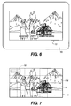
- FIG. 7 there is illustrated a modified hardcopy print 10 made in accordance with the present invention.
- an orientation system 116 in the form of a grid pattern.
- the information section would provide an appropriate code identifying the particular relationship with respect to the grid pattern so that particular items may be identified.
- various other orientation schemes may be used as long as they are able to allow identification of particular locations within the image for locating encoded information in specific areas of the image 12.
- the hardcopy print 10 includes information in machine-readable format.
- the present invention is not so limited.
- a hardcopy print 210 made in accordance with the present invention, like numerals indicating like parts.
- a grid 119 is provided along with informational information in a corner identifying certain objects with respect to the grid. This is particularly useful when the invisible ink being used can be viewed under special viewing conditions. For example, under normal viewing conditions the ink is such that it is not visible to the viewer, however, under ultraviolet light, typically referred to as a black light, the information printed thereon would be visible.
- the information is provided in association with a grid 119, however, since the information can be viewed, the grid 119 may be dispensed with, and the information may be put directly in association therewith. In such situations, the grid 119 may be maintained so that any machine-readable information can still be scanned and associated with the image for later printing and storing of the image 12.
- FIG. 9 there is illustrated a modified form of the present invention illustrating a different way in which the information may be displayed.
- the image scanned is illustrated on a display screen.
- the informational data is placed off to the one side of the image so that the image may be viewed unobstructed, yet also while in viewing the image in the unobstructed view.
- a grid 119 may be optionally placed over the image 12 in the situations where additional information is provided for specific identification of items within the image.
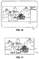
- Fig. 10 is a view similar to Fig. 9 illustrating the image without the grid system.
- FIG. 11 there is illustrated a modified hardcopy print 310 made in accordance with the present invention.
- the hardcopy print 310 is similar to hardcopy 10, like numerals indicating like parts.
- the informational data is printed in the actual location being related to. Thus, in this situation, there is no need to provide a coordinate system.
- the coordinate system 410 is preprinted on the media 400 using an infrared ink.
- the coordinate system 410 can have a specific pattern corresponds to a different type media.
- a grid with lines spaced at 1/8 inch (3.175 mm) intervals can designate thermal media such as KODAK PROFESSIONAL EKTATHERM XLS Print Paper used with a KODAK 8650 PS Color Printer.
- a grid with lines spaced at 1/4 inch (6.35 mm) intervals can designate inkjet media such as KODAK Inkjet Photo Stickers which can be printed on a Hewlett Packard DeskJet 870Cxi.
- the coordinate system 410 can have a specific pattern which corresponds to a specific image type to be placed thereon. For example, a grid with dashed lines can designate an image originated from a digital file, while a grid with solid lines can designate an image originating from an optically captured image.
- a specific pattern may indicate a professionally generated image. Care must be taken to insure the media type corresponding to the type of image being printed is used.
- the printing application can indicate which media is appropriate and refuse to print for improper matches of file type and media. Additionally, in the case of professional images, the grid pattern may indicate ownership of the imagery, and can be used to prevent enabled stations from copying the image and also be used as a means for identifying the material is copyrighted.
- An image is printed on a media 400 having a pre-printed coordinate system 410 such as the grid not being visible to the human eye under normal viewing conditions, by first scanning the media using a scanner 30 (See Fig. 5), or the printer 40 (See Fig. 3) to determine the type and location of the pre-printed coordinate system 410 provided. Then providing an image 12 (See Fig. 1) to be printed which has information 18, such as illustrated in Fig. 8, relating to a particular location on the image which can be defined by the coordinate system and printing the image on the media in accordance with the data with respect to the coordinate system.
- the user may indicate to the printing device which type of media is being used and which type coordinate system is to be applied thereto.
- the media need not be scanned for the invisible printed matter.
- any desired media may be used and any desired digital printing technology may be employed, such as electrophotography or thermal printing.
- the clear top layer of the thermal media may contain the coordinate system.
Abstract
Description
- The present invention relates to encoding data onto a pictorial hardcopy print so that when the pictorial hardcopy print is digitally scanned by a scanner for reprinting and/or displaying of the image, the data provided on the print can be used to provide information about the image content and/or provide other informational data.
- In the prior art it has been suggested providing informational data on the hardcopy print in a manner that is visually indistinguishable from the image. For example, it has been suggested in various patent applications the printing of a hardcopy print using digital printing techniques wherein informational data is embedded in the image. An example is set forth in copending EPO Application No. 962033163.3, filed on November 25, 1996. It has also been suggested in copending, commonly assigned EPO Application No. 99204101.2, filed on December 2, 1999, a means for providing a coordinate system, which is embedded into the digitally formed image, which can be used in relating other informational data that has also been encoded on the print to later printing and/or displaying of the image.
- A problem with the foregoing disclosures is that in order to provide the informational data on the print which is not visible, digital printing techniques are used at the time of printing of the original print. This suffers from several drawbacks. First, this does not allow the addition of additional information later on. Secondly, while the original image is not distorted at some point, in order to avoid further degradation of the image the amount of information allowed is limited. In addition, this system also requires a scanner or computer techniques for observing of the information encoded in the hardcopy print.
- Applicants have provided an improved method and apparatus wherein information can be put on the hardcopy print at the time of manufacturing of the print, or at some later date, which can be easily read and associated with the image.
- In accordance with one aspect of the present invention there is provided a method for making a digital print, comprising the steps of:
- a) obtaining a digital image file containing an image for printing by a digital printer;
- b) printing onto a media using a digital printer on the image; and
- c) printing a coordinate system that is not being visible to the human eye under normal viewing conditions separate from the printing of the image, the coordinate system being capable of locating a specific area of the image on the print.
-
- In accordance with another aspect of the present invention there is provided a method for making a digital print, comprising the steps of:
- a) obtaining a print containing an image; and
- b) printing a coordinate system on the print over the image, the coordinate system is not visible to the human eye under normal viewing conditions and is separate the image, the coordinate system being capable of locating a specific area of the image on the print.
-
- In accordance with yet another aspect of the present invention there is provided a print containing an image made using a digital printer and a coordinate system separate from the image made by a digital printer on the same side as the image, the coordinate system not being visible to the human eye under normal viewing conditions and capable of locating a specific location on the image.
- In accordance with still another aspect of the present invention there is provided a digital printer comprising:
- a first printing mechanism for digitally printing a visible image on a media; and
- a second printing mechanism for digitally printing a coordinate system that is not visible to the human eye under normal viewing conditions on the media.
-
- In another aspect of the present invention there is provided a media for use in a digital printer, the media having a printing side and a back side, the printing side having a coordinate system printed thereon which is not visible to the human eye under normal viewing conditions.
- In accordance with a further aspect of the present invention there is provided a method for printing an image on a media having a pre-printed coordinate system thereon, the pre-printed coordinate system is not visible to the human eye under normal viewing conditions, the method comprising the steps of:
- a) scanning the media so as to determine if the pre-printed coordinate system is provided thereon;
- b) providing an image to be printed on the media which has information specific to a particular location on the image which can be defined by the coordinate system; and
- c) printing an image on the media in accordance with the data for printing the image with respect to the coordinate system.
-
- In yet still another aspect of the present invention there is provided a digital printer for printing an image onto a media having a pre-printed coordinate system printed thereon, the coordinate system not being visible to the human eye under normal viewing conditions, the printer having means for printing an image on the media, the image having a predetermined relationship with respect to the coordinate system.
- In yet another aspect of the present invention there is provided a computer program product comprising a computer readable storage medium having a computer program stored therein which when loaded in a computer will enable a digital printer to perform the step of:
- a) printing an image and a predetermined coordinate system on a medium, the coordinate system not being visible to the human eye under normal viewing conditions, the image having associated data relating to a particular aspect with respect to a location defined by the coordinate system. In another aspect of the present invention there is provided a computer program product comprising a computer readable storage medium having a computer program stored therein which when loaded in a computer will enable a digital printer to perform the steps of:
- b) relating a digital image with respect to a predetermined coordinate system; and
- c) printing the digital image on a media having the coordinate system, the coordinate system not being visible to the human eye under normal viewing conditions.
-
- The above, and other objects, advantages and novel features of the present invention will become more apparent from the accompanying detailed description thereof when considered in conjunction with the following drawings.
- In the detailed description of the preferred embodiments of the invention presented below, reference is made to the accompanying drawings in which:
- Fig. 1 is a typical hardcopy print having an image thereon;
- Fig. 2 is a view similar to Fig. 1 illustrating the invention of the present application;
- Fig. 3 is a schematic illustration of a printer for producing a hardcopy print in accordance with the present invention;
- Fig. 4 is a schematic diagram of the system for scanning a hardcopy print made in accordance with the present invention whereby information is used for printing, displaying, or storing of the information scanned;
- Fig. 5 is a schematic illustration of a modified system made in accordance with the present invention;
- Fig. 6 is a plan view of a display screen illustrating an image made in accordance with the present invention;
- Fig. 7 is a hardcopy print made from information obtained during scanning;
- Fig. 8 is a plan view of a print illustrating an image obtained from scanning a print made in accordance with the present invention illustrating the embedded data printed thereon;
- Fig. 9 is a plan view of a display device illustrating the image in a modified format;
- Fig. 10 is a view similar to Fig. 9 without the coordinate system;
- Fig. 11 is a plan elevational view of the hardcopy print made in accordance with the present invention illustrating the encoded informational data provided thereon; and
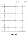
- Fig. 12 is a sheet of media with a preprinted coordinate system.
-
- The present description will be directed in particular to elements forming part of, or in cooperation more directly with, the method and apparatus in accordance with the present invention. It being understood that elements not specifically shown or described may take various forms well known to those skilled in the art.
- Referring to Fig. 1, there is illustrated a
hardcopy print 10 made in accordance with the present invention. Theprint 10 includes adigital image 12 placed thereon by a variety of known printing techniques. For example, but not by way of limitation, an image may be produced by optically or digitally printing theimage 12 on a photosensitive media, for example, photographic paper, photographic film, or maybe printed on any other hardcopy media by any other known printing devices such as inkjet, thermal, LED, CRT, laser, etc. In the embodiment illustrated,print 10 is a photographic print having acolor image 12 formed thereon by either a digital or optical printer. In addition to the image provided thereon, additional encoded information may be provided thereon, which is undetectable by the viewer. In the particular embodiment illustrated, this is accomplished by providing a printer, which can print directly on the hardcopy print information not normally visible by a viewer under normal viewing conditions. In the particular embodiment illustrated, this is obtained by using an infrared ink which is printed on thehardcopy print 10 after the image has been fully formed thereon. An example of a suitable ink may be obtained from the Eastman Kodak Company, under the tradename N.I.R.F. (near-infrared fluorophore). The information/indicia is printed on theprint 10 so as to enable scanning thereon, which contains information that relates it to the image. In order to accomplish such, it is necessary to provide a coordinate system and information to be read. - Referring to Fig. 2, there is illustrated the
print 10 of Fig. 1 illustrating information which is not normally visible insection 18 which can be read by a scanner. The information in section 18 (shown by dash lines) typically contains information which relates to the image onprint 10. Preferably, as illustrated,print 10 includes acoordinate system 16 which provides a reference whereby certain features/items in theimage 12 can be located and identified. Thecoordinate system 16 is also not normally visible by the viewer under normal viewing conditions, but can be scanned by a scanner. Preferably, as illustrated, theinformation 18 andcoordinate system 16 are provided on the same side and directly over theimage 12. - In the particular embodiment illustrated,
image 12 illustrates twoindividuals house 24 andmountains image 12. For example,informational section 18 may include the names of theindividuals system 16 allows easy identification of the individuals or other items within theimage 12. When theimage 12 is scanned by a digital scanner, both the information relating to theimage 12 and the information withinsection 18 is obtained in a single scanning operation. In the preferred embodiment, information withinsection 18 may further include acode 32 for identifying the particular type information contained therein, including information stating that the hardcopy print does include encoded information. In addition, the names of theindividuals mountains house 24 can be provided. The coordinatesystem 16 allows the locating and identification of these items, which then can be later visually displayed, for example, on a CRT, or used to produce a second hardcopy print wherein the information is actually placed thereon without affecting or detracting from the visual appearance of theimage 12. - Referring to Fig. 3, there is illustrated in schematic form a printer 40 capable of printing onto a
hardcopy print 10 using an ink, which is not normally visible by a viewer under normal viewing conditions. In the particular embodiment illustrated, printer 40 is an inkjet printer having a printhead 42 designed to apply any desired image appropriate on themedia 43 as it passes therethrough. The printhead 42 prints directly overimage 12 onprint 10, however, since an invisible ink is being applied, theimage 12 will be viewed as it would normally be viewed. The printer 40 includes an inlet/supply tray 44 for receivingmedia 43, such ashardcopy print 10, an outlet tray for retaining media that has been passed through the printer, and a printing path along which the photosensitive media passes from supply tray tooutlet tray 46. The printhead 42 is positioned with respect to the printing path so as to provide printing ontomedia 43 as it passes thereby. An appropriate transport mechanism, not shown, is provided for transporting of the media from thesupply tray 44 along the printing path 14 tooutlet tray 46. In the embodiment illustrated, thehardcopy print 10 already has an image formed thereon in which case the informational data and coordinatesystem 16 is placed thereon by the printer 40. Thus, the informational data and coordinate system are separate from the image and printed at a different time. This information can be inputted in a variety of different manners. For example, the image could have been previously scanned and the information provided to a computer, such as a PC, and an appropriate software program could have been provided for illustrating a grid system and allowing of entry of information with respect to the grid system. For example, a mouse or other similar type control unit could have been used to identify certain areas of the image scanned and appropriate data/information can be entered with respect to such location for identifying persons, places, or things, and this information can be stored to a record file, which can be then forwarded over to a printer 40 for printing. The information regarding the image can be entered and/or forwarded to the printer 40 by a variety of known techniques, including hardwire connection or by the internet. Optionally, as illustrated in Fig. 3, the printer may be provided with ascanner 50, which scans the image prior to reaching the printhead 42 where the printhead provides the image. In particular, the image onhardcopy print 10 is scanned by thescanner 50 and displayed ondisplay device 52, for example, a CRT or liquid crystal display. The printer 40 is controlled by anappropriate computer 54 whereby a super-imposed grid system can be provided over the image scanned and data entry can be entered throughkeyboard 56, or any other input device. The information is appropriately encoded and printed onto theimage 12 through the use of printhead 42. Thus, thehardcopy print 10 leaving the printer 40 atoutlet tray 46 will have thereon appropriate encoded information and an orientation system for properly identifying and using said information. The information insection 18 may also contain a code which can be read by a scanner which will identify that thehardcopy print 10 is of the type containing such information and the appropriate information necessary for interpreting the information, including the type of reference orientation provided thereon. Thus, thehardcopy print 10 will allow normal viewing of the image, yet when scanned by an appropriate scanner, will be able to read so as to obtain information not normally visible, which can then later be used for displaying, storing, or producing a hardcopy print which includes such information. - With respect to the ink used by printhead 42, the ink is such that it cannot be normally viewed by individuals, but is still capable of being read by a digital scanner. The
scanner 30 may of any type digital scanner, for example, but not by way of limitation, AVISION 630CS, HP Scanjet 5100C, UMAX Powerlook 200, and Epson ES-1200C. Modification of these scanners is necessary to make the scanner to sense the infrared ink not normally visible. For example, the infrared blocking filter used to prevent infrared light from being sensed by the imager may be selectively removed when it is desired to scan the infrared record. Alternatively, a separate channel for sensing infrared light may be added to the imaging head. Additionally, an infrared light source may need to be added to the scanner. However, it is to be understood that any appropriate other digital scanner may be employed. - Referring to Fig. 4, there is illustrated a modified
printing apparatus 70 made in accordance with the present invention. Thisapparatus 70 is similar to printing apparatus 40, like numerals indicating like parts and like operation. Aprinthead 72 is provided for printing of a digital image obtained from a digital image file/record onto the media passing thereby along printing path 48. In the particular embodiment illustrated, theprinthead 72 comprises an inkjet printhead, however, it is to be understood that any other desired digital printing system may be employed in place ofprinthead 72. Theapparatus 70 includes a second printing system 74, which in the particular embodiment illustrated comprises adigital inkjet printhead 75 similar in operation and construction toprinthead 72. Theprinthead 75 produces a orientation grid and data information as previously discussed with respect to printhead 42. A sufficient amount of spacing is provided between theprintheads 72,74 such that the ink being applied by one will not substantially affect the ink being applied by the other. - While in the particular embodiment illustrated in Fig. 4 the
image 10 is first produced on themedia 43, followed by the placement of the information and grid, the present invention is not so limited. In particular, the location of theprintheads printhead 72 is provided after the application of the information and/or orientation system provided byprinthead 75. The ink being applied is of such a nature that it can still be observed by a scanner through the image applied byprinthead 72. An example of a suitable ink used for printing of the customer image is sold by Eastman Kodak Company under the tradename KODAK PROFESSIONAL DYE INKS and an appropriate suitable ink for placement of the information and grid byprinthead 72 is sold by Eastman Chemical Company under the tradename N.I.R.F. (near-infrared fluorophore) inks. - Referring to Fig. 5, there is illustrated a scanner and output system, which may be used to scan a
hardcopy print 10 of the type having encoded invisible information as previously discussed. In particular, the system includes adigital scanner 30, which may be of any digital type as commonly available, for example, but not by way of limitation, a Vision 630CS, HP Scanjet 5100C, Newmax Power Look 200 and Epson ES 1200C. Theimage 12 on thehardcopy print 10 is scanned byscanner 30, thereby the appropriate information regarding the image is obtained as is typically done with prior art scanners. Thescanner 30, in the embodiment illustrated, has been programmed to recognize and read informational data such as provided bysection 18 and coordinatesystem 16. The coordinatesystem 16 is used primarily so that information contained insection 18 can be related to items/objects in theimage 12. Anappropriate computer 49 is provided for interpreting of the data obtained by scanner and is sent forward to anappropriate output device 47. Theoutput device 47 may comprise a variety of different digital output devices, for example, but not by way of limitation, various digital type printers, display devices, or storage memory devices whereby the information can then later be retrieved directly or through the internet, or other communication system. - Referring to Fig. 6, there is illustrated an
image 12 on adisplay screen 53 obtained from scanninghardcopy print 10 onscanner 30 wherein information provided ininformation section 18 is displayed with respect to the objects or persons provided in theimage 12. In the particular embodiment illustrated, it can be seen that the two individuals are identified as Grandma X and Aunt Y, and that the locations provided with respect to the cabin are illustrated therein. As previously noted, theoutput device 47 may include a printer, in which case the image with the annotated information may be printed if so desired. - It is to be understood that various modifications may be made without departing from the scope of the present invention. In particular, in Fig. 2 there is illustrated an coordinate
system 16 in the form of an unique, symmetrical shape. However, the present invention is not limited to this particular type orientation system. Various other orientation system/patterns may be used as desired. The principal function of the coordinatesystem 16 is for providing a reference by which the information contained insection 18 may be associated with the particular items within theimage 12. Referring to Fig. 7, there is illustrated a modifiedhardcopy print 10 made in accordance with the present invention. In this embodiment, there is provided anorientation system 116 in the form of a grid pattern. The information section would provide an appropriate code identifying the particular relationship with respect to the grid pattern so that particular items may be identified. It is, of course, understood that various other orientation schemes may be used as long as they are able to allow identification of particular locations within the image for locating encoded information in specific areas of theimage 12. - In the embodiments illustrated in Fig. 2, the
hardcopy print 10 includes information in machine-readable format. However, the present invention is not so limited. For example, referring to Fig. 8 there is illustrated ahardcopy print 210 made in accordance with the present invention, like numerals indicating like parts. However, in this embodiment, agrid 119 is provided along with informational information in a corner identifying certain objects with respect to the grid. This is particularly useful when the invisible ink being used can be viewed under special viewing conditions. For example, under normal viewing conditions the ink is such that it is not visible to the viewer, however, under ultraviolet light, typically referred to as a black light, the information printed thereon would be visible. In the particular embodiment illustrated, the information is provided in association with agrid 119, however, since the information can be viewed, thegrid 119 may be dispensed with, and the information may be put directly in association therewith. In such situations, thegrid 119 may be maintained so that any machine-readable information can still be scanned and associated with the image for later printing and storing of theimage 12. - Referring to Fig. 9, there is illustrated a modified form of the present invention illustrating a different way in which the information may be displayed. In this particular embodiment, the image scanned is illustrated on a display screen. The informational data is placed off to the one side of the image so that the image may be viewed unobstructed, yet also while in viewing the image in the unobstructed view. A
grid 119 may be optionally placed over theimage 12 in the situations where additional information is provided for specific identification of items within the image. - Fig. 10 is a view similar to Fig. 9 illustrating the image without the grid system.
- Referring to Fig. 11, there is illustrated a modified
hardcopy print 310 made in accordance with the present invention. Thehardcopy print 310 is similar tohardcopy 10, like numerals indicating like parts. However, in this particular instance, the informational data is printed in the actual location being related to. Thus, in this situation, there is no need to provide a coordinate system. - Referring to Fig. 12, there is illustrated a sheet of
media 400 with a preprinted coordinatesystem 410 in the form of a grid which is not visible to the human eye under normal viewing conditions. In the particular embodiment illustrated, the coordinatesystem 410 is preprinted on themedia 400 using an infrared ink. The coordinatesystem 410 can have a specific pattern corresponds to a different type media. For example, a grid with lines spaced at 1/8 inch (3.175 mm) intervals can designate thermal media such as KODAK PROFESSIONAL EKTATHERM XLS Print Paper used with a KODAK 8650 PS Color Printer. A grid with lines spaced at 1/4 inch (6.35 mm) intervals can designate inkjet media such as KODAK Inkjet Photo Stickers which can be printed on a Hewlett Packard DeskJet 870Cxi. Similarly, the coordinatesystem 410 can have a specific pattern which corresponds to a specific image type to be placed thereon. For example, a grid with dashed lines can designate an image originated from a digital file, while a grid with solid lines can designate an image originating from an optically captured image. Likewise, a specific pattern may indicate a professionally generated image. Care must be taken to insure the media type corresponding to the type of image being printed is used. If the media is scanned prior to printing, the printing application can indicate which media is appropriate and refuse to print for improper matches of file type and media. Additionally, in the case of professional images, the grid pattern may indicate ownership of the imagery, and can be used to prevent enabled stations from copying the image and also be used as a means for identifying the material is copyrighted. - An image is printed on a
media 400 having a pre-printed coordinatesystem 410 such as the grid not being visible to the human eye under normal viewing conditions, by first scanning the media using a scanner 30 (See Fig. 5), or the printer 40 (See Fig. 3) to determine the type and location of the pre-printed coordinatesystem 410 provided. Then providing an image 12 (See Fig. 1) to be printed which hasinformation 18, such as illustrated in Fig. 8, relating to a particular location on the image which can be defined by the coordinate system and printing the image on the media in accordance with the data with respect to the coordinate system. - Alternatively, the user may indicate to the printing device which type of media is being used and which type coordinate system is to be applied thereto. Thus, the media need not be scanned for the invisible printed matter. Various other changes and modifications may be employed. For example, any desired media may be used and any desired digital printing technology may be employed, such as electrophotography or thermal printing. Additionally, when thermal printing is used, the clear top layer of the thermal media may contain the coordinate system.
Claims (9)
- A method for making a digital print, comprising the steps of:a) obtaining a digital image file containing an image for printing by a digital printer;b) printing onto a media using a digital printer on said image; andc) printing a coordinate system that is not being visible to the human eye under normal viewing conditions separate from said printing of said image, said coordinate system being capable of locating a specific area of said image on said print.
- A method for making a digital print, comprising the steps of:a) obtaining a print containing an image; andb) printing a coordinate system on said print over said image, said coordinate system is not visible to the human eye under normal viewing conditions and is separate said image, said coordinate system being capable of locating a specific area of said image on said print.
- A digital printer comprising:a first printing mechanism for digitally printing a visible image on a media; anda second printing mechanism for digitally printing a coordinate system that is not visible to the human eye under normal viewing conditions on said media.
- A method for printing an image on a media having a pre-printed coordinate system thereon, said pre-printed coordinate system is not visible to the human eye under normal viewing conditions, said method comprising the steps of:a) scanning said media so as to determine if said pre-printed coordinate system is provided thereon;b) providing an image to be printed on said media which has information specific to a particular location on said image which can be defined by said coordinate system; andc) printing an image on said media in accordance with said data for printing said image with respect to said coordinate system.
- A computer program product, comprising a computer readable storage medium having a computer program stored therein which when loaded in a computer will enable a digital printer to perform the step of:a) printing an image and a predetermined coordinate system on a medium, said coordinate system not being visible to the human eye under normal viewing conditions, said image having associated data relating to a particular aspect with respect to a location defined by said coordinate system.
- A computer program product, comprising a computer readable storage medium having a computer program stored therein which when loaded in a computer will enable a digital printer to perform the steps of:a) relating a digital image with respect to a predetermined coordinate system; andb) printing said digital image and on a media having said coordinate system, said coordinate system not being visible to the human eye under normal viewing conditions.
- The invention according to claims 1, 2, 3, or 4 further comprising the step of providing information with respect to said specific area.
- The invention according to claims 1, 2, 3, or 4 wherein said information and/or coordinate system is printed directly over said image.
- A method according to claim 6 further comprising the step of modifying the image prior to printing.
Applications Claiming Priority (2)
| Application Number | Priority Date | Filing Date | Title |
|---|---|---|---|
| US339605 | 1989-04-17 | ||
| US09/339,605 US6894794B1 (en) | 1999-06-24 | 1999-06-24 | Method and apparatus for making a print having an invisible coordinate system |
Publications (2)
| Publication Number | Publication Date |
|---|---|
| EP1065875A2 true EP1065875A2 (en) | 2001-01-03 |
| EP1065875A3 EP1065875A3 (en) | 2002-12-04 |
Family
ID=23329803
Family Applications (1)
| Application Number | Title | Priority Date | Filing Date |
|---|---|---|---|
| EP00202062A Withdrawn EP1065875A3 (en) | 1999-06-24 | 2000-06-13 | Method and apparatus for making a print having an invisible coordinate system |
Country Status (4)
| Country | Link |
|---|---|
| US (1) | US6894794B1 (en) |
| EP (1) | EP1065875A3 (en) |
| JP (1) | JP2001038983A (en) |
| AU (1) | AU4264000A (en) |
Cited By (1)
| Publication number | Priority date | Publication date | Assignee | Title |
|---|---|---|---|---|
| AT508824B1 (en) * | 2009-09-29 | 2013-06-15 | Durst Phototech Digital Tech | METHOD FOR THE UNIQUE IDENTIFICATION OF A PRINTED PART |
Families Citing this family (22)
| Publication number | Priority date | Publication date | Assignee | Title |
|---|---|---|---|---|
| US6786420B1 (en) | 1997-07-15 | 2004-09-07 | Silverbrook Research Pty. Ltd. | Data distribution mechanism in the form of ink dots on cards |
| US6618117B2 (en) | 1997-07-12 | 2003-09-09 | Silverbrook Research Pty Ltd | Image sensing apparatus including a microcontroller |
| US6624848B1 (en) | 1997-07-15 | 2003-09-23 | Silverbrook Research Pty Ltd | Cascading image modification using multiple digital cameras incorporating image processing |
| US6690419B1 (en) | 1997-07-15 | 2004-02-10 | Silverbrook Research Pty Ltd | Utilising eye detection methods for image processing in a digital image camera |
| US6879341B1 (en) | 1997-07-15 | 2005-04-12 | Silverbrook Research Pty Ltd | Digital camera system containing a VLIW vector processor |
| US7551201B2 (en) | 1997-07-15 | 2009-06-23 | Silverbrook Research Pty Ltd | Image capture and processing device for a print on demand digital camera system |
| US7110024B1 (en) | 1997-07-15 | 2006-09-19 | Silverbrook Research Pty Ltd | Digital camera system having motion deblurring means |
| AUPP702098A0 (en) | 1998-11-09 | 1998-12-03 | Silverbrook Research Pty Ltd | Image creation method and apparatus (ART73) |
| AUPQ056099A0 (en) | 1999-05-25 | 1999-06-17 | Silverbrook Research Pty Ltd | A method and apparatus (pprint01) |
| US6813039B1 (en) * | 1999-05-25 | 2004-11-02 | Silverbrook Research Pty Ltd | Method and system for accessing the internet |
| US7535582B1 (en) * | 2000-10-20 | 2009-05-19 | Silverbrook Research Pty Ltd | Digital photographic duplication system with image quality restoration |
| US8103877B2 (en) * | 2000-12-21 | 2012-01-24 | Digimarc Corporation | Content identification and electronic tickets, coupons and credits |
| US7042470B2 (en) | 2001-03-05 | 2006-05-09 | Digimarc Corporation | Using embedded steganographic identifiers in segmented areas of geographic images and characteristics corresponding to imagery data derived from aerial platforms |
| US7061510B2 (en) * | 2001-03-05 | 2006-06-13 | Digimarc Corporation | Geo-referencing of aerial imagery using embedded image identifiers and cross-referenced data sets |
| US7197160B2 (en) * | 2001-03-05 | 2007-03-27 | Digimarc Corporation | Geographic information systems using digital watermarks |
| US7249257B2 (en) | 2001-03-05 | 2007-07-24 | Digimarc Corporation | Digitally watermarked maps and signs and related navigational tools |
| US20030193684A1 (en) * | 2002-04-10 | 2003-10-16 | Kendall David R. | Method and system for diagnosing printing defects |
| WO2005076985A2 (en) * | 2004-02-04 | 2005-08-25 | Digimarc Corporation | Digital watermarking image signals on-chip and photographic travel logs through digital watermarking |
| US7515285B2 (en) * | 2005-09-26 | 2009-04-07 | Kabushiki Kaisha Toshiba | Method and apparatus for image processing |
| US7945070B2 (en) * | 2006-02-24 | 2011-05-17 | Digimarc Corporation | Geographic-based watermarking keys |
| US9950389B1 (en) * | 2014-09-19 | 2018-04-24 | EMC IP Holding Company LLC | Laser calibration |
| US11416184B2 (en) | 2018-12-21 | 2022-08-16 | Hewlett-Packard Development Company, L.P. | Printing target objects based on rendering data |
Citations (4)
| Publication number | Priority date | Publication date | Assignee | Title |
|---|---|---|---|---|
| US5661506A (en) * | 1994-11-10 | 1997-08-26 | Sia Technology Corporation | Pen and paper information recording system using an imaging pen |
| US5852434A (en) * | 1992-04-03 | 1998-12-22 | Sekendur; Oral F. | Absolute optical position determination |
| WO1999019823A2 (en) * | 1997-10-10 | 1999-04-22 | Interval Research Corporation | Methods and systems for providing human/computer interfaces |
| WO1999050736A1 (en) * | 1998-04-01 | 1999-10-07 | Xerox Corporation | Paper indexing of recordings |
Family Cites Families (19)
| Publication number | Priority date | Publication date | Assignee | Title |
|---|---|---|---|---|
| US5360235A (en) | 1969-11-01 | 1994-11-01 | The United States Of America As Represented By The Secretary Of The Navy | Secret optical marking |
| US4503468A (en) | 1981-10-09 | 1985-03-05 | Northern Telecom Limited | Interactive viewgraph system |
| JPS58119076A (en) | 1982-01-08 | 1983-07-15 | Toshiba Corp | Picture editing device |
| US4965678A (en) | 1987-03-03 | 1990-10-23 | Canon Kabushiki Kaisha | Area designation apparatus in image processing system |
| JPH07101915B2 (en) | 1987-09-21 | 1995-11-01 | コニカ株式会社 | Image processing device |
| US5335095A (en) | 1987-12-16 | 1994-08-02 | Minolta Camera Kabushiki Kaisha | Image forming apparatus capable of editing color image |
| US5410642A (en) * | 1989-08-23 | 1995-04-25 | Dai Nippon Printing Co., Ltd. | ID card issuing system |
| US5075787A (en) | 1989-09-14 | 1991-12-24 | Eastman Kodak Company | Reproduction apparatus and method with alphanumeric character-coded highlighting for selective editing |
| US5406389A (en) | 1991-08-22 | 1995-04-11 | Riso Kagaku Corporation | Method and device for image makeup |
| JPH05127367A (en) * | 1991-10-30 | 1993-05-25 | K D K Kk | Halftone film for printing |
| JP3080335B2 (en) * | 1992-03-26 | 2000-08-28 | 大日本印刷株式会社 | Register mark detection method on transparent web |
| JP3120554B2 (en) * | 1992-03-30 | 2000-12-25 | 大日本印刷株式会社 | Registration method and apparatus for printing |
| JPH06284270A (en) | 1993-03-29 | 1994-10-07 | Toshiba Corp | Image forming device |
| KR0153394B1 (en) | 1993-09-14 | 1998-11-16 | 미따라이 하지메 | Image processing apparatus capable of performing marker editing |
| US5862270A (en) * | 1995-12-08 | 1999-01-19 | Matsushita Electric Industrial Co., Ltd. | Clock free two-dimensional barcode and method for printing and reading the same |
| US5675400A (en) | 1995-12-20 | 1997-10-07 | Eastman Kodak Company | Method of reproducing a portion of a photograph |
| US5980016A (en) * | 1996-04-22 | 1999-11-09 | Hewlett-Packard Company | Systems and method for determining presence of inks that are invisible to sensing devices |
| US5745248A (en) | 1997-02-03 | 1998-04-28 | Xerox Corporation | Transparent edit sheet with attached background |
| US6499822B1 (en) * | 1998-04-27 | 2002-12-31 | Canon Kabushiki Kaisha | Method and apparatus for forming an image on a recording medium with contraction and expansion properties |
-
1999
- 1999-06-24 US US09/339,605 patent/US6894794B1/en not_active Expired - Fee Related
-
2000
- 2000-06-13 EP EP00202062A patent/EP1065875A3/en not_active Withdrawn
- 2000-06-23 AU AU42640/00A patent/AU4264000A/en not_active Abandoned
- 2000-06-26 JP JP2000196297A patent/JP2001038983A/en active Pending
Patent Citations (4)
| Publication number | Priority date | Publication date | Assignee | Title |
|---|---|---|---|---|
| US5852434A (en) * | 1992-04-03 | 1998-12-22 | Sekendur; Oral F. | Absolute optical position determination |
| US5661506A (en) * | 1994-11-10 | 1997-08-26 | Sia Technology Corporation | Pen and paper information recording system using an imaging pen |
| WO1999019823A2 (en) * | 1997-10-10 | 1999-04-22 | Interval Research Corporation | Methods and systems for providing human/computer interfaces |
| WO1999050736A1 (en) * | 1998-04-01 | 1999-10-07 | Xerox Corporation | Paper indexing of recordings |
Cited By (1)
| Publication number | Priority date | Publication date | Assignee | Title |
|---|---|---|---|---|
| AT508824B1 (en) * | 2009-09-29 | 2013-06-15 | Durst Phototech Digital Tech | METHOD FOR THE UNIQUE IDENTIFICATION OF A PRINTED PART |
Also Published As
| Publication number | Publication date |
|---|---|
| AU4264000A (en) | 2001-01-11 |
| JP2001038983A (en) | 2001-02-13 |
| EP1065875A3 (en) | 2002-12-04 |
| US6894794B1 (en) | 2005-05-17 |
Similar Documents
| Publication | Publication Date | Title |
|---|---|---|
| US6894794B1 (en) | Method and apparatus for making a print having an invisible coordinate system | |
| US6972859B1 (en) | Authorizing the printing of digital images | |
| US6873435B1 (en) | Print having encoded metadata coupled thereto | |
| US6542622B1 (en) | Methods and articles for determining invisible ink print quality | |
| EP1152592A1 (en) | A method for printing and verifying authentication documents | |
| US6529288B1 (en) | Digital printing system | |
| US5822660A (en) | Copyright protection in color thermal prints | |
| US6806974B1 (en) | Print order receiving apparatus | |
| CA2151755C (en) | Index printing apparatus including exposure control | |
| JPH1023244A (en) | Method for changing visibility of characteristic and information added to hard copy of recorded image | |
| US6795209B1 (en) | Method and apparatus for modifying a hard copy image digitally in accordance with instructions provided by consumer | |
| JPH06250346A (en) | Photographic processing method | |
| US5764870A (en) | Method of making an index print | |
| JP3753279B2 (en) | Method and system for creating print with message | |
| EP0773665A1 (en) | System for producing an index print from photographic negative strips | |
| JP5481364B2 (en) | Image input / output system and reading overwrite unit | |
| JP3903110B2 (en) | Method and system for creating print with message | |
| EP1077435A1 (en) | System for customizing and ordering personalized postage stamps | |
| JP3903109B2 (en) | Print production system with message | |
| JPH09179211A (en) | Digital photographic printing system | |
| JP3228045B2 (en) | Photo processing equipment | |
| JPH07261286A (en) | Index printer | |
| JP2002090867A (en) | Photographic device, photographing method, id card preparation system and id card preparing method | |
| US20070195377A1 (en) | Printing device and printing method | |
| JP2000356832A (en) | Print making device, print making system, photographic film image reader and photographic film image reading system |
Legal Events
| Date | Code | Title | Description |
|---|---|---|---|
| PUAI | Public reference made under article 153(3) epc to a published international application that has entered the european phase |
Free format text: ORIGINAL CODE: 0009012 |
|
| AK | Designated contracting states |
Kind code of ref document: A2 Designated state(s): AT BE CH CY DE DK ES FI FR GB GR IE IT LI LU MC NL PT SE |
|
| AX | Request for extension of the european patent |
Free format text: AL;LT;LV;MK;RO;SI |
|
| PUAL | Search report despatched |
Free format text: ORIGINAL CODE: 0009013 |
|
| AK | Designated contracting states |
Kind code of ref document: A3 Designated state(s): AT BE CH CY DE DK ES FI FR GB GR IE IT LI LU MC NL PT SE |
|
| AX | Request for extension of the european patent |
Free format text: AL;LT;LV;MK;RO;SI |
|
| 17P | Request for examination filed |
Effective date: 20030512 |
|
| AKX | Designation fees paid |
Designated state(s): CH DE FR GB IT LI |
|
| 17Q | First examination report despatched |
Effective date: 20031125 |
|
| STAA | Information on the status of an ep patent application or granted ep patent |
Free format text: STATUS: THE APPLICATION IS DEEMED TO BE WITHDRAWN |
|
| 18D | Application deemed to be withdrawn |
Effective date: 20060210 |