EP1065994B1 - Dilatation and stent delivery system for bifurcation lesions - Google Patents
Dilatation and stent delivery system for bifurcation lesions Download PDFInfo
- Publication number
- EP1065994B1 EP1065994B1 EP99908407A EP99908407A EP1065994B1 EP 1065994 B1 EP1065994 B1 EP 1065994B1 EP 99908407 A EP99908407 A EP 99908407A EP 99908407 A EP99908407 A EP 99908407A EP 1065994 B1 EP1065994 B1 EP 1065994B1
- Authority
- EP
- European Patent Office
- Prior art keywords
- balloon
- guidewire
- lumen
- stent
- bifurcation
- Prior art date
- Legal status (The legal status is an assumption and is not a legal conclusion. Google has not performed a legal analysis and makes no representation as to the accuracy of the status listed.)
- Expired - Lifetime
Links
- 0 CC(CC1)C(*)C1=C(CC=CC)C(C)=C Chemical compound CC(CC1)C(*)C1=C(CC=CC)C(C)=C 0.000 description 1
Images


Classifications
-
- A—HUMAN NECESSITIES
- A61—MEDICAL OR VETERINARY SCIENCE; HYGIENE
- A61F—FILTERS IMPLANTABLE INTO BLOOD VESSELS; PROSTHESES; DEVICES PROVIDING PATENCY TO, OR PREVENTING COLLAPSING OF, TUBULAR STRUCTURES OF THE BODY, e.g. STENTS; ORTHOPAEDIC, NURSING OR CONTRACEPTIVE DEVICES; FOMENTATION; TREATMENT OR PROTECTION OF EYES OR EARS; BANDAGES, DRESSINGS OR ABSORBENT PADS; FIRST-AID KITS
- A61F2/00—Filters implantable into blood vessels; Prostheses, i.e. artificial substitutes or replacements for parts of the body; Appliances for connecting them with the body; Devices providing patency to, or preventing collapsing of, tubular structures of the body, e.g. stents
- A61F2/82—Devices providing patency to, or preventing collapsing of, tubular structures of the body, e.g. stents
- A61F2/856—Single tubular stent with a side portal passage
-
- A—HUMAN NECESSITIES
- A61—MEDICAL OR VETERINARY SCIENCE; HYGIENE
- A61F—FILTERS IMPLANTABLE INTO BLOOD VESSELS; PROSTHESES; DEVICES PROVIDING PATENCY TO, OR PREVENTING COLLAPSING OF, TUBULAR STRUCTURES OF THE BODY, e.g. STENTS; ORTHOPAEDIC, NURSING OR CONTRACEPTIVE DEVICES; FOMENTATION; TREATMENT OR PROTECTION OF EYES OR EARS; BANDAGES, DRESSINGS OR ABSORBENT PADS; FIRST-AID KITS
- A61F2/00—Filters implantable into blood vessels; Prostheses, i.e. artificial substitutes or replacements for parts of the body; Appliances for connecting them with the body; Devices providing patency to, or preventing collapsing of, tubular structures of the body, e.g. stents
- A61F2/95—Instruments specially adapted for placement or removal of stents or stent-grafts
- A61F2/954—Instruments specially adapted for placement or removal of stents or stent-grafts for placing stents or stent-grafts in a bifurcation
-
- A—HUMAN NECESSITIES
- A61—MEDICAL OR VETERINARY SCIENCE; HYGIENE
- A61F—FILTERS IMPLANTABLE INTO BLOOD VESSELS; PROSTHESES; DEVICES PROVIDING PATENCY TO, OR PREVENTING COLLAPSING OF, TUBULAR STRUCTURES OF THE BODY, e.g. STENTS; ORTHOPAEDIC, NURSING OR CONTRACEPTIVE DEVICES; FOMENTATION; TREATMENT OR PROTECTION OF EYES OR EARS; BANDAGES, DRESSINGS OR ABSORBENT PADS; FIRST-AID KITS
- A61F2/00—Filters implantable into blood vessels; Prostheses, i.e. artificial substitutes or replacements for parts of the body; Appliances for connecting them with the body; Devices providing patency to, or preventing collapsing of, tubular structures of the body, e.g. stents
- A61F2/95—Instruments specially adapted for placement or removal of stents or stent-grafts
- A61F2/958—Inflatable balloons for placing stents or stent-grafts
-
- A—HUMAN NECESSITIES
- A61—MEDICAL OR VETERINARY SCIENCE; HYGIENE
- A61F—FILTERS IMPLANTABLE INTO BLOOD VESSELS; PROSTHESES; DEVICES PROVIDING PATENCY TO, OR PREVENTING COLLAPSING OF, TUBULAR STRUCTURES OF THE BODY, e.g. STENTS; ORTHOPAEDIC, NURSING OR CONTRACEPTIVE DEVICES; FOMENTATION; TREATMENT OR PROTECTION OF EYES OR EARS; BANDAGES, DRESSINGS OR ABSORBENT PADS; FIRST-AID KITS
- A61F2/00—Filters implantable into blood vessels; Prostheses, i.e. artificial substitutes or replacements for parts of the body; Appliances for connecting them with the body; Devices providing patency to, or preventing collapsing of, tubular structures of the body, e.g. stents
- A61F2/02—Prostheses implantable into the body
- A61F2/04—Hollow or tubular parts of organs, e.g. bladders, tracheae, bronchi or bile ducts
- A61F2/06—Blood vessels
- A61F2/07—Stent-grafts
-
- A—HUMAN NECESSITIES
- A61—MEDICAL OR VETERINARY SCIENCE; HYGIENE
- A61F—FILTERS IMPLANTABLE INTO BLOOD VESSELS; PROSTHESES; DEVICES PROVIDING PATENCY TO, OR PREVENTING COLLAPSING OF, TUBULAR STRUCTURES OF THE BODY, e.g. STENTS; ORTHOPAEDIC, NURSING OR CONTRACEPTIVE DEVICES; FOMENTATION; TREATMENT OR PROTECTION OF EYES OR EARS; BANDAGES, DRESSINGS OR ABSORBENT PADS; FIRST-AID KITS
- A61F2/00—Filters implantable into blood vessels; Prostheses, i.e. artificial substitutes or replacements for parts of the body; Appliances for connecting them with the body; Devices providing patency to, or preventing collapsing of, tubular structures of the body, e.g. stents
- A61F2/82—Devices providing patency to, or preventing collapsing of, tubular structures of the body, e.g. stents
- A61F2/86—Stents in a form characterised by the wire-like elements; Stents in the form characterised by a net-like or mesh-like structure
- A61F2/90—Stents in a form characterised by the wire-like elements; Stents in the form characterised by a net-like or mesh-like structure characterised by a net-like or mesh-like structure
-
- A—HUMAN NECESSITIES
- A61—MEDICAL OR VETERINARY SCIENCE; HYGIENE
- A61F—FILTERS IMPLANTABLE INTO BLOOD VESSELS; PROSTHESES; DEVICES PROVIDING PATENCY TO, OR PREVENTING COLLAPSING OF, TUBULAR STRUCTURES OF THE BODY, e.g. STENTS; ORTHOPAEDIC, NURSING OR CONTRACEPTIVE DEVICES; FOMENTATION; TREATMENT OR PROTECTION OF EYES OR EARS; BANDAGES, DRESSINGS OR ABSORBENT PADS; FIRST-AID KITS
- A61F2/00—Filters implantable into blood vessels; Prostheses, i.e. artificial substitutes or replacements for parts of the body; Appliances for connecting them with the body; Devices providing patency to, or preventing collapsing of, tubular structures of the body, e.g. stents
- A61F2/02—Prostheses implantable into the body
- A61F2/04—Hollow or tubular parts of organs, e.g. bladders, tracheae, bronchi or bile ducts
- A61F2/06—Blood vessels
- A61F2002/065—Y-shaped blood vessels
-
- A—HUMAN NECESSITIES
- A61—MEDICAL OR VETERINARY SCIENCE; HYGIENE
- A61M—DEVICES FOR INTRODUCING MEDIA INTO, OR ONTO, THE BODY; DEVICES FOR TRANSDUCING BODY MEDIA OR FOR TAKING MEDIA FROM THE BODY; DEVICES FOR PRODUCING OR ENDING SLEEP OR STUPOR
- A61M25/00—Catheters; Hollow probes
- A61M25/10—Balloon catheters
- A61M2025/1043—Balloon catheters with special features or adapted for special applications
- A61M2025/1045—Balloon catheters with special features or adapted for special applications for treating bifurcations, e.g. balloons in y-configuration, separate balloons or special features of the catheter for treating bifurcations
-
- A—HUMAN NECESSITIES
- A61—MEDICAL OR VETERINARY SCIENCE; HYGIENE
- A61M—DEVICES FOR INTRODUCING MEDIA INTO, OR ONTO, THE BODY; DEVICES FOR TRANSDUCING BODY MEDIA OR FOR TAKING MEDIA FROM THE BODY; DEVICES FOR PRODUCING OR ENDING SLEEP OR STUPOR
- A61M25/00—Catheters; Hollow probes
- A61M25/10—Balloon catheters
- A61M2025/1043—Balloon catheters with special features or adapted for special applications
- A61M2025/1056—Balloon catheters with special features or adapted for special applications having guide wire lumens outside the main shaft, i.e. the guide wire lumen is within or on the surface of the balloon
Definitions
- the present invention relates to a system for treating vascular disease. More specifically, the present invention relates to a system for treating a lesion at a bifurcation in the vasculature.
- vascular disease currently represents a prevalent medical condition. Typical vascular disease involves the development of a stenosis in the vasculature. The particular vessel containing the stenosis can be completely blocked (or occluded) or it can simply be narrowed (or restricted). In either case, restriction of the vessel caused by the stenotic lesion results in many well known problems caused by the reduction or cessation of blood circulation through the restricted vessel.
- a bifurcation is an area of the vasculature where a first (or parent) vessel is bifurcated into two or more branch vessels. It is not uncommon for stenotic lesions to form in such bifurcations. The stenotic lesions can affect only one of the vessels (i.e., either of the branch vessels or the parent vessel), two of the vessels, or all three vessels.
- stenosis stenotic lesion
- the first is to deform the stenosis to reduce the restriction within the lumen of the blood vessel. This type of deformation (or dilatation) is typically performed using balloon angioplasty.
- the guidewire is first introduced into one of the branch vessels of the bifurcation.
- the dilatation balloon is then advanced over the guidewire so the distal end of the dilatation balloon is in the branch vessel.
- the balloon is then inflated a number of times, in a known manner, to accomplish dilatation.
- the balloon is then withdrawn proximal of the bifurcation.
- the guidewire is then withdrawn and manipulated into the other branch vessel of the bifurcation.
- the balloon is then advanced over the guidewire, again, and inflated to dilate the second branch vessel.
- both branch vessels can be quite difficult. For example, once the first branch vessel is located under conventional visualization techniques (such as with the use of contrast medium), that vessel is dilated. After withdrawing both the guidewire and the dilatation catheter proximal of the bifurcation, the physician must then attempt to locate the second branch vessel. This can require the introduction of other devices into the vasculature and the region of the bifurcation. This can be somewhat cumbersome.
- Vascular stents are also currently well known, and are deployed as another technique for treating vascular lesions.
- Vascular stents typically involve a tubular stent which is movable from a collapsed, low profile, delivery position to an expanded, deployed position.
- the stent is typically delivered using a stent delivery device, such as a stent delivery catheter.
- the stent is crimped down to its delivery position over an expandable element, such as a stent deployment balloon.
- the stent is then advanced (using the catheter attached to the stent deployment balloon) to the lesion site under any suitable, commonly known visualization technique.
- the balloon is then expanded to drive the stent from its delivery position to its deployed position in which the outer periphery of the stent frictionally engages the inner periphery of the lumen.
- the lumen is predilated using a conventional dilatation catheter, and then the stent is deployed to maintain the vessel in an unoccluded, and unrestricted position.
- the treating physician may then advance a dilatation balloon between the struts of the stent already deployed in order to dilate the second branch vessel.
- the physician must then attempt to maneuver a second stent through the struts of the stent already deployed, into the second branch vessel for deployment.
- This presents significant difficulties For example, dilating between the struts of the stent already deployed tends to distort that stent.
- deploying the second stent through the struts of the first stent is not only difficult, but it can also distort the first stent.
- a system according to the preamble of claim 1 is know from the document WO 97/16217.
- the present invention provides a system for treating a lesion at a bifurcation in a body according to claim 1.
- FIG. 1 illustrates a bifurcation 10 which includes parent vessel 12, first branch vessel 14 and second branch vessel 16.
- FIG. 1 also illustrates that a bifurcation lesion 18 has developed in bifurcation 10.
- Lesion 18 illustrates one common bifurcation lesion in that it extends up into parent vessel 12 and down into both branch vessels 14 and 16.
- FIGS. 2A and 2B illustrate a dilatation and stent deployment device 20.
- Device 20 includes a first sheath 22, and a pair of dilatation balloons 24 and 26. Each dilatation balloon 24 and 26 is coupled to a balloon catheter 28 and 30, respectively, both of which fit within sheath 22. It should also be noted that sheath 22 can be a separate member preferably fixedly disposed about balloon catheters 28 and 30 or can be a dual lumen extrusion which forms part of catheters 20 and 30. Balloons 24 and 26 are similar in construction. Balloon 24 preferably includes proximal end 32 and distal end 34 with an intermediate portion 36 therebetween. The region of balloon 24 between proximal end 32 and intermediate portion 36 preferably forms a smaller diameter (or narrower) balloon segment 38. The region of balloon 24 between intermediate portion 36 and distal end 34 preferably forms a larger diameter balloon segment 40.
- balloon 26 preferably has a proximal end 42, a distal end 44, and an intermediate portion 46 therebetween.
- the region between proximal end 42 and intermediate region 46 preferably forms a smaller diameter (or narrower) balloon segment 48, while the portion of balloon between intermediate region 46 and distal end 44 preferably forms a larger diameter balloon segment 50.
- smaller diameter balloon segments 38 and 48 are preferably formed to reside adjacent one another in parent vessel 12, while larger diameter balloon segments 40 and 50 preferably reside in branch vessels 14 and 16, during dilatation and stent deployment.
- Intermediate section 46 of balloon 26 is simply a necked down diameter reduction area which smoothly transitions the outer diameter of balloon 26 from the larger diameter of balloon segment 50 to the smaller diameter of balloon segment 48.
- intermediate section 36 is a necked down portion which transitions the outer diameter of balloon 24 from the large diameter balloon segment 40 to the smaller diameter balloon segment 38.
- intermediate section 46 preferably (and optionally) includes a preformed bend section 62.
- Preformed bend section 62 is preferably formed such that distal end 44 of balloon 26 extends away from distal end 34 of balloon 24 at any desired angle ⁇ . In one arrangement, ⁇ is in a range of approximately 30° - 70°, while in another arrangement, ⁇ is in a range of approximately 45° - 60°. In any case, upon inflation of balloon 26, preformed bend region 62 causes balloon 26 to deform in the shape shown in FIGS. 2A and 6 such that it can more easily find branch vessel 16, and track guidewire 60 into branch vessel 16.
- FIG. 2B is a cross-sectional end view of balloon 24 taken along section lines 2B-2B in FIG. 2A further illustrating the construction of balloons 24 and 26. Both balloons 24 and 26 are similar with respect to the view shown in FIG. 2B. Therefore, only balloon 24 will be described, for the sake of clarity.
- Balloon 24 preferably includes an outer wall 52 of expandable balloon material.
- Balloon 24 also preferably includes an inner guidewire lumen 54, and an inflation lumen 56.
- guidewire lumen 54 and inflation lumen 56 are coaxially aligned with guidewire lumen 54 disposed within inflation lumen 56.
- Inflation lumen 56 terminates at a proximal region of balloon 24 while guidewire lumen 54 extends through balloon 24 and is bonded to the distal end thereof.
- the length from the distal tip of balloon 24 to the distal end of sheath 22 measures approximately 25 cm.
- Both guidewire lumen 54 and inflation lumen 56 extend from balloon 24 all the way to a proximal end of sheath 22, which preferably resides outside the body during dilatation and stent delivery.
- only inflation lumen 56 extends all the way to the proximal end of sheath 22, while guidewire lumen 54 is of a monorail construction which has a proximal ostium proximal of balloon 24, and has a distal ostium in the region of the distal tip 34 of balloon 24.
- the inflation lumens of both balloons 24 and 26 are combined proximal of the balloons to accommodate simultaneous inflation of balloons 24 and 26.
- both balloons can also have an inflation lumen and a guidewire lumen, so they are suitable for independent inflation, and for tracking of separate guidewires. It should also be noted that, in one arrangement, when balloons 24 and 26 are in the deflated, insertion position, they obtain a low enough profile to both fit within a guide catheter (not shown).
- FIGS. 3-6 illustrate dilatation of bifurcation 10.
- FIG. 3 illustrates that, in a first step, two guidewires 58 and 60 are first introduced into the vasculature (such as through a femoral artery and a guide catheter) and are advanced to bifurcation 10.
- Guidewire 58 is manipulated such that it is advanced down branch vessel 14, while guidewire 60 is manipulated to be advanced down branch vessel 16.
- device 20 is then advanced over guidewires 58 and 60. This is illustrated in greater detail in FIG. 4.
- Device 20 is preferably preloaded, or backloaded, onto guidewires 58 and 60 with balloons 24 and 26 in the deflated position.
- guidewire 58 extends through the guidewire lumen in balloon 24, while guidewire 60 extends through the guidewire lumen in balloon 26.
- Sheath 22 and balloons 24 and 26 are then advanced over guidewires 58 and 60 to bifurcation 10.
- the insertion of device 20 is preferably observed by the treating physician under any suitable visualization technique, such as through the introduction of contrast medium, or fluoroscopy, or the like.
- FIG. 5 illustrates that balloons 24 and 26 are then advanced over guidewires 58 and 60 until the distal tips 34 and 44 of balloons 24 and 26 reside at a desirable location within branch vessels 14 and 16, respectively.
- balloons 58 and 60, and their corresponding catheters 28 and 30, are movable independently of one another. However, in another arrangement, they are fixed relative to one another and sheath 22 and move as a unitary member. Balloons 24 and 26 can be positioned as desired by the treating physician, in order to accomplish optimal dilatation, based upon the size and location of bifurcation 10, and the size of lesion 18.
- balloons 24 and 26 are positioned as shown in FIG. 5, they are inflated to accomplish dilatation of bifurcation 10. This is illustrated in FIG. 6.
- FIG. 6 also illustrates that the two smaller diameter balloon segments 38 and 48 combine to provide dilatation force in parent vessel 12 of bifurcation 10.
- larger diameter balloon segments 40 and 50 extend within branch vessels 14 and 16, respectively, to dilate lesion 18 in those vessels.
- balloons 24 and 26 can be deflated and reinflated any desired number of times, to accomplish optimal dilatation. Once dilatation has been accomplished, balloons 24 and 26 are preferably deflated, and withdrawn proximally over guidewires 58 and 60 and removed from the vasculature.
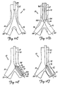
- FIGS. 7A and 7B illustrate a stent which can be deployed by device 20 in bifurcation 10.
- FIG. 7A illustrates that the bifurcation stent preferably includes a first stent portion 64.
- Stent portion 64 can be any suitable, and commercially available stent, such a Palmaz-Schatz stent or an NIR stent.
- Stent 64 preferably includes a tubular structural wall 66. Wall 66 preferably has an aperture 68 formed therein, near a midregion of stent 64, between a first end 70 and a second end 72 thereof.
- the bifurcated stent also preferably includes a second stent portion 74.
- Second stent portion 74 preferably has a first end 76 and a second end 78, wherein the first end 76 is cut at an angle relative to the longitudinal axis of stent 74, First end 76 is preferably coupled to stent 64 about aperture 68, thus forming a bifurcated stent having a first portion 80 which is configured to reside in the parent vessel, and two depending portions 82 and 84 which are configured to be received within branch vessels 14 and 16, respectively.
- the stent is manufactured as one integral stent having a conformation with a main section and two depending leg sections.
- the stent is first preloaded onto device 20 (as shown in FIGS. 8 and 9) such that first portion 80 is disposed over the smaller diameter balloon segments 38 and 48 of balloons 24 and 26, respectively. Also, depending portions 82 and 84 are preferably disposed over the larger diameter balloon segments 40 and 50.
- the bifurcated stent is preferably loaded onto device 20 while the balloons 24 and 26 are in the deflated position and the stent is crimped down over balloons 24 and 26 for delivery.
- balloons 24 and 26, are backloaded onto guidewires 58 and 60.
- Device 20 is then advanced through the vasculature (in the same manner as indicated above with respect to FIGS. 3-5) until balloons 24 and 26, with a bifurcated stent mounted thereon, are disposed in bifurcation 10 in the position shown in FIG. 8.
- Balloons 24 and 26 are then inflated, as shown in FIG. 9.
- device 20 provides significant advantages over prior bifurcation dilatation and stent deployment techniques.
- device 20 is capable of dilating both branch vessels 14 and 16 at the same time.
- device 20 is capable of deploying a stent in both branch vessels at the same time. This significantly reduces the likelihood that either of the branch vessels 14 or 16 will collapse during dilatation and stent deployment.
- both dilatation and stent deployment can be accomplished without removing either of the guidewires 58 or 60, or without repositioning either of the guidewires. Rather, the guidewires simply need to be placed at the appropriate positions within branch vessels 14 and 16, and left throughout both dilatation and stent deployment.
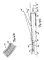
- FIGS. 10A-10C illustrate a bifurcation dilatation device 86 in accordance with the present invention.
- FIG. 10B is a cross-sectional view taken along section lines 10B-10B in FIG. 10A and FIG. C is a view rotated 90° about the longitudinal axis relative to the view shown in FIG. 10A.
- Device 86 includes guidewire sheath 88, catheter 90, and balloon 92.
- Sheath 88 is preferably a separate member from catheter 90 and balloon 92.
- FIG. 10A also shows both guidewires 58 and 60.
- Guidewires 58 and 60 are preferably approximately 0,025 cm (0.010 inches) in diameter, but can have any suitable guidewire dimensions.
- Guidewire sheath 88 is preferably simply a sheath (typically polyethylene) which is disposed about guidewires 58 and 60, and is sized to be advanced over guidewires 58 and 60 through the vasculature, to bifurcation 10, preferably through a guide catheter (not shown).
- Balloon 92 preferably includes a proximal end 100 and a distal end 104 and is eccentrically located on shaft 90. Distal end 104 is preferably disposed just proximal of the distal tip of shaft 90.
- Balloon 92 and the lumens 93 and 94 can be formed by using a triple lumen extrusion process. Alternatively, the lumens can be formed by discrete processing steps, such as inserting a lumen tube through balloon 92 and then bonding or welding the lumen tube to the balloon, or shaft 90, at appropriate locations.
- shaft 90 is an over-the-wire shaft, it is preferably formed of a suitable polymer material.
- shaft 90 can also extend proximally to a stainless steel hypotube shaft (not shown) and be bonded to the stainless steel hypotube shaft at a desirable location. It may also be desirable to have a stainless steel extension, or support shaft 95, extending from the hypotube shaft to a region proximate balloon 92, to provide rigidity to enhance pushability of shaft 90 and balloon 92.
- Shaft 90 also preferably includes an inflation lumen 93 (shown in FIG. 10B), as well as guidewire sheath lumen 94.
- Inflation lumen 93 has an opening 97 which communicates with the interior of balloon 92.
- Lumen 93 extends proximally along shaft 90, all the way to the proximal end of shaft 90 which resides outside the body during dilatation and stent deployment.
- Guidewire sheath lumen 94 can extend all the way to the proximal end of shaft 90, or can have a proximal ostium which is disposed just proximal of the proximal end 100 of balloon 92, and also proximal of the proximal end 98 of slit 96 (described below).
- Shaft 90 includes slit 96 which has a proximal end 98, disposed just proximal of proximal end 100 of balloon 92, and a distal end 102 which is coterminous with the distal tip of balloon 92.
- slit 96 is simply a cut or separation made in the wall of shaft 90.
- the distal end of slit 96 has a v-cut lead in and the proximal end has a relief hole to inhibit tearing.
- single balloon 92 and device 86 can be used to dilate both branch vessels 14 and 16 of bifurcation 10 by alternatively switching from following one guidewire 58, to following the other guidewire 60, without removal of device 86 from the vessel. Briefly, this is done by first advancing balloon 92 along guidewire 58, while allowing guidewire 60 to slip through slit 96 as balloon 92 enters the first branch vessel 14. Then, balloon 92 is withdrawn such that both guidewires 58 and 60 are again within guidewire lumen 94. Balloon 92 is then rotated and advanced along guidewire 60, allowing guidewire 58 to exit guidewire lumen 94 through slit 96. This allows balloon 92 to be advanced along guidewire 60 into the other branch vessel 16 for dilatation of that branch vessel.
- FIG. 11A illustrates a first step in dilating bifurcation 10 with device 86.
- Guidewire 58 is first advanced to bifurcation 10, and the lesion in branch vessel 14 is crossed with guidewire 58. Then, as shown in FIG. 11B, guidewire sheath 88 is advanced over guidewire 58 such that its distal end is disposed just proximal of bifurcation 10.
- Guidewire 60 is then advanced through sleeve 88 and across the lesion in branch vessel 16. This is indicated in FIG. 11C.
- sleeve 88 can be backloaded or preloaded onto wires 58 and 70.
- sleeve 88 is preferably loaded within the distal end of lumen 94 or catheter 90, and both guidewires 58 and 60 are loaded into sleeve 88 in guidewire lumen 94 of shaft 90.
- device 86 is advanced over guidewires 58 and 60, and sleeve 88 (possibly with the assistance of a guide catheter - not shown) until the distal tip 102 of slit 96 is closely proximate, or adjacent, the distal tip of sleeve 88.
- FIG. 11D It can be seen that the distal tip of sleeve 88 is positioned at a point where guidewires 58 and 60 diverge from one another into branch vessels 14 and 16, respectively.
- Device 86 is then rotated such that slit 96 engages wire 58.
- Device 86 is then advanced distally while wires 58 and 60 are held longitudinally in place. This causes guidewire lumen 94 to track guidewire 60, while allowing guidewire 58 to escape from guidewire lumen 94 along slit 96.
- guidewire lumen 94 to track guidewire 60, while allowing guidewire 58 to escape from guidewire lumen 94 along slit 96.
- the distal end of device 86 follows guidewire 60 into branch vessel 16 of bifurcation 10.
- Device 86 is further advanced along guidewire 60 to a position where balloon 92 is sufficiently disposed within branch vessel 16. This is indicated in FIG. 11E.
- balloon 92 is positioned within branch vessel 16, balloon 92 is inflated, as shown in FIG. 11F. This dilates branch vessel 16.
- balloon 92 can be inflated and deflated any desired number of times, as is well known, in order to accomplish desired dilatation of branch vessel 16.
- Balloon 92 is then deflated and device 16 is withdrawn proximally such that the distal tip 102 of slit 96 is again closely proximate the distal tip of sleeve 88 as shown in FIG. 11G.
- FIG. 11G also illustrates that, once tip 102 is withdrawn just proximal of the distal tip of sleeve 88, both guidewires 58 and 60 fully reside within guidewire lumen 94, since sleeve 88 also resides coaxially within guidewire lumen 94.
- device 86 In order to dilate the lesion in branch vessel 14, device 86 is again rotated until slit 96 is in position to engage guidewire 60. Device 86 is then advanced distally, while holding guidewires 58 and 60 longitudinally in place. This causes guidewire lumen 94 to track along guidewire 58, while allowing guidewire 60 to escape through slit 96. Device 86 is advanced further distally until balloon 92 resides sufficiently within branch vessel 14, as illustrated in FIG. 11H.
- Balloon 92 is then inflated, as shown in FIG. 11I, in order to dilate the branch vessel 14.
- balloon 92 can be inflated and deflated a desired number of times in order to accomplish sufficient dilatation.
- Balloon 92 is then deflated, and device 86 is withdrawn from the vasculature.
- device 86 can be withdrawn from the vasculature, along with guidewires 58 and 60, in a single step.
- dilatation of one of branching vessels 14 or 16 can cause the other of branching vessels 14 or 16 to collapse. This is undesirable for a number of reasons. For example, if the vessel is collapsed, or even restricted, blood flow through the vessel is undesirably obstructed. Further, if the vessel collapses, it does not provide support, or back pressure, to the branch vessel being dilated. This can result in inefficient dilatation of that branch vessel.
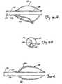
- FIGS. 12A-12C illustrate a perfusion tube 106 in accordance with one aspect of the present invention.
- Perfusion tube 106 in one preferred embodiment, is formed of a generally tubular structure 108 which is made of polyethylene, or another suitable polymer material.
- Tubular structure 108 is attached, such as by welding, adhesive, or another suitable bonding technique, to a push wire 110 which is made of stainless steel, or another suitable material.
- Tubular member 108 also includes a slit, or elongate aperture, 112 which extends from a proximal end 114 thereof to a distal end 116.
- FIG. 12B is an end view of tubular member 108 and illustrates that slit 112 extends all the way through the tubular wall of member 108.
- Tubular member 108 is preferably formed of a material with sufficient rigidity that the tubular member 108 will not roll up on itself about its longitudinal axis. Such rolling may be further inhibited by providing slit 112 at an angle relative to the longitudinal axis of tubular member 108, as shown in FIG. 12A.
- Perfusion tube 106 can be used in much the same way as device 86 described with respect to FIGS. 10A-11I. In other words, perfusion tube 106 can be used to selectively track one of guidewires 58 and 60 into one of branch vessels 14 and 16, and then to track the other of guidewires 58 and 60 into the other branch vessels 14 and 16, without removing perfusion tube 106 from the vasculature.
- FIG. 12C illustrates that, in a preferred embodiment, after sheath 88 is advanced to the position shown in FIG. 11B, perfusion tube 106 is advanced over sheath 88 and rotated such that slit 112 engages guidewire 58. Perfusion tube 106 is then advanced further distally, by pushing on push wire 110, such that the lumen within perfusion tube 106 tracks along guidewire 60 while guidewire 58 is allowed to escape through slit 112. Of course, perfusion tube 106 can be positioned to track guidewire 58 for placement within branch vessel 14.
- perfusion tube 106 is withdrawn back over sleeve 88 such that both guidewires 58 and 60 are again within the lumen of tubular member 108.
- Perfusion tube 106 is then rotated such that slit 112 engages guidewire 60, and perfusion tube 106 is again advanced. This time, the lumen in perfusion tube 106 tracks over guidewire 58 while allowing guidewire 60 to escape such that perfusion tube 106 can be advanced into branch vessel 14.
- perfusion tube 106 can easily be used with device 86. This is illustrated in FIGS. 13A-13C.
- perfusion tube 106 is loaded onto sleeve 88 distally of device 86.
- perfusion tube 106 could also be loaded onto sleeve 88 proximally of device 86.
- perfusion tube 106 is loaded distally will be described in detail.
- perfusion tube 106 is preferably advanced over sleeve 88 until the distal end 116 of perfusion tube 106 is closely proximate the distal end of sleeve 88. This is illustrated in FIG. 3A.
- perfusion tube 106 is rotated such that slit 112 engages wire 58. Perfusion tube 106 is then advanced such that it tracks guidewire 60 into branch vessel 16 while guidewire 58 is allowed to escape through slit 112.
- Device 86 is then advanced distally until its distal end is closely proximate the distal end of sleeve 88. As described with respect to FIGS. 11A-11I, device 86 is rotated to a position where slit 96 engages wire 60. Device 86 is advanced distally such that guidewire lumen 94 tracks guidewire 58, allowing guidewire 60 to escape through slit 96.
- perfusion tube 106 By continuing to advance perfusion tube 106 and device 86 as described above, perfusion tube 106 will reside in branch vessel 16 while balloon 92 of device 86 will reside in branch vessel 14. This is illustrated in FIG. 13B. Balloon 92 can then be inflated to accomplish dilatation of branch vessel 14 without collapsing branch vessel 16.
- both devices can then be withdrawn proximally (while holding guidewires 58 and 60 and sleeve 88 in place) to the position shown in FIG. 13A.
- Perfusion tube 106 is then rotated such that slot 112 engages wire 60 and so that perfusion tube 106 can be advanced within branch vessel 14.
- Device 86 is positioned such that slit 96 engages guidewire 58 so balloon 92 can be advanced within branch vessel 16. This is indicated in FIG. 13C.
- Balloon 92 is then inflated to dilate branch vessel 16. Since perfusion tube 106 now resides in branch vessel 14, dilatation can be accomplished without collapsing branch vessel 14.
- perfusion tube 106 can be used to accomplish dilatation as well.
- tubular member 108 has a lumen therethrough which is sufficiently sized to receive balloon 92 in the deflated position. Both device 96 and perfusion tube 106 are rotated such that slit 96 and slot 112 both engage the same guidewire (such as guidewire 60 illustrated in FIG. 13D). Balloon 92 is placed within the lumen of perfusion tube 106 in the deflated position, and both balloon 92 and perfusion tube 106 are placed in the same branch vessel (such as branch vessel 14). Balloon 92 is then inflated using perfusion tube 106 to exert outward pressure to dilate the chosen branch vessel.
- a second perfusion tube can also be used and inserted in the opposite branch vessel to prevent that branch vessel from collapsing during dilation.
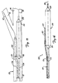
- FIG. 14A illustrates a dilatation and stent deployment device 120.
- Device 120 is illustrated as an over-the-wire catheter but could be implemented in a monorail construction as well.
- Device 120 includes a catheter shaft 122 and balloon 124.
- Balloon 124 includes proximal end 126, distal end 128 and intermediate portion 130.
- Shaft 122 includes inflation lumen 132, first guidewire lumen 134, and second guidewire lumen 136. In one arrangement the inflation lumen 132 and first guidewire lumen 134 are coaxially aligned with guidewire lumen 134 disposed within inflation lumen 132.
- Inflation lumen 132 is preferably in fluid communication with the interior of balloon 124 through aperture 138.
- a proximal end of shaft 122 is thus coupleable to a source of fluid pressure for delivering fluid under pressure to, and withdrawing fluid from, the interior of balloon 124.
- First guidewire lumen 134 is preferably configured as a conventional guidewire lumen which extends from the proximal end of catheter shaft 122 through the distal end of catheter shaft 122 (distal of balloon 124). This allows catheter shaft 122 to be advanced over guidewire 58 or 60 in a conventional manner.
- the second guidewire lumen 136 also extends from the proximal end of catheter shaft 122 to a distal region of catheter shaft 122, but not all the way to the distal tip of shaft 122. Rather, the distal opening of guidewire lumen 136 is disposed in intermediate region 130 of balloon 124. Thus, guidewire 58 or 60 (guidewire 60 illustrated in FIG. 14A) exits the distal ostium of guidewire lumen 136 at the intermediate portion 130 of balloon 124.
- device 120 can be formed in a monorail structure in which the proximal opening of each of guidewire lumens 134 and 136 do not extend all the way to the proximal end of shaft 122. In that arrangement, guidewire lumens 134 and 136 extend proximally only to a point proximal of the proximal end 126 of balloon 124.
- FIG. 14B shows a greatly enlarged portion of second guidewire lumen 136 in region 140 of balloon 124.
- FIG. 14B illustrates that, in one arrangement, a coil 142 is disposed within second guidewire lumen 136, at least in region 140 proximate balloon 124.
- Coil 142 can be any suitable material, such as stainless steel, surlyn, polyester, or another suitable material.
- FIG. 14C illustrates a cross-sectional view of a portion of device 120 taken along section lines 14C-14C in FIG. 14A, and illustrates one preferred method of forming balloon portion 124 of device 120.
- a coextruded tube of balloon material is first provided with a pair of lumens therein. Interior pressure is then exerted on the portion of guidewire lumen 136 which extends through balloon 124. This causes guidewire lumen 136 to expand.
- Coil 142 is then placed within the expanded lumen 136 and that region of the balloon material is heated to shrink the balloon material down over coil 142 and thereby frictionally secure coil 142 within lumen 136.
- a hole 143 is then drilled in the side of the structural wall portion of balloon 124 in order to form the distal ostium of guidewire lumen 136.
- FIG. 14D illustrates operation of device 120.
- Guidewires 58 and 60 are first preferably advanced across lesion 18 and into branch vessels 14 and 16 as illustrated in FIG. 3. Then, device 120 is either backloaded, or preloaded, onto guidewires 58 and 60 such that one of guidewires 58 and 60 is disposed within lumen 134 and the other is disposed within lumen 136.
- guidewire 58 is disposed within lumen 134
- guidewire 60 is disposed within lumen 136.
- Device 120 is then advanced distally to bifurcation 10. As device 120 is advanced distally, the distal end 128 of balloon 124 tracks along guidewire 58, because guidewire lumen 134 extends out the distal end of shaft 122. This causes the distal end 128 of balloon 124 to extend within branch vessel 14. Balloon 124 is then inflated to dilate branch vessel 14. It should also be noted, of course, that balloon 124 can be used to deploy a stent in branch vessel 14 as well, and that it can be advanced into smaller vessels as well.
- FIG. 14D illustrates stent 150 disposed on the distal end of balloon 124.
- a stent such as stent portion 64 could also be disposed on balloon 124 with guidewire 60 extending out through aperture 68 in the wall structure of stent 64.
- stent 156 is preferably crimped down over the distal portion of balloon 124 in a known manner.
- Balloon 124 is then loaded onto the guidewires and advanced to the position shown in FIG. 14D.
- Balloon 124 is then inflated to drive stent 156 to its expanded, deployed position in which it frictionally engages the inner wall of the lumen of branch vessel 14.
- device 120 In order to dilate, or deploy a stent in, branch vessel 16, device 120 is withdrawn proximally and is reoriented such that guidewire 58 is disposed within lumen 136, and guidewire 60 is disposed within lumen 134. Device 120 is then advanced distally until the distal tip 128 of balloon 124 is disposed within branch vessel 16 (or in another distal vessel). Again, balloon 124 is inflated to either dilate branch vessel 16 or to deploy a stent therein.
- FIG. 14D illustrates, the proximal portion of balloon 124 will still reside in parent vessel 12 while the distal portion of balloon 124 is in either of the branch vessels 14 or 16.
- inflation of balloon 124 can be used to cause simultaneous dilation of parent vessel 12.
- FIGS. 15A and 15B illustrate another method of forming lumen 136 in balloon 124. Rather than providing a separate lumen within the balloon wall structure of balloon 124, as illustrated in FIGS. 14A-14D, a second balloon or cavity 160 is formed within balloon 124 which comprises the portion of guidewire lumen 136 within balloon 124.
- Balloon 124 is first provided. Then, a portion of balloon material is placed within balloon 124, and is inflated to form a second balloon, or cavity, 160 within balloon 124. Balloon 160 is then attached, such as through adhesive, welding or another suitable process, to the interior side wall of balloon 124. An aperture 126 is then drilled in the exterior wall of balloon 124 and into cavity 160, to form the distal ostium of guidewire lumen 136. In addition, the proximal end of balloon 160 is secured about the tube forming the proximal portion of guidewire lumen 136.
- FIG. 16 illustrates another arrangement of a dilatation or stent deployment device in which the distal end of guidewire lumen 136 is formed in a different manner.
- sheath 164 is disposed about the proximal, exterior surface of balloon 124.
- Sheath 164 is secured to the exterior surface of balloon 124 throughout the entire exterior periphery of the proximal end of balloon 124 except at a region 166 which is in alignment with guidewire lumen 136. In that region, sheath 164 is not attached to the exterior surface of balloon 124.
- the space between the exterior surface of balloon 124 and the interior surface of sheath 164 in region 166 defines the distal region of guidewire lumen 136.
- a tube, or other suitable material can be inserted between balloon 124 and sheath 164 in the area of lumen 166 in order to provide additional structural integrity to the lumen.
- FIG. 17 illustrates yet another device 170.
- Device 170 is similar to the device illustrated in FIG. 15A. However, rather than forming a second balloon within the interior of balloon 124 in order to provide the distal region of guidewire lumen 136, device 170 illustrated in FIG. 17 includes a second balloon 168 formed on the exterior of balloon 124. Balloon 168 is coupled, by transition shaft 172, to the proximal portion of guidewire lumen 136. Balloon 168 is formed in a conventional manner, and is simply provided to define the distal region of the second guidewire lumen 136 such that it has a distal ostium in the intermediate portion of balloon 124. Balloon 168 could also be made longer such that its distal end resides in the branch vessel.
- FIG. 18 illustrates yet another device 180.
- Device 180 is similar to device 170 shown in FIG. 17, and similar items are similarly numbered. However, rather than providing a second balloon 168 to provide the distal portion of guidewire lumen 136, device 180 simply provides a tube 182 which is connected to guidewire lumen 136 in shaft 122.
- Tube 182 is preferably a polyethylene tube which is a free floating tube in that it is not attached to the exterior surface of balloon 124.
- Tube 182 has its distal tip defining the distal opening of guidewire lumen 136 in the intermediate region of balloon 124. Tube 182 could also be made longer such that its distal opening resides in the branch vessel.
- the present invention provides significant advantages over prior systems for performing dilatation and stent deployment at bifurcations.
- the present invention provides a system for simultaneously tracking two guidewires which can be positioned in the branch vessels of the bifurcation, and maintained in those branch vessels throughout the entire dilation and stent deployment.
- the present invention provides a system with which dilation and stent deployment can be performed in both branch vessels, without collapsing either. This reduces the cumbersome nature of performing dilation and stent deployment at bifurcations, and also enhances the efficiency of dilation and stent deployment performed in those regions.
Abstract
Description
- The present invention relates to a system for treating vascular disease. More specifically, the present invention relates to a system for treating a lesion at a bifurcation in the vasculature.
- Vascular disease currently represents a prevalent medical condition. Typical vascular disease involves the development of a stenosis in the vasculature. The particular vessel containing the stenosis can be completely blocked (or occluded) or it can simply be narrowed (or restricted). In either case, restriction of the vessel caused by the stenotic lesion results in many well known problems caused by the reduction or cessation of blood circulation through the restricted vessel.
- A bifurcation is an area of the vasculature where a first (or parent) vessel is bifurcated into two or more branch vessels. It is not uncommon for stenotic lesions to form in such bifurcations. The stenotic lesions can affect only one of the vessels (i.e., either of the branch vessels or the parent vessel), two of the vessels, or all three vessels.
- A number of different procedures have been developed to treat a stenotic lesion (stenosis) in the vasculature. The first is to deform the stenosis to reduce the restriction within the lumen of the blood vessel. This type of deformation (or dilatation) is typically performed using balloon angioplasty.
- However, when the lesion is formed in a bifurcation, conventional balloon angioplasty can be somewhat cumbersome. In some cases, two separate guidewires are used. However, where one guide wire is used, the guidewire is first introduced into one of the branch vessels of the bifurcation. The dilatation balloon is then advanced over the guidewire so the distal end of the dilatation balloon is in the branch vessel. The balloon is then inflated a number of times, in a known manner, to accomplish dilatation.
- The balloon is then withdrawn proximal of the bifurcation. The guidewire is then withdrawn and manipulated into the other branch vessel of the bifurcation. The balloon is then advanced over the guidewire, again, and inflated to dilate the second branch vessel.
- Not only is this process somewhat cumbersome, other problems result as well. For example, when the angle between the branch vessels in the bifurcation is fairly small, inflation of the dilatation balloon in one branch vessel can cause the ostium of the other branch vessel to collapse. This results in inefficient dilatation by restricting flow to the other branch vessel.
- Further, locating both branch vessels can be quite difficult. For example, once the first branch vessel is located under conventional visualization techniques (such as with the use of contrast medium), that vessel is dilated. After withdrawing both the guidewire and the dilatation catheter proximal of the bifurcation, the physician must then attempt to locate the second branch vessel. This can require the introduction of other devices into the vasculature and the region of the bifurcation. This can be somewhat cumbersome.
- Vascular stents are also currently well known, and are deployed as another technique for treating vascular lesions. Vascular stents typically involve a tubular stent which is movable from a collapsed, low profile, delivery position to an expanded, deployed position. The stent is typically delivered using a stent delivery device, such as a stent delivery catheter. In one common technique, the stent is crimped down to its delivery position over an expandable element, such as a stent deployment balloon. The stent is then advanced (using the catheter attached to the stent deployment balloon) to the lesion site under any suitable, commonly known visualization technique. The balloon is then expanded to drive the stent from its delivery position to its deployed position in which the outer periphery of the stent frictionally engages the inner periphery of the lumen. In some instances, the lumen is predilated using a conventional dilatation catheter, and then the stent is deployed to maintain the vessel in an unoccluded, and unrestricted position.
- While there have recently been considerable advances in stent design and stent deployment techniques, there is currently no adequate method of treating bifurcation lesions, particularly where both downstream branch vessels are affected by the lesion. Current techniques of dealing with such lesions typically require the deployment of a slotted tube stent across the bifurcation. However, this compromises the ostium of the unstented branch.
- Further, once the first stent is deployed, the treating physician may then advance a dilatation balloon between the struts of the stent already deployed in order to dilate the second branch vessel. The physician must then attempt to maneuver a second stent through the struts of the stent already deployed, into the second branch vessel for deployment. This presents significant difficulties. For example, dilating between the struts of the stent already deployed tends to distort that stent. Further, deploying the second stent through the struts of the first stent is not only difficult, but it can also distort the first stent. A system according to the preamble of
claim 1 is know from the document WO 97/16217. - The present invention provides a system for treating a lesion at a bifurcation in a body according to
claim 1. -
- FIG. 1 illustrates a typical bifurcation lesion.
- FIGS. 2A and 2B illustrate a dilatation and stent deployment device.
- FIGS. 3-6 illustrate dilatation of a bifurcation lesion using the device shown in FIGS. 2A and 2B.
- FIGS. 7A and 7B illustrate a bifurcated stent.
- FIGS. 8 and 9 illustrate deployment of the stent shown in FIGS. 7A and 7B.
- FIGS. 10A and 10B show a dilatation and stent deployment device in accordance with the present invention.
- FIGS. 11A-11I illustrate use of the device shown in FIGS. 10A-10B for dilatation of a bifurcation lesion.
- FIGS. 12A-12C illustrate a perfusion tube in accordance with another aspect of the present invention.
- FIGS. 13A-13D illustrate use of the perfusion tube illustrated in FIGS. 12A-12C.
- FIGS. 14A-14D illustrate another dilatation and stent deployment device.
- FIGS. 15A-15B illustrate the delivery device shown in FIGS. 14A-14D.
- FIGS. 16-18 illustrate a dilatation and stent delivery device.
-
- FIG. 1 illustrates a
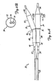
bifurcation 10 which includesparent vessel 12,first branch vessel 14 andsecond branch vessel 16. FIG. 1 also illustrates that abifurcation lesion 18 has developed inbifurcation 10.Lesion 18 illustrates one common bifurcation lesion in that it extends up intoparent vessel 12 and down into bothbranch vessels - FIGS. 2A and 2B illustrate a dilatation and
stent deployment device 20. -
Device 20 includes afirst sheath 22, and a pair of dilatation balloons 24 and 26. Eachdilatation balloon balloon catheter sheath 22. It should also be noted thatsheath 22 can be a separate member preferably fixedly disposed aboutballoon catheters catheters Balloons Balloon 24 preferably includesproximal end 32 anddistal end 34 with anintermediate portion 36 therebetween. The region ofballoon 24 betweenproximal end 32 andintermediate portion 36 preferably forms a smaller diameter (or narrower)balloon segment 38. The region ofballoon 24 betweenintermediate portion 36 anddistal end 34 preferably forms a largerdiameter balloon segment 40. - Similarly,
balloon 26 preferably has aproximal end 42, adistal end 44, and anintermediate portion 46 therebetween. The region betweenproximal end 42 andintermediate region 46 preferably forms a smaller diameter (or narrower)balloon segment 48, while the portion of balloon betweenintermediate region 46 anddistal end 44 preferably forms a largerdiameter balloon segment 50. - As will be described in greater detail later in the specification, smaller
diameter balloon segments parent vessel 12, while largerdiameter balloon segments branch vessels -
Intermediate section 46 ofballoon 26 is simply a necked down diameter reduction area which smoothly transitions the outer diameter ofballoon 26 from the larger diameter ofballoon segment 50 to the smaller diameter ofballoon segment 48. Similarly,intermediate section 36 is a necked down portion which transitions the outer diameter ofballoon 24 from the largediameter balloon segment 40 to the smallerdiameter balloon segment 38. Further,intermediate section 46 preferably (and optionally) includes a preformedbend section 62.Preformed bend section 62 is preferably formed such thatdistal end 44 ofballoon 26 extends away fromdistal end 34 ofballoon 24 at any desired angle α. In one arrangement, α is in a range of approximately 30° - 70°, while in another arrangement, α is in a range of approximately 45° - 60°. In any case, upon inflation ofballoon 26, preformedbend region 62 causesballoon 26 to deform in the shape shown in FIGS. 2A and 6 such that it can more easily findbranch vessel 16, and track guidewire 60 intobranch vessel 16. - FIG. 2B is a cross-sectional end view of
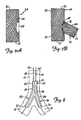
balloon 24 taken alongsection lines 2B-2B in FIG. 2A further illustrating the construction ofballoons balloon 24 will be described, for the sake of clarity.Balloon 24 preferably includes anouter wall 52 of expandable balloon material.Balloon 24 also preferably includes aninner guidewire lumen 54, and aninflation lumen 56. In one arrangement,guidewire lumen 54 andinflation lumen 56 are coaxially aligned withguidewire lumen 54 disposed withininflation lumen 56.Inflation lumen 56 terminates at a proximal region ofballoon 24 whileguidewire lumen 54 extends throughballoon 24 and is bonded to the distal end thereof. In one arrangement, the length from the distal tip ofballoon 24 to the distal end ofsheath 22 measures approximately 25 cm. Bothguidewire lumen 54 andinflation lumen 56 extend fromballoon 24 all the way to a proximal end ofsheath 22, which preferably resides outside the body during dilatation and stent delivery. However, in another arrangement, onlyinflation lumen 56 extends all the way to the proximal end ofsheath 22, whileguidewire lumen 54 is of a monorail construction which has a proximal ostium proximal ofballoon 24, and has a distal ostium in the region of thedistal tip 34 ofballoon 24. In yet another arrangement, the inflation lumens of bothballoons balloons - In any case, both balloons can also have an inflation lumen and a guidewire lumen, so they are suitable for independent inflation, and for tracking of separate guidewires. It should also be noted that, in one arrangement, when balloons 24 and 26 are in the deflated, insertion position, they obtain a low enough profile to both fit within a guide catheter (not shown).
- FIGS. 3-6 illustrate dilatation of
bifurcation 10. FIG. 3 illustrates that, in a first step, twoguidewires bifurcation 10.Guidewire 58 is manipulated such that it is advanced downbranch vessel 14, whileguidewire 60 is manipulated to be advanced downbranch vessel 16. - Once
guidewires device 20 is then advanced overguidewires Device 20 is preferably preloaded, or backloaded, ontoguidewires balloons balloon 24, whileguidewire 60 extends through the guidewire lumen inballoon 26.Sheath 22 andballoons guidewires bifurcation 10. The insertion ofdevice 20 is preferably observed by the treating physician under any suitable visualization technique, such as through the introduction of contrast medium, or fluoroscopy, or the like. - FIG. 5 illustrates that balloons 24 and 26 are then advanced over
guidewires distal tips balloons branch vessels corresponding catheters sheath 22 and move as a unitary member.Balloons bifurcation 10, and the size oflesion 18. - Once balloons 24 and 26 are positioned as shown in FIG. 5, they are inflated to accomplish dilatation of
bifurcation 10. This is illustrated in FIG. 6. FIG. 6 also illustrates that the two smallerdiameter balloon segments parent vessel 12 ofbifurcation 10. In addition, largerdiameter balloon segments branch vessels lesion 18 in those vessels. - Once placed in the position shown in FIG. 6, and inflated, balloons 24 and 26 can be deflated and reinflated any desired number of times, to accomplish optimal dilatation. Once dilatation has been accomplished, balloons 24 and 26 are preferably deflated, and withdrawn proximally over
guidewires - After the dilatation illustrated by FIG. 6, it may be desirable to deploy a stent in
bifurcation 10. FIGS. 7A and 7B illustrate a stent which can be deployed bydevice 20 inbifurcation 10. FIG. 7A illustrates that the bifurcation stent preferably includes afirst stent portion 64.Stent portion 64 can be any suitable, and commercially available stent, such a Palmaz-Schatz stent or an NIR stent.Stent 64 preferably includes a tubularstructural wall 66.Wall 66 preferably has anaperture 68 formed therein, near a midregion ofstent 64, between afirst end 70 and asecond end 72 thereof. FIG. 7B illustrates that the bifurcated stent also preferably includes asecond stent portion 74.Second stent portion 74 preferably has afirst end 76 and asecond end 78, wherein thefirst end 76 is cut at an angle relative to the longitudinal axis ofstent 74, First end 76 is preferably coupled tostent 64 aboutaperture 68, thus forming a bifurcated stent having afirst portion 80 which is configured to reside in the parent vessel, and two dependingportions branch vessels - In another arrangement, the stent is manufactured as one integral stent having a conformation with a main section and two depending leg sections.
- In order to deploy the bifurcated stent illustrated in FIG. 7B, the stent is first preloaded onto device 20 (as shown in FIGS. 8 and 9) such that
first portion 80 is disposed over the smallerdiameter balloon segments balloons portions diameter balloon segments device 20 while theballoons balloons - Next, balloons 24 and 26, (either before or after the bifurcated stent is disposed thereon) are backloaded onto
guidewires Device 20 is then advanced through the vasculature (in the same manner as indicated above with respect to FIGS. 3-5) untilballoons bifurcation 10 in the position shown in FIG. 8.Balloons tubular structure 66 frictionally engages the inner periphery of the lumen walls of bothbranch vessels parent vessel 12. - Thus, it can be seen that
device 20 provides significant advantages over prior bifurcation dilatation and stent deployment techniques. For example,device 20 is capable of dilating bothbranch vessels device 20 is capable of deploying a stent in both branch vessels at the same time. This significantly reduces the likelihood that either of thebranch vessels guidewires branch vessels - FIGS. 10A-10C illustrate a
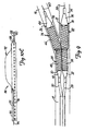
bifurcation dilatation device 86 in accordance with the present invention. FIG. 10B is a cross-sectional view taken along section lines 10B-10B in FIG. 10A and FIG. C is a view rotated 90° about the longitudinal axis relative to the view shown in FIG. 10A.Device 86 includesguidewire sheath 88,catheter 90, andballoon 92.Sheath 88 is preferably a separate member fromcatheter 90 andballoon 92. FIG. 10A also shows bothguidewires Guidewires Guidewire sheath 88 is preferably simply a sheath (typically polyethylene) which is disposed aboutguidewires guidewires bifurcation 10, preferably through a guide catheter (not shown).Balloon 92 preferably includes aproximal end 100 and adistal end 104 and is eccentrically located onshaft 90.Distal end 104 is preferably disposed just proximal of the distal tip ofshaft 90.Balloon 92 and thelumens balloon 92 and then bonding or welding the lumen tube to the balloon, orshaft 90, at appropriate locations. - In an embodiment in which
shaft 90 is an over-the-wire shaft, it is preferably formed of a suitable polymer material. However,shaft 90 can also extend proximally to a stainless steel hypotube shaft (not shown) and be bonded to the stainless steel hypotube shaft at a desirable location. It may also be desirable to have a stainless steel extension, orsupport shaft 95, extending from the hypotube shaft to a regionproximate balloon 92, to provide rigidity to enhance pushability ofshaft 90 andballoon 92. -
Shaft 90 also preferably includes an inflation lumen 93 (shown in FIG. 10B), as well asguidewire sheath lumen 94.Inflation lumen 93 has an opening 97 which communicates with the interior ofballoon 92.Lumen 93 extends proximally alongshaft 90, all the way to the proximal end ofshaft 90 which resides outside the body during dilatation and stent deployment.Guidewire sheath lumen 94, on the other hand, can extend all the way to the proximal end ofshaft 90, or can have a proximal ostium which is disposed just proximal of theproximal end 100 ofballoon 92, and also proximal of theproximal end 98 of slit 96 (described below). -
Shaft 90 includes slit 96 which has aproximal end 98, disposed just proximal ofproximal end 100 ofballoon 92, and adistal end 102 which is coterminous with the distal tip ofballoon 92. In one embodiment, slit 96 is simply a cut or separation made in the wall ofshaft 90. Preferably, the distal end ofslit 96 has a v-cut lead in and the proximal end has a relief hole to inhibit tearing. - As will be described in greater detail with respect to FIGS. 11A-11I,
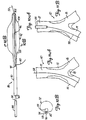
single balloon 92 anddevice 86 can be used to dilate bothbranch vessels bifurcation 10 by alternatively switching from following oneguidewire 58, to following theother guidewire 60, without removal ofdevice 86 from the vessel. Briefly, this is done by first advancingballoon 92 alongguidewire 58, while allowingguidewire 60 to slip throughslit 96 asballoon 92 enters thefirst branch vessel 14. Then,balloon 92 is withdrawn such that bothguidewires guidewire lumen 94.Balloon 92 is then rotated and advanced alongguidewire 60, allowingguidewire 58 to exitguidewire lumen 94 throughslit 96. This allowsballoon 92 to be advanced alongguidewire 60 into theother branch vessel 16 for dilatation of that branch vessel. - More specifically, FIG. 11A illustrates a first step in dilating
bifurcation 10 withdevice 86.Guidewire 58 is first advanced tobifurcation 10, and the lesion inbranch vessel 14 is crossed withguidewire 58. Then, as shown in FIG. 11B,guidewire sheath 88 is advanced overguidewire 58 such that its distal end is disposed just proximal ofbifurcation 10.Guidewire 60 is then advanced throughsleeve 88 and across the lesion inbranch vessel 16. This is indicated in FIG. 11C. - It should be noted that
sleeve 88 can be backloaded or preloaded ontowires sleeve 88 is preferably loaded within the distal end oflumen 94 orcatheter 90, and bothguidewires sleeve 88 inguidewire lumen 94 ofshaft 90. Onceguidewires sleeve 88, are in the positions shown in FIG. 11C,device 86 is advanced overguidewires distal tip 102 ofslit 96 is closely proximate, or adjacent, the distal tip ofsleeve 88. This is illustrated in FIG. 11D. It can be seen that the distal tip ofsleeve 88 is positioned at a point whereguidewires branch vessels -
Device 86 is then rotated such that slit 96 engageswire 58.Device 86 is then advanced distally whilewires guidewire lumen 94 to trackguidewire 60, while allowingguidewire 58 to escape fromguidewire lumen 94 alongslit 96. Thus, asdevice 86 is advanced distally, the distal end ofdevice 86 follows guidewire 60 intobranch vessel 16 ofbifurcation 10. -
Device 86 is further advanced alongguidewire 60 to a position whereballoon 92 is sufficiently disposed withinbranch vessel 16. This is indicated in FIG. 11E. - Once
balloon 92 is positioned withinbranch vessel 16,balloon 92 is inflated, as shown in FIG. 11F. This dilatesbranch vessel 16. Of course,balloon 92 can be inflated and deflated any desired number of times, as is well known, in order to accomplish desired dilatation ofbranch vessel 16. -
Balloon 92 is then deflated anddevice 16 is withdrawn proximally such that thedistal tip 102 ofslit 96 is again closely proximate the distal tip ofsleeve 88 as shown in FIG. 11G. FIG. 11G also illustrates that, oncetip 102 is withdrawn just proximal of the distal tip ofsleeve 88, bothguidewires guidewire lumen 94, sincesleeve 88 also resides coaxially withinguidewire lumen 94. - In order to dilate the lesion in
branch vessel 14,device 86 is again rotated untilslit 96 is in position to engageguidewire 60.Device 86 is then advanced distally, while holdingguidewires guidewire lumen 94 to track alongguidewire 58, while allowingguidewire 60 to escape throughslit 96.Device 86 is advanced further distally untilballoon 92 resides sufficiently withinbranch vessel 14, as illustrated in FIG. 11H. -
Balloon 92 is then inflated, as shown in FIG. 11I, in order to dilate thebranch vessel 14. Of course, as described with respect tobranch vessel 16,balloon 92 can be inflated and deflated a desired number of times in order to accomplish sufficient dilatation.Balloon 92 is then deflated, anddevice 86 is withdrawn from the vasculature. Of course,device 86 can be withdrawn from the vasculature, along withguidewires - As described in the background portion of the specification, dilatation of one of branching
vessels vessels - FIGS. 12A-12C illustrate a
perfusion tube 106 in accordance with one aspect of the present invention.Perfusion tube 106, in one preferred embodiment, is formed of a generallytubular structure 108 which is made of polyethylene, or another suitable polymer material.Tubular structure 108 is attached, such as by welding, adhesive, or another suitable bonding technique, to apush wire 110 which is made of stainless steel, or another suitable material.Tubular member 108 also includes a slit, or elongate aperture, 112 which extends from aproximal end 114 thereof to adistal end 116. FIG. 12B is an end view oftubular member 108 and illustrates thatslit 112 extends all the way through the tubular wall ofmember 108.Tubular member 108 is preferably formed of a material with sufficient rigidity that thetubular member 108 will not roll up on itself about its longitudinal axis. Such rolling may be further inhibited by providingslit 112 at an angle relative to the longitudinal axis oftubular member 108, as shown in FIG. 12A. -
Perfusion tube 106 can be used in much the same way asdevice 86 described with respect to FIGS. 10A-11I. In other words,perfusion tube 106 can be used to selectively track one ofguidewires branch vessels guidewires other branch vessels perfusion tube 106 from the vasculature. - FIG. 12C illustrates that, in a preferred embodiment, after
sheath 88 is advanced to the position shown in FIG. 11B,perfusion tube 106 is advanced oversheath 88 and rotated such thatslit 112 engagesguidewire 58.Perfusion tube 106 is then advanced further distally, by pushing onpush wire 110, such that the lumen withinperfusion tube 106 tracks alongguidewire 60 whileguidewire 58 is allowed to escape throughslit 112. Of course,perfusion tube 106 can be positioned to trackguidewire 58 for placement withinbranch vessel 14. In order to accomplish such placement,push wire 110 is pulled proximally such thatperfusion tube 106 is withdrawn back oversleeve 88 such that bothguidewires tubular member 108.Perfusion tube 106 is then rotated such thatslit 112 engagesguidewire 60, andperfusion tube 106 is again advanced. This time, the lumen inperfusion tube 106 tracks overguidewire 58 while allowingguidewire 60 to escape such thatperfusion tube 106 can be advanced intobranch vessel 14. - It should also be noted that
perfusion tube 106 can easily be used withdevice 86. This is illustrated in FIGS. 13A-13C. - In one preferred embodiment,
perfusion tube 106 is loaded ontosleeve 88 distally ofdevice 86. Of course,perfusion tube 106 could also be loaded ontosleeve 88 proximally ofdevice 86. However, for the sake of expedience, only the embodiment in whichperfusion tube 106 is loaded distally will be described in detail. - In any case,
perfusion tube 106 is preferably advanced oversleeve 88 until thedistal end 116 ofperfusion tube 106 is closely proximate the distal end ofsleeve 88. This is illustrated in FIG. 3A. - Then,
perfusion tube 106 is rotated such thatslit 112 engageswire 58.Perfusion tube 106 is then advanced such that it tracks guidewire 60 intobranch vessel 16 whileguidewire 58 is allowed to escape throughslit 112. -
Device 86 is then advanced distally until its distal end is closely proximate the distal end ofsleeve 88. As described with respect to FIGS. 11A-11I,device 86 is rotated to a position where slit 96 engageswire 60.Device 86 is advanced distally such thatguidewire lumen 94 tracks guidewire 58, allowingguidewire 60 to escape throughslit 96. - By continuing to advance
perfusion tube 106 anddevice 86 as described above,perfusion tube 106 will reside inbranch vessel 16 whileballoon 92 ofdevice 86 will reside inbranch vessel 14. This is illustrated in FIG. 13B.Balloon 92 can then be inflated to accomplish dilatation ofbranch vessel 14 without collapsingbranch vessel 16. - Similarly, both devices can then be withdrawn proximally (while holding
guidewires sleeve 88 in place) to the position shown in FIG. 13A.Perfusion tube 106 is then rotated such thatslot 112 engageswire 60 and so thatperfusion tube 106 can be advanced withinbranch vessel 14.Device 86 is positioned such that slit 96 engages guidewire 58 soballoon 92 can be advanced withinbranch vessel 16. This is indicated in FIG. 13C.Balloon 92 is then inflated to dilatebranch vessel 16. Sinceperfusion tube 106 now resides inbranch vessel 14, dilatation can be accomplished without collapsingbranch vessel 14. - In another preferred embodiment,
perfusion tube 106 can be used to accomplish dilatation as well. In that embodiment,tubular member 108 has a lumen therethrough which is sufficiently sized to receiveballoon 92 in the deflated position. Bothdevice 96 andperfusion tube 106 are rotated such that slit 96 andslot 112 both engage the same guidewire (such asguidewire 60 illustrated in FIG. 13D).Balloon 92 is placed within the lumen ofperfusion tube 106 in the deflated position, and bothballoon 92 andperfusion tube 106 are placed in the same branch vessel (such as branch vessel 14).Balloon 92 is then inflated usingperfusion tube 106 to exert outward pressure to dilate the chosen branch vessel. Of course, it should also be noted that a second perfusion tube can also be used and inserted in the opposite branch vessel to prevent that branch vessel from collapsing during dilation. - FIG. 14A illustrates a dilatation and
stent deployment device 120.Device 120 is illustrated as an over-the-wire catheter but could be implemented in a monorail construction as well.Device 120 includes acatheter shaft 122 andballoon 124.Balloon 124 includesproximal end 126,distal end 128 andintermediate portion 130.Shaft 122 includesinflation lumen 132,first guidewire lumen 134, andsecond guidewire lumen 136. In one arrangement theinflation lumen 132 andfirst guidewire lumen 134 are coaxially aligned withguidewire lumen 134 disposed withininflation lumen 132.Inflation lumen 132 is preferably in fluid communication with the interior ofballoon 124 throughaperture 138. A proximal end ofshaft 122 is thus coupleable to a source of fluid pressure for delivering fluid under pressure to, and withdrawing fluid from, the interior ofballoon 124. -
First guidewire lumen 134 is preferably configured as a conventional guidewire lumen which extends from the proximal end ofcatheter shaft 122 through the distal end of catheter shaft 122 (distal of balloon 124). This allowscatheter shaft 122 to be advanced overguidewire - In FIG. 14A, the
second guidewire lumen 136 also extends from the proximal end ofcatheter shaft 122 to a distal region ofcatheter shaft 122, but not all the way to the distal tip ofshaft 122. Rather, the distal opening ofguidewire lumen 136 is disposed inintermediate region 130 ofballoon 124. Thus, guidewire 58 or 60 (guidewire 60 illustrated in FIG. 14A) exits the distal ostium ofguidewire lumen 136 at theintermediate portion 130 ofballoon 124. - It should also be noted that
device 120 can be formed in a monorail structure in which the proximal opening of each ofguidewire lumens shaft 122. In that arrangement,guidewire lumens proximal end 126 ofballoon 124. - FIG. 14B shows a greatly enlarged portion of
second guidewire lumen 136 inregion 140 ofballoon 124. FIG. 14B illustrates that, in one arrangement, acoil 142 is disposed withinsecond guidewire lumen 136, at least inregion 140proximate balloon 124.Coil 142 can be any suitable material, such as stainless steel, surlyn, polyester, or another suitable material. - FIG. 14C illustrates a cross-sectional view of a portion of
device 120 taken alongsection lines 14C-14C in FIG. 14A, and illustrates one preferred method of formingballoon portion 124 ofdevice 120. A coextruded tube of balloon material is first provided with a pair of lumens therein. Interior pressure is then exerted on the portion ofguidewire lumen 136 which extends throughballoon 124. This causesguidewire lumen 136 to expand.Coil 142 is then placed within the expandedlumen 136 and that region of the balloon material is heated to shrink the balloon material down overcoil 142 and thereby frictionallysecure coil 142 withinlumen 136. Ahole 143 is then drilled in the side of the structural wall portion ofballoon 124 in order to form the distal ostium ofguidewire lumen 136. - Next, interior pressure is exerted on the interior of
lumen 144 to expandlumen 144, which becomes the interior ofballoon 124.Shaft 122 is then inserted throughlumen 144 and thedistal end 128 ofballoon 124 is secured (such as with adhesive or through welding) to the distal end ofshaft 122. Theproximal end 126 ofballoon 124 is then also secured toshaft 122 such that the portion oflumen 136 throughballoon 124 communicates with the portion oflumen 136 onshaft 122. The remainder of theproximal shaft 126 ofballoon 124 is then secured about the periphery ofshaft 122 to form a fluid tight seal such that theinterior 144 ofballoon 124 can be inflated by providing pressurized fluid throughinflation lumen 132. - Since
coil 142 resides withinlumen 136, and sincelumen 136 is eccentrically arranged relative to the longitudinal axis ofballoon 124, it has been observed that inflation ofballoon 124 can causeballoon 124 to arc, or form a convex shape in a longitudinal direction, aboutcoil 142 andlumen 136. This is caused because the resistance to inflation on the side ofballoon 124 containingcoil 142 is greater than the resistance to inflation on the opposite side ofballoon 124. Therefore, an extra bead or portion ofballoon material 146 is disposed during the extrusion process in the balloon wall on an opposite ofcoil 142. This causes a balancing in resistance to the inflation force and thus reduces or eliminates any deformation ofballoon 124 upon inflation. - FIG. 14D illustrates operation of
device 120.Guidewires lesion 18 and intobranch vessels device 120 is either backloaded, or preloaded, ontoguidewires guidewires lumen 134 and the other is disposed withinlumen 136. In the illustration of FIG. 14D, guidewire 58 is disposed withinlumen 134, whileguidewire 60 is disposed withinlumen 136. -
Device 120 is then advanced distally tobifurcation 10. Asdevice 120 is advanced distally, thedistal end 128 ofballoon 124 tracks alongguidewire 58, becauseguidewire lumen 134 extends out the distal end ofshaft 122. This causes thedistal end 128 ofballoon 124 to extend withinbranch vessel 14.Balloon 124 is then inflated to dilatebranch vessel 14. It should also be noted, of course, thatballoon 124 can be used to deploy a stent inbranch vessel 14 as well, and that it can be advanced into smaller vessels as well. - FIG. 14D illustrates stent 150 disposed on the distal end of
balloon 124. A stent such asstent portion 64 could also be disposed onballoon 124 withguidewire 60 extending out throughaperture 68 in the wall structure ofstent 64. In any case, prior to loadingguidewires device 120,stent 156 is preferably crimped down over the distal portion ofballoon 124 in a known manner.Balloon 124 is then loaded onto the guidewires and advanced to the position shown in FIG. 14D.Balloon 124 is then inflated to drivestent 156 to its expanded, deployed position in which it frictionally engages the inner wall of the lumen ofbranch vessel 14. - In order to dilate, or deploy a stent in,
branch vessel 16,device 120 is withdrawn proximally and is reoriented such thatguidewire 58 is disposed withinlumen 136, and guidewire 60 is disposed withinlumen 134.Device 120 is then advanced distally until thedistal tip 128 ofballoon 124 is disposed within branch vessel 16 (or in another distal vessel). Again,balloon 124 is inflated to either dilatebranch vessel 16 or to deploy a stent therein. - As FIG. 14D illustrates, the proximal portion of
balloon 124 will still reside inparent vessel 12 while the distal portion ofballoon 124 is in either of thebranch vessels balloon 124 can be used to cause simultaneous dilation ofparent vessel 12. - FIGS. 15A and 15B illustrate another method of forming
lumen 136 inballoon 124. Rather than providing a separate lumen within the balloon wall structure ofballoon 124, as illustrated in FIGS. 14A-14D, a second balloon orcavity 160 is formed withinballoon 124 which comprises the portion ofguidewire lumen 136 withinballoon 124. -
Balloon 124 is first provided. Then, a portion of balloon material is placed withinballoon 124, and is inflated to form a second balloon, or cavity, 160 withinballoon 124.Balloon 160 is then attached, such as through adhesive, welding or another suitable process, to the interior side wall ofballoon 124. Anaperture 126 is then drilled in the exterior wall ofballoon 124 and intocavity 160, to form the distal ostium ofguidewire lumen 136. In addition, the proximal end ofballoon 160 is secured about the tube forming the proximal portion ofguidewire lumen 136. - FIG. 16 illustrates another arrangement of a dilatation or stent deployment device in which the distal end of
guidewire lumen 136 is formed in a different manner. In FIG. 16,sheath 164 is disposed about the proximal, exterior surface ofballoon 124.Sheath 164 is secured to the exterior surface ofballoon 124 throughout the entire exterior periphery of the proximal end ofballoon 124 except at aregion 166 which is in alignment withguidewire lumen 136. In that region,sheath 164 is not attached to the exterior surface ofballoon 124. The space between the exterior surface ofballoon 124 and the interior surface ofsheath 164 inregion 166 defines the distal region ofguidewire lumen 136. It should also be noted that a tube, or other suitable material, can be inserted betweenballoon 124 andsheath 164 in the area oflumen 166 in order to provide additional structural integrity to the lumen. - FIG. 17 illustrates yet another device 170. Device 170 is similar to the device illustrated in FIG. 15A. However, rather than forming a second balloon within the interior of
balloon 124 in order to provide the distal region ofguidewire lumen 136, device 170 illustrated in FIG. 17 includes asecond balloon 168 formed on the exterior ofballoon 124.Balloon 168 is coupled, bytransition shaft 172, to the proximal portion ofguidewire lumen 136.Balloon 168 is formed in a conventional manner, and is simply provided to define the distal region of thesecond guidewire lumen 136 such that it has a distal ostium in the intermediate portion ofballoon 124.Balloon 168 could also be made longer such that its distal end resides in the branch vessel. - FIG. 18 illustrates yet another
device 180.Device 180 is similar to device 170 shown in FIG. 17, and similar items are similarly numbered. However, rather than providing asecond balloon 168 to provide the distal portion ofguidewire lumen 136,device 180 simply provides atube 182 which is connected toguidewire lumen 136 inshaft 122.Tube 182 is preferably a polyethylene tube which is a free floating tube in that it is not attached to the exterior surface ofballoon 124.Tube 182 has its distal tip defining the distal opening ofguidewire lumen 136 in the intermediate region ofballoon 124.Tube 182 could also be made longer such that its distal opening resides in the branch vessel. - Thus, it can be seen that the present invention provides significant advantages over prior systems for performing dilatation and stent deployment at bifurcations. The present invention provides a system for simultaneously tracking two guidewires which can be positioned in the branch vessels of the bifurcation, and maintained in those branch vessels throughout the entire dilation and stent deployment. In addition, the present invention provides a system with which dilation and stent deployment can be performed in both branch vessels, without collapsing either. This reduces the cumbersome nature of performing dilation and stent deployment at bifurcations, and also enhances the efficiency of dilation and stent deployment performed in those regions.
- Although the present invention has been described with reference to preferred embodiments, workers skilled in the art will recognize that changes may be made in form and detail without departing from the scope of the claims.
Claims (7)
- A system for treating a lesion at a bifurcation (10) in a body, the bifurcation bifurcating a parent vessel (12) into first (14) and second (16) branch vessels, the system comprising:a generally tubular member (90) having a proximal end and a distal end and defining a guidewire lumen (94) therein, the guidewire lumen sized to receive first (58) and second (60) guidewires, characterised in that the generally tubular member has an elongate aperture (96) extending from the distal end thereof proximally and being configured to engage a selected one (58) of the first and second guidewires such that advancement of the generally tubular member after the elongate aperture is engaged with the selected one of the first and second guidewires causes the lumen to track the unselected guidewire and causes the selected guidewire to exit the guidewire lumen through the elongate aperture; andan elongate member (90) having a distal end coupled to the proximal end of the generally tubular member and having a proximal end, the elongate member having sufficient length to extend from the bifurcation to a region external to the body.
- The system of claim 1 wherein the generally tubular member (90) comprises: a generally tubular wall defining the guidewire lumen (94), the elongate aperture (96) severing the wall.
- The system of claim 1 wherein the generally tubular member comprises a distal region of the elongate member (90), the elongate member further including an inflation lumen (93) extending from the proximal end thereof to the distal end of the generally tubular member (90).
- The system of claim 3 and further comprising: an inflatable member (92) disposed on the generally tubular member (90) and having an interior in fluid communication with the inflation lumen (93); and the elongate aperture (96) extending from the distal end of the generally tubular member proximally to a region of the elongate member proximate a proximal end of the inflatable member.
- The system of claim 4 wherein the guidewire lumen (94) has a proximal ostium disposed proximate a proximal end of the inflatable member (92).
- The system of claim 1 and further comprising: a guidewire sleeve (88) having a lumen therein sized to slidably receive the first (58) and second (60) guidewires and having an outer periphery sized to slidably fit within the guidewire lumen (94).
- The system of claim 1 wherein the guidewire lumen (94) extends through the elongate member (90) to the proximal end thereof.
Applications Claiming Priority (3)
| Application Number | Priority Date | Filing Date | Title |
|---|---|---|---|
| US35642 | 1998-03-05 | ||
| US09/035,642 US6099497A (en) | 1998-03-05 | 1998-03-05 | Dilatation and stent delivery system for bifurcation lesions |
| PCT/US1999/003988 WO1999044539A2 (en) | 1998-03-05 | 1999-02-24 | Dilatation and stent delivery system for bifurcation lesions |
Publications (2)
| Publication Number | Publication Date |
|---|---|
| EP1065994A2 EP1065994A2 (en) | 2001-01-10 |
| EP1065994B1 true EP1065994B1 (en) | 2004-11-17 |
Family
ID=21883919
Family Applications (1)
| Application Number | Title | Priority Date | Filing Date |
|---|---|---|---|
| EP99908407A Expired - Lifetime EP1065994B1 (en) | 1998-03-05 | 1999-02-24 | Dilatation and stent delivery system for bifurcation lesions |
Country Status (7)
| Country | Link |
|---|---|
| US (3) | US6099497A (en) |
| EP (1) | EP1065994B1 (en) |
| JP (1) | JP4445125B2 (en) |
| AT (1) | ATE282374T1 (en) |
| CA (1) | CA2321040C (en) |
| DE (1) | DE69921976T2 (en) |
| WO (1) | WO1999044539A2 (en) |
Families Citing this family (260)
| Publication number | Priority date | Publication date | Assignee | Title |
|---|---|---|---|---|
| US6936025B1 (en) | 1992-05-19 | 2005-08-30 | Bacchus Vascular, Inc. | Thrombolysis device |
| US5713848A (en) * | 1993-05-19 | 1998-02-03 | Dubrul; Will R. | Vibrating catheter |
| FR2733682B1 (en) * | 1995-05-04 | 1997-10-31 | Dibie Alain | ENDOPROSTHESIS FOR THE TREATMENT OF STENOSIS ON BIFURCATIONS OF BLOOD VESSELS AND LAYING EQUIPMENT THEREFOR |
| US6692483B2 (en) | 1996-11-04 | 2004-02-17 | Advanced Stent Technologies, Inc. | Catheter with attached flexible side sheath |
| US7591846B2 (en) | 1996-11-04 | 2009-09-22 | Boston Scientific Scimed, Inc. | Methods for deploying stents in bifurcations |
| US6835203B1 (en) | 1996-11-04 | 2004-12-28 | Advanced Stent Technologies, Inc. | Extendible stent apparatus |
| US6325826B1 (en) | 1998-01-14 | 2001-12-04 | Advanced Stent Technologies, Inc. | Extendible stent apparatus |
| US6596020B2 (en) | 1996-11-04 | 2003-07-22 | Advanced Stent Technologies, Inc. | Method of delivering a stent with a side opening |
| US6599316B2 (en) | 1996-11-04 | 2003-07-29 | Advanced Stent Technologies, Inc. | Extendible stent apparatus |
| US8211167B2 (en) | 1999-12-06 | 2012-07-03 | Boston Scientific Scimed, Inc. | Method of using a catheter with attached flexible side sheath |
| US7341598B2 (en) | 1999-01-13 | 2008-03-11 | Boston Scientific Scimed, Inc. | Stent with protruding branch portion for bifurcated vessels |
| US6682536B2 (en) | 2000-03-22 | 2004-01-27 | Advanced Stent Technologies, Inc. | Guidewire introducer sheath |
| US6261260B1 (en) * | 1997-04-15 | 2001-07-17 | Terumo Kabushiki Kaisha | Balloon for medical tube and medical tube equipped with the same |
| US6099497A (en) * | 1998-03-05 | 2000-08-08 | Scimed Life Systems, Inc. | Dilatation and stent delivery system for bifurcation lesions |
| US20050131453A1 (en) * | 1998-03-13 | 2005-06-16 | Parodi Juan C. | Apparatus and methods for reducing embolization during treatment of carotid artery disease |
| US6645222B1 (en) * | 1998-05-13 | 2003-11-11 | Arteria Medical Science, Inc. | Puncture resistant branch artery occlusion device and methods of use |
| US6908474B2 (en) * | 1998-05-13 | 2005-06-21 | Gore Enterprise Holdings, Inc. | Apparatus and methods for reducing embolization during treatment of carotid artery disease |
| US6117117A (en) * | 1998-08-24 | 2000-09-12 | Advanced Cardiovascular Systems, Inc. | Bifurcated catheter assembly |
| US7655030B2 (en) | 2003-07-18 | 2010-02-02 | Boston Scientific Scimed, Inc. | Catheter balloon systems and methods |
| US20050060027A1 (en) * | 1999-01-13 | 2005-03-17 | Advanced Stent Technologies, Inc. | Catheter balloon systems and methods |
| US8257425B2 (en) | 1999-01-13 | 2012-09-04 | Boston Scientific Scimed, Inc. | Stent with protruding branch portion for bifurcated vessels |
| DE60021173T2 (en) | 1999-01-27 | 2006-04-27 | Boston Scientific Ltd., St Michael | BIFURKATIONSSTENTEINFÜHRSYSTEM |
| EP1547546B1 (en) * | 1999-01-27 | 2010-11-03 | Boston Scientific Limited | Bifurcation stent delivery system |
| DE19921788A1 (en) * | 1999-05-11 | 2000-11-16 | Jomed Implantate Gmbh | Device for implanting vascular supports |
| US7387639B2 (en) * | 1999-06-04 | 2008-06-17 | Advanced Stent Technologies, Inc. | Short sleeve stent delivery catheter and methods |
| US6689156B1 (en) | 1999-09-23 | 2004-02-10 | Advanced Stent Technologies, Inc. | Stent range transducers and methods of use |
| WO2001035715A2 (en) * | 1999-11-18 | 2001-05-25 | Petrus Besselink | Method for placing bifurcated stents |
| US6299595B1 (en) * | 1999-12-17 | 2001-10-09 | Advanced Cardiovascular Systems, Inc. | Catheters having rapid-exchange and over-the-wire operating modes |
| US6482172B1 (en) | 2000-02-09 | 2002-11-19 | Jeffrey J. Thramann | Flow-by channel catheter and method of use |
| ITMI20020860A1 (en) * | 2002-04-22 | 2003-10-22 | E V R Endovascular Res Es S A | ENDOLUMINAL DEVICE TO TRANSPORT AND DISPLAY AN EXPANDABLE ENDOLUMINAL PROSTHESIS |
| AU3726401A (en) * | 2000-02-18 | 2001-08-27 | E V R Endovascular Res Es S A | Endolumenal device for delivering and deploying an endolumenal expandable prosthesis |
| US20120089220A1 (en) * | 2000-02-18 | 2012-04-12 | E.V.R. Endovascular Researches S.A. | Microcatheter |
| US6482211B1 (en) * | 2000-07-31 | 2002-11-19 | Advanced Cardiovascular Systems, Inc. | Angulated stent delivery system and method of use |
| US7101391B2 (en) * | 2000-09-18 | 2006-09-05 | Inflow Dynamics Inc. | Primarily niobium stent |
| US6485512B1 (en) * | 2000-09-27 | 2002-11-26 | Advanced Cardiovascular Systems, Inc. | Two-stage light curable stent and delivery system |
| US6461326B1 (en) | 2000-10-26 | 2002-10-08 | Scimed Life Systems, Inc. | Fluorescent dyed adhesive for bonding various components in a medical device |
| US6582394B1 (en) * | 2000-11-14 | 2003-06-24 | Advanced Cardiovascular Systems, Inc. | Stent and catheter assembly and method for treating bifurcated vessels |
| US6595980B1 (en) | 2001-02-23 | 2003-07-22 | Coaxia, Inc. | Devices and methods for preventing distal embolization using flow reversal by occlusion of the brachiocephalic artery |
| AU2002250189A1 (en) | 2001-02-26 | 2002-09-12 | Scimed Life Systems, Inc. | Bifurcated stent and delivery system |
| US6602225B2 (en) * | 2001-02-28 | 2003-08-05 | Scimed Life Systems, Inc | Substantially circular catheter assembly |
| US8337540B2 (en) * | 2001-05-17 | 2012-12-25 | Advanced Cardiovascular Systems, Inc. | Stent for treating bifurcations and method of use |
| US8617231B2 (en) * | 2001-05-18 | 2013-12-31 | Boston Scientific Scimed, Inc. | Dual guidewire exchange catheter system |
| US6746466B2 (en) | 2001-05-22 | 2004-06-08 | Scimed Life Systems, Inc. | Method and apparatus for managing multiple guidewires |
| US6533800B1 (en) * | 2001-07-25 | 2003-03-18 | Coaxia, Inc. | Devices and methods for preventing distal embolization using flow reversal in arteries having collateral blood flow |
| JP4460289B2 (en) * | 2001-08-23 | 2010-05-12 | シー. ガム、ダレル | Catheter assembly |
| GB0130745D0 (en) * | 2001-12-21 | 2002-02-06 | Cathnet Science Holding As | Balloon catheter assembly |
| JP4229621B2 (en) | 2002-03-05 | 2009-02-25 | 修 加藤 | Chemical injection catheter |
| AU2003216517A1 (en) * | 2002-03-07 | 2003-09-22 | Cordis Corporation | Iliac bifurcation balloon catheter |
| US20060253480A1 (en) * | 2002-04-06 | 2006-11-09 | Staples Peter E | Collaborative design process for a design team, outside suppliers, and outside manufacturers |
| EP1369097A1 (en) * | 2002-06-07 | 2003-12-10 | CathNet-Science Holding A/S | Balloon catheter assembly |
| US7717934B2 (en) | 2002-06-14 | 2010-05-18 | Ev3 Inc. | Rapid exchange catheters usable with embolic protection devices |
| US6761734B2 (en) | 2002-07-22 | 2004-07-13 | William S. Suhr | Segmented balloon catheter for stenting bifurcation lesions |
| WO2004026183A2 (en) | 2002-09-20 | 2004-04-01 | Nellix, Inc. | Stent-graft with positioning anchor |
| US7367989B2 (en) * | 2003-02-27 | 2008-05-06 | Scimed Life Systems, Inc. | Rotating balloon expandable sheath bifurcation delivery |
| US7314480B2 (en) * | 2003-02-27 | 2008-01-01 | Boston Scientific Scimed, Inc. | Rotating balloon expandable sheath bifurcation delivery |
| JP4272905B2 (en) | 2003-03-06 | 2009-06-03 | 修 加藤 | Chemical injection device |
| US8083791B2 (en) | 2003-04-14 | 2011-12-27 | Tryton Medical, Inc. | Method of treating a lumenal bifurcation |
| US7717953B2 (en) | 2004-10-13 | 2010-05-18 | Tryton Medical, Inc. | Delivery system for placement of prosthesis at luminal OS |
| US7758630B2 (en) | 2003-04-14 | 2010-07-20 | Tryton Medical, Inc. | Helical ostium support for treating vascular bifurcations |
| US7972372B2 (en) | 2003-04-14 | 2011-07-05 | Tryton Medical, Inc. | Kit for treating vascular bifurcations |
| US7481834B2 (en) | 2003-04-14 | 2009-01-27 | Tryton Medical, Inc. | Stent for placement at luminal os |
| US8109987B2 (en) | 2003-04-14 | 2012-02-07 | Tryton Medical, Inc. | Method of treating a lumenal bifurcation |
| US7731747B2 (en) | 2003-04-14 | 2010-06-08 | Tryton Medical, Inc. | Vascular bifurcation prosthesis with multiple thin fronds |
| JP4212949B2 (en) | 2003-05-06 | 2009-01-21 | 朝日インテック株式会社 | Chemical injection device |
| US20040254528A1 (en) * | 2003-06-12 | 2004-12-16 | Adams Daniel O. | Catheter with removable wire lumen segment |
| US7604621B2 (en) * | 2003-07-30 | 2009-10-20 | Boston Scientific Scimed, Inc. | Bifurcated stent delivery system |
| US7959665B2 (en) * | 2003-07-31 | 2011-06-14 | Abbott Cardiovascular Systems Inc. | Intravascular stent with inverted end rings |
| US8298280B2 (en) | 2003-08-21 | 2012-10-30 | Boston Scientific Scimed, Inc. | Stent with protruding branch portion for bifurcated vessels |
| EP1691719B1 (en) * | 2003-10-14 | 2016-09-14 | Cook Medical Technologies LLC | Introducer for an iliac side branch device |
| US7998186B2 (en) | 2003-10-14 | 2011-08-16 | William A. Cook Australia Pty. Ltd. | Introducer for a side branch device |
| US7645296B2 (en) * | 2003-10-16 | 2010-01-12 | Minvasys | Catheter system for protected angioplasty and stenting at a carotid bifurcation |
| US9278015B2 (en) * | 2003-10-16 | 2016-03-08 | Minvasys | Catheter system for stenting and drug treatment of bifurcated vessels |
| US7641684B2 (en) * | 2003-10-16 | 2010-01-05 | Minvasys, Sa | Catheter system for stenting bifurcated vessels |
| US7695508B2 (en) * | 2003-10-16 | 2010-04-13 | Minvasys Sa | Catheter system for stenting bifurcated vessels |
| EP1680170B1 (en) * | 2003-10-16 | 2012-01-25 | Minvasys | Catheter system for stenting bifurcated vessels |
| US7344557B2 (en) | 2003-11-12 | 2008-03-18 | Advanced Stent Technologies, Inc. | Catheter balloon systems and methods |
| US20050101968A1 (en) * | 2003-11-12 | 2005-05-12 | Dadourian Daniel G. | Ostial locator device and methods for transluminal interventions |
| US20050125050A1 (en) * | 2003-12-04 | 2005-06-09 | Wilson Cook Medical Incorporated | Biliary stent introducer system |
| US7686841B2 (en) * | 2003-12-29 | 2010-03-30 | Boston Scientific Scimed, Inc. | Rotating balloon expandable sheath bifurcation delivery system |
| US7922753B2 (en) * | 2004-01-13 | 2011-04-12 | Boston Scientific Scimed, Inc. | Bifurcated stent delivery system |
| US20070038283A1 (en) * | 2004-02-06 | 2007-02-15 | Mustapha Jihad A | Ostial stent and balloon |
| US8012192B2 (en) * | 2004-02-18 | 2011-09-06 | Boston Scientific Scimed, Inc. | Multi-stent delivery system |
| US7225518B2 (en) | 2004-02-23 | 2007-06-05 | Boston Scientific Scimed, Inc. | Apparatus for crimping a stent assembly |
| US7744619B2 (en) | 2004-02-24 | 2010-06-29 | Boston Scientific Scimed, Inc. | Rotatable catheter assembly |
| US7922740B2 (en) | 2004-02-24 | 2011-04-12 | Boston Scientific Scimed, Inc. | Rotatable catheter assembly |
| US7766951B2 (en) * | 2004-03-04 | 2010-08-03 | Y Med, Inc. | Vessel treatment devices |
| US8007528B2 (en) | 2004-03-17 | 2011-08-30 | Boston Scientific Scimed, Inc. | Bifurcated stent |
| WO2005096994A1 (en) * | 2004-03-31 | 2005-10-20 | Wilson-Cook Medical Inc. | Stent introducer system |
| ATE499905T1 (en) * | 2004-05-06 | 2011-03-15 | Invatec Srl | CATHETER FOR TREATMENT OF BIRCHS |
| EP1789126A4 (en) * | 2004-05-21 | 2008-03-12 | Minvasys Sa | Guidewire separator device and method of use |
| JP5054524B2 (en) | 2004-06-08 | 2012-10-24 | アドバンスド ステント テクノロジーズ, インコーポレイテッド | Stent with protruding branch for branch pipe |
| US8048145B2 (en) | 2004-07-22 | 2011-11-01 | Endologix, Inc. | Graft systems having filling structures supported by scaffolds and methods for their use |
| WO2006012567A2 (en) * | 2004-07-22 | 2006-02-02 | Nellix, Inc. | Methods and systems for endovascular aneurysm treatment |
| US20060064064A1 (en) * | 2004-09-17 | 2006-03-23 | Jang G D | Two-step/dual-diameter balloon angioplasty catheter for bifurcation and side-branch vascular anatomy |
| US20060069323A1 (en) * | 2004-09-24 | 2006-03-30 | Flowmedica, Inc. | Systems and methods for bi-lateral guidewire cannulation of branched body lumens |
| US7635383B2 (en) | 2004-09-28 | 2009-12-22 | Boston Scientific Scimed, Inc. | Rotating stent delivery system for side branch access and protection and method of using same |
| JP4821947B2 (en) * | 2004-10-19 | 2011-11-24 | 朝日インテック株式会社 | Chemical injection device |
| US9427340B2 (en) | 2004-12-14 | 2016-08-30 | Boston Scientific Scimed, Inc. | Stent with protruding branch portion for bifurcated vessels |
| CN101102728B (en) * | 2005-01-10 | 2011-06-22 | 曲利姆医疗股份有限公司 | Stand with self-deployable portion |
| US9101500B2 (en) * | 2005-01-10 | 2015-08-11 | Trireme Medical, Inc. | Stent with self-deployable portion having wings of different lengths |
| US8480629B2 (en) | 2005-01-28 | 2013-07-09 | Boston Scientific Scimed, Inc. | Universal utility board for use with medical devices and methods of use |
| JP2006223338A (en) * | 2005-02-15 | 2006-08-31 | Humed Co Ltd | Catheter |
| WO2006089178A2 (en) * | 2005-02-18 | 2006-08-24 | Ev3 Inc. | Rapid exchange catheters and embolic protection devices |
| US7922754B2 (en) * | 2005-04-18 | 2011-04-12 | Trireme Medical, Inc. | Apparatus and methods for delivering prostheses to luminal bifurcations |
| US20060259009A1 (en) * | 2005-05-12 | 2006-11-16 | Medtronic Vascular, Inc. | Guidewire loader for bifurcated vessel |
| WO2006127825A1 (en) * | 2005-05-23 | 2006-11-30 | Incept Llc | Apparatus and methods for locating an ostium of a vessel |
| US8608789B2 (en) | 2005-05-24 | 2013-12-17 | Trireme Medical, Inc. | Delivery system for bifurcation stents |
| US8480728B2 (en) | 2005-05-26 | 2013-07-09 | Boston Scientific Scimed, Inc. | Stent side branch deployment initiation geometry |
| US8317855B2 (en) | 2005-05-26 | 2012-11-27 | Boston Scientific Scimed, Inc. | Crimpable and expandable side branch cell |
| US7666220B2 (en) | 2005-07-07 | 2010-02-23 | Nellix, Inc. | System and methods for endovascular aneurysm treatment |
| US7731741B2 (en) | 2005-09-08 | 2010-06-08 | Boston Scientific Scimed, Inc. | Inflatable bifurcation stent |
| US8038706B2 (en) | 2005-09-08 | 2011-10-18 | Boston Scientific Scimed, Inc. | Crown stent assembly |
| US8043366B2 (en) | 2005-09-08 | 2011-10-25 | Boston Scientific Scimed, Inc. | Overlapping stent |
| PL1926453T3 (en) * | 2005-09-19 | 2011-04-29 | Minvasys | Catheter for Placement of a Stent |
| JP4868387B2 (en) * | 2005-09-21 | 2012-02-01 | 朝日インテック株式会社 | Chemical injection device |
| US20070173918A1 (en) * | 2005-09-30 | 2007-07-26 | Dreher James H | Apparatus and methods for locating an ostium of a vessel |
| WO2007051183A1 (en) * | 2005-10-28 | 2007-05-03 | Incept, Llc | Flared stents and apparatus and methods for delivering them |
| US8192477B2 (en) * | 2005-11-14 | 2012-06-05 | Boston Scientific Scimed, Inc. | Twisting bifurcation delivery system |
| US20070112418A1 (en) | 2005-11-14 | 2007-05-17 | Boston Scientific Scimed, Inc. | Stent with spiral side-branch support designs |
| WO2007067642A1 (en) * | 2005-12-05 | 2007-06-14 | Abbott Laboratories | Catheter balloon device with internal guidewire lumen and method of formation |
| US8435284B2 (en) | 2005-12-14 | 2013-05-07 | Boston Scientific Scimed, Inc. | Telescoping bifurcated stent |
| US8343211B2 (en) | 2005-12-14 | 2013-01-01 | Boston Scientific Scimed, Inc. | Connectors for bifurcated stent |
| US7540881B2 (en) | 2005-12-22 | 2009-06-02 | Boston Scientific Scimed, Inc. | Bifurcation stent pattern |
| US8821561B2 (en) | 2006-02-22 | 2014-09-02 | Boston Scientific Scimed, Inc. | Marker arrangement for bifurcation catheter |
| US7833264B2 (en) | 2006-03-06 | 2010-11-16 | Boston Scientific Scimed, Inc. | Bifurcated stent |
| US8298278B2 (en) | 2006-03-07 | 2012-10-30 | Boston Scientific Scimed, Inc. | Bifurcated stent with improvement securement |
| US9757260B2 (en) | 2006-03-30 | 2017-09-12 | Medtronic Vascular, Inc. | Prosthesis with guide lumen |
| US7922758B2 (en) | 2006-06-23 | 2011-04-12 | Boston Scientific Scimed, Inc. | Nesting twisting hinge points in a bifurcated petal geometry |
| US8029558B2 (en) * | 2006-07-07 | 2011-10-04 | Abbott Cardiovascular Systems, Inc. | Stent and catheter assembly and method for treating bifurcations |
| US9867530B2 (en) | 2006-08-14 | 2018-01-16 | Volcano Corporation | Telescopic side port catheter device with imaging system and method for accessing side branch occlusions |
| US8177829B2 (en) * | 2006-08-23 | 2012-05-15 | Boston Scientific Scimed, Inc. | Auxiliary balloon catheter |
| US8246670B2 (en) | 2006-08-23 | 2012-08-21 | Abbott Cardiovascular Systems Inc. | Catheter system and method for delivering medical devices |
| US8216267B2 (en) | 2006-09-12 | 2012-07-10 | Boston Scientific Scimed, Inc. | Multilayer balloon for bifurcated stent delivery and methods of making and using the same |
| US7951191B2 (en) | 2006-10-10 | 2011-05-31 | Boston Scientific Scimed, Inc. | Bifurcated stent with entire circumferential petal |
| US8206429B2 (en) | 2006-11-02 | 2012-06-26 | Boston Scientific Scimed, Inc. | Adjustable bifurcation catheter incorporating electroactive polymer and methods of making and using the same |
| US7842082B2 (en) | 2006-11-16 | 2010-11-30 | Boston Scientific Scimed, Inc. | Bifurcated stent |
| US7959668B2 (en) * | 2007-01-16 | 2011-06-14 | Boston Scientific Scimed, Inc. | Bifurcated stent |
| US8821567B2 (en) * | 2007-02-22 | 2014-09-02 | Mohsin Saeed | Apparatus and method for implantation of a bifurcated endovascular prosthesis |
| US8317856B2 (en) | 2007-03-05 | 2012-11-27 | Endospan Ltd. | Multi-component expandable supportive bifurcated endoluminal grafts and methods for using same |
| US20090131868A1 (en) * | 2007-03-20 | 2009-05-21 | Das Gladwin S | Balloon catheters and related methods |
| US8118861B2 (en) | 2007-03-28 | 2012-02-21 | Boston Scientific Scimed, Inc. | Bifurcation stent and balloon assemblies |
| US8647376B2 (en) | 2007-03-30 | 2014-02-11 | Boston Scientific Scimed, Inc. | Balloon fold design for deployment of bifurcated stent petal architecture |
| US8518103B2 (en) * | 2007-06-04 | 2013-08-27 | Boston Scientific Scimed, Inc. | Bifurcated delivery system and method |
| WO2008152620A2 (en) * | 2007-06-13 | 2008-12-18 | Edo Kaluski | Bifurcated balloon & stent delivery system |
| US20090012601A1 (en) * | 2007-07-05 | 2009-01-08 | Abbott Cardiovascular Systems, Inc. | Stent and catheter assembly and method for treating bifurcations |
| WO2009009799A1 (en) | 2007-07-12 | 2009-01-15 | Volcano Corporation | Catheter for in vivo imaging |
| US9596993B2 (en) | 2007-07-12 | 2017-03-21 | Volcano Corporation | Automatic calibration systems and methods of use |
| WO2009009802A1 (en) | 2007-07-12 | 2009-01-15 | Volcano Corporation | Oct-ivus catheter for concurrent luminal imaging |
| US8486134B2 (en) | 2007-08-01 | 2013-07-16 | Boston Scientific Scimed, Inc. | Bifurcation treatment system and methods |
| US7959669B2 (en) | 2007-09-12 | 2011-06-14 | Boston Scientific Scimed, Inc. | Bifurcated stent with open ended side branch support |
| US20110125133A1 (en) * | 2007-09-21 | 2011-05-26 | Sabin Corporation | Catheter Components and Assembly |
| US7833266B2 (en) | 2007-11-28 | 2010-11-16 | Boston Scientific Scimed, Inc. | Bifurcated stent with drug wells for specific ostial, carina, and side branch treatment |
| CN101965162B (en) | 2007-12-15 | 2014-12-10 | 恩多斯潘有限公司 | Extra-vascular wrapping for treating aneurysmatic aorta in conjunction with endovascular stent-graft and methods thereof |
| US8277501B2 (en) | 2007-12-21 | 2012-10-02 | Boston Scientific Scimed, Inc. | Bi-stable bifurcated stent petal geometry |
| US8747456B2 (en) | 2007-12-31 | 2014-06-10 | Boston Scientific Scimed, Inc. | Bifurcation stent delivery system and methods |
| AU2009240419A1 (en) | 2008-04-25 | 2009-10-29 | Nellix, Inc. | Stent graft delivery system |
| US20090287148A1 (en) * | 2008-05-15 | 2009-11-19 | Martin Daryl L | Joined Inflation Portions for Bifurcation Catheter |
| US8333003B2 (en) | 2008-05-19 | 2012-12-18 | Boston Scientific Scimed, Inc. | Bifurcation stent crimping systems and methods |
| US8932340B2 (en) | 2008-05-29 | 2015-01-13 | Boston Scientific Scimed, Inc. | Bifurcated stent and delivery system |
| US8377108B2 (en) | 2008-06-02 | 2013-02-19 | Boston Scientific Scimed, Inc. | Staggered two balloon bifurcation catheter assembly and methods |
| CA2726596A1 (en) | 2008-06-04 | 2009-12-10 | Nellix, Inc. | Sealing apparatus and methods of use |
| JP5662310B2 (en) | 2008-06-05 | 2015-01-28 | ボストン サイエンティフィック サイムド,インコーポレイテッドBoston Scientific Scimed,Inc. | Shrinkable branch device and method of manufacturing the same |
| WO2009149405A1 (en) | 2008-06-05 | 2009-12-10 | Boston Scientific Scimed, Inc. | Balloon bifurcated lumen treatment |
| US20100016937A1 (en) * | 2008-07-18 | 2010-01-21 | Yousef Alkhatib | Twisting Bifurcation Delivery System |
| US20100030192A1 (en) * | 2008-08-01 | 2010-02-04 | Boston Scientific Scimed, Inc. | Catheter shaft bond arrangements and methods |
| US8133199B2 (en) | 2008-08-27 | 2012-03-13 | Boston Scientific Scimed, Inc. | Electroactive polymer activation system for a medical device |
| US8769796B2 (en) | 2008-09-25 | 2014-07-08 | Advanced Bifurcation Systems, Inc. | Selective stent crimping |
| EP2344068B1 (en) | 2008-09-25 | 2022-10-19 | Advanced Bifurcation Systems Inc. | Partially crimped stent |
| US11298252B2 (en) | 2008-09-25 | 2022-04-12 | Advanced Bifurcation Systems Inc. | Stent alignment during treatment of a bifurcation |
| US8821562B2 (en) | 2008-09-25 | 2014-09-02 | Advanced Bifurcation Systems, Inc. | Partially crimped stent |
| WO2010064244A2 (en) | 2008-12-04 | 2010-06-10 | Inverthis Ltd | Delivery system for delivering a graft from the middle thereof |
| US20100152830A1 (en) * | 2008-12-16 | 2010-06-17 | Boston Scientific Scimed, Inc. | Single Wire Stent Delivery System |
| US20100318170A1 (en) * | 2009-06-15 | 2010-12-16 | Richard Newhauser | Proximal catheter flap for managing wire twist |
| EP3434225B1 (en) | 2009-06-23 | 2023-11-01 | Endospan Ltd. | Vascular prosthesis for treating aneurysms |
| US8366763B2 (en) | 2009-07-02 | 2013-02-05 | Tryton Medical, Inc. | Ostium support for treating vascular bifurcations |
| WO2011004374A1 (en) | 2009-07-09 | 2011-01-13 | Endospan Ltd. | Apparatus for closure of a lumen and methods of using the same |
| EP2477558B1 (en) | 2009-09-14 | 2016-08-10 | CircuLite, Inc. | Endovascular anastomotic connector device and delivery system |
| US9095456B2 (en) | 2009-10-13 | 2015-08-04 | Cook Medical Technologies Llc | Paraplegia prevention stent graft |
| US20110118817A1 (en) * | 2009-11-17 | 2011-05-19 | Boston Scientific Scimed, Inc. | Stent delivery system |
| CA2782357C (en) | 2009-11-30 | 2018-06-05 | Endospan Ltd. | Multi-component stent-graft system for implantation in a blood vessel with multiple branches |
| US9101457B2 (en) | 2009-12-08 | 2015-08-11 | Endospan Ltd. | Endovascular stent-graft system with fenestrated and crossing stent-grafts |
| US20110276078A1 (en) | 2009-12-30 | 2011-11-10 | Nellix, Inc. | Filling structure for a graft system and methods of use |
| CA2785953C (en) | 2009-12-31 | 2016-02-16 | Endospan Ltd. | Endovascular flow direction indicator |
| EP2533722B1 (en) | 2010-02-08 | 2017-03-29 | Endospan Ltd. | Thermal energy application for prevention and management of endoleaks in stent-grafts |
| WO2011119883A1 (en) | 2010-03-24 | 2011-09-29 | Advanced Bifurcation Systems, Inc. | Stent alignment during treatment of a bifurcation |
| CA2794064A1 (en) * | 2010-03-24 | 2011-09-29 | Advanced Bifurcation Systems, Inc. | Methods and systems for treating a bifurcation with provisional side branch stenting |
| CA2794080A1 (en) | 2010-03-24 | 2011-09-29 | Advanced Bifurcation Systems, Inc. | System and methods for treating a bifurcation |
| US8337542B2 (en) | 2010-07-14 | 2012-12-25 | Cook Medical Technologies Llc | Delivery system for simultaneous deployment of intraluminal device |
| CA2815897C (en) * | 2010-11-15 | 2017-10-17 | Endovascular Development AB | An assembly with a guide wire and a fixator for attaching to a blood vessel |
| US9545323B2 (en) | 2010-11-16 | 2017-01-17 | W. L. Gore & Associates, Inc. | Fenestration devices, systems, and methods |
| EP2642946B1 (en) | 2010-11-24 | 2023-08-16 | Poseidon Medical Inc. | Support for treating vascular bifurcations |
| US11141063B2 (en) | 2010-12-23 | 2021-10-12 | Philips Image Guided Therapy Corporation | Integrated system architectures and methods of use |
| US11040140B2 (en) | 2010-12-31 | 2021-06-22 | Philips Image Guided Therapy Corporation | Deep vein thrombosis therapeutic methods |
| US9526638B2 (en) | 2011-02-03 | 2016-12-27 | Endospan Ltd. | Implantable medical devices constructed of shape memory material |
| EP3449879B1 (en) | 2011-02-08 | 2020-09-23 | Advanced Bifurcation Systems Inc. | System for treating a bifurcation with a fully crimped stent |
| WO2012109382A2 (en) | 2011-02-08 | 2012-08-16 | Advanced Bifurcation Systems, Inc. | Multi-stent and multi-balloon apparatus for treating bifurcations and methods of use |
| WO2012111006A1 (en) | 2011-02-17 | 2012-08-23 | Endospan Ltd. | Vascular bands and delivery systems therefor |
| EP2680788A4 (en) | 2011-03-02 | 2014-12-10 | Endospan Ltd | Reduced-strain extra- vascular ring for treating aortic aneurysm |
| WO2012139054A1 (en) | 2011-04-06 | 2012-10-11 | Endologix, Inc. | Method and system for endovascular aneurysm treatment |
| EP2517671B1 (en) | 2011-04-28 | 2016-05-11 | Cook Medical Technologies LLC | Apparatus for facilitating deployment of an endoluminal prosthesis |
| US8574287B2 (en) | 2011-06-14 | 2013-11-05 | Endospan Ltd. | Stents incorporating a plurality of strain-distribution locations |
| US8951298B2 (en) | 2011-06-21 | 2015-02-10 | Endospan Ltd. | Endovascular system with circumferentially-overlapping stent-grafts |
| US9254209B2 (en) | 2011-07-07 | 2016-02-09 | Endospan Ltd. | Stent fixation with reduced plastic deformation |
| WO2013030818A2 (en) | 2011-08-28 | 2013-03-07 | Endospan Ltd. | Stent-grafts with post-deployment variable axial and radial displacement |
| US9360630B2 (en) | 2011-08-31 | 2016-06-07 | Volcano Corporation | Optical-electrical rotary joint and methods of use |
| US9427339B2 (en) | 2011-10-30 | 2016-08-30 | Endospan Ltd. | Triple-collar stent-graft |
| WO2013084235A2 (en) | 2011-12-04 | 2013-06-13 | Endospan Ltd. | Branched stent-graft system |
| US10500077B2 (en) | 2012-04-26 | 2019-12-10 | Poseidon Medical Inc. | Support for treating vascular bifurcations |
| US10052462B2 (en) * | 2012-05-07 | 2018-08-21 | The Regents Of The University Of California | Upper esophageal sphincter dilator |
| US9770350B2 (en) | 2012-05-15 | 2017-09-26 | Endospan Ltd. | Stent-graft with fixation elements that are radially confined for delivery |
| US10070827B2 (en) | 2012-10-05 | 2018-09-11 | Volcano Corporation | Automatic image playback |
| US9324141B2 (en) | 2012-10-05 | 2016-04-26 | Volcano Corporation | Removal of A-scan streaking artifact |
| US9307926B2 (en) | 2012-10-05 | 2016-04-12 | Volcano Corporation | Automatic stent detection |
| US9367965B2 (en) | 2012-10-05 | 2016-06-14 | Volcano Corporation | Systems and methods for generating images of tissue |
| JP2015532536A (en) | 2012-10-05 | 2015-11-09 | デイビッド ウェルフォード, | System and method for amplifying light |
| US11272845B2 (en) | 2012-10-05 | 2022-03-15 | Philips Image Guided Therapy Corporation | System and method for instant and automatic border detection |
| US9858668B2 (en) | 2012-10-05 | 2018-01-02 | Volcano Corporation | Guidewire artifact removal in images |
| US10568586B2 (en) | 2012-10-05 | 2020-02-25 | Volcano Corporation | Systems for indicating parameters in an imaging data set and methods of use |
| US9292918B2 (en) | 2012-10-05 | 2016-03-22 | Volcano Corporation | Methods and systems for transforming luminal images |
| US9286673B2 (en) | 2012-10-05 | 2016-03-15 | Volcano Corporation | Systems for correcting distortions in a medical image and methods of use thereof |
| US9840734B2 (en) | 2012-10-22 | 2017-12-12 | Raindance Technologies, Inc. | Methods for analyzing DNA |
| EP2931132B1 (en) | 2012-12-13 | 2023-07-05 | Philips Image Guided Therapy Corporation | System for targeted cannulation |
| US10939826B2 (en) | 2012-12-20 | 2021-03-09 | Philips Image Guided Therapy Corporation | Aspirating and removing biological material |
| US11406498B2 (en) | 2012-12-20 | 2022-08-09 | Philips Image Guided Therapy Corporation | Implant delivery system and implants |
| WO2014099899A1 (en) | 2012-12-20 | 2014-06-26 | Jeremy Stigall | Smooth transition catheters |
| CA2895770A1 (en) | 2012-12-20 | 2014-07-24 | Jeremy Stigall | Locating intravascular images |
| US10942022B2 (en) | 2012-12-20 | 2021-03-09 | Philips Image Guided Therapy Corporation | Manual calibration of imaging system |
| EP2934310A4 (en) | 2012-12-20 | 2016-10-12 | Nathaniel J Kemp | Optical coherence tomography system that is reconfigurable between different imaging modes |
| CA2896006A1 (en) | 2012-12-21 | 2014-06-26 | David Welford | Systems and methods for narrowing a wavelength emission of light |
| US10413317B2 (en) | 2012-12-21 | 2019-09-17 | Volcano Corporation | System and method for catheter steering and operation |
| US10058284B2 (en) | 2012-12-21 | 2018-08-28 | Volcano Corporation | Simultaneous imaging, monitoring, and therapy |
| US9486143B2 (en) | 2012-12-21 | 2016-11-08 | Volcano Corporation | Intravascular forward imaging device |
| EP2936426B1 (en) | 2012-12-21 | 2021-10-13 | Jason Spencer | System and method for graphical processing of medical data |
| EP2934280B1 (en) | 2012-12-21 | 2022-10-19 | Mai, Jerome | Ultrasound imaging with variable line density |
| US9612105B2 (en) | 2012-12-21 | 2017-04-04 | Volcano Corporation | Polarization sensitive optical coherence tomography system |
| WO2014100606A1 (en) | 2012-12-21 | 2014-06-26 | Meyer, Douglas | Rotational ultrasound imaging catheter with extended catheter body telescope |
| WO2014100162A1 (en) | 2012-12-21 | 2014-06-26 | Kemp Nathaniel J | Power-efficient optical buffering using optical switch |
| EP2934323A4 (en) | 2012-12-21 | 2016-08-17 | Andrew Hancock | System and method for multipath processing of image signals |
| CN105007860B (en) | 2013-01-08 | 2017-05-10 | 恩多斯潘有限公司 | Minimization of stent-graft migration during implantation |
| US10226597B2 (en) | 2013-03-07 | 2019-03-12 | Volcano Corporation | Guidewire with centering mechanism |
| US9770172B2 (en) | 2013-03-07 | 2017-09-26 | Volcano Corporation | Multimodal segmentation in intravascular images |
| US9668892B2 (en) | 2013-03-11 | 2017-06-06 | Endospan Ltd. | Multi-component stent-graft system for aortic dissections |
| EP2967391A4 (en) | 2013-03-12 | 2016-11-02 | Donna Collins | Systems and methods for diagnosing coronary microvascular disease |
| US11154313B2 (en) | 2013-03-12 | 2021-10-26 | The Volcano Corporation | Vibrating guidewire torquer and methods of use |
| US10758207B2 (en) | 2013-03-13 | 2020-09-01 | Philips Image Guided Therapy Corporation | Systems and methods for producing an image from a rotational intravascular ultrasound device |
| US11026591B2 (en) | 2013-03-13 | 2021-06-08 | Philips Image Guided Therapy Corporation | Intravascular pressure sensor calibration |
| US9301687B2 (en) | 2013-03-13 | 2016-04-05 | Volcano Corporation | System and method for OCT depth calibration |
| BR112015022688B1 (en) | 2013-03-14 | 2020-10-06 | Endologix, Inc. | METHOD FOR FORMING A MATERIAL IN SITU THROUGH INCREASING THE VOLUME OF AN EXPANDABLE MEMBER OF A MEDICAL DEVICE |
| US10219887B2 (en) | 2013-03-14 | 2019-03-05 | Volcano Corporation | Filters with echogenic characteristics |
| US10292677B2 (en) | 2013-03-14 | 2019-05-21 | Volcano Corporation | Endoluminal filter having enhanced echogenic properties |
| US20160030151A1 (en) | 2013-03-14 | 2016-02-04 | Volcano Corporation | Filters with echogenic characteristics |
| US10603197B2 (en) | 2013-11-19 | 2020-03-31 | Endospan Ltd. | Stent system with radial-expansion locking |
| US10716931B2 (en) | 2014-09-09 | 2020-07-21 | Pacesetter, Inc. | Systems and methods for implanting a medical device |
| US10441777B2 (en) * | 2014-09-09 | 2019-10-15 | Pacesetter, Inc. | Implantable medical device having restrained tether device |
| CA2967904C (en) | 2014-12-18 | 2023-01-10 | Endospan Ltd. | Endovascular stent-graft with fatigue-resistant lateral tube |
| US10940295B2 (en) | 2015-10-13 | 2021-03-09 | Kurt W. Erickson | Multi-lumen catheter devices, systems, and methods of using the same |
| JP6549503B2 (en) * | 2016-03-01 | 2019-07-24 | オリンパス株式会社 | Endoscopic treatment tool |
| CN106388936A (en) * | 2016-12-05 | 2017-02-15 | 天津理工大学 | Bionic perfusion method for branch blood vessel model for liver perfusion |
| US20230047105A1 (en) * | 2021-08-12 | 2023-02-16 | Douglas A. Tomasian | Left coronary artery stent system, stent assembly and method therefore |
| CN117442404B (en) * | 2023-12-25 | 2024-03-19 | 北京华脉泰科医疗器械股份有限公司 | Nested stent conveyor and aortic branch vessel repair system |
Citations (1)
| Publication number | Priority date | Publication date | Assignee | Title |
|---|---|---|---|---|
| US5569199A (en) * | 1993-08-24 | 1996-10-29 | Cordis Corporation | Dilatation catheter with eccentric balloon |
Family Cites Families (73)
| Publication number | Priority date | Publication date | Assignee | Title |
|---|---|---|---|---|
| US4730616A (en) * | 1983-08-12 | 1988-03-15 | Advanced Cardiovascular Systems, Inc. | Multiple probe angioplasty apparatus and method |
| US5232445A (en) * | 1984-11-23 | 1993-08-03 | Tassilo Bonzel | Dilatation catheter |
| EP0246998A3 (en) * | 1986-05-21 | 1988-09-21 | Zeta Ltd. | Cardiac balloon catheter |
| US4748982A (en) * | 1987-01-06 | 1988-06-07 | Advanced Cardiovascular Systems, Inc. | Reinforced balloon dilatation catheter with slitted exchange sleeve and method |
| US4896670A (en) * | 1988-04-19 | 1990-01-30 | C. R. Bard, Inc. | Kissing balloon catheter |
| US4905337A (en) | 1988-06-20 | 1990-03-06 | Mckay Nicholas D | Lint remover |
| US4983167A (en) * | 1988-11-23 | 1991-01-08 | Harvinder Sahota | Balloon catheters |
| US4994071A (en) * | 1989-05-22 | 1991-02-19 | Cordis Corporation | Bifurcating stent apparatus and method |
| AR246020A1 (en) * | 1990-10-03 | 1994-03-30 | Hector Daniel Barone Juan Carl | A ball device for implanting an intraluminous aortic prosthesis, for repairing aneurysms. |
| EP0479730B1 (en) * | 1990-10-04 | 1995-04-19 | Schneider (Europe) Ag | Balloon dilatation catheter |
| US5143093A (en) * | 1990-10-05 | 1992-09-01 | Harvinder Sahota | Methods of angioplasty treatment of stenotic regions |
| US6309379B1 (en) * | 1991-05-23 | 2001-10-30 | Lloyd K. Willard | Sheath for selective delivery of multiple intravascular devices and methods of use thereof |
| US5205822A (en) * | 1991-06-10 | 1993-04-27 | Cordis Corporation | Replaceable dilatation catheter |
| FR2678508B1 (en) * | 1991-07-04 | 1998-01-30 | Celsa Lg | DEVICE FOR REINFORCING VESSELS OF THE HUMAN BODY. |
| US5192297A (en) * | 1991-12-31 | 1993-03-09 | Medtronic, Inc. | Apparatus and method for placement and implantation of a stent |
| US5316023A (en) * | 1992-01-08 | 1994-05-31 | Expandable Grafts Partnership | Method for bilateral intra-aortic bypass |
| US5263932A (en) * | 1992-04-09 | 1993-11-23 | Jang G David | Bailout catheter for fixed wire angioplasty |
| US5505702A (en) * | 1992-04-09 | 1996-04-09 | Scimed Life Systems, Inc. | Balloon catheter for dilatation and perfusion |
| US5320605A (en) * | 1993-01-22 | 1994-06-14 | Harvinder Sahota | Multi-wire multi-balloon catheter |
| US5549553A (en) * | 1993-04-29 | 1996-08-27 | Scimed Life Systems, Inc. | Dilation ballon for a single operator exchange intravascular catheter or similar device |
| US5425709A (en) * | 1993-07-22 | 1995-06-20 | C. R. Bard, Inc. | Sheath for a balloon catheter |
| US5632772A (en) * | 1993-10-21 | 1997-05-27 | Corvita Corporation | Expandable supportive branched endoluminal grafts |
| US5639278A (en) * | 1993-10-21 | 1997-06-17 | Corvita Corporation | Expandable supportive bifurcated endoluminal grafts |
| US5607444A (en) * | 1993-12-02 | 1997-03-04 | Advanced Cardiovascular Systems, Inc. | Ostial stent for bifurcations |
| US5609627A (en) * | 1994-02-09 | 1997-03-11 | Boston Scientific Technology, Inc. | Method for delivering a bifurcated endoluminal prosthesis |
| DE69518435T3 (en) * | 1994-06-08 | 2004-07-22 | CardioVascular Concepts, Inc., Portola Valley | A branching graft manufacturing system |
| US5609605A (en) * | 1994-08-25 | 1997-03-11 | Ethicon, Inc. | Combination arterial stent |
| NL9500283A (en) * | 1994-10-21 | 1996-06-03 | Cordis Europ | Catheter with guide wire channel. |
| JP2911763B2 (en) * | 1994-10-27 | 1999-06-23 | 三桜子 布川 | Artificial blood vessel |
| CA2175720C (en) * | 1996-05-03 | 2011-11-29 | Ian M. Penn | Bifurcated stent and method for the manufacture and delivery of same |
| CA2134997C (en) * | 1994-11-03 | 2009-06-02 | Ian M. Penn | Stent |
| US5613980A (en) * | 1994-12-22 | 1997-03-25 | Chauhan; Tusharsindhu C. | Bifurcated catheter system and method |
| NL9500094A (en) * | 1995-01-19 | 1996-09-02 | Industrial Res Bv | Y-shaped stent and method of deployment. |
| US5755770A (en) * | 1995-01-31 | 1998-05-26 | Boston Scientific Corporatiion | Endovascular aortic graft |
| US5709713A (en) * | 1995-03-31 | 1998-01-20 | Cardiovascular Concepts, Inc. | Radially expansible vascular prosthesis having reversible and other locking structures |
| FR2733682B1 (en) * | 1995-05-04 | 1997-10-31 | Dibie Alain | ENDOPROSTHESIS FOR THE TREATMENT OF STENOSIS ON BIFURCATIONS OF BLOOD VESSELS AND LAYING EQUIPMENT THEREFOR |
| US5591228A (en) * | 1995-05-09 | 1997-01-07 | Edoga; John K. | Methods for treating abdominal aortic aneurysms |
| US5833650A (en) * | 1995-06-05 | 1998-11-10 | Percusurge, Inc. | Catheter apparatus and method for treating occluded vessels |
| EP0830108B1 (en) * | 1995-06-08 | 2003-09-17 | Ave Galway Limited | Endovascular stent |
| FR2737969B1 (en) * | 1995-08-24 | 1998-01-30 | Rieu Regis | INTRALUMINAL ENDOPROSTHESIS IN PARTICULAR FOR ANGIOPLASTY |
| US5868704A (en) * | 1995-09-18 | 1999-02-09 | W. L. Gore & Associates, Inc. | Balloon catheter device |
| US5669924A (en) * | 1995-10-26 | 1997-09-23 | Shaknovich; Alexander | Y-shuttle stent assembly for bifurcating vessels and method of using the same |
| FR2740346A1 (en) * | 1995-10-30 | 1997-04-30 | Debiotech Sa | ANGIOPLASTY DEVICE FOR ARTERIAL BIFURCATION |
| US5632762A (en) * | 1995-11-09 | 1997-05-27 | Hemodynamics, Inc. | Ostial stent balloon |
| UA58485C2 (en) * | 1996-05-03 | 2003-08-15 | Медінол Лтд. | Method for manufacture of bifurcated stent (variants) and bifurcated stent (variants) |
| US5617878A (en) * | 1996-05-31 | 1997-04-08 | Taheri; Syde A. | Stent and method for treatment of aortic occlusive disease |
| US5755773A (en) * | 1996-06-04 | 1998-05-26 | Medtronic, Inc. | Endoluminal prosthetic bifurcation shunt |
| US7238197B2 (en) * | 2000-05-30 | 2007-07-03 | Devax, Inc. | Endoprosthesis deployment system for treating vascular bifurcations |
| US8728143B2 (en) * | 1996-06-06 | 2014-05-20 | Biosensors International Group, Ltd. | Endoprosthesis deployment system for treating vascular bifurcations |
| US5968068A (en) * | 1996-09-12 | 1999-10-19 | Baxter International Inc. | Endovascular delivery system |
| US5749825A (en) * | 1996-09-18 | 1998-05-12 | Isostent, Inc. | Means method for treatment of stenosed arterial bifurcations |
| US5755778A (en) * | 1996-10-16 | 1998-05-26 | Nitinol Medical Technologies, Inc. | Anastomosis device |
| ATE539702T1 (en) * | 1996-11-04 | 2012-01-15 | Advanced Stent Tech Inc | DEVICE FOR EXPANDING A STENT AND METHOD FOR DEPLOYING IT |
| US7591846B2 (en) * | 1996-11-04 | 2009-09-22 | Boston Scientific Scimed, Inc. | Methods for deploying stents in bifurcations |
| US5749890A (en) * | 1996-12-03 | 1998-05-12 | Shaknovich; Alexander | Method and system for stent placement in ostial lesions |
| US5882236A (en) * | 1997-01-27 | 1999-03-16 | Yamaha Hatsudoki Kabushiki Kaisha | Exhaust system for small watercraft |
| US5720735A (en) * | 1997-02-12 | 1998-02-24 | Dorros; Gerald | Bifurcated endovascular catheter |
| US6096073A (en) * | 1997-02-25 | 2000-08-01 | Scimed Life Systems, Inc. | Method of deploying a stent at a lesion site located at a bifurcation in a parent vessel |
| US6361544B1 (en) * | 1997-08-13 | 2002-03-26 | Advanced Cardiovascular Systems, Inc. | Stent and catheter assembly and method for treating bifurcations |
| US6165195A (en) * | 1997-08-13 | 2000-12-26 | Advanced Cardiovascylar Systems, Inc. | Stent and catheter assembly and method for treating bifurcations |
| US6520988B1 (en) * | 1997-09-24 | 2003-02-18 | Medtronic Ave, Inc. | Endolumenal prosthesis and method of use in bifurcation regions of body lumens |
| US6099497A (en) * | 1998-03-05 | 2000-08-08 | Scimed Life Systems, Inc. | Dilatation and stent delivery system for bifurcation lesions |
| US6117117A (en) * | 1998-08-24 | 2000-09-12 | Advanced Cardiovascular Systems, Inc. | Bifurcated catheter assembly |
| US6514281B1 (en) * | 1998-09-04 | 2003-02-04 | Scimed Life Systems, Inc. | System for delivering bifurcation stents |
| US6117104A (en) * | 1998-09-08 | 2000-09-12 | Advanced Cardiovascular Systems, Inc. | Stent deployment system and method of use |
| KR100304664B1 (en) * | 1999-02-05 | 2001-09-26 | 윤종용 | Method for fabricating a GaN film |
| US6261316B1 (en) * | 1999-03-11 | 2001-07-17 | Endologix, Inc. | Single puncture bifurcation graft deployment system |
| US6290673B1 (en) * | 1999-05-20 | 2001-09-18 | Conor Medsystems, Inc. | Expandable medical device delivery system and method |
| WO2001035715A2 (en) * | 1999-11-18 | 2001-05-25 | Petrus Besselink | Method for placing bifurcated stents |
| SE522805C2 (en) * | 2000-06-22 | 2004-03-09 | Jan Otto Solem | Stent Application System |
| US6582394B1 (en) * | 2000-11-14 | 2003-06-24 | Advanced Cardiovascular Systems, Inc. | Stent and catheter assembly and method for treating bifurcated vessels |
| US7799064B2 (en) * | 2001-02-26 | 2010-09-21 | Boston Scientific Scimed, Inc. | Bifurcated stent and delivery system |
| US6676691B1 (en) * | 2001-03-28 | 2004-01-13 | Ayman A. Hosny | Stent delivery system |
-
1998
- 1998-03-05 US US09/035,642 patent/US6099497A/en not_active Expired - Lifetime
-
1999
- 1999-02-24 CA CA002321040A patent/CA2321040C/en not_active Expired - Fee Related
- 1999-02-24 JP JP2000534147A patent/JP4445125B2/en not_active Expired - Fee Related
- 1999-02-24 AT AT99908407T patent/ATE282374T1/en not_active IP Right Cessation
- 1999-02-24 WO PCT/US1999/003988 patent/WO1999044539A2/en active IP Right Grant
- 1999-02-24 DE DE69921976T patent/DE69921976T2/en not_active Expired - Lifetime
- 1999-02-24 EP EP99908407A patent/EP1065994B1/en not_active Expired - Lifetime
-
2004
- 2004-01-30 US US10/768,561 patent/US7445610B2/en not_active Expired - Fee Related
-
2008
- 2008-10-27 US US12/258,883 patent/US8088102B2/en not_active Expired - Fee Related
Patent Citations (1)
| Publication number | Priority date | Publication date | Assignee | Title |
|---|---|---|---|---|
| US5569199A (en) * | 1993-08-24 | 1996-10-29 | Cordis Corporation | Dilatation catheter with eccentric balloon |
Also Published As
| Publication number | Publication date |
|---|---|
| US20090143854A1 (en) | 2009-06-04 |
| JP4445125B2 (en) | 2010-04-07 |
| CA2321040C (en) | 2008-03-18 |
| ATE282374T1 (en) | 2004-12-15 |
| WO1999044539A3 (en) | 1999-11-04 |
| CA2321040A1 (en) | 1999-09-10 |
| US20040186508A1 (en) | 2004-09-23 |
| US8088102B2 (en) | 2012-01-03 |
| WO1999044539A2 (en) | 1999-09-10 |
| JP2002505148A (en) | 2002-02-19 |
| US7445610B2 (en) | 2008-11-04 |
| DE69921976T2 (en) | 2005-11-24 |
| DE69921976D1 (en) | 2004-12-23 |
| US6099497A (en) | 2000-08-08 |
| EP1065994A2 (en) | 2001-01-10 |
Similar Documents
| Publication | Publication Date | Title |
|---|---|---|
| EP1065994B1 (en) | Dilatation and stent delivery system for bifurcation lesions | |
| US6096073A (en) | Method of deploying a stent at a lesion site located at a bifurcation in a parent vessel | |
| US7300415B2 (en) | Balloon catheter having an external guidewire | |
| EP1152711B1 (en) | Bifurcation stent delivery system | |
| US6210380B1 (en) | Bifurcated catheter assembly | |
| US7018400B2 (en) | Endolumenal prothesis and method of use in bifurcation regions of body lumens | |
| US7387639B2 (en) | Short sleeve stent delivery catheter and methods | |
| EP2672925B1 (en) | Multi-stent and multi-balloon apparatus for treating bifurcations | |
| WO1998036709A1 (en) | Stents and stent delivery and dilatation system for bifurcation lesions | |
| US20090132019A1 (en) | Bifurcate Stent Delivery Catheter | |
| US7875002B2 (en) | Stent delivery system and method of use | |
| US20090062898A1 (en) | Catheter system for bifurcated coronary vessel | |
| EP3858298A1 (en) | Bifurcated balloon expandable stent assembly | |
| EP1547546B1 (en) | Bifurcation stent delivery system |
Legal Events
| Date | Code | Title | Description |
|---|---|---|---|
| PUAI | Public reference made under article 153(3) epc to a published international application that has entered the european phase |
Free format text: ORIGINAL CODE: 0009012 |
|
| 17P | Request for examination filed |
Effective date: 20000829 |
|
| AK | Designated contracting states |
Kind code of ref document: A2 Designated state(s): AT BE CH CY DE DK ES FI FR GB GR IE IT LI LU MC NL PT SE |
|
| 17Q | First examination report despatched |
Effective date: 20030924 |
|
| GRAP | Despatch of communication of intention to grant a patent |
Free format text: ORIGINAL CODE: EPIDOSNIGR1 |
|
| RTI1 | Title (correction) |
Free format text: DILATATION AND STENT DELIVERY SYSTEM FOR BIFURCATION LESIONS |
|
| GRAS | Grant fee paid |
Free format text: ORIGINAL CODE: EPIDOSNIGR3 |
|
| GRAA | (expected) grant |
Free format text: ORIGINAL CODE: 0009210 |
|
| AK | Designated contracting states |
Kind code of ref document: B1 Designated state(s): AT BE CH CY DE DK ES FI FR GB GR IE IT LI LU MC NL PT SE |
|
| PG25 | Lapsed in a contracting state [announced via postgrant information from national office to epo] |
Ref country code: LI Free format text: LAPSE BECAUSE OF FAILURE TO SUBMIT A TRANSLATION OF THE DESCRIPTION OR TO PAY THE FEE WITHIN THE PRESCRIBED TIME-LIMIT Effective date: 20041117 Ref country code: IT Free format text: LAPSE BECAUSE OF FAILURE TO SUBMIT A TRANSLATION OF THE DESCRIPTION OR TO PAY THE FEE WITHIN THE PRESCRIBED TIME-LIMIT;WARNING: LAPSES OF ITALIAN PATENTS WITH EFFECTIVE DATE BEFORE 2007 MAY HAVE OCCURRED AT ANY TIME BEFORE 2007. THE CORRECT EFFECTIVE DATE MAY BE DIFFERENT FROM THE ONE RECORDED. Effective date: 20041117 Ref country code: FI Free format text: LAPSE BECAUSE OF FAILURE TO SUBMIT A TRANSLATION OF THE DESCRIPTION OR TO PAY THE FEE WITHIN THE PRESCRIBED TIME-LIMIT Effective date: 20041117 Ref country code: CH Free format text: LAPSE BECAUSE OF FAILURE TO SUBMIT A TRANSLATION OF THE DESCRIPTION OR TO PAY THE FEE WITHIN THE PRESCRIBED TIME-LIMIT Effective date: 20041117 Ref country code: BE Free format text: LAPSE BECAUSE OF FAILURE TO SUBMIT A TRANSLATION OF THE DESCRIPTION OR TO PAY THE FEE WITHIN THE PRESCRIBED TIME-LIMIT Effective date: 20041117 Ref country code: AT Free format text: LAPSE BECAUSE OF FAILURE TO SUBMIT A TRANSLATION OF THE DESCRIPTION OR TO PAY THE FEE WITHIN THE PRESCRIBED TIME-LIMIT Effective date: 20041117 |
|
| REG | Reference to a national code |
Ref country code: GB Ref legal event code: FG4D |
|
| REG | Reference to a national code |
Ref country code: CH Ref legal event code: EP |
|
| REG | Reference to a national code |
Ref country code: IE Ref legal event code: FG4D |
|
| REF | Corresponds to: |
Ref document number: 69921976 Country of ref document: DE Date of ref document: 20041223 Kind code of ref document: P |
|
| PG25 | Lapsed in a contracting state [announced via postgrant information from national office to epo] |
Ref country code: SE Free format text: LAPSE BECAUSE OF FAILURE TO SUBMIT A TRANSLATION OF THE DESCRIPTION OR TO PAY THE FEE WITHIN THE PRESCRIBED TIME-LIMIT Effective date: 20050217 Ref country code: GR Free format text: LAPSE BECAUSE OF FAILURE TO SUBMIT A TRANSLATION OF THE DESCRIPTION OR TO PAY THE FEE WITHIN THE PRESCRIBED TIME-LIMIT Effective date: 20050217 Ref country code: DK Free format text: LAPSE BECAUSE OF FAILURE TO SUBMIT A TRANSLATION OF THE DESCRIPTION OR TO PAY THE FEE WITHIN THE PRESCRIBED TIME-LIMIT Effective date: 20050217 |
|
| PG25 | Lapsed in a contracting state [announced via postgrant information from national office to epo] |
Ref country code: LU Free format text: LAPSE BECAUSE OF NON-PAYMENT OF DUE FEES Effective date: 20050224 Ref country code: CY Free format text: LAPSE BECAUSE OF FAILURE TO SUBMIT A TRANSLATION OF THE DESCRIPTION OR TO PAY THE FEE WITHIN THE PRESCRIBED TIME-LIMIT Effective date: 20050224 |
|
| PG25 | Lapsed in a contracting state [announced via postgrant information from national office to epo] |
Ref country code: MC Free format text: LAPSE BECAUSE OF NON-PAYMENT OF DUE FEES Effective date: 20050228 Ref country code: ES Free format text: LAPSE BECAUSE OF FAILURE TO SUBMIT A TRANSLATION OF THE DESCRIPTION OR TO PAY THE FEE WITHIN THE PRESCRIBED TIME-LIMIT Effective date: 20050228 |
|
| REG | Reference to a national code |
Ref country code: CH Ref legal event code: PL |
|
| PLBE | No opposition filed within time limit |
Free format text: ORIGINAL CODE: 0009261 |
|
| STAA | Information on the status of an ep patent application or granted ep patent |
Free format text: STATUS: NO OPPOSITION FILED WITHIN TIME LIMIT |
|
| ET | Fr: translation filed | ||
| 26N | No opposition filed |
Effective date: 20050818 |
|
| PG25 | Lapsed in a contracting state [announced via postgrant information from national office to epo] |
Ref country code: PT Free format text: LAPSE BECAUSE OF NON-PAYMENT OF DUE FEES Effective date: 20050417 |
|
| PGFP | Annual fee paid to national office [announced via postgrant information from national office to epo] |
Ref country code: NL Payment date: 20120215 Year of fee payment: 14 |
|
| REG | Reference to a national code |
Ref country code: NL Ref legal event code: V1 Effective date: 20130901 |
|
| PG25 | Lapsed in a contracting state [announced via postgrant information from national office to epo] |
Ref country code: NL Free format text: LAPSE BECAUSE OF NON-PAYMENT OF DUE FEES Effective date: 20130901 |
|
| PGFP | Annual fee paid to national office [announced via postgrant information from national office to epo] |
Ref country code: IE Payment date: 20140211 Year of fee payment: 16 |
|
| PGFP | Annual fee paid to national office [announced via postgrant information from national office to epo] |
Ref country code: FR Payment date: 20140211 Year of fee payment: 16 |
|
| REG | Reference to a national code |
Ref country code: FR Ref legal event code: CA Effective date: 20140513 |
|
| PGFP | Annual fee paid to national office [announced via postgrant information from national office to epo] |
Ref country code: GB Payment date: 20140219 Year of fee payment: 16 |
|
| PGFP | Annual fee paid to national office [announced via postgrant information from national office to epo] |
Ref country code: DE Payment date: 20140417 Year of fee payment: 16 |
|
| REG | Reference to a national code |
Ref country code: DE Ref legal event code: R082 Ref document number: 69921976 Country of ref document: DE Representative=s name: VOSSIUS & PARTNER PATENTANWAELTE RECHTSANWAELT, DE |
|
| REG | Reference to a national code |
Ref country code: DE Ref legal event code: R082 Ref document number: 69921976 Country of ref document: DE Representative=s name: VOSSIUS & PARTNER PATENTANWAELTE RECHTSANWAELT, DE |
|
| REG | Reference to a national code |
Ref country code: DE Ref legal event code: R082 Ref document number: 69921976 Country of ref document: DE Representative=s name: VOSSIUS & PARTNER PATENTANWAELTE RECHTSANWAELT, DE Effective date: 20150202 Ref country code: DE Ref legal event code: R082 Ref document number: 69921976 Country of ref document: DE Representative=s name: VOSSIUS & PARTNER PATENTANWAELTE RECHTSANWAELT, DE Effective date: 20141026 Ref country code: DE Ref legal event code: R081 Ref document number: 69921976 Country of ref document: DE Owner name: BOSTON SCIENTIFIC LIMITED, BM Free format text: FORMER OWNER: BOSTON SCIENTIFIC LTD., NATICK, MASS., US Effective date: 20150202 |
|
| REG | Reference to a national code |
Ref country code: DE Ref legal event code: R119 Ref document number: 69921976 Country of ref document: DE |
|
| GBPC | Gb: european patent ceased through non-payment of renewal fee |
Effective date: 20150224 |
|
| REG | Reference to a national code |
Ref country code: IE Ref legal event code: MM4A |
|
| REG | Reference to a national code |
Ref country code: FR Ref legal event code: ST Effective date: 20151030 |
|
| PG25 | Lapsed in a contracting state [announced via postgrant information from national office to epo] |
Ref country code: DE Free format text: LAPSE BECAUSE OF NON-PAYMENT OF DUE FEES Effective date: 20150901 Ref country code: IE Free format text: LAPSE BECAUSE OF NON-PAYMENT OF DUE FEES Effective date: 20150224 Ref country code: GB Free format text: LAPSE BECAUSE OF NON-PAYMENT OF DUE FEES Effective date: 20150224 |
|
| PG25 | Lapsed in a contracting state [announced via postgrant information from national office to epo] |
Ref country code: FR Free format text: LAPSE BECAUSE OF NON-PAYMENT OF DUE FEES Effective date: 20150302 |