EP1068839A2 - Moulded blank for dental prosthesis - Google Patents
Moulded blank for dental prosthesis Download PDFInfo
- Publication number
- EP1068839A2 EP1068839A2 EP00115104A EP00115104A EP1068839A2 EP 1068839 A2 EP1068839 A2 EP 1068839A2 EP 00115104 A EP00115104 A EP 00115104A EP 00115104 A EP00115104 A EP 00115104A EP 1068839 A2 EP1068839 A2 EP 1068839A2
- Authority
- EP
- European Patent Office
- Prior art keywords
- blank
- pin
- blank according
- axis
- dental prosthesis
- Prior art date
- Legal status (The legal status is an assumption and is not a legal conclusion. Google has not performed a legal analysis and makes no representation as to the accuracy of the status listed.)
- Withdrawn
Links
Images


Classifications
-
- A—HUMAN NECESSITIES
- A61—MEDICAL OR VETERINARY SCIENCE; HYGIENE
- A61C—DENTISTRY; APPARATUS OR METHODS FOR ORAL OR DENTAL HYGIENE
- A61C13/00—Dental prostheses; Making same
- A61C13/0003—Making bridge-work, inlays, implants or the like
-
- A—HUMAN NECESSITIES
- A61—MEDICAL OR VETERINARY SCIENCE; HYGIENE
- A61C—DENTISTRY; APPARATUS OR METHODS FOR ORAL OR DENTAL HYGIENE
- A61C13/00—Dental prostheses; Making same
- A61C13/0003—Making bridge-work, inlays, implants or the like
- A61C13/0022—Blanks or green, unfinished dental restoration parts
-
- Y—GENERAL TAGGING OF NEW TECHNOLOGICAL DEVELOPMENTS; GENERAL TAGGING OF CROSS-SECTIONAL TECHNOLOGIES SPANNING OVER SEVERAL SECTIONS OF THE IPC; TECHNICAL SUBJECTS COVERED BY FORMER USPC CROSS-REFERENCE ART COLLECTIONS [XRACs] AND DIGESTS
- Y10—TECHNICAL SUBJECTS COVERED BY FORMER USPC
- Y10T—TECHNICAL SUBJECTS COVERED BY FORMER US CLASSIFICATION
- Y10T428/00—Stock material or miscellaneous articles
- Y10T428/13—Hollow or container type article [e.g., tube, vase, etc.]
Definitions
- the invention relates to a dental prosthesis blank, the latter of which is not Machining end has a substantially cylindrical pin, and one Blank holding device with radially movable grippers for one Dental prosthesis blank.
- existing dental prosthesis blank usually has a cylindrical body, on which a mostly radially tapered cylindrical pin is formed. So from that Corpus the individual dental prosthesis can be worked out, the Blank during rotation in a blank holding device be clamped. After processing, the blank is made from the Removed holding device, the dental prosthesis still on a body stump appends.
- the invention is therefore based on the object, the post-processing with to simplify the dental prosthesis connected to the body-trunk of a blank.
- the pin has at least one reference element which, when the Pin in a blank holding device with a fixed Reference counter element precisely positioning the blank in the circumferential direction cooperates.
- the reference element and the reference counter element is a spatial reference system created, which in the blank holding device used blank always in a precisely determined Spatially determines the direction around the blank axis, so that the blank as often as you work the dental prosthesis out of the body the holding device can be inserted and removed from it without this changes the spatial position of the dental prosthesis.
- a Post-processing of the dental prosthesis is therefore with the required accuracy not difficult.
- the reference element is a plane Reference surface, which expediently extends parallel to the axis of the pin.
- a particularly expedient embodiment of the invention provides that the pin is axially slotted and the reference element is formed on or in the slot.
- the reference counter element can then be in the blank holding device trained free web or a rib that is transverse to the Extend the insertion direction of the pin into the holding device and a radial Width that exactly the distance between the two reference surfaces on the Corresponds to slotted cheeks.
- the one that connects the two reference surfaces can Slotted bottom serve as an axial reference, also with the web or the rib interacts when clamping the blank in the holding device.
- the circumferential direction is increased if the Pin is slotted crosswise, the respective cheeks of the cross slots are designed as plane, axially parallel reference surfaces.
- the dental prosthesis blank 1 consists of a cylindrical body 2, the end not to be machined with a pin 3 coaxial to the body has cylindrical outer contour.
- Body 2 and pin 3 consist of here same material or from two materials with essentially the same hardness.
- the pin 3 is parallel to the axis 5 of the blank 1 from its free end provided with a straight slot 10 which extends transversely to the axis 5 and at which the axis 5 extends through its center.
- the slot 10 faces outwards curved, opposite surface sections 11, 13 on the as an insertion aid for a rod or rib-shaped reference counter-element 70 in the collet 90 serves.
- the Center of curvature 17 of the bulbous curved slot base 15 lies on the Axis 5 in the area of the reference surfaces 12, 14.
- the reference counter-element 70 consists of a cylindrical rod that extends transversely extends to the direction of insertion of the pin 3 into the opening of the collet 90.
- the collet has two in relation to the direction of insertion opposite bores in which the rod 70 on its two opposite ends is captured. Its outer diameter is the same mentioned distance of the reference surfaces 12, 14.
- the in the direction of the axis 5 taken widths of the reference surfaces 12, 14 and the innermost point 19 of the Slot bottom 15 are matched to each other so that the pin 3 in the opening the collet 90 can be inserted until the rod 70 laterally in Contact the reference surfaces 12, 14 and get to point 19.
- the pin 3 and thus the dental prosthesis blank is thus in the collet 90 clearly defined in the circumferential direction and in the axial direction.
- This Definition is, for example, when reworking the blank with a Repeatable accuracy of about 30 ⁇ , i.e. Deviations from the target position of the blank when the pin 3 is reinserted into the collet 90 not greater than the stated value. Otherwise, the collet 90 on her not shown end may be provided with an external thread, for example that they are in the feed of a processing machine, not shown, for the blank can be turned.
- the jacket of the pin 30 is cylindrical, the result of the outside curved insertion surfaces 41, 43 each have four separate posts 45, 47, 65, 67, which taper to the outside.
- FIGS. 7 to 10 The embodiment of the invention shown in FIGS. 7 to 10 comes especially when the material of the body 2 is less hard has that of the pin 3.
- the body 2 is on one with the Pin 73 provided holder 80 glued or welded on the end face.
- To the holder 80 has an end circular pan 75 with an outer circumferential raised edge 77 around the bottom 79, in which the body 2 is inserted can be.
- the clear width enclosed by the edge is only slightly larger than the outer diameter of the body to be inserted, here cylindrical.
- the Pin 73 corresponds in all details to pin 3, so it is in particular with the reference surfaces described there.
- Figure 9 is one of these Recognize reference areas at 72.
- the holder 82 according to FIG. 10 differs from the holder 80 only in that the edge in four edge segments 83, 84, 86 equally spaced in the circumferential direction, 88 is divided so that it has a square area with the bottom 89 enclose in which a body with a corresponding square Cross section on the floor 89 between the edge segments 83, 84, 86, 88 can be used and glued there.
Abstract
Description
Die Erfindung betrifft einen Dentalprothesen-Rohling, dessen nicht zu bearbeitendes Ende einen im wesentlichen zylindrischen Zapfen besitzt, sowie eine Rohlinghaltevorrichtung mit radial beweglichen Greifern für einen Dentalprothesen-Rohling.The invention relates to a dental prosthesis blank, the latter of which is not Machining end has a substantially cylindrical pin, and one Blank holding device with radially movable grippers for one Dental prosthesis blank.
Ein nach EP-A-759 728 beispielsweise aus einem Edelmetall, einer Titanlegierung, oder einem gesinterten Zirkonoxid oder dergleichen bestehender Dentalprothesen-Rohling besitzt üblicherweise einen zylindrischen Korpus, an welchen ein meist radial verjüngter ebenfalls zylindrischer Zapfen angeformt ist. Damit aus dem Korpus die individuelle Dentalprothese herausgearbeitet werden kann, muß der Rohling während der Bearbeitung in einer Rohling-Haltevorrichtung drehfest eingespannt sein. Nach fertiger Bearbeitung wird der Rohling aus der Haltevorrichtung entnommen, wobei die Dentalprothese noch an einem Korpus-Stumpf anhängt.According to EP-A-759 728, for example made of a noble metal, a titanium alloy, or a sintered zirconium oxide or the like existing dental prosthesis blank usually has a cylindrical body, on which a mostly radially tapered cylindrical pin is formed. So from that Corpus the individual dental prosthesis can be worked out, the Blank during rotation in a blank holding device be clamped. After processing, the blank is made from the Removed holding device, the dental prosthesis still on a body stump appends.
Es kommt vor, daß nach genauer Vermessung der Dentalprothese an ihr eine Nachbearbeitung erfolgen und daher der Rohling in die Haltevorrichtung wieder eingespannt werden muß. Die Nachbearbeitung erfolgt dann meist per Hand, was nicht nur erheblichen Geschickes bedarf, sondern auch oft nicht zu dem gewünschten Ergebnis führt.It happens that after precise measurement of the dental prosthesis on it Post-processing takes place and therefore the blank in the holding device again must be clamped. The post-processing is usually done by hand, what not only requires considerable skill, but also often not leads to the desired result.
Der Erfindung liegt daher die Aufgabe zugrunde, die Nachbearbeitung einer mit dem Korpus-Rumpf eines Rohlings verbundenen Dentalprothese zu vereinfachen.The invention is therefore based on the object, the post-processing with to simplify the dental prosthesis connected to the body-trunk of a blank.
Dazu ist erfindungsgemäß bei dem eingangs genannten Rohling vorgesehen, daß der Zapfen wenigstens ein Referenzelement aufweist, welches bei Einspannen des Zapfens in eine Rohling-Haltevorrichtung mit einem raumfesten Referenzgegenelement den Rohling in Umfangsrichtung genau positionierend zusammenwirkt. Mit dem Referenzelement und dem Referenzgegenelement ist ein räumliches Referenzsystem geschaffen, welches den in die Rohling-Haltevorrichtung eingesetzten Rohling stets in einer genau bestimmten Umfangsrichtung um die Rohlingachse räumlich festlegt, so daß der Rohling während des Herausarbeitens der Dentalprothese aus dem Korpus beliebig oft in die Haltevorrichtung eingesetzt und aus ihr entnommen werden kann, ohne daß sich dadurch die räumliche Lage der Dentalprothese verändert. Eine Nachbearbeitung der Dentalprothese ist daher mit der erforderlichen Genauigkeit unschwer möglich.For this purpose, it is provided according to the invention in the blank mentioned above that the pin has at least one reference element which, when the Pin in a blank holding device with a fixed Reference counter element precisely positioning the blank in the circumferential direction cooperates. With the reference element and the reference counter element is a spatial reference system created, which in the blank holding device used blank always in a precisely determined Spatially determines the direction around the blank axis, so that the blank as often as you work the dental prosthesis out of the body the holding device can be inserted and removed from it without this changes the spatial position of the dental prosthesis. A Post-processing of the dental prosthesis is therefore with the required accuracy not difficult.
In bevorzugter Ausgestaltung der Erfindung ist das Referenzelement eine plane Referenzfläche, die sich zweckmäßig parallel zur Achse des Zapfens erstreckt. Eine besonders zweckmäßige Ausführungsform der Erfindung sieht vor, daß der Zapfen axial geschlitzt ist und das Referenzelement am oder im Schlitz ausgebildet ist. Hier empfiehlt es sich besonders, an den beiden bezüglich der Achse des Zapfens gegenüberliegenden Wangen des Schlitzes je eine plane Referenzfläche auszubilden. Das Referenzgegenelement kann dann ein in der Rohling-Haltevorrichtung ausgebildeter freier Steg oder eine Rippe sein, die sich quer zur Einführrichtung des Zapfens in die Haltevorrichtung erstrecken und eine radiale Breite haben, die exakt dem Abstand der beiden Referenzflächen an den Schlitzwangen entspricht. Dabei kann der die beiden Referenzflächen verbindende Schlitzboden als axiale Referenz dienen, die ebenfalls mit dem Steg oder der Rippe beim Einspannen des Rohlings in der Haltevorrichtung zusammenwirkt.In a preferred embodiment of the invention, the reference element is a plane Reference surface, which expediently extends parallel to the axis of the pin. A particularly expedient embodiment of the invention provides that the pin is axially slotted and the reference element is formed on or in the slot. Here it is particularly recommended to use the two with respect to the axis of the pin opposite cheeks of the slot each have a flat reference surface to train. The reference counter element can then be in the blank holding device trained free web or a rib that is transverse to the Extend the insertion direction of the pin into the holding device and a radial Width that exactly the distance between the two reference surfaces on the Corresponds to slotted cheeks. The one that connects the two reference surfaces can Slotted bottom serve as an axial reference, also with the web or the rib interacts when clamping the blank in the holding device.
Die Genauigkeit der Rohling-Ausrichtung in der Haltevorrichtung in Umfangsrichtung wird in Weiterbildung der Erfindung dann erhöht, wenn der Zapfen kreuzweise geschlitzt ist, wobei die jeweiligen Wangen der Kreuzschlitze als plane achsparallele Referenzflächen ausgebildet sind.The accuracy of blank alignment in the fixture in In a further development of the invention, the circumferential direction is increased if the Pin is slotted crosswise, the respective cheeks of the cross slots are designed as plane, axially parallel reference surfaces.
Im übrigen sind Ausgestaltungen der Erfindung in den Unteransprüchen angegeben. Die Erfindung wird nachstehend anhand zweier in der beigefügten Zeichnung dargestellter Ausführungsbeispiele im einzelnen beschrieben. Es zeigen:
- Fig. 1
- eine Seitenansicht eines mit den Merkmalen der Erfindung ausgerüsteten Dentalprothesen-Rohlings in einer ersten Ausführungsform;
- Fig. 2
- eine Draufsicht auf den Zapfen des Rohlings nach Fig. 1;
- Fig. 3
- eine schematische perspektivische Darstellung des Zapfens nach Fig. 1 und 2
- Fig. 4
- eine Seitenansicht einer zweiten Ausführungsform eines erfindungsgemäßen Dentalprothesen-Rohlings;
- Fig. 5
- eine Draufsicht auf den Zapfen des Rohlings nach Fig. 4;
- Fig. 6
- eine schematische perspektivische Darstellung des Zapfens aus dem Rohling nach Fig. 4 und 5;
- Fig. 7
- eine Stirnansicht eines einen Zapfen aufweisenden Halters für einen Dentalprothesen-Rohling;
- Fig. 8
- einen Axialschnitt durch den Halter nach Fig. 7 längs der Linie A-A;
- Fig. 9
- eine perspektivische Ansicht des Halters nach Fig. 7;
- Fig. 10
- eine perspektivische Ansicht eines Halters für einen im Querschnitt quadratischen Dentalprothesen-Rohling;
- Fig. 11
- eine Seitenansicht des Kopfes einer Spannzange und
- Fig. 12
- eine Stirnansicht der Spannzange nach Fig. 11.
- Fig. 1
- a side view of a dental prosthesis blank equipped with the features of the invention in a first embodiment;
- Fig. 2
- a plan view of the pin of the blank according to Fig. 1;
- Fig. 3
- 2 shows a schematic perspective illustration of the pin according to FIGS. 1 and 2
- Fig. 4
- a side view of a second embodiment of a dental prosthesis blank according to the invention;
- Fig. 5
- a plan view of the pin of the blank according to Fig. 4;
- Fig. 6
- is a schematic perspective view of the pin from the blank according to FIGS. 4 and 5;
- Fig. 7
- an end view of a holder having a pin for a dental prosthesis blank;
- Fig. 8
- an axial section through the holder of Figure 7 along the line AA.
- Fig. 9
- a perspective view of the holder of FIG. 7;
- Fig. 10
- a perspective view of a holder for a square in cross-section dental prosthesis blank;
- Fig. 11
- a side view of the head of a collet and
- Fig. 12
- an end view of the collet of FIG. 11th
Der Dentalprothesen-Rohling 1 besteht aus einem zylindrischen Korpus 2, dessen
nicht zu bearbeitendes Ende einen zum Korpus koaxialen Zapfen 3 mit
zylindrischer Außenkontur aufweist. Korpus 2 und Zapfen 3 bestehen hier aus
gleichem Material oder aus zwei Materialien mit im wesentlichen gleicher Härte.
Nach Einspannen des Rohlings 1 in eine Rohling-Haltevorrichtung etwa in Form
einer Spannzange 90, deren Greifer 92, 94, 96 den Zapfen 3 außenseitig ergreifen
können, wird aus dem vorderen, freien Endabschnitt des Korpus 2 eine individuelle
Dentalprothese maschinell beispielsweise durch elektroerosive Bearbeitung
entsprechend vorgegebenen Daten herausgearbeitet.The dental prosthesis blank 1 consists of a
Der Zapfen 3 ist parallel zur Achse 5 des Rohlings 1 von seinem freien Ende her
mit einem geraden Schlitz 10 versehen, der sich quer zur Achse 5 erstreckt und bei
dem die Achse 5 durch seine Mitte sich erstreckt. Der Schlitz 10 weist nach außen
gebogene, gegenüberliegende Flächenabschnitte 11, 13 auf die als Einführhilfe für
ein stab- oder rippenförmiges Referenzgegenelement 70 in der Spannzange 90
dient. An die Flächen 11, 13 schließen sich nach innen zwei gegenüberliegende,
zur Achse 5 parallel und symmetrisch liegende plane Referenzflächen 12, 14 an,
die einen vorgegebenen Abstand voneinander besitzen. Der
Krümmungsmittelpunkt 17 des bauchig gekrümmten Schlitzbodens 15 liegt auf der
Achse 5 im Bereich der Referenzflächen 12, 14.The
Das Referenzgegenelement 70 besteht aus einem zylindrischen Stab, der sich quer
zur Einführrichtung des Zapfens 3 in die Öffnung der Spannzange 90 erstreckt.
Dazu besitzt die Spannzange zwei bezüglich der Einführrichtung
gegenüberliegende Bohrungen, in welchen der Stab 70 an seinen beiden
gegenüberliegenden Enden eingefangen ist. Sein Außendurchmesser ist gleich dem
genannten Abstand der Referenzflächen 12, 14. Die in Richtung der Achse 5
genommenen Breiten der Referenzflächen 12, 14 sowie der innerste Punkt 19 des
Schlitzbodens 15 sind so aufeinander abgestimmt, daß der Zapfen 3 in die Öffnung
der Spannzange 90 soweit eingeführt werden kann, bis der Stab 70 seitlich in
Anlage an die Referenzflächen 12, 14 sowie in Anlage an den Punkt 19 gelangt.
Der Zapfen 3 und somit der Dentalprothesenrohling ist damit in der Spannzange 90
in Umfangsrichtung sowie in axialer Richtung eindeutig festgelegt. Diese
Festlegung ist beispielsweise bei Nachbearbeitungen des Rohlings mit einer
Genauigkeit von etwa 30µ wiederholbar, d.h. Abweichungen von der Sollposition
des Rohlings bei erneutem Einführen des Zapfens 3 in die Spannzange 90 sind
nicht größer als der genannte Wert. Im übrigen kann die Spannzange 90 an ihrem
nicht dargestellten Ende beispielsweise mit einem Außengewinde versehen sein, so
daß sie in das Futter einer nicht gezeigten Bearbeitungsmaschine für den Rohling
eingedreht werden kann.The
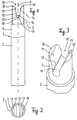
Bei der in den Figuren 4 bis 6 dargestellten Ausführungsformen sind in den Zapfen
30 eines Dentalprothesen-Rohlings 20 von der freien Stirnseite her zwei quer
zueinander liegende Schlitze 40, 60 eingeschnitten, die sich in der Achse 50 des
Rohlings 30 kreuzen. Dadurch entstehen jeweils zwei fluchtende Schlitzabschnitte
46, 48 beziehungsweise zwei fluchtende Schlitzabschnitte 66, 68. Jeder der
Schlitzabschnitte 46, 48 und 66, 68 weist an seinen Flanken gegenüberliegende, zur
Längsachse des jeweiligen Schlitzes 40 beziehungsweise 60 symmetrisch liegende
und zur Achse 50 parallele und plane Referenzflächen nach Art der
Referenzflächen 12, 14 auf, von denen in Fig. 6 die Referenzfläche 42 des
Schlitzabschnittes 46 und die Referenzfläche 49 des Schlitzabschnittes 48 sowie
die Referenzfläche 62 des Schlitzabschnittes 68 und die Referenzfläche 64 des
Schlitzabschnittes 66 zu erkennen sind. Gemäß Fig. 4 fluchten die Referenzflächen
42, 49 auf gleichliegenden Flanken der Schlitzabschnitte 46, 48 und die
Referenzflächen 44, 51 auf den gegenüberliegenden Flanken der gleichen
Schlitzabschnitte. Zum Eingriff in den Kreuzschlitz 40, 60 ist im Futter der
Haltevorrichtung selbstverständlich ein entsprechendes Stegkreuz vorgesehen.In the embodiments shown in Figures 4 to 6 are in the
Da der Mantel des Zapfens 30 zylindrisch ist, ergeben sich aufgrund der nach
außen gebogenen Einführflächen 41, 43 jeweils vier separate Pfosten 45, 47, 65,
67, die nach außen spitz zulaufen. Since the jacket of the
Die in den Figuren 7 bis 10 dargestellte Ausführungsform der Erfindung kommt
vor allem dann in Betracht, wenn das Material des Korpus 2 eine geringere Härte
hat dasjenige des Zapfens 3. In diesem Fall wird der Korpus 2 auf einen mit dem
Zapfen 73 versehenen Halter 80 stirnseitig aufgeklebt oder aufgeschweißt. Dazu
weist der Halter 80 eine stirnseitige kreisrunde Pfanne 75 mit außen umlaufendem
erhabenen Rand 77 um den Boden 79 auf, in welche der Korpus 2 eingesetzt
werden kann. Die vom Rand umschlossene lichte Weite ist nur wenig größer als
der Außendurchmesser des einzubringenden, hier zylindrischen Korpus. Der
Zapfen 73 entspricht in allen Einzelheiten dem Zapfen 3, ist also insbesondere mit
den dort beschriebenen Referenzflächen versehen. In Figur 9 ist eine dieser
Referenzflächen bei 72 zu erkennen.The embodiment of the invention shown in FIGS. 7 to 10 comes
especially when the material of the
Der Halter 82 nach Figur 10 unterscheidet sich vom Halter 80 lediglich darin, daß
der Rand in vier in Umfangsrichtung gleich beabstandete Randsegmente 83, 84, 86,
88 aufgeteilt ist, so daß sie mit dem Boden 89 einen quadratischen Bereich
umschließen, in welchen ein Korpus mit entsprechendem quadratischem
Querschnitt auf den Boden 89 zwischen die Randsegmente 83, 84, 86, 88
eingesetzt und dort verklebt werden kann.The
Claims (15)
Applications Claiming Priority (2)
| Application Number | Priority Date | Filing Date | Title |
|---|---|---|---|
| DE19932877 | 1999-07-16 | ||
| DE19932877A DE19932877B4 (en) | 1999-07-16 | 1999-07-16 | Dental prosthetic blank |
Publications (2)
| Publication Number | Publication Date |
|---|---|
| EP1068839A2 true EP1068839A2 (en) | 2001-01-17 |
| EP1068839A3 EP1068839A3 (en) | 2002-12-18 |
Family
ID=7914733
Family Applications (1)
| Application Number | Title | Priority Date | Filing Date |
|---|---|---|---|
| EP00115104A Withdrawn EP1068839A3 (en) | 1999-07-16 | 2000-07-12 | Moulded blank for dental prosthesis |
Country Status (4)
| Country | Link |
|---|---|
| US (1) | US6660400B1 (en) |
| EP (1) | EP1068839A3 (en) |
| JP (1) | JP2001046402A (en) |
| DE (1) | DE19932877B4 (en) |
Cited By (6)
| Publication number | Priority date | Publication date | Assignee | Title |
|---|---|---|---|---|
| EP2286759A2 (en) | 2009-08-20 | 2011-02-23 | Ivoclar Vivadent AG | Holder for CAD/CAM Blanks |
| WO2011029615A1 (en) * | 2009-09-11 | 2011-03-17 | Enta Holding B.V. | Tooth block for making dental prostheses, comprising a holder that is attached thereto |
| EP2246008A3 (en) * | 2009-05-02 | 2011-06-29 | White Peaks Dental Systems GmbH & Co. KG | Method for manufacturing artificial dental prostheses |
| WO2016079282A1 (en) * | 2014-11-21 | 2016-05-26 | Merz Dental Gmbh | Method for positioning a semifinished product, method for producing a semifinished product for reproducible positioning, and suitable semifinished product and corresponding use thereof |
| EP3047818A1 (en) * | 2015-01-21 | 2016-07-27 | STEGER, Heinrich | Holding device for a dental workpiece |
| RU2769884C1 (en) * | 2018-12-25 | 2022-04-07 | Токуяма Дентал Корпорейшн | Connecting structure for processing |
Families Citing this family (21)
| Publication number | Priority date | Publication date | Assignee | Title |
|---|---|---|---|---|
| SE522958C2 (en) | 2000-12-29 | 2004-03-16 | Nobel Biocare Ab | Procedure, arrangement (device) and programs at or for prosthetic installation |
| SE520765C2 (en) * | 2001-12-28 | 2003-08-19 | Nobel Biocare Ab | Device and arrangement for inserting holes for bone implants by means of template, preferably jawbones |
| US7534213B2 (en) * | 2002-09-09 | 2009-05-19 | Kneebourne Therapeutic, Llc | Knee extension treatment apparatus |
| SE526665C2 (en) * | 2002-12-30 | 2005-10-25 | Nobel Biocare Ab | Device for dental screw-in arrangement |
| SE526666C2 (en) * | 2002-12-30 | 2005-10-25 | Nobel Biocare Ab | Device and arrangement for fixture installation |
| DE10322762B4 (en) * | 2003-05-19 | 2013-12-05 | Sirona Dental Systems Gmbh | Holder for a blank and method for measuring the position and orientation of the holder |
| DE102004020369A1 (en) * | 2004-04-23 | 2005-11-17 | Sirona Dental Systems Gmbh | Method for producing a dental fitting |
| SE527503C2 (en) * | 2004-08-05 | 2006-03-21 | Nobel Biocare Ab | Device and method for facilitating application to correct position of tooth or tooth residue template |
| US20060172263A1 (en) * | 2005-02-01 | 2006-08-03 | D4D Technologies, Lp | Mill blank |
| US8540510B2 (en) | 2006-05-04 | 2013-09-24 | Nobel Biocare Services Ag | Device for securing a dental implant in bone tissue, a method for making a surgical template and a method of securing a dental implant in bone tissue |
| EP2099381B1 (en) * | 2006-12-28 | 2017-11-15 | Russell A. Giordano | Multicolor dental blank |
| US10206757B2 (en) | 2007-01-10 | 2019-02-19 | Nobel Biocare Services Ag | Method and system for dental planning and production |
| US8551622B2 (en) * | 2007-07-20 | 2013-10-08 | Ivoclar Vivadent Ag | Addressable matrices/cluster blanks for dental CAD/CAM systems and optimization thereof |
| US8568897B2 (en) * | 2007-07-20 | 2013-10-29 | Ivoclar Vivadent Ag | Addressable matrices/cluster blanks for dental CAD/CAM systems and optimization thereof |
| DE102007043837B4 (en) * | 2007-09-14 | 2014-02-13 | Ivoclar Vivadent Ag | blank arrangement |
| US8443502B2 (en) * | 2007-09-14 | 2013-05-21 | Ivoclar Vivadent Ag | Blank arrangement |
| EP2254068B1 (en) | 2009-05-18 | 2020-08-19 | Nobel Biocare Services AG | Method and system providing improved data matching for virtual planning |
| JP6253597B2 (en) * | 2012-02-29 | 2017-12-27 | イフォクレール ヴィヴァデント アクチェンゲゼルシャフトIvoclar Vivadent AG | Blank for making dental prosthesis |
| DE102012020519A1 (en) * | 2012-10-19 | 2014-04-24 | Eve Ernst Vetter Gmbh | Device for holding denture part i.e. tooth crown, has holder mechanism comprising expandable element in upper area, where holder mechanism comprises actuation part actuated for expanding expandable element |
| USD736389S1 (en) * | 2013-05-14 | 2015-08-11 | Ivoclar Vivadent Ag | Milling blank |
| US10010386B2 (en) | 2015-03-24 | 2018-07-03 | Ivoclar Vivadent Ag | Dental blank holder |
Citations (1)
| Publication number | Priority date | Publication date | Assignee | Title |
|---|---|---|---|---|
| EP0759728A1 (en) | 1994-05-05 | 1997-03-05 | Joseph Hintersehr | Method and device for manufacturing a dental prosthesis |
Family Cites Families (8)
| Publication number | Priority date | Publication date | Assignee | Title |
|---|---|---|---|---|
| DE3312908C2 (en) * | 1982-06-16 | 1986-11-20 | Gäßler GmbH & Co KG, 7900 Ulm | Arrangement for the releasable fastening of a dental prosthesis and method for its production |
| CH665551A5 (en) * | 1984-03-06 | 1988-05-31 | Werner Hans Dr Med De Moermann | BLANK FOR THE MANUFACTURE OF DENTAL TECHNOLOGY MOLDED PARTS. |
| ES2080206T3 (en) * | 1990-10-10 | 1996-02-01 | Mikrona Technologie Ag | RAW PIECE FOR THE MANUFACTURE OF A MACHINED PIECE OF DENTAL TECHNIQUE AND CLAMPING DEVICE FOR THE SAME. |
| US5362237A (en) * | 1991-08-02 | 1994-11-08 | Wellesley Research Associates, Inc. | Dental post construction |
| ATE281126T1 (en) * | 1996-05-17 | 2004-11-15 | Brandestini Marco | PROCESS FOR PRODUCING DENTAL RECONSTRUCTIONS AND BLANK FOR CARRYING OUT THE PROCESS |
| DE19733161C2 (en) * | 1997-07-31 | 2000-09-07 | Megadenta Gmbh Dentalprodukte | Holder and device for attaching a molded body |
| WO1999029255A1 (en) * | 1997-12-10 | 1999-06-17 | Diro, Inc. | Dental implant system and method |
| US6482284B1 (en) * | 2000-08-31 | 2002-11-19 | 3M Innovative Properties Company | Method of making a dental mill blank and support stub assembly |
-
1999
- 1999-07-16 DE DE19932877A patent/DE19932877B4/en not_active Revoked
-
2000
- 2000-07-12 EP EP00115104A patent/EP1068839A3/en not_active Withdrawn
- 2000-07-14 JP JP2000214330A patent/JP2001046402A/en active Pending
- 2000-07-17 US US09/618,146 patent/US6660400B1/en not_active Expired - Fee Related
Patent Citations (1)
| Publication number | Priority date | Publication date | Assignee | Title |
|---|---|---|---|---|
| EP0759728A1 (en) | 1994-05-05 | 1997-03-05 | Joseph Hintersehr | Method and device for manufacturing a dental prosthesis |
Cited By (8)
| Publication number | Priority date | Publication date | Assignee | Title |
|---|---|---|---|---|
| EP2246008A3 (en) * | 2009-05-02 | 2011-06-29 | White Peaks Dental Systems GmbH & Co. KG | Method for manufacturing artificial dental prostheses |
| EP2286759A2 (en) | 2009-08-20 | 2011-02-23 | Ivoclar Vivadent AG | Holder for CAD/CAM Blanks |
| WO2011029615A1 (en) * | 2009-09-11 | 2011-03-17 | Enta Holding B.V. | Tooth block for making dental prostheses, comprising a holder that is attached thereto |
| WO2016079282A1 (en) * | 2014-11-21 | 2016-05-26 | Merz Dental Gmbh | Method for positioning a semifinished product, method for producing a semifinished product for reproducible positioning, and suitable semifinished product and corresponding use thereof |
| US10993790B2 (en) | 2014-11-21 | 2021-05-04 | Merz Dental Gmbh | Method for positioning a semifinished product, method for producing a semifinished product for reproducible positioning, and suitable semifinished product and corresponding use thereof |
| EP3047818A1 (en) * | 2015-01-21 | 2016-07-27 | STEGER, Heinrich | Holding device for a dental workpiece |
| US10213841B2 (en) | 2015-01-21 | 2019-02-26 | Heinrich Steger | Holding apparatus for a dental workpiece |
| RU2769884C1 (en) * | 2018-12-25 | 2022-04-07 | Токуяма Дентал Корпорейшн | Connecting structure for processing |
Also Published As
| Publication number | Publication date |
|---|---|
| US6660400B1 (en) | 2003-12-09 |
| JP2001046402A (en) | 2001-02-20 |
| DE19932877B4 (en) | 2006-10-26 |
| DE19932877A1 (en) | 2001-01-25 |
| EP1068839A3 (en) | 2002-12-18 |
Similar Documents
| Publication | Publication Date | Title |
|---|---|---|
| EP1068839A2 (en) | Moulded blank for dental prosthesis | |
| EP1616645B1 (en) | Indexable cutting insert for turning | |
| DE4444241C2 (en) | Jig | |
| EP3047818B1 (en) | Holding device for a dental workpiece | |
| EP0255042A1 (en) | Tool holder for a machine tool, especially an electric discharge machine | |
| EP1136158A1 (en) | Cutting insert holder for turning tools and grooving insert therefor | |
| DE2744410A1 (en) | 4-JAW CHUCK FOR ONE WORKPIECE | |
| EP3582917A2 (en) | Hole saw | |
| EP3463724A1 (en) | Cutting insert and tool for machining | |
| EP3909477A1 (en) | Curtain hook | |
| EP0523404B1 (en) | Tool for milling and drilling with two cutting edges | |
| DE69923362T2 (en) | Tool for machining | |
| DE4339271C1 (en) | Clamping device for releasable holding of workpieces | |
| EP0144073B1 (en) | Cutting tool | |
| EP1049555B1 (en) | Collet chuck for holding bars in lathes | |
| EP3463731B1 (en) | Cutting insert for a milling tool and milling tool | |
| DE3530745A1 (en) | KNIFE HEAD | |
| DE2112092A1 (en) | Tool holder | |
| EP3741483A1 (en) | Cutting insert, holder and cutting device | |
| DE102018107453B4 (en) | hob milling | |
| DE3511580C2 (en) | ||
| DE2628624A1 (en) | Cylindrical milling cutter with separate inserts - has blades in recesses extending from free end face and open towards periphery | |
| DE2064451A1 (en) | Cutting tool | |
| DE19500946C1 (en) | Angle-adjustable workpiece seat | |
| DE102021122424A1 (en) | Machining tool, cutting insert holder and cutting insert |
Legal Events
| Date | Code | Title | Description |
|---|---|---|---|
| PUAI | Public reference made under article 153(3) epc to a published international application that has entered the european phase |
Free format text: ORIGINAL CODE: 0009012 |
|
| AK | Designated contracting states |
Kind code of ref document: A2 Designated state(s): AT BE CH CY DE DK ES FI FR GB GR IE IT LI LU MC NL PT SE |
|
| AX | Request for extension of the european patent |
Free format text: AL;LT;LV;MK;RO;SI |
|
| PUAL | Search report despatched |
Free format text: ORIGINAL CODE: 0009013 |
|
| AK | Designated contracting states |
Kind code of ref document: A3 Designated state(s): AT BE CH CY DE DK ES FI FR GB GR IE IT LI LU MC NL PT SE |
|
| AX | Request for extension of the european patent |
Free format text: AL;LT;LV;MK;RO;SI |
|
| 17P | Request for examination filed |
Effective date: 20021219 |
|
| AKX | Designation fees paid |
Designated state(s): AT CH DE FR LI SE |
|
| STAA | Information on the status of an ep patent application or granted ep patent |
Free format text: STATUS: THE APPLICATION IS DEEMED TO BE WITHDRAWN |
|
| 18D | Application deemed to be withdrawn |
Effective date: 20060120 |