EP1069449A2 - Illumination system for a deep ultraviolet microscope - Google Patents
Illumination system for a deep ultraviolet microscope Download PDFInfo
- Publication number
- EP1069449A2 EP1069449A2 EP00111442A EP00111442A EP1069449A2 EP 1069449 A2 EP1069449 A2 EP 1069449A2 EP 00111442 A EP00111442 A EP 00111442A EP 00111442 A EP00111442 A EP 00111442A EP 1069449 A2 EP1069449 A2 EP 1069449A2
- Authority
- EP
- European Patent Office
- Prior art keywords
- duv
- reflection
- beam path
- lighting device
- vis
- Prior art date
- Legal status (The legal status is an assumption and is not a legal conclusion. Google has not performed a legal analysis and makes no representation as to the accuracy of the status listed.)
- Granted
Links
- 238000005286 illumination Methods 0.000 title claims description 31
- 230000003595 spectral effect Effects 0.000 claims description 12
- 230000003287 optical effect Effects 0.000 claims description 6
- 229910004298 SiO 2 Inorganic materials 0.000 claims description 3
- 229910018072 Al 2 O 3 Inorganic materials 0.000 claims description 2
- 239000000758 substrate Substances 0.000 claims 1
- 239000012780 transparent material Substances 0.000 claims 1
- 230000001419 dependent effect Effects 0.000 description 7
- 230000010287 polarization Effects 0.000 description 7
- 230000005540 biological transmission Effects 0.000 description 5
- 230000000694 effects Effects 0.000 description 3
- 239000011521 glass Substances 0.000 description 3
- 239000000463 material Substances 0.000 description 3
- 238000001228 spectrum Methods 0.000 description 2
- 238000007740 vapor deposition Methods 0.000 description 2
- VYPSYNLAJGMNEJ-UHFFFAOYSA-N Silicium dioxide Chemical compound O=[Si]=O VYPSYNLAJGMNEJ-UHFFFAOYSA-N 0.000 description 1
- 239000012876 carrier material Substances 0.000 description 1
- 230000003760 hair shine Effects 0.000 description 1
- 229910052736 halogen Inorganic materials 0.000 description 1
- 150000002367 halogens Chemical class 0.000 description 1
- 238000003384 imaging method Methods 0.000 description 1
- 238000007689 inspection Methods 0.000 description 1
- 239000002184 metal Substances 0.000 description 1
- 238000000034 method Methods 0.000 description 1
- 238000001000 micrograph Methods 0.000 description 1
- 210000001747 pupil Anatomy 0.000 description 1
Images


Classifications
-
- G—PHYSICS
- G02—OPTICS
- G02B—OPTICAL ELEMENTS, SYSTEMS OR APPARATUS
- G02B21/00—Microscopes
- G02B21/16—Microscopes adapted for ultraviolet illumination ; Fluorescence microscopes
Definitions
- the invention relates to an illumination device for a DUV microscope the features of the preamble of independent claim 1.
- the DUV wavelength band is characterized by the spectral peak position and the half-width of its peak.
- Both transmission narrow-band filter systems and reflection filter systems are known for generating such a DUV wavelength band. These filter systems are inserted into the illumination beam path and filter a desired DUV wavelength band as useful light from the light spectrum of a light source.
- the microscope image is made visible with a DUV-sensitive TV camera.
- Transmission narrow-band filter systems in the DUV deliver very narrow peaks, the maximum transmission and therefore the peak value of the peak is included only about 20 percent of the light intensity in front of the transmission narrow-band filter system.
- Such weak intensities require particularly sensitive ones and therefore technologically complex and very expensive cameras.
- the significant disadvantage of these cameras e.g. with so-called "frame transfer CCD imagers" is, however, that they have very long exposure and image readout times have, so that a "life" observation of the object is impossible. This is particularly annoying when the stage moves with the object on it must become.
- the invention is based on the consideration that the large half-widths essentially through polarization effects on the reflection filter systems caused. These are significantly lower for smaller reflection angles.
- a reflection filter system is therefore used in a DUV lighting device according to the invention with small reflection angles and spectrally adjusted Reflection filters used.
- a lighting device for a DUV microscope has a light source from which an illumination beam path emanates.
- Illumination beam paths are a collector and a reflection filter system arranged to generate a desired DUV wavelength band.
- the Reflection filter system consists of four reflection filters on which the illuminating beam path is reflected at the same angle of reflection a.
- the illuminating beam path runs in front of and behind the reflection filter system coaxial. According to the angle of reflection a at the individual reflection filters between ⁇ ⁇ 30 °.
- the reflection filter system provides a very narrow DUV wavelength band ⁇ DUV + ⁇ with a half width of max. 20 nm. It has a peak with a peak value S of over 90% of the incident light intensity. Depending on the reflection filter used, a peak peak value S of over 98% of the incident light intensity can be achieved with a reflection filter system with small angles of incidence.
- reflection filters specially matched to the desired DUV wavelength band ⁇ DUV + ⁇ are used in the reflection filter system of the lighting device according to the invention.
- the reflection filter system can the polarization effects on the reflection filters reduced and narrow half-widths can be achieved. For half-widths in the order of magnitude achieved, it is possible to correct appropriately Calculate DUV microscope objectives. At the same time has a DUV microscope sufficient with a lighting device according to the invention high intensities in the illumination beam path in order to focus on complex special DUV-sensitive cameras, such as the frame transfer CCD cameras mentioned, with slow image build-up.
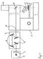
- An illuminating beam path 6 emanates from the light source 5, passes through a collector 7 and a reflecting filter system 9 constructed from four reflecting filters 8. From there, the illuminating beam path 6 passes through an optical system (not shown), is deflected at a beam splitter 10 and through the objective 2 onto the Object 4 focused.
- the imaging beam path emanating from the object 4 passes through the objective 2 and the beam splitter 10 to the TV camera 11.
- the reflection filters 8 in the reflection filter system 9 are like this arranged that the illumination beam path 6 on all reflection filters 8th with the same small angle of incidence ⁇ .
- An angle of 30 ° is shown here. Smaller angles are possible according to the invention.
- reflection filter filter systems with angles of incidence ⁇ ⁇ 15 ° due to the narrow geometry can only be realized with difficulty.
- the desired DUV wavelength range adapted reflection filter 8 from vapor deposition layers are applied to black glass.
- the desired DUV portion of the lamp light is reflected.
- the parts passing through the vapor deposition layers of the lamp light, i.e. the remaining DUV portion as well as the UV and VIS components are absorbed in the black glass. In this way it is created Illumination with only the desired DUV wavelength range.
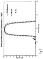
- the polarization components with vertical (“S-Pol”) and parallel (“P-Pol”) polarization directions are shown. These two curves are very close together because the polarization effect is only very small due to the small angle of incidence. Therefore, the summation curve "pole-sum" from the two polarization directions also has only a very small half-width ⁇ with a value of approximately 20 nm. This means that the DUV wavelength band ⁇ DUV generated with a reflection filter system with a small angle of incidence is sufficiently narrow to be able to correct the DUV optics of the microscope.
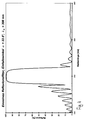
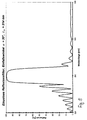
- the reflection filters have a layer structure as shown in Table 1. Only the thicknesses of the layers are corrected in accordance with the desired angle of incidence ci by a reference wavelength ⁇ 0 , which is included in the calculation of the layer thicknesses. The associated reference wavelengths ⁇ 0 are given in the figures. By adapting the layer thicknesses, the reflection filters have the same qualitative reflection behavior for different angles of incidence. 6 shows the reference wavelength ⁇ 0 as a function of the angle of incidence ⁇ . It can be seen that for changes to larger angles of incidence, the reference wavelength ⁇ 0 must be corrected significantly more.
- the layer system from Table 1 is again suitable, for example. However, it is also possible to design other layer systems, for example using SiO 2 and AlO 3 . It is important to use materials with the smallest possible differences in their refractive indices. With the layer system from Table 1, at least for a DUV wavelength between 180 and 300 nm, a reflection filter system that is suitable for a narrow DUV wavelength band can be specified.
- Fig. 8 shows a switchable lighting device for optional VIS or DUV lighting, which is equipped with two separate light sources for two wavelength ranges.
- the structure corresponds in principle to FIG. 1.
- the same components have the same reference numerals.
- An additional VIS light source 12 for the visible spectral range has been added to the previously described lighting device from FIG. 1 with the DUV light source 5.
- This VIS light source 12 is, for example, an Hg incandescent lamp which only emits spectral components in the VIS wavelength range, but not in the UV and DUV wavelength ranges.
- the light from this VIS light source 12 passes through a collector 13 and is only coupled vertically into the illuminating beam path 6 when an additionally installed, pivotable mirror 14 is located in the illuminating beam path 6 in the position "b". Then the VIS light arrives at the object 4 on the following part of the illumination beam path 6.
- the swivel mirror 14 is brought into the position "a”. Then the light from the DUV light source 5 reaches the object 4 as in FIG. 1 .
- the structure described requires a second light source, but is through the swivel mirror 14 easy to implement.
- the structure also expands the possibilities of using the microscope considerably. This is how the DUV light source shines 5, e.g. an Hg arc lamp, also in the UV and VIS wavelength range from. However, it has only a small arc, the with weaker VIS lenses, the pupil cannot fill and therefore no lighting for these lenses. In addition, the DUV light source 5 not dimmable.
- the VIS light source e.g. a halogen light bulb, one sufficiently large filament for sufficient lighting also with weaker VIS lenses and is dimmable. You have UV or DUV portions Spectrum not on. Therefore, with the structure described, a DUV microscope be equipped with all the options for a VIS inspection.
- FIG. 9 shows the different positions of the images of a universal light source for the VIS and UV and DUV wavelength ranges in a DUV lighting device.
- the light from the light source 15 passes through a collector 16 and a reflection filter system 9, which is constructed from four reflection filters 8.
- the reflection filters 8 are evaporated on black glass.
- the different positions of the image 17 of the light source 15 for the DUV wavelength 248 nm, the so-called "i-line” 365 nm and the visible VIS wavelength range are shown schematically.
- the light source 15 would have to be different spectral lighting method in the direction of the illumination beam path 6 be moved.
- FIGS. 10-11 An alternative to this is shown in FIGS. 10-11 .
- a switchable lighting device for either VIS or DUV lighting is shown, which works with only one universal DUV-VIS light source.
- the DUV light source 5 is used, which is an Hg arc lamp, for example.
- An illuminating beam path 6 starts from the DUV light source 5, in which a collector 7 and a reflection filter system 9 with four reflection filters 8 are arranged.
- the four reflection filters 8 are individually identified here with 8a, 8b, 8c and 8d to differentiate their spatial position.
- the reflection filters 8a, 8b, 8c and 8d are vapor-deposited on a carrier material, ie quartz glass, which is transparent for all wavelength ranges.
- a light stopper 18 is inserted between the reflection filter 8a and the reflection filter 8d.
- This can be any opaque plate, e.g. made of metal. This stops the portion of the lamp light passing through the reflection filter 8a, so that only the reflected DUV wavelength band is used for illumination.
- the position 17 of the image of the light source 5 is indicated.
- the lenses 19 shift the position 17 of the VIS image of the light source to the position of the DUV image of the light source.
- the filter 20 can be a color filter or gray filter etc.
- a light stopper 18 is inserted between the reflection filter 8b and the reflection filter 8d in order to exclude any DUV component from the illumination during the VIS illumination.
- FIG. 12 shows a linear slide 21 with which the two switching stages from FIGS. 10 and 11 and one further switching stage can be implemented.
- the linear slide 21 shows three buttons 22, 23, 24 for different spectral lighting variants.
- the linear slide 21 is inserted vertically into the illumination beam path 6 in the reflection filter system 9, so that its upper half is always between the reflection filter 8b and the reflection filter 8c and its lower half is always between the reflection filter 8a and the reflection filter 8d.
- Only one of the buttons 22, 23, 24 is optionally inserted into the illumination beam path 6.
- the position 28 of the reflection filter system is represented by a dashed frame. In FIG. 12 , the button 23 is therefore currently inserted in the reflection filter system.
- the button 22 generates a DUV lighting, thus corresponds to FIG. 10 .
- a free opening 25 is arranged in its upper half to allow the DUV light to pass through.
- a light stopper 18 is arranged in its lower half.
- the button 23 generates a VIS illumination, which corresponds to FIG. 11 .
- a light stopper 18 is arranged in its upper half to stop the DUV light.
- a lens-filter combination 26 of lenses and at least one filter is inserted in its lower half, which are selected for the VIS range.
- the lenses correct the position of the image of the light source.
- the filters can be selected as required, eg color filters, gray filters, fluorescence filters etc.
- a further lighting with wavelengths outside of the DUV wavelength band can be set.
- a light stopper 18 is again arranged to stop the DUV light.
- any lens-filter combination 27 is inserted into its lower half, which is selected for example for the so-called "i-line" at 365 nm.
Abstract
Description
Die Erfindung betrifft eine Beleuchtungseinrichtung für ein DUV-Mikroskop mit
den Merkmalen des Oberbegriffs des unabhängigen Anspruchs 1.The invention relates to an illumination device for a DUV microscope
the features of the preamble of
Beleuchtungseinrichtungen für DUV-Mikroskope müssen ein schmales DUV-Wellenlängenband aus dem DUV-Wellenlängenbereich (DUV = deep ultraviolet, ca. 200 bis 300 nm) für die Beleuchtung bereitstellen, für welches die Mikroskop-Optik korrigiert ist. Das DUV-Wellenlängenband wird charakterisiert durch die spektrale Spitzenwertlage und die Halbwertsbreite seines Peaks. Zur Erzeugung eines solchen DUV-Wellenlängenbandes sind sowohl Transmissions-Schmalband-Filtersysteme als auch Refiexionsfilter-Systeme bekannt. Diese Filtersysteme werden in den Beleuchtungsstrahlengang eingefügt und filtern aus dem Lichtspektrum einer Lichtquelle ein gewünschtes DUV-Wellenlängenband als Nutzlicht aus. Das Mikroskopbild wird mit einer DUV-empfindlichen TV-Kamera sichtbar gemacht.Illumination devices for DUV microscopes must provide a narrow DUV wavelength band from the DUV wavelength range (DUV = d eep u ltra v iolet, approx. 200 to 300 nm) for the illumination, for which the microscope optics are corrected. The DUV wavelength band is characterized by the spectral peak position and the half-width of its peak. Both transmission narrow-band filter systems and reflection filter systems are known for generating such a DUV wavelength band. These filter systems are inserted into the illumination beam path and filter a desired DUV wavelength band as useful light from the light spectrum of a light source. The microscope image is made visible with a DUV-sensitive TV camera.
Transmissions-Schmalband-Filtersysteme im DUV liefern sehr schmale Peaks, dafür liegt die maximale Transmission und damit der Spitzenwert des Peaks bei nur etwa 20 Prozent der Lichtintensität vor dem Transmissions-Schmalband-Filtersystem. Derart schwache Intensitäten erfordern jedoch besonders empfindliche und damit technologisch aufwendige und sehr teure Kameras. Der wesentliche Nachteil dieser Kameras (z.B. bei sogenannten "Frame-Transfer-CCD-Imagern") ist jedoch, daß sie sehr lange Belichtungs- und Bildauslesezeiten haben, so daß eine "life"-Beobachtung des Objektes unmöglich ist. Dies ist insbesondere störend, wenn der Objekttisch mit dem aufliegenden Objekt verfahren werden muß.Transmission narrow-band filter systems in the DUV deliver very narrow peaks, the maximum transmission and therefore the peak value of the peak is included only about 20 percent of the light intensity in front of the transmission narrow-band filter system. Such weak intensities, however, require particularly sensitive ones and therefore technologically complex and very expensive cameras. The significant disadvantage of these cameras (e.g. with so-called "frame transfer CCD imagers") is, however, that they have very long exposure and image readout times have, so that a "life" observation of the object is impossible. This is particularly annoying when the stage moves with the object on it must become.
Bekannte Reflexionsfilter-Systeme bestehen aus mehreren Reflexionsfiltern, an denen das Licht der Lichtquelle jeweils unter einem Einfallswinkel α = 450 auftrifft und reflektiert wird. Bei diesen bekannten Reflexionsfilter-Systemen liegt der Spitzenwert des Peaks deutlich über 90 Prozent. Ihr Nachteil besteht jedoch darin, daß ihre Halbwertsbreite ungefähr 30 bis 50 nm beträgt. Es ist jedoch extrem schwierig und aufwendig, Mikroobjektive mit kurzer Brennweite, d.h. hoher Vergrößerung, im DUV-Wellenlängenbereich für ein so breites DUV-Wellenlängenband zu korrigieren.Known reflection filter systems consist of several reflection filters which the light from the light source strikes at an angle of incidence α = 450 and is reflected. These known reflection filter systems lie the peak value of the peak is well over 90 percent. However, there is a disadvantage in that their full width at half maximum is about 30 to 50 nm. However, it is extremely difficult and expensive, micro lenses with a short focal length, i.e. high magnification, in the DUV wavelength range for such a wide DUV wavelength band to correct.
Es ist daher Aufgabe der vorliegenden Erfindung, eine Beleuchtungseinrichtung für ein DUV-Mikroskop anzugeben, welche ein DUV-Wellenlängenband mit maximaler Transmission und geringer Halbwertsbreite bereitstellt.It is therefore an object of the present invention to provide a lighting device specify for a DUV microscope which a DUV wavelength band with provides maximum transmission and narrow half-width.
Diese Aufgabe wird gelöst durch eine Beleuchtungseinrichtung, welche die
Merkmale des unabhängigen Anspruchs 1 aufweist. Vorteilhafte Ausführungen
der Beleuchtungseinrichtung sind in den Unteransprüchen angegeben.This object is achieved by a lighting device, which the
Features of
Die Erfindung geht von der Überlegung aus, daß die großen Halbwertsbreiten im wesentlichen durch Polarisationseffekte an den Reflexionsfilter-Systemen verursacht werden. Diese sind für kleinere Reflexionswinkel deutlich geringer. Daher wird in einer erfindungsgemäßen DUV-Beleuchtungseinrichtung ein Reflexionsfilter-System mit kleinen Reflexionswinkeln und spektral angepaßten Reflexionsfiltern verwendet.The invention is based on the consideration that the large half-widths essentially through polarization effects on the reflection filter systems caused. These are significantly lower for smaller reflection angles. A reflection filter system is therefore used in a DUV lighting device according to the invention with small reflection angles and spectrally adjusted Reflection filters used.
Eine erfindungsgemäße Beleuchtungseinrichtung für ein DUV-Mikroskop weist eine Lichtquelle auf, von der ein Beleuchtungsstrahlengang ausgeht. In dem Beleuchtungsstrahlengang sind ein Kollektor und ein Reflexionsfilter-System zur Erzeugung eines gewünschten DUV-Wellenlängenbandes angeordnet. Das Reflexionsfilter-System besteht aus vier Reflexionsfiltern, an denen der Beleuchtungsstrahlengang jeweils im gleichen Reflexionswinkel a reflektiert wird. A lighting device according to the invention for a DUV microscope has a light source from which an illumination beam path emanates. By doing Illumination beam paths are a collector and a reflection filter system arranged to generate a desired DUV wavelength band. The Reflection filter system consists of four reflection filters on which the illuminating beam path is reflected at the same angle of reflection a.
Dabei verläuft der Beleuchtungsstrahlengang vor und hinter dem Reflexionsfilter-System koaxial. Erfindungsgemäß beträgt der Reflexionswinkel a an den einzelnen Reflexionsfiltern zwischen α ≤ 30°.The illuminating beam path runs in front of and behind the reflection filter system coaxial. According to the angle of reflection a at the individual reflection filters between α ≤ 30 °.
Dabei liefert das Reflexionsfilter-System ein sehr schmales DUV-Wellenlängenband λDUV + Δλ mit einer Halbwertsbreite von max. 20 nm. Es weist einen Peak mit einem Spitzenwert S von über 90% der eingestrahlten Lichtintensität auf. Je nach verwendeten Reflexionsfiltern kann durch ein Reflexionsfilter-System mit kleinen Einfallswinkeln ein Peak-Spitzenwert S von über 98% der eingestrahlten Lichtintensität erzielt werden. Dazu werden in das Reflexionsfilter-System der erfindungsgemäßen Beleuchtungseinrichtung speziell auf das gewünschte DUV-Wellenlängenband λDUV + Δλ abgestimmte Reflexionsfilter eingesetzt.The reflection filter system provides a very narrow DUV wavelength band λ DUV + Δλ with a half width of max. 20 nm. It has a peak with a peak value S of over 90% of the incident light intensity. Depending on the reflection filter used, a peak peak value S of over 98% of the incident light intensity can be achieved with a reflection filter system with small angles of incidence. For this purpose, reflection filters specially matched to the desired DUV wavelength band λ DUV + Δλ are used in the reflection filter system of the lighting device according to the invention.
Durch Übergang zu den erfindungsgemäß kleinen Reflexionswinkeln α ≤ 30° in
dem Reflexionsfilter-System können die Polarisationseffekte an den Reflexionsfiltern
verringert und derart schmale Halbwertsbreiten erzielt werden. Für Halbwertsbreiten
in der erzielten Größenordnung ist es möglich, passend korrigierte
DUV-Mikroskop-Objektive zu berechnen. Gleichzeitig besitzt ein DUV-Mikroskop
mit einer erfindungsgemäßen Beleuchtungseinrichtung ausreichend
hohe Intensitäten im Beleuchtungsstrahlengang, um auf aufwendige spezielle
DUV-empfindliche Kameras, wie z.B. die genannten Frame-Transfer-CCD-Kameras,
mit langsamem Bildaufbau zu verzichten. By transitioning to the
Die Erfindung wird anhand von Ausführungsbeispielen mithilfe der schematischen Zeichnung näher erläutert. Es zeigen:
- Fig. 1:
- eine erfindungsgemäße DUV-Beleuchtungseinrichtung für ein Mikroskop;
- Fig. 2:
- wellenlängenabhängige Reflexion an einem Reflexionsfilter-System mit einem kleinen Einfallswinkel α = 22,5, aufgeteilt in Polarisationsanteile;
- Fig. 3:
- wellenlängenabhängige Reflexion an einem einzelnen Reflexionsfilter für einen Einfallswinkel α = 15° und eine Bezugswellenlänge λ0= 303,5 nm;
- Fig. 4:
- wellenlängenabhängige Reflexion an einem einzelnen Reflexionsfilter für einen Einfallswinkel α = 22,5° und eine Bezugswellenlänge λ0= 308 nm;
- Fig. 5:
- wellenlängenabhängige Reflexion an einem einzelnen Reflexionsfilter für einen Einfallswinkel α = 30° und eine Bezugswellenlänge λ0= 314 nm;
- Fig. 6:
- Bezugswellenlänge λ0 in Abhängigkeit von dem Einfallswinkel α;
- Fig. 7:
- wellenlängenabhängige Reflexion für drei auf verschiedene DUV-Wellenlängen angepaßte Reflexionsfilter-Systeme, jeweils mit einem Einfallswinkel α = 22,5,
- Fig. 8:
- umschaltbare Beleuchtungseinrichtung für wahlweise VIS- oder DUV-Beleuchtung mit zwei separaten DUV- und VIS-Lichtquellen;
- Fig. 9:
- Lage der Lampenbilder für VIS, UV, DUV in einer DUV- Beleuchtungseinrichtung mit einer universellen DUV-VIS-Lichtquelle;
- Fig.10:
- umschaltbare Beleuchtungseinrichtung für wahlweise VIS- oder DUV-Beleuchtung mit einer universellen DUV-VIS-Lichtquelle in der Schaltstufe "DUV-Beleuchtung";
- Fig.11:
- umschaltbare Beleuchtungseinrichtung aus Fig.10 für wahlweise VIS- oder DUV-Beleuchtung mit einer universellen DUV-VIS-Lichtquelle in des Schaltstufe "VIS-Beleuchtung";
- Fig. 12:
- Linearschieber für die umschaltbare Beleuchtungseinrichtung aus Fig. 10 und Fig. 11 mit drei Schaltflächen;
- Fig. 1:
- a DUV illumination device according to the invention for a microscope;
- Fig. 2:
- wavelength-dependent reflection on a reflection filter system with a small angle of incidence α = 22.5, divided into polarization components;
- Fig. 3:
- wavelength-dependent reflection on a single reflection filter for an angle of incidence α = 15 ° and a reference wavelength λ 0 = 303.5 nm;
- Fig. 4:
- wavelength-dependent reflection on a single reflection filter for an angle of incidence α = 22.5 ° and a reference wavelength λ 0 = 308 nm;
- Fig. 5:
- wavelength-dependent reflection on a single reflection filter for an angle of incidence α = 30 ° and a reference wavelength λ 0 = 314 nm;
- Fig. 6:
- Reference wavelength λ 0 as a function of the angle of incidence α;
- Fig. 7:
- wavelength-dependent reflection for three reflection filter systems adapted to different DUV wavelengths, each with an angle of incidence α = 22.5,
- Fig. 8:
- switchable lighting device for optional VIS or DUV lighting with two separate DUV and VIS light sources;
- Fig. 9:
- Location of lamp images for VIS, UV, DUV in a DUV lighting device with a universal DUV-VIS light source;
- Fig. 10:
- switchable lighting device for optional VIS or DUV lighting with a universal DUV-VIS light source in the switching stage "DUV lighting";
- Fig. 11:
- switchable lighting device from Fig. 10 for optional VIS or DUV lighting with a universal DUV-VIS light source in the "VIS lighting" switching stage;
- Fig. 12:
- Linear slide for the switchable lighting device from FIGS. 10 and 11 with three buttons;
Fig. 1 zeigt ein Mikroskop 1 mit Objektiven 2 und einem auf einem Objekttisch
3 liegenden Objekt 4. Als DUV-Lichtquelle 5 wird beispielsweise eine Hg-Drucklampe
mit Spektralanteilen im VIS- und UV- und DUV-Wellenlängenbereich
verwendet (Definition der Spektralbereiche: VIS = sichtbarer;
UV = ultravioletter; DUV deep UV). Von der Lichtquelle 5 geht ein Beleuchtungsstrahlengang
6 aus, passiert einen Kollektor 7 und ein aus vier Reflexionsfiltern
8 aufgebautes Reflexionsfilter-System 9. Von dort durchläuft der Beleuchtungsstrahlengang
6 eine nicht dargestellte Beleuchtungsoptik, wird an
einem Strahlteiler 10 umgelenkt und durch das Objektiv 2 auf das Objekt 4 fokussiert.
Der von dem Objekt 4 ausgehende Abbildungsstrahlengang geht
durch das Objektiv 2 und den Strahlteiler 10 zur TV-Kamera 11. 1 shows a
Erfindungsgemäß sind die Reflexionsfilter 8 in dem Reflexionsfilter-System 9 so
angeordnet, daß der Beleuchtungsstrahlengang 6 an allen Reflexionsfiltern 8
mit demselben kleinen Einfallswinkel α auftrifft. Hier ist ein Winkel von 30° dargestellt.
Kleinere Winkel sind erfindungsgemäß möglich. Jedoch können Reflexionsfilters-Filterssysteme
mit Einfallswinkeln α < 15° wegen der engen Geometrie
nur noch schwierig realisiert werden.According to the invention, the reflection filters 8 in the
Im dargestellten Beipiel bestehen die auf den gewünschten DUV-Wellenlängenbereich
angepaßten Reflexionsfilter 8 aus Aufdampfschichten, die
auf Schwarzglas aufgebracht sind. Der gewünschte DUV-Anteil des Lampenlichts
wird reflektiert. Die durch die Aufdampfschichten hindurchgehenden Anteile
des Lampenlichts, also der verbleibende DUV-Anteil sowie die UV- und
VIS-Anteile, werden in dem Schwarzglas absorbiert. Auf diese Weise entsteht
eine Beleuchtung mit ausschließlich dem gewünschten DUV-Wellenlängenbereich.In the example shown, they insist on the desired DUV wavelength range
adapted
Fig. 2 zeigt die Reflexion an einem Reflexionsfilter-System mit einem kleinen Einfallswinkel α = 22,5° in Abhängigkeit von der Wellenlänge. Dargestellt sind die durch Polarisation bei der Reflexion entstehenden Polarisationsanteile mit senkrechter ("S-Pol") und paraller ("P-Pol") Polarisationsrichtung. Diese beiden Kurven liegen sehr dicht beieinander, weil der Polarisationseffekt aufgrund des kleinen Einfallswinkels nur sehr klein ist. Daher weist die Summenkurve "Pol-Summe" aus den beiden Polarisationsrichtungen auch eine nur sehr geringe Halbwertsbreite Δλ mit einem Wert von ca. 20 nm auf. Damit ist das mit einem Reflexionsfilter-System mit kleinem Einfallswinkel erzeugte DUV-Wellenlängenband λDUV ausreichend schmal, um die DUV-Optik des Mikroskops darauf korrigieren zu können. Fig. 2 shows the reflection on a reflection filter system with a small angle of incidence α = 22.5 ° depending on the wavelength. The polarization components with vertical ("S-Pol") and parallel ("P-Pol") polarization directions are shown. These two curves are very close together because the polarization effect is only very small due to the small angle of incidence. Therefore, the summation curve "pole-sum" from the two polarization directions also has only a very small half-width Δλ with a value of approximately 20 nm. This means that the DUV wavelength band λ DUV generated with a reflection filter system with a small angle of incidence is sufficiently narrow to be able to correct the DUV optics of the microscope.
Die Fig. 3-5 zeigen die wellenlängenabhängige Reflexion an unterschiedlichen einzelnen Reflexionsfiltern, die für verschiedene Einfallswinkel α ausgelegt sind. Die Reflexionsfilter besitzen eine Schichtaufbau wie er in Tabelle 1 angegeben ist. Lediglich die Dicken der Schichten werden entsprechend dem gewünschten Einfallswinkel ci durch eine Bezugswellenlänge λ0 , die in die Berechnung der Schichtdicken eingeht, korrigiert. Die zugehörigen Bezugswellenlängen λ0 sind in den Figuren angegeben. Durch die Anpassung der Schichtdicken besitzen die Reflexionsfilter auch für verschiedene Einfallswinkel ein qualitativ gleiches Reflexionsverhalten. In Fig. 6 ist die Bezugswellenlänge λ0 in Abhängigkeit von dem Einfallswinkel α dargestellt. Man erkennt, daß für Änderungen zu größeren Einfallswinkeln die Bezugswellenlänge λ0 deutlich stärker nachkorrigiert werden muß. 3-5 show the wavelength-dependent reflection at different individual reflection filters, which are designed for different angles of incidence α. The reflection filters have a layer structure as shown in Table 1. Only the thicknesses of the layers are corrected in accordance with the desired angle of incidence ci by a reference wavelength λ 0 , which is included in the calculation of the layer thicknesses. The associated reference wavelengths λ 0 are given in the figures. By adapting the layer thicknesses, the reflection filters have the same qualitative reflection behavior for different angles of incidence. 6 shows the reference wavelength λ 0 as a function of the angle of incidence α. It can be seen that for changes to larger angles of incidence, the reference wavelength λ 0 must be corrected significantly more.
Fig. 7 zeigt die wellenlängenabhängige Reflexion für drei auf verschiedene DUV-Wellenlängen angepaßte Reflexionsfilter-Systeme, deren Reflexionsfilter jeweils für denselben Einfallswinkel α = 22,5 ausgelegt sind. Geeignet ist zum Beispiel wieder das Schichten-System aus Tabelle 1. Es ist aber auch möglich andere Schichten-Systeme, z.B. unter Verwendung von SiO2 und Al03 , zu konzipieren. Dabei ist es wichtig, Materialien mit möglichst kleine Differenzen ihrer Brechungsindices zu verwenden. Mit dem Schichten-System aus Tabelle 1 kann mindestens für einen DUV-Wellenlängen zwischen 180 und 300 nm ein jeweils für ein schmales DUV-Wellenlängenband passendes Reflexionsfilter-System angeben werden. 7 shows the wavelength-dependent reflection for three reflection filter systems adapted to different DUV wavelengths, the reflection filters of which are each designed for the same angle of incidence α = 22.5. The layer system from Table 1 is again suitable, for example. However, it is also possible to design other layer systems, for example using SiO 2 and AlO 3 . It is important to use materials with the smallest possible differences in their refractive indices. With the layer system from Table 1, at least for a DUV wavelength between 180 and 300 nm, a reflection filter system that is suitable for a narrow DUV wavelength band can be specified.
Nachfolgend sollen noch zwei Ausführungsbeipiele für eine auf verschiedene Wellenlängenbereiche umschaltbare Beleuchtungseinrichtung erläutert werden. In the following there are two examples of execution for one on different Wavelength ranges switchable lighting device are explained.
Fig. 8 zeigt eine umschaltbare Beleuchtungseinrichtung für wahlweise VIS- oder
DUV-Beleuchtung, die mit zwei separaten Lichtquellen für zwei Wellenlängenbereiche
ausgestattet ist. Der Aufbau entspricht prinzipiell der Fig. 1.
Dabei weisen gleiche Komponenten gleiche Bezugszeichen auf. Der bereits
beschriebenen Beleuchtungseinrichtung aus Fig. 1 mit der DUV-Lichtquelle 5
ist eine zusätzliche VIS-Lichtquelle 12 für den sichtbaren Spektralbereich hinzugefügt.
Diese VIS-Lichtquelle 12 ist beispielsweise eine Hg-Glühlampe, die
nur Spektralanteile im VIS-Wellenlängenbereich, jedoch keine im UV- und
DUV- Wellenlängenbereich abstrahlt. Fig. 8 shows a switchable lighting device for optional VIS or DUV lighting, which is equipped with two separate light sources for two wavelength ranges. The structure corresponds in principle to FIG. 1. The same components have the same reference numerals. An additional VIS
Das Licht dieser VIS-Lichtquelle 12 durchtritt einen Kollektor 13 und wird nur
dann senkrecht in den Beleuchtungsstrahlengang 6 eingekoppelt, wenn sich
ein zusätzlich eingebauter, schwenkbarer Spiegel 14 im Beleuchtungsstrahlengang
6 in der Position "b" befindet. Dann gelangt das VIS-Licht auf dem folgenden
Teil des Beleuchtungsstrahlengangs 6 zum Objekt 4. Um eine DUV-Beleuchtung
einzustellen, wird der Schwenkspiegel 14 in die Position "a" gebracht.
Dann gelangt das Licht der DUV-Lichtquelle 5 wie in Fig. 1 zum Objekt
4.The light from this VIS
Der beschriebene Aufbau benötigt zwar eine zweite Lichtquelle, ist aber durch
den Schwenkspiegel 14 einfach zu realisieren. Außerdem erweitert der Aufbau
die Nutzungsmäglichkeiten des Mikroskops erheblich. So strahlt die DUV-Lichtquelle
5 , z.B. eine Hg-Bogenlampe, zwar auch im UV- und VIS-Wellenlängenbereich
ab. Sie besitzt jedoch nur einen kleinen Lichtbogen, der
bei schwächeren VIS-Objektiven die Pupille nicht ausfüllen kann und damit
keine Beleuchtung für diese Objektive ermöglicht. Außerdem ist die DUV-Lichtquelle
5 nicht dimmbar.The structure described requires a second light source, but is through
the
Demgegenüber besitzt die VIS-Lichtquelle, z.B. eine Halogen-Glühlampe, eine ausreichend große Glühwendel zur ausreichenden Beleuchtung auch mit schwächeren VIS-Objektiven und ist dimmbar. UV- oder DUV-Anteile weist ihr Spektrum nicht auf. Daher kann mit dem beschriebenen Aufbau ein DUV-Mikroskop mit allen Möglichkeiten der VIS-Betrachtung ausgestattet werden. In contrast, the VIS light source, e.g. a halogen light bulb, one sufficiently large filament for sufficient lighting also with weaker VIS lenses and is dimmable. You have UV or DUV portions Spectrum not on. Therefore, with the structure described, a DUV microscope be equipped with all the options for a VIS inspection.
Wenn man einen Aufbau mit nur einer Lichtquelle realisieren will, muß man die
Verschiebung des Bildes des Lichtquelle für verschiedene Wellenlängen beachten.
In Fig. 9 ist die unterschiedliche Lage der Bilder einer universellen
Lichtquelle für den VIS- und UV- und DUV-Wellenlängenbereich in einer DUV-Beleuchtungseinrichtung
dargestellt. Das Licht der Lichtquelle 15 durchtritt einen
Kollektor 16 und ein Reflexionsfilter-System 9, das aus vier Reflexionsfiltern
8 aufgebaut ist. Die Reflexionsfilter 8 sind auf Schwarzglas aufgedampft.If you want to implement a structure with only one light source, you have to consider the shift of the image of the light source for different wavelengths. 9 shows the different positions of the images of a universal light source for the VIS and UV and DUV wavelength ranges in a DUV lighting device. The light from the
Die unterschiedlichen Lagen des Bildes 17 der Lichtquelle 15 für die DUV-Wellenlänge
248 nm, die sogenannte "i-line" 365 nm und den sichtbaren VIS-Wellenlängenbereich
sind schematisch dargestellt. Um das Bild 17 der Lichtquelle
15 an einer Position festzuhalten, müßte die Lichtquelle 15 für unterschiedliche
spektrale Beleuchtungsverfahren in Richtung des Beleuchtungsstrahlengangs
6 verschoben werden.The different positions of the
Eine Alternative dazu zeigen die Fig. 10-11 . Dargestellt ist jeweils eine umschaltbare
Beleuchtungseinrichtung für wahlweise VIS- oder DUV-Beleuchtung,
die mit nur einer universellen DUV-VIS-Lichtquelle arbeitet. Hierfür wird die
DUV-Lichtquelle 5 genommen, die beispielsweise eine Hg-Bogenlampe ist. Von
der DUV-Lichtquelle 5 geht ein Beleuchtungsstrahlengang 6 aus, in dem ein
Kollektor 7 und ein Reflexionsfilter-System 9 mit vier Reflexionsfiltern 8 angeordnet
sind. Die vier Reflexionsfilter 8 sind hier zur Unterscheidung ihrer räumlichen
Lage einzeln mit 8a, 8b, 8c und 8d bezeichnet. Die Reflexionsfilter 8a,
8b, 8c und 8d sind in diesem Beispiel auf einem für alle Wellenlängenbereiche
transparenten Trägermaterial, d.h. Quarzglas, aufgedampft.An alternative to this is shown in FIGS. 10-11 . A switchable lighting device for either VIS or DUV lighting is shown, which works with only one universal DUV-VIS light source. For this purpose, the DUV
Fig.10 zeigt die beschriebene Beleuchtungseinrichtung in der Schaltstufe
"DUV-Beleuchtung". Dabei ist zwischen dem Reflexionsfilter 8a und dem Reflexionsfilter
8d ein Licht-Stopper 18 eingefügt. Das kann eine beliebige opake
Platte sein, z.B. aus Metall. Dadurch wird der durch das Reflexionsfilter 8a hindurchgehende
Anteil des Lampenlichts gestoppt, so daß nur das reflektierte
DUV-Wellenlängenband zur Beleuchtung genutzt wird. Die Lage 17 des Bildes
der Lichtquelle 5 ist angegeben. 10 shows the lighting device described in the "DUV lighting" switching stage. A
Fig.11 zeigt die beschriebene Beleuchtungseinrichtung in der Schaltstufe "VIS-Beleuchtung".
Dabei ist zwischen dem Reflexionsfilter 8a und dem Reflexionsfilter
8d eine Kombination aus Linsen 19 und mindestens einem Filter 20 eingefügt,
die für den VIS-Bereich ausgewählt sind. Dabei verschieben die Linsen 19
die Lage 17 des VIS-Bildes der Lichtquelle zu der Lage des DUV-Bildes der
Lichtquelle. Das Filter 20 kann ein Farbfilter oder Graufilter etc. sein. Zwischen
dem Reflexionsfilter 8b und dem Reflexionsfilter 8d ist ein Licht-Stopper 18 eingefügt,
um während der VIS-Beleuchtung jeden DUV-Anteil aus der Beleuchtung
auszuschließen. 11 shows the lighting device described in the "VIS lighting" switching stage. A combination of
Fig. 12 zeigt einen Linearschieber 21, mit dem die beiden Schaltstufen aus Fig.
10 und Fig. 11 und noch eine Schaltstufen weitere realisiert werden können.
Der Linearschieber 21 zeigt drei Schaltflächen 22, 23, 24 für unterschiedliche
spektrale Beleuchtungsvarianten auf. Der Linearschieber 21 wird senkrecht in
den Beleuchtungsstrahlengang 6 in das Reflexionsfilter-System 9 eingefügt, so
daß sich seine obere Hälfte stets zwischen dem Reflexionsfilter 8b und dem
Reflexionsfilter 8c und seine untere Hälfte stets zwischen dem Reflexionsfilter
8a und dem Reflexionsfilter 8d befindet. Dabei wird wahlweise immer nur eine
der Schaltflächen 22, 23, 24 in den Beleuchtungsstrahlengang 6 eingefügt. Die
Position 28 des Reflexionsfilter-Systems ist durch eine gestrichelten Rahmen
dargestellt. In der Fig. 12 ist daher aktuell die Schaltfläche 23 in das Reflexionsfilter-System
eingefügt. FIG. 12 shows a
Die Schaltfläche 22 erzeugt eine DUV-Beleuchtung, entspricht also der Fig. 10 .
In ihrer oberen Hälfte ist eine freie Öffnung 25 angeordnet, um das DUV-Licht
durchzulassen. In ihrer unteren Hälfte ist, entsprechend Fig. 10 , ein Licht-Stopper
18 angeordnet.The
Die Schaltfläche 23 erzeugt eine VIS-Beleuchtung, entspricht also der Fig. 11 .
In ihrer oberen Hälfte ist ein Licht-Stopper 18 angeordnet, um das DUV-Licht zu
stoppen. In ihrer unteren Hälfte ist, entsprechend Fig. 11 , eine Linsen-Filter-Kombination
26 aus Linsen und mindestens einem Filter eingefügt, welche für
den VIS-Bereich ausgewählt sind. Dabei korrigieren die Linsen die Lage des
Bildes der Lichtquelle. Die Filter sind beliebig wählbar, z.B. Farbfilter, Graufilter,
Fluoreszenzfilter etc..The
Mit der Schaltfläche 24 kann eine weitere Beleuchtung mit Wellenlängen außerhalb
des DUV-Wellenlängenbandes eingestellt werden. In ihrer oberen Hälfte
ist wieder ein Licht-Stopper 18 angeordnet, um das DUV-Licht zu stoppen. In
ihrer unteren Hälfte ist eine beliebige Linsen-Filter-Kombination 27 eingefügt,
die beispielsweise für die sogenannte "i-line" bei 365 nm ausgewählt ist.With the button 24 a further lighting with wavelengths outside
of the DUV wavelength band can be set. In their top half
a
Durch Verschieben des Linearschiebers 21 kann in einfacher Weise zwischen
den verschiedenen spektralen Beleuchtungsvarianten DUV, VIS und beispielsweise
"i-line" umgeschaltet werden. Dabei ergibt sich im Hinblick auf die sehr
hohen Lichtintensitäten der Lichtquelle 5, z.B. in Form einer Hg-Bogenlampe,
ein weiterer Vorteil, der die Augensicherheit betrifft. In der Schaltstufe "DUV"
wird ohnehin so wenig Lichtenergie durchgelassen, daß die Augensicherheit
gegeben ist. In allen Schaltstufen, die keine DUV-Beleuchtung realisieren, wird
aber die gesamte übrige Lichtenergie außerhalb des schmalen DUV-Wellenlängenbandes
durch das Reflexionsfilter 8a durchgelassen. In diesen
Schaltstufen sind jedoch stets Filter 20 in dem Beleuchtungsstrahlengang 6
angeordnet. Indem hierbei eine ausreichende Intensitätsdämpfung durch geeignete
Wahl der Filter 20 stattfindet, wird auf einfache Weise ein stets augensicherer
Betrieb des Mikroskops 1 gewährleistet.
- 1:1:
- Mikroskopmicroscope
- 2:2:
- Objektivlens
- 3:3:
- ObjekttischObject table
- 4:4:
- Objektobject
- 5:5:
- DUV-LichtquelleDUV light source
- 6:6:
- BeleuchtungsstrahlengangIllumination beam path
- 7:7:
- Kollektorcollector
- 8:8th:
- Reflexionsfilter, auch 8a, 8b, 8c, 8dReflection filter, also 8a, 8b, 8c, 8d
- 9:9:
- Reflexionsfilter-SystemReflection filter system
- 10:10:
- StrahlteilerBeam splitter
- 11:11:
- TV-KameraTV camera
- 12:12:
- VIS-LichtquelleVIS light source
- 13:13:
- Kollektorcollector
- 14:14:
- schwenkbarer Spiegelswiveling mirror
- 15:15:
- universelle DUV-VIS-Lichtquelleuniversal DUV-VIS light source
- 16:16:
- Kollektorcollector
- 17:17:
- Bild der LichtquelleImage of the light source
- 18:18:
- Licht-StopperLight stopper
- 19:19:
- Linsenlenses
- 20:20:
- Filterfilter
- 21:21:
- LinearschieberLinear slide
- 22:22:
- Schaltfläche für DUV-BeleuchtungDUV lighting button
- 23:23:
- Schaltfläche für VIS-BeleuchtungVIS lighting button
- 24:24:
- Schaltfläche für eine weitere BeleuchtungButton for additional lighting
- 25:25:
- freie Öffnungfree opening
- 26:26:
- Linsen-Filter-Kombination für VIS-BeleuchtungLens-filter combination for VIS lighting
- 27:27:
- Linsen-Filter-Kombination für eine weitere BeleuchtungLens-filter combination for additional lighting
- 28:28:
- Position des Reflexionsfilter-SystemsPosition of the reflection filter system
Claims (8)
dadurch gekennzeichnet, daß
der Reflexionswinkel α ≤ 30° ist und das DUV-Wellenlängenband λDUV + Δλ eine Halbwertsbreite von max. 20 nm und einen Peak mit einem Spitzenwert S von über 90% der eingestrahlten Lichtintensität hat.Illumination device for a DUV microscope (1) with an illuminating beam path (6) emanating from a DUV light source (5), in which a collector (7) and a reflection filter system (9) are arranged, which generates a DUV wavelength band and consists of four reflection filters (8), on which the illumination beam path (6) is reflected at the same reflection angle a, the illumination beam path (6) running coaxially in front of and behind the reflection filter system (9),
characterized in that
the reflection angle α ≤ 30 ° and the DUV wavelength band λ DUV + Δλ is a half-width of max. 20 nm and has a peak with a peak S of over 90% of the incident light intensity.
dadurch gekennzeichnet,
daß jedes Reflexionsfilter (8) ein Interferenzfilter-System mit mehreren abwechselnd auf ein Substrat aufgedampften Schichten aus Al2O3 und SiO2 ist, deren Dicken von einer Bezugswellenlänge λ0 abgeleitet werden, und daß die Schichten gemäß Tabelle 1 aufgebaut sind.Lighting device according to claim 1,
characterized,
that each reflection filter (8) is an interference filter system with several layers of Al 2 O 3 and SiO 2 which are alternately evaporated onto a substrate, the thicknesses of which are derived from a reference wavelength λ 0 , and that the layers are constructed according to Table 1.
dadurch gekennzeichnet, daß
zusätzlich eine VIS-Lichtquelle (12) für den sichtbaren VIS-Spektralbereich in der Nähe des Beleuchtungsstrahlengangs (6) sowie schaltbare optische Mittel zum wahlweisen Schalten einer DUV-Beleuchtung oder einer VIS-Beleuchtung angeordnet sind.Lighting device according to claim 1,
characterized in that
in addition, a VIS light source (12) for the visible VIS spectral range in the vicinity of the illumination beam path (6) and switchable optical means for optionally switching a DUV illumination or a VIS illumination are arranged.
dadurch gekennzeichnet, daß
zusätzliche optische Mittel in der Nähe des Beleuchtungsstrahlengangs (6) angeordnet sind, welche aus dem Licht der DUV-Lichtquelle (5) entweder ausschließlich deren DUV-Anteile in den Beleuchtungsstrahlengang bringen und die anderen Spektralanteile unterdrücken oder umgekehrt die DUV-Anteile unterdrücken und die anderen Spektralanteile in den Beleuchtungsstrahlengang bringen.Lighting device according to claim 1,
characterized in that
Additional optical means are arranged in the vicinity of the illuminating beam path (6), which either only bring their DUV components into the illuminating beam path and suppress the other spectral components from the light of the DUV light source (5) or, conversely, suppress the DUV components and the others Bring spectral components into the illumination beam path.
dadurch gekennzeichnet, daß
die Reflexionsfilter (8) auf einem transparenten Material aufgedampft sind und die optischen Mittel in das Reflexionsfilter-System (9) eingreifen.Lighting device according to claim 4,
characterized in that
the reflection filters (8) are evaporated on a transparent material and the optical means engage in the reflection filter system (9).
dadurch gekennzeichnet, daß
die optischen Mittel Licht-Stopper (18), Linsen (19) und Filter (20) umfassen.Lighting device according to claim 5,
characterized in that
the optical means comprise light stoppers (18), lenses (19) and filters (20).
dadurch gekennzeichnet, daß
die optischen Mittel auf einem Linearschieber (21) angeordnet sind, der in das Reflexionsfilter-System (9) eingeschoben wird und mehrere in den Beleuchtungsstrahlengang (6) einfügbare Schaltflächen (22, 23, 24) aufweist, wobei
characterized in that
the optical means are arranged on a linear slide (21) which is inserted into the reflection filter system (9) and has a plurality of buttons (22, 23, 24) which can be inserted into the illumination beam path (6), wherein
dadurch gekennzeichnet, daß
der Linearschieber (21) eine zweite oder zusätzliche weitere Schaltfläche (23, 24) mit Filtern (20) für Fluoreszenzbeleuchtung aufweist.Lighting device according to claim 5,
characterized in that
the linear slide (21) has a second or additional button (23, 24) with filters (20) for fluorescent lighting.
Applications Claiming Priority (2)
| Application Number | Priority Date | Filing Date | Title |
|---|---|---|---|
| DE19931954 | 1999-07-10 | ||
| DE19931954A DE19931954A1 (en) | 1999-07-10 | 1999-07-10 | Illumination device for a DUV microscope |
Publications (4)
| Publication Number | Publication Date |
|---|---|
| EP1069449A2 true EP1069449A2 (en) | 2001-01-17 |
| EP1069449A3 EP1069449A3 (en) | 2004-01-28 |
| EP1069449B1 EP1069449B1 (en) | 2005-11-30 |
| EP1069449B8 EP1069449B8 (en) | 2006-02-01 |
Family
ID=7914158
Family Applications (1)
| Application Number | Title | Priority Date | Filing Date |
|---|---|---|---|
| EP00111442A Expired - Lifetime EP1069449B8 (en) | 1999-07-10 | 2000-05-27 | Illumination system for a deep ultraviolet microscope |
Country Status (5)
| Country | Link |
|---|---|
| US (1) | US6624930B1 (en) |
| EP (1) | EP1069449B8 (en) |
| JP (2) | JP3600783B2 (en) |
| DE (2) | DE19931954A1 (en) |
| TW (1) | TW448308B (en) |
Cited By (3)
| Publication number | Priority date | Publication date | Assignee | Title |
|---|---|---|---|---|
| WO2002086580A2 (en) * | 2001-04-23 | 2002-10-31 | Leica Microsystems Semiconducter Gmbh | Reflecting filter system in an illuminating device |
| WO2002086579A1 (en) * | 2001-04-23 | 2002-10-31 | Leica Microsystems Semiconductor Gmbh | Inspection microscope for several wavelength ranges and reflection reducing layer for an inspection microscope for several wavelength ranges |
| DE10137964A1 (en) * | 2001-08-08 | 2003-03-06 | Leica Microsystems | Microscope with switchable lighting in at least two spectral ranges and device for switching the lighting |
Families Citing this family (13)
| Publication number | Priority date | Publication date | Assignee | Title |
|---|---|---|---|---|
| DE10311286A1 (en) | 2003-03-14 | 2004-09-23 | Leica Microsystems Semiconductor Gmbh | Illumination device for an optical system |
| DE10329406B4 (en) * | 2003-06-26 | 2009-04-02 | Carl Zeiss Jena Gmbh | Transmission filter device |
| DE10332062A1 (en) * | 2003-07-11 | 2005-01-27 | Carl Zeiss Jena Gmbh | Arrangement in the illumination beam path of a laser scanning microscope |
| JP2007058130A (en) * | 2005-08-26 | 2007-03-08 | Japan Science & Technology Agency | Extreme-ultraviolet ray microscope and testing method |
| US7787112B2 (en) * | 2007-10-22 | 2010-08-31 | Visiongate, Inc. | Depth of field extension for optical tomography |
| US8143600B2 (en) | 2008-02-18 | 2012-03-27 | Visiongate, Inc. | 3D imaging of live cells with ultraviolet radiation |
| US8254023B2 (en) * | 2009-02-23 | 2012-08-28 | Visiongate, Inc. | Optical tomography system with high-speed scanner |
| US10048480B2 (en) * | 2011-01-07 | 2018-08-14 | Zeta Instruments, Inc. | 3D microscope including insertable components to provide multiple imaging and measurement capabilities |
| WO2013015734A1 (en) * | 2011-07-24 | 2013-01-31 | Applied Presicion, Inc. | Fluorescence microscopes with polychroic mirror changers |
| US11069054B2 (en) | 2015-12-30 | 2021-07-20 | Visiongate, Inc. | System and method for automated detection and monitoring of dysplasia and administration of immunotherapy and chemotherapy |
| JP2018146765A (en) * | 2017-03-06 | 2018-09-20 | 河合光学株式会社 | Method for forming optical filter |
| CN108387961A (en) * | 2018-05-16 | 2018-08-10 | 德州尧鼎光电科技有限公司 | A kind of deep ultraviolet spike filter |
| CN112867943A (en) * | 2018-12-25 | 2021-05-28 | 英弘精机株式会社 | Receiving optical system for meteorological observation laser radar |
Citations (3)
| Publication number | Priority date | Publication date | Assignee | Title |
|---|---|---|---|---|
| DE2010540A1 (en) * | 1969-03-12 | 1970-12-17 | Olympus Optical Co. Ltd., Tokio | PR 3/12/69 Japan 21559-69 fluorescence microscope |
| JPH08313728A (en) * | 1995-05-16 | 1996-11-29 | Nikon Corp | Band-pass filter |
| US5867329A (en) * | 1996-05-31 | 1999-02-02 | The United States Of America As Represented By The Secretary Of The Navy | Multiple-pass reflection filter |
Family Cites Families (6)
| Publication number | Priority date | Publication date | Assignee | Title |
|---|---|---|---|---|
| US3798435A (en) * | 1973-08-09 | 1974-03-19 | Reichert Optische Werke Ag | Versatile light source for a microscope |
| US4669811A (en) * | 1983-11-17 | 1987-06-02 | Pilkington P.E. Limited | Optical filtering apparatus |
| DE3902144A1 (en) * | 1989-01-25 | 1990-08-02 | Heraeus Gmbh W C | DEUTERIUM LAMP FOR SPECTRAL ANALYSIS DEVICES |
| US5022726A (en) * | 1989-12-20 | 1991-06-11 | Viratec Thin Films, Inc. | Magnesium film reflectors |
| US5182670A (en) * | 1991-08-30 | 1993-01-26 | Apa Optics, Inc. | Narrow band algan filter |
| JPH0758355A (en) * | 1993-05-12 | 1995-03-03 | Optical Coating Lab Inc | Uv / ir reflection solar cell cover |
-
1999
- 1999-07-10 DE DE19931954A patent/DE19931954A1/en not_active Withdrawn
-
2000
- 2000-05-27 DE DE50011735T patent/DE50011735D1/en not_active Expired - Lifetime
- 2000-05-27 EP EP00111442A patent/EP1069449B8/en not_active Expired - Lifetime
- 2000-06-08 US US09/589,088 patent/US6624930B1/en not_active Expired - Lifetime
- 2000-07-05 TW TW089113334A patent/TW448308B/en not_active IP Right Cessation
- 2000-07-10 JP JP2000208838A patent/JP3600783B2/en not_active Expired - Lifetime
-
2004
- 2004-06-07 JP JP2004168501A patent/JP2004295145A/en not_active Withdrawn
Patent Citations (3)
| Publication number | Priority date | Publication date | Assignee | Title |
|---|---|---|---|---|
| DE2010540A1 (en) * | 1969-03-12 | 1970-12-17 | Olympus Optical Co. Ltd., Tokio | PR 3/12/69 Japan 21559-69 fluorescence microscope |
| JPH08313728A (en) * | 1995-05-16 | 1996-11-29 | Nikon Corp | Band-pass filter |
| US5867329A (en) * | 1996-05-31 | 1999-02-02 | The United States Of America As Represented By The Secretary Of The Navy | Multiple-pass reflection filter |
Non-Patent Citations (1)
| Title |
|---|
| PATENT ABSTRACTS OF JAPAN vol. 1997, no. 03, 31. März 1997 (1997-03-31) & JP 08 313728 A (NIKON CORP), 29. November 1996 (1996-11-29) * |
Cited By (7)
| Publication number | Priority date | Publication date | Assignee | Title |
|---|---|---|---|---|
| WO2002086580A2 (en) * | 2001-04-23 | 2002-10-31 | Leica Microsystems Semiconducter Gmbh | Reflecting filter system in an illuminating device |
| WO2002086579A1 (en) * | 2001-04-23 | 2002-10-31 | Leica Microsystems Semiconductor Gmbh | Inspection microscope for several wavelength ranges and reflection reducing layer for an inspection microscope for several wavelength ranges |
| WO2002086580A3 (en) * | 2001-04-23 | 2003-05-01 | Leica Microsystems | Reflecting filter system in an illuminating device |
| US7268940B2 (en) | 2001-04-23 | 2007-09-11 | Vistec Semiconductor Systems Gmbh | Illuminating device |
| US7274505B2 (en) | 2001-04-23 | 2007-09-25 | Leica Microsystems Cms Gmbh | Inspection microscope for several wavelength ranges and reflection reducing layer for an inspection microscope for several wavelength ranges |
| DE10137964A1 (en) * | 2001-08-08 | 2003-03-06 | Leica Microsystems | Microscope with switchable lighting in at least two spectral ranges and device for switching the lighting |
| DE10137964B4 (en) * | 2001-08-08 | 2004-04-08 | Leica Microsystems Wetzlar Gmbh | Microscope with switchable lighting in at least two spectral ranges and device for switching the lighting |
Also Published As
| Publication number | Publication date |
|---|---|
| JP3600783B2 (en) | 2004-12-15 |
| EP1069449B1 (en) | 2005-11-30 |
| EP1069449A3 (en) | 2004-01-28 |
| US6624930B1 (en) | 2003-09-23 |
| JP2004295145A (en) | 2004-10-21 |
| JP2001042226A (en) | 2001-02-16 |
| EP1069449B8 (en) | 2006-02-01 |
| DE19931954A1 (en) | 2001-01-11 |
| TW448308B (en) | 2001-08-01 |
| DE50011735D1 (en) | 2006-01-05 |
Similar Documents
| Publication | Publication Date | Title |
|---|---|---|
| EP1069449B1 (en) | Illumination system for a deep ultraviolet microscope | |
| EP1356476B1 (en) | Narrow-band spectral filter and the use thereof | |
| DE60312871T2 (en) | GRID BASED SPECTRAL FILTER FOR SUPPRESSING RADIATION OUTSIDE THE UTILITY BAND IN AN EXTREMELY ULTRAVIOLET LITHOGRAPHY SYSTEM | |
| DE19520187C1 (en) | Optical system for excimer laser | |
| EP1260835B1 (en) | UV attenuation filter | |
| DE3913228C2 (en) | Diffuse reflection spectroscopy system and method for obtaining a diffuse reflection spectrum | |
| DE102013212613B4 (en) | Illumination optics for a metrology system and metrology system with such an illumination optics | |
| EP1664888B1 (en) | Scanning microscope with evanescent wave illumination | |
| DE3343145A1 (en) | OBSERVATION DEVICE | |
| DE102011075579A1 (en) | Mirror and projection exposure apparatus for microlithography with such a mirror | |
| DE2654505A1 (en) | EYE BACKGROUND CAMERA WITHOUT UNWANTED REFLECTION AND DIFFUSION LIGHT | |
| DE102009045135A1 (en) | Illumination optics for microlithography | |
| DE102014220276A1 (en) | lighting device | |
| DE4331570C2 (en) | Process for the optical excitation of a sample | |
| WO2004102224A2 (en) | Axicon system and exposure system equipped with the same | |
| DE112011102900T5 (en) | Collection optics system | |
| DE10215162A1 (en) | Beam splitter device or laser scanning microscope | |
| DE10021379A1 (en) | Optical measuring arrangement, in particular for measuring the layer thickness | |
| WO2002086579A1 (en) | Inspection microscope for several wavelength ranges and reflection reducing layer for an inspection microscope for several wavelength ranges | |
| DE10033142C2 (en) | Exciter filter for an endoscope for fluorescence analysis | |
| DE10136620A1 (en) | Optical filter used in an illuminating system or projection system for extreme UV light, especially in semiconductor lithography comprises silicon layers arranged between a zirconium layer | |
| WO2017032896A1 (en) | Arrangement of a device for protecting a reticle, arranged in an object plane, from soiling | |
| DE60036185T2 (en) | Lithographic apparatus with filter | |
| DE10109242C1 (en) | Illumination system has grid element(s), physical stop(s) in stop plane after grid element in beam path from object plane to field plane, collector unit producing convergent light beam | |
| DE4128506A1 (en) | Operating spectrometer beyond optics correction range - by adjusting optics spacings to maintain optimal sensitivity |
Legal Events
| Date | Code | Title | Description |
|---|---|---|---|
| PUAI | Public reference made under article 153(3) epc to a published international application that has entered the european phase |
Free format text: ORIGINAL CODE: 0009012 |
|
| AK | Designated contracting states |
Kind code of ref document: A2 Designated state(s): AT BE CH CY DE DK ES FI FR GB GR IE IT LI LU MC NL PT SE |
|
| AX | Request for extension of the european patent |
Free format text: AL;LT;LV;MK;RO;SI |
|
| PUAL | Search report despatched |
Free format text: ORIGINAL CODE: 0009013 |
|
| AK | Designated contracting states |
Kind code of ref document: A3 Designated state(s): AT BE CH CY DE DK ES FI FR GB GR IE IT LI LU MC NL PT SE |
|
| AX | Request for extension of the european patent |
Extension state: AL LT LV MK RO SI |
|
| 17P | Request for examination filed |
Effective date: 20040603 |
|
| AKX | Designation fees paid |
Designated state(s): DE FR GB |
|
| RAP1 | Party data changed (applicant data changed or rights of an application transferred) |
Owner name: LEICA MICROSYSTEMS SEMICONDUCTOR GMBH |
|
| GRAP | Despatch of communication of intention to grant a patent |
Free format text: ORIGINAL CODE: EPIDOSNIGR1 |
|
| GRAS | Grant fee paid |
Free format text: ORIGINAL CODE: EPIDOSNIGR3 |
|
| GRAA | (expected) grant |
Free format text: ORIGINAL CODE: 0009210 |
|
| AK | Designated contracting states |
Kind code of ref document: B1 Designated state(s): DE FR GB |
|
| REG | Reference to a national code |
Ref country code: GB Ref legal event code: FG4D Free format text: NOT ENGLISH |
|
| RAP2 | Party data changed (patent owner data changed or rights of a patent transferred) |
Owner name: LEICA MICROSYSTEMS CMS GMBH |
|
| REF | Corresponds to: |
Ref document number: 50011735 Country of ref document: DE Date of ref document: 20060105 Kind code of ref document: P |
|
| GBT | Gb: translation of ep patent filed (gb section 77(6)(a)/1977) |
Effective date: 20060213 |
|
| PLBE | No opposition filed within time limit |
Free format text: ORIGINAL CODE: 0009261 |
|
| STAA | Information on the status of an ep patent application or granted ep patent |
Free format text: STATUS: NO OPPOSITION FILED WITHIN TIME LIMIT |
|
| 26N | No opposition filed |
Effective date: 20060831 |
|
| EN | Fr: translation not filed | ||
| PG25 | Lapsed in a contracting state [announced via postgrant information from national office to epo] |
Ref country code: FR Free format text: LAPSE BECAUSE OF FAILURE TO SUBMIT A TRANSLATION OF THE DESCRIPTION OR TO PAY THE FEE WITHIN THE PRESCRIBED TIME-LIMIT Effective date: 20070119 |
|
| PG25 | Lapsed in a contracting state [announced via postgrant information from national office to epo] |
Ref country code: FR Free format text: LAPSE BECAUSE OF FAILURE TO SUBMIT A TRANSLATION OF THE DESCRIPTION OR TO PAY THE FEE WITHIN THE PRESCRIBED TIME-LIMIT Effective date: 20051130 |
|
| PGFP | Annual fee paid to national office [announced via postgrant information from national office to epo] |
Ref country code: GB Payment date: 20190529 Year of fee payment: 20 Ref country code: DE Payment date: 20190731 Year of fee payment: 20 |
|
| REG | Reference to a national code |
Ref country code: GB Ref legal event code: PE20 Expiry date: 20200526 |
|
| PG25 | Lapsed in a contracting state [announced via postgrant information from national office to epo] |
Ref country code: GB Free format text: LAPSE BECAUSE OF EXPIRATION OF PROTECTION Effective date: 20200526 |