EP1069685B1 - Fast propagation technique in CMOS integrated circuits - Google Patents
Fast propagation technique in CMOS integrated circuits Download PDFInfo
- Publication number
- EP1069685B1 EP1069685B1 EP00122120A EP00122120A EP1069685B1 EP 1069685 B1 EP1069685 B1 EP 1069685B1 EP 00122120 A EP00122120 A EP 00122120A EP 00122120 A EP00122120 A EP 00122120A EP 1069685 B1 EP1069685 B1 EP 1069685B1
- Authority
- EP
- European Patent Office
- Prior art keywords
- output
- pulse
- input
- signal
- skewed
- Prior art date
- Legal status (The legal status is an assumption and is not a legal conclusion. Google has not performed a legal analysis and makes no representation as to the accuracy of the status listed.)
- Expired - Lifetime
Links
Images


Classifications
-
- G—PHYSICS
- G11—INFORMATION STORAGE
- G11C—STATIC STORES
- G11C11/00—Digital stores characterised by the use of particular electric or magnetic storage elements; Storage elements therefor
- G11C11/21—Digital stores characterised by the use of particular electric or magnetic storage elements; Storage elements therefor using electric elements
- G11C11/34—Digital stores characterised by the use of particular electric or magnetic storage elements; Storage elements therefor using electric elements using semiconductor devices
-
- G—PHYSICS
- G11—INFORMATION STORAGE
- G11C—STATIC STORES
- G11C7/00—Arrangements for writing information into, or reading information out from, a digital store
- G11C7/10—Input/output [I/O] data interface arrangements, e.g. I/O data control circuits, I/O data buffers
- G11C7/1078—Data input circuits, e.g. write amplifiers, data input buffers, data input registers, data input level conversion circuits
- G11C7/1084—Data input buffers, e.g. comprising level conversion circuits, circuits for adapting load
-
- G—PHYSICS
- G11—INFORMATION STORAGE
- G11C—STATIC STORES
- G11C7/00—Arrangements for writing information into, or reading information out from, a digital store
- G11C7/10—Input/output [I/O] data interface arrangements, e.g. I/O data control circuits, I/O data buffers
- G11C7/1051—Data output circuits, e.g. read-out amplifiers, data output buffers, data output registers, data output level conversion circuits
- G11C7/1057—Data output buffers, e.g. comprising level conversion circuits, circuits for adapting load
-
- G—PHYSICS
- G11—INFORMATION STORAGE
- G11C—STATIC STORES
- G11C7/00—Arrangements for writing information into, or reading information out from, a digital store
- G11C7/10—Input/output [I/O] data interface arrangements, e.g. I/O data control circuits, I/O data buffers
- G11C7/1078—Data input circuits, e.g. write amplifiers, data input buffers, data input registers, data input level conversion circuits
-
- H—ELECTRICITY
- H03—ELECTRONIC CIRCUITRY
- H03K—PULSE TECHNIQUE
- H03K19/00—Logic circuits, i.e. having at least two inputs acting on one output; Inverting circuits
- H03K19/01—Modifications for accelerating switching
- H03K19/017—Modifications for accelerating switching in field-effect transistor circuits
- H03K19/01707—Modifications for accelerating switching in field-effect transistor circuits in asynchronous circuits
Landscapes
- Engineering & Computer Science (AREA)
- Computer Hardware Design (AREA)
- Physics & Mathematics (AREA)
- Computing Systems (AREA)
- General Engineering & Computer Science (AREA)
- Mathematical Physics (AREA)
- Dram (AREA)
- Logic Circuits (AREA)
- Static Random-Access Memory (AREA)
- Electronic Switches (AREA)
- Pulse Circuits (AREA)
Description
- This invention relates to complementary metal-oxide-semiconductor (CMOS) synchronous random access memory circuits using skewed logic.
- A typical CMOS inverter includes a P-channel (PMOS) pull-up transistor and an N-channel (NMOS) pull-down transistor. Because PMOS is inherently weaker than NMOS, the size (i.e., channel width) of the PMOS pull-up transistor is usually made approximately 1.5 times larger than the NMOS pull-down transistor in order to minimize signal propagation time through a cascaded pair of inverter stages. Signal propagation delay time for a CMOS gate increases linearly with the fanout F of that gate. The fanout F for a given stage is defined by the ratio of the size of the load device (i.e., stage being driven) divided by the size of the driver stage. The larger the size of the transistors in a CMOS inverter, the faster the output can switch any given capacitive load. To drive a very large load with minimum delay, normal CMOS logic conventionally uses a chain of serially connected inverters that progressively grow in size, each stage having a fanout F of about three. Designing with a fanout of either lower or higher than three increases the delay to achieve a given required total fanout. At lower fanout per stage, too many stages are required, while at higher fanout per stage the delay per stage becomes excessive. Propagation delay time continues to be a critical design factor.
- In some synchronous circuit applications it is possible to appreciably increase the signal propagation speed by using a technique known as post charge logic. As fully described in US-A-4 985 643, post charge logic achieves much higher speed than that obtainable with normal CMOS logic circuits, and somewhat higher speed than that obtainable by the technique of the present invention. However, post charge logic has several limitations. It requires numerous feedback reset paths causing circuit layout problems. It also requires a reset time interval after each active pulse, before another pulse can be propagated. This limits the duty cycle on any pulse to 50% or less, which can be a severe limitation for many circuits including memory circuits. With a duty cycle limited to 50%, only one half of a cycle is available to develop a signal from a memory cell during a read cycle, or to force new data into a memory cell during a write cycle.
- Thus, there remains a need to reduce propagation delay times in CMOS logic circuits without the limitations of post charge logic.
- The present invention offers a fast propagation technique for CMOS synchronous random access memory circuits where input information can change only at known specific times (i.e., with a known minimum time between changes). The technique can be employed in, for example, synchronous circuits where a repetitive timing event such as a clock input dictates when new information is available.
- Broadly, the circuit of the present invention has a normal or standby voltage at each node which is interrupted by an information carrying pulse. The information carrying pulse is generated near the circuit input as a narrow (short duration) pulse. To propagate this pulse through the various levels of logic in the circuit with as little propagation delay as possible, the various logic stages use transistor sizes with skewed ratios. The skewing of transistor sizes in a CMOS gate achieves faster switching in one direction (information carrying leading edge) at the cost of slower switching in the other direction (reset to normal or standby voltage). Faster leading edge transitions results in faster propagation of information through the signal path. As the pulse propagates through the signal path, the slower second edge causes the pulse width to grow. With each stage of skewed logic, the pulse width increases. There is, however, an upper limit to the width of the propagating pulse equal to the minimum cycle time of the circuit. That is, the pulse must be cleared early enough to avoid any interference with a subsequent information carrying edge. The number of skewed logic stages through which the pulse propagates must therefore be limited. Accordingly, a narrow pulse may be allowed to propagate and grow in width through several early stages of the circuit, and then restart as a second narrow pulse that continues to propagate through the later stages of the circuit as it grows in width.
- The invention is defined in
claims - The present invention improves the access time for a synchronous random access memory (RAM). The fast propagation technique of the present invention is applicable in synchronous circuits because typically a repetitive timing event, such as a master clock, dictates when information is available. A pulse generator generates a narrow pulse on the information carrying edge of the master clock. The pulse propagates through the decode path that uses skewed logic. The decode path includes an address input buffer, predecoder and final decoder, all of which have skewed transistor sizes to speed up the information carrying leading edge of the signal the pulse width of the narrow pulse at the output of the decoder not exceeding the time between the information carrying edges of two consecutive pulses of the mater clock signal. The output path also uses skewed logic starting from the dynamic differential sense amplifier that detects and amplifies the data received from complementary local input/output (I/O) lines. The sense amplifier receives a second narrow pulse as an activation strobe. Using inverters with skewed transistor sizes, the output of the sense amplifier is buffered onto global I/O lines. The global I/O lines feed the data to the output via an output buffer. Reduced access time is thus achieved for the synchronous RAM by using skewed logic.
- A further embodiment concerns, in a complementary metal oxide semiconductor (CMOS) circuit wherein input data changes only at pre-defined times, a fast propagation circuit comprising:
- a pulse generator for receiving the input signal at an input, and for generating at an output a narrow pulse on an information carrying edge of the signal; and
- a logic circuit having P-channel pull-up transistors and N-channel pull-down transistors and having an input for receipt of the narrow pulse, the P-channel and N-channel transistors having channel sizes ratioed to obtain fast signal transition for the information carrying edge of the signal and slow signal transition for an opposite edge.
-
- This fast propagation circuit may comprise a second pulse generator for receiving an output of a first part of the logic circuit at an input, and for generating a second narrow pulse at the information carrying edge of the signal, the second narrow pulse propagating through a remaining part of the logic circuit.
- The first and second pulse generator may each be one-shot circuits.
- A further embodiment concerns, in a CMOS synchronous random access memory circuit wherein a master clock signal defines a memory cycle and wherein input information changes only at pre-defined times according to the master clock, a fast propagation circuit comprising:
- a pulse generator for receiving the master clock signal at an input and for generating a narrow pulse at an information carrying edge of the master clock signal; and
- an address input buffer for receiving address information at an input, the address input buffer being strobed by the narrow pulse to regenerate the address information as a narrow pulse at one of a complementary pair of output terminals, wherein, the address input buffer includes a first CMOS stage including a P-channel pull-up transistor and an N-channel pull-down transistor each receiving the narrow pulse at a gate terminal, wherein sizes of the P-channel and N-channel transistors are ratioed to obtain fast signal transition in the information carrying edge of the clock signal and slow signal transition in an opposite edge.
-
- In this circuit, the input buffer may further comprise a CMOS inverter having an input coupled to an output of the first CMOS stage for driving the output of the address input buffer, wherein transistor sizes of the inverter are ratioed to obtain fast signal transition in the information carrying edge of the clock signal and slow signal transition in an opposite edge.
- The circuit may further comprise an address decode path having an input coupled to the output of the address input buffer, the address decode path including a decode stage using CMOS logic with skewed transistor sizes to obtain fast signal transition in the information carrying edge of the clock signal and slow signal transition in an opposite edge.
- The circuit may further comprise:
- a second pulse generator for receiving the master clock signal at an input and for generating a second narrow pulse at an information carrying edge of the clock signal; and
- a differential sense amplifier having a first and a second input coupled to a complementary pair of local input/output signals, the differential sense amplifier being strobed by the second narrow pulse to generate an output having a narrow pulse width.
-
- The differential sense amplifier may further comprise a P-channel pull-up transistor and an N-channel pull-down transistor each receiving the second narrow pulse at a gate terminal, wherein sizes of the P-channel and N-channel transistors are ratioed to obtain at an output fast signal transition in the information carrying edge of the clock signal and slow signal transition in an opposite edge.
- The differential sense amplifier may further comprise a CMOS inverter having an input coupled to the output of the differential sense amplifier for driving the output, wherein transistor sizes of the inverter are ratioed to obtain fast signal transition in the information carrying edge of the clock signal and slow signal transition in an opposite edge.
- In a further embodiment, in a CMOS synchronous random access memory circuit wherein a master clock signal defines a memory cycle and wherein input information changes only at pre-defined times according to the master clock, a fast propagation circuit comprises:
- a pulse generator for receiving the master clock signal at an input and for generating a narrow pulse at an information carrying edge of the master clock signal;
- an address input buffer for receiving address information at an input;
- an address decode path having an input coupled to an output of the address input buffer, the address decode path including a decode stage using CMOS logic with skewed transistor sizes to obtain fast signal transition in the information carrying edge of the clock signal and slow signal transition in an opposite edge.
-
- A further embodiment concerns, in a CMOS synchronous random access memory circuit wherein a master clock signal defines a memory cycle and wherein input information changes only at pre-defined times according to the master clock, a fast propagation circuit comprising:
- an address input buffer for receiving address information at an input;
- an address decoder having an input coupled to an output of the address input buffer, and an output for selecting a memory cell in response to the address information, and for coupling a content of the memory cell to a complementary pair of input/output lines;
- a pulse generator for generating a narrow pulse at an output, the narrow pulse occurring after a differential signal is developed on the complementary pair of input/output lines; and
- a differential sense amplifier having a first and a second input coupled to the complementary pair of input/output lines, the differential sense amplifier being strobed by the narrow pulse to generate an output having a narrow pulse width.
-
- The differential sense amplifier may further comprise a P-channel pull-up transistor and an N-channel pull-down transistor each receiving the second narrow pulse at a gate terminal, wherein sizes of the P-channel and N-channel transistors are ratioed to obtain at an output fast signal transition in the information carrying edge of the clock signal and slow signal transition in an opposite edge.
- A further embodiment concerns, in a complementary metal oxide semiconductor (CMOS) circuit, a method for increasing the speed of signal propagation comprising the steps of:
- (a) generating a narrow pulse at an information carrying edge of a signal;
- (b) applying the narrow pulse to a logic gate of the CMOS circuit; and
- (c) skewing transistor size ratios of P-channel pull-up transistors to N-channel pull-down transistors in the CMOS circuit to obtain fast signal transition at the information carrying edge of the signal and slow signal transition at an opposite edge.
-
- The method may further comprise the steps of:
- (d) widening a pulse width of the signal as it propagates through the skewed CMOS circuit;
- (e) generating a second narrow pulse at an information carrying edge of the signal to again reduce a pulse width of the signal; and
- (f) continuing to propagate the second narrow pulse through the CMOS circuit.
-
- A further embodiment concerns, a complementary metal oxide semiconductor (CMOS) circuit wherein information on a first node changes only at pre-defined times, the CMOS circuit comprising:
- a first pulse generator having an input coupled to the first node, the first pulse generator generating a first pulse at an output in response to a positive transition of the information on the first node;
- a second pulse generator having an input coupled to the first node, the second pulse generator generating a second pulse at an output in response to a negative transition of the information on the first node;
- a first path of logic gates having an input coupled to the output of the first pulse generator, the first path of logic gates including PMOS and NMOS transistor size ratios skewed to minimize propagation delay of a positive edge of the information on the first node; and
- a second path of logic gates having an input coupled to the output of the second pulse generator, the second path of logic gates including PMOS to NMOS transistor size ratios skewed to minimize propagation delay of a negative edge of the information on the first node; wherein, a pulse at an output of the first logic path sets a state of a second node to a first logic level, and a pulse at an output of the second logic path sets the state of the second node to a second logic level.
-
- A better understanding of the nature and advantages of the fast propagation technique of the present invention may be had by referring to the detailed descriptions and diagrams below.
- Figures 1A and 1B show a prior art inverter chain and an inverter chain having skewed logic according to the present invention, respectively;
- Figure 2 is a timing diagram for the inverter chains of Figure 1, illustrating the speed of skewed logic;
- Figure 3 shows one simple embodiment of a CMOS circuit using skewed logic according to the present invention;
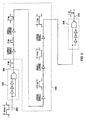
- Figure 4 is a schematic diagram of a typical decode path for a RAM;
- Figure 5 is a schematic diagram of an exemplary input buffer for a synchronous RAM using the skewed logic technique of the present invention;
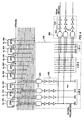
- Figure 6 is a schematic diagram of an exemplary predecoder for a synchronous RAM using the skewed logic technique of the present invention;
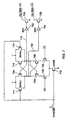
- Figure 7 is a schematic diagram of an exemplary differential sense amplifier for a synchronous RAM using the skewed logic technique of the present invention; and
- Figure 8 shows complementary data paths for the skewed logic technique of the present invention.
-
- Figures 1A and 1B show two
CMOS inverter chains effective capacitive load 104 of equal value.Inverter chain 100 is a typical prior art buffering circuit with a chain of six serially connectedCMOS inverters input signal 200. The width of each transistor is shown in Figures 1A and 1B in parentheses withPMOS transistor 106P being 3 µ wide andNMOS transistor 106N being 2 µ wide. In this example, the size of each inverter grows by a factor of three, starting from a PMOS/NMOS channel width ratio of 3/2 forinverter 106 to 729/486 for thelast inverter 116. Defining the fanout for each individual transistor as the ratio of the sum of the transistor sizes (channel widths) of the load (i.e., total width of transistor gates being driven) divided by the size of the driver transistor yields a fanout Fp of 5 (5 = [9+6]/3 = [27+18]/9 = [81+54]/27 = etc.) for thePMOS transistors NMOS transistors - Referring to Figure 1B,
inverter chain 102 includes four serially connectedCMOS inverters first inverter 118 has an NMOS transistor with a size, for example, four times that of the PMOS transistor, resulting in a much faster falling transition on node 118OUT than rising transition. To achieve high speed for the fast (information carrying) path ofinverter chain 102, the fanout Fn of NMOS transistor 118N is chosen to be 7.5, the same value as used fortransistor 106N in Figure 1A. The sum of channel widths for theload transistors 120P and 120N is thus designed to be 7.5 times larger than the 4 µ channel width of the driver transistor 118N, for a total channel width fortransistors 120P and 120N of 30 µ. To speed up the rise time of the signal at the output ofinverter 120, PMOS transistor 120P is made much larger thanNMOS transistor 120N. In the example shown, PMOS/NMOS transistor sizes forinverter 120 is set at 25/5. This speeds up the rise time of the signal at the output ofinverter 120 at the cost of slower fall time, while maintaining a total of 30 microns for the transistor channel sizes. The same analysis applies in choosing the transistor channel widths for the twofinal inverters inverters - The Fp for
inverter 120 is 125/25 = 5, and the Fn forinverter 122 is 825/110 = 7.5. - To compare the performance of each inverter chain, assume that each consecutive pair of inverters in
inverter chain 100 exhibits a propagation delay of, for example, 1 nsec. Given the same fanout for the fast path (i.e., rising edge of input) for the twoinverter chains inverter chain 102 is actually smaller than that ofinverter chain 100. As theinput signal 200 makes a transition from low to high, the gate to source voltage ofPMOS transistors inverters NMOS transistors 106N and 118N increases. The NMOS transistors thus start to turn on and the PMOS transistors start to turn off, pulling the inverter outputs down toward ground. Initially, however, in pulling the outputs down toward ground, the NMOS transistors must fight the PMOS transistors that are not yet completely OFF. During this period, relatively strong NMOS 118N fights a muchweaker PMOS 118P, as compared toNMOS 106N that fights a comparablystrong PMOS 106P. Given the same capacitive fanout Fn=7.5 for the NMOS transistors, the signal 118OUT at the output ofinverter 118 will therefore drop to ground faster than the signal 106OUT at the output ofinverter 106. That is, for a rising input, skewedinverter 118 exhibits less delay thannormal inverter 106. Similarly, when the outputs of thefirst inverters PMOS transistors 108P and 120P and turn offNMOS transistors small NMOS transistor 120N offers little opposition to large PMOS transistor 120P, whileNMOS transistor 108N initially offers substantial opposition toPMOS transistor 108P. Given the same capacitive fanout of Fp=5 for the PMOS transistors, signal 120OUT at the output ofinverter 120 will therefore rise to VDD faster than signal 108OUT at the output ofinverter 108. Accordingly, the average delay per pair of stages for skewedinverter chain 102 for a rising input is less than that ofinverter chain 100, possibly 0.9 nsec. The total delay forinverter chain 100 is therefore equal to 3ns (six stages of 0.5 nsec. delay each), while the total delay for a rising input for skewedinverter chain 102 is 1.8ns (four stages of 0.45 nsec. delay each). Note that PMOS transistor 124P infinal inverter 124 ininverter chain 102 is even stronger than PMOS transistor 116P infinal inverter 116 ininverter chain 100. Therefore,inverter chain 102 with two less stages is capable of driving even a larger load, much faster than possible withinverter chain 100. The delay for a rising input for the skewed logic is only about 60% that of normal logic for the same total fanout. - The significant increase in the speed through
circuit 120 at the rising edge of the input signal, however, is realized at the expense of substantially increased delay at the falling edge of the input signal. The priorart signal path 100 exhibits equal delay for either rising or falling inputs. Butsignal path 102 according to the present invention is very slow in propagating a falling edge on its input. When the input switches low,PMOS transistor 118P is very slow to switch node 118OUT high for two reasons. First,PMOS transistor 118P has a very high fanout of [25+5]/1 = 30. Such large fanout by itself makesPMOS transistor 118P very slow. Secondly, NMOS transistor 118N continues to successfully fightPMOS transistor 118P untilinput 200 reaches a low enough voltage to turn off NMOS transistor 118N. Thus, node 118OUT switches high after a negative transition on the input at a considerably slower rate than does node 106OUT incircuit 100. Similarly,NMOS transistor 120N ofstage 120 is very slow to pull node 120OUT low. Thus, as shown in Figure 2, the skewed logic ofcircuit 102 is faster than theprior art circuit 100 on the leading (rising) edge of the input, but much slower than theprior art circuit 100 on the trailing (falling) edge of the input signal. The increased delay at the trailing edge, however, has absolutely no adverse consequences on the operation of the circuit of the present invention. That is so because the pulse is terminated before the next information carrying leading edge of a pulse occurs. - Due to the slower second edge, however, the width of the pulse grows by a considerable amount as the pulse propagates through each stage of the skewed inverter chain. As shown in Figure 2, the positive pulse on node 124OUT is wider than the negative pulse on node 122OUT which in turn is wider than the positive pulse on node 120OUT, etc. The width of the pulse can be permitted to grow significantly without incurring any penalties, but the circuit must be designed to ensure that, even in the last stage of logic, the pulse terminates before the next information carrying edge occurs. To ensure such timely termination, the skewed logic technique of the present invention is applicable in those circuits where the information carrying edge of the signal does not occur at random times, but is limited to occurring only with known minimum time intervals between initiation of new information carrying pulse edges. This ensures that one data carrying pulse terminates before arrival of a new data carrying pulse.
- For proper operation of the circuit, the designer must limit the pulse width of the signal propagating through the signal path. This can be achieved by generating a very narrow pulse at the information carrying edge of the signal using, for example, a simple one-shot circuit. Instead of the original input signal, the narrow pulse is entered into the skewed logic. As the narrow pulse propagates through the skewed logic path, its pulse width grows. When the pulse width of the signal reaches critical size (less than the minimum cycle time), the signal may once again be put through a one-shot circuit to generate a second narrow pulse which continues to propagate through additional stages of skewed logic. This regeneration of a narrow pulse can be performed as often as deemed desirable.
- Figure 3 provides a simple example of skewed logic according to the present invention. An
input signal 300 is applied to the input of a one-shot circuit 302. Theoutput 304 of one-shot circuit 302 is a narrow negative pulse at the rising edge of the input signal. This signal propagates through several stages of skewed logic 306. In this example, the PMOS/NMOS size ratios are skewed to minimize delay through the circuit on the falling edge of the signal onnode 304. The narrow pulse grows in width as it propagates through each stage of skewed logic 306. When the pulse width approaches the minimum cycle time of the input signal (i.e., time between initiation of new information carrying pulses), a second one-shot circuit 308 receives the signal at its input to generate a second narrow pulse at itsoutput 310. This process continues until the signal reaches the output. It is to be understood that many of the skewed inverters 306 may be NAND, NOR or other logic gates in a typical application. - The skewed logic technique of the present invention requires that data be represented by pulses on complementary or mutually exclusive data lines as opposed to voltage levels. That is, data is not transmitted through a single wire using voltage levels to distinguish between a logic "0" and a logic "1." Instead, at least two mutually exclusive wires are required such that a pulse on the true wire represents a logic "1" while a mutually exclusive pulse on the inverse wire represents a logic "0." For example, in the case of a predecoder or final decoder output in a random access memory circuit, a pulse exists on a selected one of N outputs to the exclusion of a pulse on any other output. Each pulse is allowed to propagate through a separate skewed logic path. Separate data paths are illustrated by the exemplary circuit shown in Figure 8. An input signal and its inverse are applied respectively to the inputs of two
pulse generators pulse generators true path 804 drives the gate of a PMOS pull-uptransistor 808 through an inverter, while the output of the inverse path 806 drives the gate of an NMOS pull-down transistor 810 directly. The drains ofPMOS transistor 808 andNMOS transistor 810 connect together to form a single output wire. A rising edge at the input results in a negative pulse at the output of one-shot 800 whose leading edge rapidly propagates through skewedlogic 804 and arrives as a much wider negative pulse at the gate ofPMOS transistor 808, while the gate ofNMOS transistor 810 remains at logic low. This causesPMOS transistor 808 to pull output node OUT up to VDD with little total delay. A falling edge at the input results in a negative pulse at the output of one-shot 802 whose leading edge rapidly propagates through skewed logic 806 and arrives as a much wider positive pulse at the gate ofNMOS transistor 810, while the gate ofPMOS transistor 808 remains at logic high. This causes the output node OUT to be pulled low to ground. In some applications a small latch may be required on the output wire to indefinitely hold the data represented by the most recently received pulse. Thus, the speed advantages of the skewed logic technique of the present invention can be realized in both directions of an input signal, on a single output wire but with two separate signal paths. - This example also illustrates the requirement of a minimum time interval between the occurrence of two information carrying edges. That is, a negative transition at IN cannot be permitted to follow too closely after a positive transition, or vice versa. A very narrow pulse generated at the output of one-
shot 800 grows to a substantially wider pulse at the gate ofPMOS transistor 808. If a subsequent negative transition at IN occurred early enough such thatNMOS transistor 810 turns on beforePMOS transistor 808 turns off, the output is very slow to fall, if it falls at all, and the circuit consumes excessive power. Thus, it is critical to the skewed logic technique of the present invention that the information carrying edge of the signal does not occur at random times. There must be sufficient time allowed between information carrying pulses to allow the previous information carrying edge to have already terminated before arrival of a new, possibly opposite, information carrying edge. - A good example of an application circuit for the skewed logic technique of the present invention is a dynamic or static synchronous random access memory circuit. The design of synchronous memory circuits is based on a master clock signal. A dynamic random access memory (DRAM) cycle, such as Write or Read is initiated at the rising edge (arbitrary choice) of the clock input signal. The column addresses supplied to synchronous DRAMs are sampled on (or latched by) the rising edge of the periodic clock, and cannot change internally between clocks. A synchronous DRAM does not support a Read/Modify/Write cycle which would require maintaining column decode signal selected for a possible Write cycle after a Read operation. A single known operation (e.g., read or write) allows the use of a pulse rather than a level on the final column decode output. This combined with the periodic change in internal address allows the use of skewed logic. Thus, the speed benefits of skewed logic are realized while simultaneously achieving a wider pulse than is possible with post charge logic for read or write on the column select output. These advantages will be explained in greater detail hereinafter.
- Figure 4 is a simplified schematic diagram of a typical decode scheme used in DRAMs. Address information having, for example, eight bits is applied to eight corresponding input buffers 400. A
predecoder stage 402 divides the address bits into, for example, two groups of three bits and a group of two bits.Predecoder 402 typically includes three-input NAND gates 404 followed by a chain ofdriver inverters 406 that progressively grow in size.Predecoder 402 selects one of eight global predecode lines for the two three-bit groups and one of four for the two-bit group. Global predecode lines are then input to afinal decode stage 408 which includes three-input NAND gates 410 followed by a chain ofdriver inverters 412 that progressively grow in size. Thefinal decode stage 408 selects one of 256 to generate the final global column decode line which selects a particular column in each of many memory arrays. - In synchronous DRAMs, the address at the input of the input buffers 400 is sampled (or latched) on a given, for example, rising edge of the master clock signal.
Block 400 of Figure 5 is a schematic diagram of an exemplary synchronous DRAM address input buffer using skewed logic according to the present invention. The address at aninput pad 500 is buffered using series connectedinverters inverter 504 connects to one input of a two-input NAND gate 506 which has aninverter 508 connected to its output. The output ofinverter 508 forms the true output OUT of the input buffer circuit. The output of thefirst inverter 502 connects to one input of another two-input NAND gate 510 whose output connects to an input of aninverter 512. The output ofinverter 512 forms the complement output /OUT of the input buffer circuit. The second input of bothNAND gates shot circuit 514 is followed by aninverter 516 whose output is the STROBE signal. STROBE is a very narrow positive pulse on the rising (leading) edge of the clock input. Skewed logic is utilized in this circuit to reduce the delay for the leading edge of the address signal. Thus,NAND gates inverters Inverter 516 and one-shot 514 have PMOS/NMOS transistor size ratios skewed to minimize the delay for, in this example, the rising edge of the CLK IN signal.Inverters - The combination of a logical "1" (VDD) at
address input 500 with a positive pulse at STROBE results in a positive pulse at OUT with /OUT remaining at ground. The combination of a logical "0" (ground) ataddress input 500 and a positive pulse at STROBE results in a positive pulse at /OUT, with OUT remaining at ground. Due to the skewing of transistor sizes, however, the signal at OUT and /OUT is a pulse somewhat wider than the STROBE pulse. - Address pulses on OUT or /OUT feed into predecoders. Figure 6 is an exemplary circuit schematic of a synchronous DRAM predecoder according to the present invention. Three address bits Ai, Aj, and Ak connect to gate terminals of three
NMOS transistors precharged decode node 606 to ground, thus performing NAND logic. Afourth NMOS transistor 608 receives the complement of Ai (least significant bit) at its gate terminal and connectstransistors precharged decode node 610.Node 606 thus decodesaddress 111, andnode 610 decodesaddress 110. Three other similar circuits with other values for Aj and Ak generate six other outputs.PMOS transistors precharge decode nodes Inverters node 606 to drive the high capacitive load on the output ofinverter 620. These skewed inverter have exemplary PMOS/NMOS channel width ratios of 80/20, 80/160, and 700/170, respectively.Inverters node 610 with similar PMOS/NMOS ratios. This skewing significantly decreases the delay for the leading edge of signals at the outputs of the inverter chains. - The pulse width of the signal at the outputs however further increases due to the increased delay through the circuit on the trailing edge of the pulse. The pulse width of a global decode signal at the output of a final decoder (408 in Figure 4) is even further increased due to similar skewing in favor of the leading edge of the pulse. The pulse width can be allowed to increase up to but not exceed the minimum cycle time for which proper operation is required. If the cycle time is equal to the stretched width of the pulse at the global decoder output, one global column select is deselected simultaneously with the selection of another. In the event the same column is selected in two successive cycles, it simply remains on for the two cycles, which is not possible with post charge logic. Thus, the skewed logic technique of the present invention allows a global column decode line to be on for as long as a full clock cycle, achieving twice the memory bandwidth for a given select time as compared to that possible with post charge logic.
- The global decode signal typically connects a selected pair of Bit and /Bit lines to a pair of complementary local input/output (I/O) lines. Upon activation of a global decode signal in a Read cycle, the local I/O lines develop a differential signal whose polarity depends on the data stored in the selected memory cell. The local I/O lines connect to the inputs of a differential sense amplifier whose outputs generate a pulse on a true or complement global I/O line. At this location, it is convenient to reduce the pulse width of the signal by controlling the activation signal for the differential sense amplifier. Figure 7 is a circuit schematic of an exemplary dynamic differential sense amplifier for synchronous RAMs according to the present invention. A pair of
NMOS input transistors NMOS transistors PMOS transistors NMOS transistor 712 andPMOS transistors - Before generation of the narrow positive pulse, a logical low at the strobe inputs brings both outputs of the amplifier at
nodes PMOS transistors NMOS transistor 712 turns ON. This allows the cross-coupled transistors to start the regenerative process such that when I/O is at a more positive voltage than /I/O, it rapidly bringsoutput node 720 to ground and leaves itscomplement node 718 at VDD. If /I/O is at a more positive voltage than I/O when STROBE pulse arrives, then the cross-coupled transistors bringnode 718 to ground and leavenode 720 at VDD. The skewed logic technique can be utilized inside the amplifier by making the NMOS pull-down transistor 712 large compared to the PMOS pull-uptransistors output node transistors strong NMOS transistor 712. Twoinverters transistors - In conclusion, the present invention provides a fast propagation technique for CMOS circuits. By skewing the transistor sizes of the CMOS circuit, the technique of the present invention speeds up the information carrying edge of the propagating signal at the cost of slower opposite edge. This speeds up the access time of the circuit compared to that possible using normal (unskewed) logic stages. The technique can be employed in those CMOS circuits where information can not change at random times, but instead changes only at known specific times. A good example of an application for the technique of the present invention is a CMOS synchronous DRAM or SRAM circuit where access time is one of the most critical design considerations. The skewed logic technique of the present invention allows a column select line to be on for a full clock cycle, thus significantly increasing the memory time available to write or to develop a signal for read as compared to that available with post charge logic.
Claims (3)
- CMOS synchronous random access memory circuit wherein information carrying edges of data occur according to a master clock signal (CLK IN) defining a memory cycle, comprising
a pulse generator (514) with an input for receiving the master clock signal (CLK IN) and an output for providing a narrow strobe pulse (STROBE) at the information carrying edge of the master clock signal (CLK IN) and no pulse on the opposite edge of the master clock signal (CLK IN),
an address input buffer (400-0) having an input for receiving an address information (A0) of a memory cell to be addressed and an output (OUT), for regenerating the address information (A0) as a narrow pulse upon being strobed by the strobe pulse (STROBE), and
a decoder (402, 408) having an input coupled to the output (OUT) of the address input buffer (400-0) and an output (FINAL DECODE) coupled to the memory cell,
characterised by
a skewed logic stage comprising a P-channel pull-up transistor and an N-channel pull-down transistor each receiving the narrow pulse at a gate terminal, wherein the sizes of the P-channel and N-channel transistors are ratioed to obtain fast signal transition through the skewed logic stage for a first edge of the narrow pulse and slow signal transition for a second opposite edge, wherein the slow signal transition causes the width of the narrow pulse to grow,
wherein the skewed logic stage is comprised in the address input buffer (400-0), a plurality of serially coupled skewed logic stages is comprised in a decode stage of the decoder, and/or the skewed logic stage is comprised in a differential sense amplifier having a first and a second input coupled to the complimentary pair of input/output lines (I/O, /I/O) and a first and a second output coupled to a complimentary pair of global input/output lines (GLOBAL I/O, GLOBAL /I/O), the differential sense amplifier being strobed by the strobe pulse (STROBE) to generate a narrow pulse corresponding to a signal on the complementary pair of input/output lines (I/O, /I/O). - Memory circuit according to claim 1 characterized in that the address input buffer (400-0) comprises a CMOS inverter (508, 512) forming a second skewed logic stage having an input coupled to an output of the first skewed logic stage, for driving the output of the address input buffer (400-0).
- Memory circuit according to claim 1 or 2, characterized in that the differential sense amplifier comprises a CMOS inverter skewed logic stage having an input coupled to the output of the differential sense amplifier for driving the output.
Applications Claiming Priority (3)
| Application Number | Priority Date | Filing Date | Title |
|---|---|---|---|
| US08/269,451 US5519344A (en) | 1994-06-30 | 1994-06-30 | Fast propagation technique in CMOS integrated circuits |
| US269451 | 1994-06-30 | ||
| EP95109976A EP0690577B1 (en) | 1994-06-30 | 1995-06-27 | CMOS integrated circuit for fast propagation of a signal edge |
Related Parent Applications (1)
| Application Number | Title | Priority Date | Filing Date |
|---|---|---|---|
| EP95109976A Division EP0690577B1 (en) | 1994-06-30 | 1995-06-27 | CMOS integrated circuit for fast propagation of a signal edge |
Publications (2)
| Publication Number | Publication Date |
|---|---|
| EP1069685A1 EP1069685A1 (en) | 2001-01-17 |
| EP1069685B1 true EP1069685B1 (en) | 2004-10-20 |
Family
ID=23027312
Family Applications (2)
| Application Number | Title | Priority Date | Filing Date |
|---|---|---|---|
| EP00122120A Expired - Lifetime EP1069685B1 (en) | 1994-06-30 | 1995-06-27 | Fast propagation technique in CMOS integrated circuits |
| EP95109976A Expired - Lifetime EP0690577B1 (en) | 1994-06-30 | 1995-06-27 | CMOS integrated circuit for fast propagation of a signal edge |
Family Applications After (1)
| Application Number | Title | Priority Date | Filing Date |
|---|---|---|---|
| EP95109976A Expired - Lifetime EP0690577B1 (en) | 1994-06-30 | 1995-06-27 | CMOS integrated circuit for fast propagation of a signal edge |
Country Status (7)
| Country | Link |
|---|---|
| US (1) | US5519344A (en) |
| EP (2) | EP1069685B1 (en) |
| JP (1) | JP3129938B2 (en) |
| KR (1) | KR100397360B1 (en) |
| CN (1) | CN1093702C (en) |
| DE (2) | DE69520620T2 (en) |
| TW (1) | TW338190B (en) |
Families Citing this family (52)
| Publication number | Priority date | Publication date | Assignee | Title |
|---|---|---|---|---|
| JP3537500B2 (en) * | 1994-08-16 | 2004-06-14 | バー−ブラウン・コーポレーション | Inverter device |
| US6246278B1 (en) * | 1995-12-22 | 2001-06-12 | Lsi Logic Corporation | High speed single phase to dual phase clock divider |
| US5701275A (en) * | 1996-01-19 | 1997-12-23 | Sgs-Thomson Microelectronics, Inc. | Pipelined chip enable control circuitry and methodology |
| US5801563A (en) * | 1996-01-19 | 1998-09-01 | Sgs-Thomson Microelectronics, Inc. | Output driver circuitry having a single slew rate resistor |
| US5926050A (en) * | 1996-07-29 | 1999-07-20 | Townsend And Townsend And Crew Llp | Separate set/reset paths for time critical signals |
| US5929680A (en) * | 1997-05-16 | 1999-07-27 | Tritech Microelectronics International Ltd | Short circuit reduced CMOS buffer circuit |
| JP2000188534A (en) | 1998-04-23 | 2000-07-04 | Hewlett Packard Co <Hp> | Clock buffer circuit device |
| US5982700A (en) * | 1998-05-21 | 1999-11-09 | Integrated Device Technology, Inc. | Buffer memory arrays having nonlinear columns for providing parallel data access capability and methods of operating same |
| US5999478A (en) * | 1998-05-21 | 1999-12-07 | Integrated Device Technology, Inc. | Highly integrated tri-port memory buffers having fast fall-through capability and methods of operating same |
| US6216205B1 (en) | 1998-05-21 | 2001-04-10 | Integrated Device Technology, Inc. | Methods of controlling memory buffers having tri-port cache arrays therein |
| US5978307A (en) * | 1998-05-21 | 1999-11-02 | Integrated Device Technology, Inc. | Integrated circuit memory devices having partitioned multi-port memory arrays therein for increasing data bandwidth and methods of operating same |
| US6154045A (en) * | 1998-12-22 | 2000-11-28 | Intel Corporation | Method and apparatus for reducing signal transmission delay using skewed gates |
| JP4101973B2 (en) * | 1999-05-21 | 2008-06-18 | 株式会社ルネサステクノロジ | Output buffer circuit |
| US6359477B1 (en) * | 1999-06-03 | 2002-03-19 | Texas Instruments Incorporated | Low power driver design |
| US6552589B1 (en) * | 1999-10-21 | 2003-04-22 | International Business Machines Corporation | Method and apparatus for process independent clock signal distribution |
| JP2001274672A (en) * | 2000-01-21 | 2001-10-05 | Seiko Epson Corp | Try-state buffer circuit |
| US6492836B2 (en) * | 2000-11-30 | 2002-12-10 | Infineon Technologies Ag | Receiver immune to slope-reversal noise |
| US6552953B2 (en) * | 2001-02-05 | 2003-04-22 | Micron Technology, Inc. | High speed signal path and method |
| TW526465B (en) * | 2001-04-27 | 2003-04-01 | Toshiba Corp | Display apparatus, digital/analog converting circuit and digital/analog converting method |
| US7136058B2 (en) * | 2001-04-27 | 2006-11-14 | Kabushiki Kaisha Toshiba | Display apparatus, digital-to-analog conversion circuit and digital-to-analog conversion method |
| US6628139B2 (en) * | 2001-08-03 | 2003-09-30 | Micron Technology, Inc. | Digital logic devices with extremely skewed trip points and reset circuitry for rapidly propagating signal edges |
| US6927613B2 (en) * | 2001-09-07 | 2005-08-09 | Freescale Semiconductor, Inc. | Circuit generating constant narrow-pulse-width bipolarity cycle monocycles using CMOS circuits |
| US6784689B2 (en) * | 2002-02-06 | 2004-08-31 | Sun Microsystems, Inc. | Transmission gate based signal transition accelerator |
| US6785875B2 (en) * | 2002-08-15 | 2004-08-31 | Fulcrum Microsystems, Inc. | Methods and apparatus for facilitating physical synthesis of an integrated circuit design |
| CN100380811C (en) * | 2002-12-13 | 2008-04-09 | 株式会社半导体能源研究所 | Semiconductor device and display appliance using the semiconductor device |
| JP2004253880A (en) | 2003-02-18 | 2004-09-09 | Nec Electronics Corp | Semiconductor integrated circuit device |
| US6960950B2 (en) * | 2003-03-25 | 2005-11-01 | Intel Corporation | Circuit and method for generating a clock signal |
| US6911872B2 (en) * | 2003-03-25 | 2005-06-28 | Intel Corporation | Circuit and method for generating a clock signal |
| JP2004348573A (en) * | 2003-05-23 | 2004-12-09 | Renesas Technology Corp | Clock generation circuit and system including it |
| US6864726B2 (en) * | 2003-06-17 | 2005-03-08 | Intel Corporation | Output signal control from a DAC-driven amplifier-based driver |
| US7436215B2 (en) * | 2003-09-30 | 2008-10-14 | Intel Corporation | Transmitter |
| JP4683833B2 (en) | 2003-10-31 | 2011-05-18 | 株式会社半導体エネルギー研究所 | Functional circuit and design method thereof |
| US7078297B2 (en) * | 2004-05-28 | 2006-07-18 | Freescale Semiconductor, Inc. | Memory with recessed devices |
| US7208984B1 (en) * | 2004-07-15 | 2007-04-24 | Linear Technology Corporation | CMOS driver with minimum shoot-through current |
| US20060103422A1 (en) * | 2004-11-12 | 2006-05-18 | Richardson Kenneth G | Low leakage, source modulated, differential output level shifter |
| US8294503B1 (en) * | 2004-11-22 | 2012-10-23 | Marvell International Ltd. | Method and apparatus for reducing jitter in a transmitter |
| US7199616B2 (en) * | 2004-11-29 | 2007-04-03 | Exar Corporation | Method and apparatus to generate break before make signals for high speed TTL driver |
| US7170326B2 (en) * | 2005-01-06 | 2007-01-30 | Broadcom Corporation | Pulse-on-edge circuit |
| US7417482B2 (en) * | 2005-10-31 | 2008-08-26 | Qualcomm Incorporated | Adaptive voltage scaling for an electronics device |
| KR100691108B1 (en) * | 2005-12-28 | 2007-03-12 | 동부일렉트로닉스 주식회사 | Delay chain capable of reducing skew between input and output signals |
| US20080061829A1 (en) * | 2006-08-24 | 2008-03-13 | Sony Computer Entertainment Inc. | Methods and apparatus for reducing duty cycle distortion in a multiple-stage inverter |
| US20080136498A1 (en) * | 2006-12-06 | 2008-06-12 | Razieh Roufoogaran | Method and System for Buffering A Clock Signal |
| JP4543071B2 (en) * | 2007-10-12 | 2010-09-15 | 株式会社アドバンテスト | Delay device |
| US20090167395A1 (en) * | 2007-12-31 | 2009-07-02 | Texas Instruments Incorporated | High performance latches |
| KR101659840B1 (en) * | 2010-03-11 | 2016-09-30 | 삼성전자주식회사 | Digital DLL having duty correction circuit of skewed gate type and duty correction method thereof |
| US20130076424A1 (en) * | 2011-09-23 | 2013-03-28 | Qualcomm Incorporated | System and method for reducing cross coupling effects |
| EP3176770B1 (en) * | 2014-07-31 | 2019-03-27 | LG Display Co., Ltd. | Display device |
| US9979398B2 (en) * | 2015-05-06 | 2018-05-22 | Capital Microelectronics Co., Ltd. | Buffer circuit and electronic device using same |
| US9964832B2 (en) * | 2015-05-28 | 2018-05-08 | Futurewei Technologies, Inc. | Distributed mach-zehnder modulator (MZM) driver delay compensation |
| KR102555452B1 (en) * | 2018-08-16 | 2023-07-17 | 에스케이하이닉스 주식회사 | Semiconductor memory apparatus, operation method thereof, and system including the same |
| KR102060044B1 (en) * | 2018-09-13 | 2019-12-27 | 아주대학교산학협력단 | Pulse driver and the method for driving the same |
| US10587253B1 (en) | 2018-11-29 | 2020-03-10 | Qualcomm Incorporated | Ring oscillator-based programmable delay line |
Family Cites Families (14)
| Publication number | Priority date | Publication date | Assignee | Title |
|---|---|---|---|---|
| US4496857A (en) * | 1982-11-01 | 1985-01-29 | International Business Machines Corporation | High speed low power MOS buffer circuit for converting TTL logic signal levels to MOS logic signal levels |
| US4599528A (en) * | 1983-01-17 | 1986-07-08 | Commodore Business Machines Inc. | Self booting logical or circuit |
| JPS60154553A (en) * | 1984-01-23 | 1985-08-14 | Nec Corp | Driving method for complementary mos integrated circuit |
| EP0347759B1 (en) * | 1988-06-24 | 1994-08-10 | National Semiconductor Corporation | Speed enhancement technique for CMOS circuits |
| US4985643A (en) * | 1988-06-24 | 1991-01-15 | National Semiconductor Corporation | Speed enhancement technique for CMOS circuits |
| JPH088264B2 (en) * | 1988-06-30 | 1996-01-29 | 株式会社東芝 | Semiconductor integrated circuit |
| JPH0727717B2 (en) * | 1988-07-13 | 1995-03-29 | 株式会社東芝 | Sense circuit |
| JPH0334366A (en) * | 1989-06-29 | 1991-02-14 | Nec Corp | Cmos circuit |
| JP2728533B2 (en) * | 1990-01-19 | 1998-03-18 | 富士通株式会社 | Semiconductor device |
| US5061864A (en) * | 1990-06-18 | 1991-10-29 | National Semiconductor Corporation | Monophase logic |
| US5247212A (en) * | 1991-01-31 | 1993-09-21 | Thunderbird Technologies, Inc. | Complementary logic input parallel (clip) logic circuit family |
| JPH0668673A (en) * | 1992-08-24 | 1994-03-11 | Mitsubishi Denki Eng Kk | Semiconductor storage device |
| US5274277A (en) * | 1992-09-01 | 1993-12-28 | Intel Corporation | High speed "OR" circuit configuration |
| JPH0696589A (en) * | 1992-09-14 | 1994-04-08 | Nec Ic Microcomput Syst Ltd | Semiconductor memory |
-
1994
- 1994-06-30 US US08/269,451 patent/US5519344A/en not_active Expired - Lifetime
-
1995
- 1995-06-24 TW TW084106511A patent/TW338190B/en not_active IP Right Cessation
- 1995-06-27 EP EP00122120A patent/EP1069685B1/en not_active Expired - Lifetime
- 1995-06-27 EP EP95109976A patent/EP0690577B1/en not_active Expired - Lifetime
- 1995-06-27 DE DE69520620T patent/DE69520620T2/en not_active Expired - Lifetime
- 1995-06-27 DE DE69533678T patent/DE69533678T2/en not_active Expired - Lifetime
- 1995-06-29 KR KR1019950019328A patent/KR100397360B1/en not_active IP Right Cessation
- 1995-06-30 CN CN95107431A patent/CN1093702C/en not_active Expired - Fee Related
- 1995-06-30 JP JP07165968A patent/JP3129938B2/en not_active Expired - Fee Related
Also Published As
| Publication number | Publication date |
|---|---|
| DE69520620T2 (en) | 2001-10-11 |
| KR100397360B1 (en) | 2003-11-13 |
| DE69520620D1 (en) | 2001-05-17 |
| CN1093702C (en) | 2002-10-30 |
| TW338190B (en) | 1998-08-11 |
| DE69533678D1 (en) | 2004-11-25 |
| JPH08181596A (en) | 1996-07-12 |
| EP0690577A1 (en) | 1996-01-03 |
| US5519344A (en) | 1996-05-21 |
| JP3129938B2 (en) | 2001-01-31 |
| DE69533678T2 (en) | 2006-02-09 |
| KR960002346A (en) | 1996-01-26 |
| EP0690577B1 (en) | 2001-04-11 |
| CN1117671A (en) | 1996-02-28 |
| EP1069685A1 (en) | 2001-01-17 |
Similar Documents
| Publication | Publication Date | Title |
|---|---|---|
| EP1069685B1 (en) | Fast propagation technique in CMOS integrated circuits | |
| US5343090A (en) | Speed enhancement technique for CMOS circuits | |
| US6949948B2 (en) | Digital logic devices with extremely skewed trip points and reset circuitry for rapidly propagating signal edges | |
| US4574203A (en) | Clock generating circuit providing a boosted clock signal | |
| JP3526921B2 (en) | Latch control type output driver | |
| JPH05290581A (en) | Output driver circuit for pre-charging | |
| EP0096421B1 (en) | Static memory device with signal transition detector | |
| JPH09116423A (en) | Wave propagation logic | |
| CN1140904C (en) | Synchronous semiconductor memory device with clock generating circuit | |
| US6469953B1 (en) | Latch circuit | |
| US5889416A (en) | Symmetrical nand gates | |
| US5448529A (en) | High speed and hierarchical address transition detection circuit | |
| US5263173A (en) | High speed clocked output driver for switching logic levels of an output pad at integer and integer and a half clock cycles | |
| US6998878B2 (en) | Semiconductor integrated circuit and semiconductor logic circuit used in the integrated circuit | |
| US6097222A (en) | Symmetrical NOR gates | |
| US5394363A (en) | Pulse write driver circuit | |
| CA1320544C (en) | Speed enhancement technique for cmos circuits | |
| US6292405B1 (en) | Data output buffer with precharge | |
| EP0489734B1 (en) | High-speed dynamic cmos circuit | |
| JP2538628B2 (en) | Semiconductor integrated circuit | |
| KR0172514B1 (en) | Fast output buffer | |
| KR0136826Y1 (en) | Data output buffer | |
| JPH09331238A (en) | Semiconductor integrated circuit | |
| EP0395213A2 (en) | Decoder | |
| KR20000041582A (en) | Differential amplifier with high speed |
Legal Events
| Date | Code | Title | Description |
|---|---|---|---|
| PUAI | Public reference made under article 153(3) epc to a published international application that has entered the european phase |
Free format text: ORIGINAL CODE: 0009012 |
|
| 17P | Request for examination filed |
Effective date: 20001012 |
|
| AC | Divisional application: reference to earlier application |
Ref document number: 690577 Country of ref document: EP |
|
| AK | Designated contracting states |
Kind code of ref document: A1 Designated state(s): DE GB NL |
|
| AKX | Designation fees paid |
Free format text: DE GB NL |
|
| 17Q | First examination report despatched |
Effective date: 20030327 |
|
| GRAP | Despatch of communication of intention to grant a patent |
Free format text: ORIGINAL CODE: EPIDOSNIGR1 |
|
| GRAA | (expected) grant |
Free format text: ORIGINAL CODE: 0009210 |
|
| GRAS | Grant fee paid |
Free format text: ORIGINAL CODE: EPIDOSNIGR3 |
|
| AC | Divisional application: reference to earlier application |
Ref document number: 0690577 Country of ref document: EP Kind code of ref document: P |
|
| AK | Designated contracting states |
Kind code of ref document: B1 Designated state(s): DE GB NL |
|
| REG | Reference to a national code |
Ref country code: GB Ref legal event code: FG4D |
|
| REF | Corresponds to: |
Ref document number: 69533678 Country of ref document: DE Date of ref document: 20041125 Kind code of ref document: P |
|
| PLBE | No opposition filed within time limit |
Free format text: ORIGINAL CODE: 0009261 |
|
| STAA | Information on the status of an ep patent application or granted ep patent |
Free format text: STATUS: NO OPPOSITION FILED WITHIN TIME LIMIT |
|
| 26N | No opposition filed |
Effective date: 20050721 |
|
| PGFP | Annual fee paid to national office [announced via postgrant information from national office to epo] |
Ref country code: NL Payment date: 20120614 Year of fee payment: 18 Ref country code: DE Payment date: 20120531 Year of fee payment: 18 |
|
| PGFP | Annual fee paid to national office [announced via postgrant information from national office to epo] |
Ref country code: GB Payment date: 20120601 Year of fee payment: 18 |
|
| REG | Reference to a national code |
Ref country code: NL Ref legal event code: V1 Effective date: 20140101 |
|
| GBPC | Gb: european patent ceased through non-payment of renewal fee |
Effective date: 20130627 |
|
| REG | Reference to a national code |
Ref country code: DE Ref legal event code: R119 Ref document number: 69533678 Country of ref document: DE Effective date: 20140101 |
|
| PG25 | Lapsed in a contracting state [announced via postgrant information from national office to epo] |
Ref country code: GB Free format text: LAPSE BECAUSE OF NON-PAYMENT OF DUE FEES Effective date: 20130627 Ref country code: NL Free format text: LAPSE BECAUSE OF NON-PAYMENT OF DUE FEES Effective date: 20140101 Ref country code: DE Free format text: LAPSE BECAUSE OF NON-PAYMENT OF DUE FEES Effective date: 20140101 |