EP1070413B1 - Composite trunking in a router - Google Patents
Composite trunking in a router Download PDFInfo
- Publication number
- EP1070413B1 EP1070413B1 EP99917557A EP99917557A EP1070413B1 EP 1070413 B1 EP1070413 B1 EP 1070413B1 EP 99917557 A EP99917557 A EP 99917557A EP 99917557 A EP99917557 A EP 99917557A EP 1070413 B1 EP1070413 B1 EP 1070413B1
- Authority
- EP
- European Patent Office
- Prior art keywords
- trunk
- composite
- router
- routing
- trunks
- Prior art date
- Legal status (The legal status is an assumption and is not a legal conclusion. Google has not performed a legal analysis and makes no representation as to the accuracy of the status listed.)
- Expired - Lifetime
Links
Images

Classifications
-
- H—ELECTRICITY
- H04—ELECTRIC COMMUNICATION TECHNIQUE
- H04L—TRANSMISSION OF DIGITAL INFORMATION, e.g. TELEGRAPHIC COMMUNICATION
- H04L12/00—Data switching networks
- H04L12/28—Data switching networks characterised by path configuration, e.g. LAN [Local Area Networks] or WAN [Wide Area Networks]
-
- H—ELECTRICITY
- H04—ELECTRIC COMMUNICATION TECHNIQUE
- H04L—TRANSMISSION OF DIGITAL INFORMATION, e.g. TELEGRAPHIC COMMUNICATION
- H04L45/00—Routing or path finding of packets in data switching networks
- H04L45/02—Topology update or discovery
- H04L45/04—Interdomain routing, e.g. hierarchical routing
-
- Y—GENERAL TAGGING OF NEW TECHNOLOGICAL DEVELOPMENTS; GENERAL TAGGING OF CROSS-SECTIONAL TECHNOLOGIES SPANNING OVER SEVERAL SECTIONS OF THE IPC; TECHNICAL SUBJECTS COVERED BY FORMER USPC CROSS-REFERENCE ART COLLECTIONS [XRACs] AND DIGESTS
- Y10—TECHNICAL SUBJECTS COVERED BY FORMER USPC
- Y10S—TECHNICAL SUBJECTS COVERED BY FORMER USPC CROSS-REFERENCE ART COLLECTIONS [XRACs] AND DIGESTS
- Y10S370/00—Multiplex communications
- Y10S370/901—Wide area network
- Y10S370/902—Packet switching
Definitions
- IP Internet protocol
- TCP/IP Transmission Control Protocol
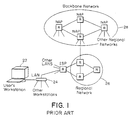
- the Internet is arranged as a hierarchy of networks.
- a typical end-user has a workstation 22 connected to a local-area network or LAN 24.
- the LAN is connected via a router R to a regional network 26 that is maintained and operated by a Regional Network Provider or RNP.
- the connection is often made through an Internet Service Provider or ISP.
- the regional network connects to the backbone network 28 at a Network Access Point (NAP).
- NAP Network Access Point
- the NAPs are usually located only in major cities.
- the network is made up of links and routers R.
- the links are usually fiber optic communication channels operating using the SONET (synchronous optical network) protocol.
- SONET links operate at a variety of data rates ranging from OC-3 (155Mb/s) to OC-192 (9.9Gb/s). These links, sometimes called trunks, move data from one point to another, often over considerable distances.
- Routers connect a group of links together and perform two functions:
- networks have added multiple links or trunks between network access points to scale bandwidth at a rate faster than the increase in individual link bandwidth. These multiple trunks may be transmitted on separate fibers or as separate channels wave-division multiplexed over a single fiber, or both.
- Wavelength-division multiplexing is an approach to increasing bandwidth between NAPs by multiplexing several channels on a single fiber.
- an existing fiber between two NAPs, which originally carried a single channel is enabled to handle a number (typically 20) channels of the same rate.
- a WDM multiplexer is used to combine several channels by modulating each with a slightly different optical wavelength or color of light. The channels, each at a different wavelength, are then combined into a single optical fiber. At the far end of the fiber, separating out the different, colors of light demultiplexes the channels. Upgrading one or more fibers to WDM results in large numbers of parallel trunks between NAPs.
- Multilink PPP One Big Virtual WAN Pipe
- Earlier routers treat each of the multiple trunks between two NAPs, and hence two routers, as ordinary links. Each trunk is connected to a router port and all traffic is forwarded over a specific trunk. This has two significant disadvanges: the complexity of the routing table is increased, and it becomes difficult to balance load across the trunks. Instead of simply directing all westbound traffic out of New York to Chicago, for example, with prior art routers it is necessary to direct distinct portions of this traffic over each of the N trunks between the two cities. The traffic is divided over these trunks by making a different routing table entry for each portion of traffic to direct it over a particular trunk.
- Earlier routers also have difficulty balancing the load across the set of trunks between two points. Traffic is divided over these trunks by the routing table and hence by destination address. At different points in time, the traffic to a set of destinations mapped to one trunk may be greater than the traffic to the set of destinations mapped to a second trunk leading to load imbalance between the trunks.
- a network router comprising a plurality of trunk ports and a routing fabric of plural nodes for transfer to data packets between trunk input and output ports at respective nodes, paths between input and output ports including multiple hops through nodes of the fabric, characterized by: a composite port of plural output ports to plural trunks which serve as a composite trunk to a common destination; the composite port including ports from said plural nodes; and an output port selector at each input mode which selects an output port for a packet from the composite port.
- Another aspect of the invention provides a method of routing a packet in a network according to claim 14.
- the router of the invention overcomes the limitation of prior art routers by treating all of the links or trunks to a given destination as a single composite trunk. With composite trunking, all of the westbound traffic out of New York, for example, would be directed onto the single composite trunk to Chicago rather than be divided into N separate portions, one for each of the N links to Chicago.
- the routing table lookup selects the composite trunk to Chicago as the outgoing link for the packet.
- a separate trunk selection step picks one of the multiple trunks to Chicago to carry this particular packet and the packet is forwarded to that trunk.
- the trunk selection is performed to balance load across the trunks while preserving packet ordering within individual flows. It may also be performed to select the 'closest' output port for a given packet.
- composite trunks has three primary advantages. First, it simplifies routing tables by allowing large groups of destinations to be mapped to a single composite output port rather than requiring that many smaller groups be individually mapped to distinct output ports. Second, composite trunking makes it easier to balance load across multiple trunks by allowing load to be dynamically shifted across the individual trunks making up a composite trunk without changing the routing function. Finally, composite trunking can give more efficient use of fabric channels in a direct fabric network by selecting the output trunk that is nearest the packet waiting to be transmitted.
- a network router comprises a plurality of trunk ports, including a composite port of plural ports. Those ports connect to plural trunks which serve as a composite trunk to a common destination.
- a routing fabric within the router transfers data packets between trunk ports.
- An output port selector selects an output port for a packet from a composite port.
- the router identifies a destination of packets, selects one of plural trunks forming a composite trunk to the destination and forwards the packet toward the destination on the selected trunk.
- the router maintains ordering of packets within a flow by routing the packets of the flow in a single fabric route within the router and over a single trunk of the composite trunk.
- the output port selector is able to balance load across the trunks of a composite trunk and may even provide dynamic balancing by changing port selection in response to changes in load.
- the output port selector may favor output ports having lesser distances to be traversed on the routing fabric from an input port.
- the output port selector determines the output port by table lookup. More specifically, a routing table maps destination addresses to composite trunks, and a forwarding table maps composite trunks to sets of routes within the routing fabric.
- the invention is particularly applicable to the Internet where the destination addresses are Internet protocol addresses.
- the preferred routing fabric is a three dimensional torus.
- Figure 1 illustrates the Internet arranged as a hierarchy of networks.
- Figure 2 illustrates a fragment of a network comprising three routers linked through composite trunks.
- Figure 3 illustrates one of the routers of Figure 2 .
- Figure 4 illustrates an Internet protocol packet.
- Figure 5A illustrates a prior art routing table within an Internet router.
- Figure 5B illustrates a routing table within an Internet router embodying the present invention.
- Figure 6 illustrates a fabric forwarding table used in one embodiment of the invention.
- Figure 7 is a flow chart of the routing process.
- Figure 8 illustrates the hardware pipeline used to process the method of Figure 7 .
- Figure 9 illustrates the route selection step of Figure 7 in an alternative embodiment of the invention.
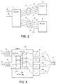
- Figure 2 shows a fragment of a network consisting of three routers, 1-3, and a number of trunks.
- these trunks would be handled as completely separate outputs with each routing table entry specifying a single one of these trunks as a destination.
- no advantage is taken of the fact that these trunks have a common destination.
- these four trunks, 11-14 are treated as a single composite trunk, 10, for purposes of routing,
- the figure also shows two additional trunks attached to router 1, 31 and 32, and a composite trunk, 20, consisting of four trunks, 21-24, that connects router 1 with router 3.
- each trunk in the figure is actually a pair of communication channels, one in each direction.
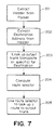
- FIG. 3 A block diagram of a portion of router 1 is shown in Figure 3 .
- the router comprises a routing fabric 100 and line cards, each of which terminates a trunk and serves as a port between the trunk and routing fabric.
- trunks 11-14 are terminated in line cards 41-44.
- the figure shows the preferred embodiment in which the routing fabric is a three-dimensional torus interconnection network.
- the routing fabric is a three-dimensional torus interconnection network.
- One skilled in the art of router design will understand that other fabric topologies such as crossbars, multi-stage networks, and buses can also be used with composite trunking.
- each node of the interconnection network is labeled with a 3-tuple giving its X, Y, and Z coordinates respectively. The figure shows some but not all of these labels.
- Each node is connected to its neighbors in six directions. End around connections, for example connecting (0,0,0) to (0,0,3) are included in the preferred embodiment but are not shown in the figure for clarity.
- the network can be scaled up to a 10x8x5 torus containing 400 nodes.
- Each line card connects to one node of the routing fabric.
- line card 51 for example, connects to fabric node (0,0,3).
- Packets are forwarded between line cards by traversing the links of the router fabric. For example, a packet that arrives on trunk 31 and departs on trunk 41 would most likely be forwarded across the single Y link from (0,0,3) to (0,1,3). However a 3-hop route from (0,0,3) to (1,0,3) (1,1,3) and (0,1,3) is also possible.
- the details of forwarding packets across the routing fabric is described in pending patent application Serial No. 08/918,556, filed August 22, 1997, by William J. Dally, Philip P. Carvey, Larry R. Dennison and P. Alan King.
- each IP (Internet protocol) packet consists of a header and a body.
- the header contains a number of fields that include a packet type, a source IP address and port, and a destination IP address and port.
- the destination IP address is used to determine the output trunk on which the packet should be routed. All five of these fields together are used to identify the packet as belonging to a particular flow of packets. While not strictly required by the IP protocol, it is generally understood that the packets within a given flow must be transmitted in the order in which they arrive. To ensure this, the router assigns packets of the same flow to the same path through the routing fabric and to the same trunk of a composite trunk.
- FIG. 5A shows a prior art routing table in which each destination IP address is associated with a specific output trunk.
- the routing table associates prefixes of destination addresses with output trunks, and the table is searched to find the longest prefix that matches the destination address.
- a route through the fabric router from the input line card to the output line card must still be determined.
- This fabric route is determined by a look up in the fabric forwarding table.
- the fabric forwarding table associates a source trunk, destination trunk pair with a list of possible fabric routes between that source and destination.
- each source node stores only its portion of the table and so the lookup associates a destination trunk with a set of routes.
- the table entry and thus the route to be used is selected from the set of routes by bashing the flow identifier for the packet. This ensures that all packets of the same flow follow the same fabric route and hence remain in order.
- the step of looking up the fabric route from the destination trunk resolves which specific trunk of a composite trunk is to be used for a given packet.
- a packet from flow 0 arriving on trunk 31 destined for composite trunk 10 is assigned a fabric route of +Y.
- this route takes the packet from node (0,0,3), associated with link card 51 and hence trunk 31, in the positive Y direction to node (0,1,3) where the packet exits through line card 41 to trunk 11.
- a second packet from flow 1 arriving on trunk 31 also destined for composite trunk 10 is assigned a fabric route of-Z, +Y, +X. This route takes the packet to node (1,1,2) where it exits via line card 42 to trunk 12.
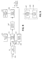
- the process of forwarding an incoming packet is illustrated in the flowchart of Figure 7 .
- the header (see Figure 4 ) is extracted from the packet in box 201 and the destination IP address is extracted from the header in box 202.
- the destination IP address is used to look up the output trunk (composite or specific) in a routing table (see Figure 7 ) in box 203.
- this step involves performing a search of the stored routing table to find the longest matching prefix of the destination address.
- a route selector is computed by extracting the flow identifier from the packet header and hashing this flow identifier, for example using a bitwise exclusive or operation.
- route selector and destination trunk are used to lookup a fabric route in the fabric forwarding table (see Figure 6 ). This fabric route implicitly selects the specific trunk of a composite trunk to be used as the trunk at which the route terminates.
- the forwarding process of Figure 7 is pipelined as shown in Figure 8 .
- the router is able to process packets with a very high throughput by operating on several packets simultaneously.
- Packets arrive on an incoming line 300.
- a line interface 301 recovers data and clock from the incoming line, performs framing, and extracts packets from the incoming data stream.
- the line interface stores the body of each packet in the packet memory 304 and places the header of the packet, along with a pointer to the body, in a packet descriptor that it passes over line 302 to the next stage of processing. Packet descriptors from the line interface are received by the output trunk lookup pipeline stage 305.
- This stage searches a routing table (see Figure 5 ) to find the longest matching prefix of the packet destination.
- the output trunk (composite or specific) associated with the matching prefix is selected as the output for this packet and recorded in the packet descriptor.
- the updated packet descriptor is then forwarded to box 307.
- the source address, destination address, port numbers, and packet type fields are extracted from the packet header and used to form a flow identifier.
- the flow identifier is then hashed by exclusive-oring several 12-bit fields of the identifier with each other to form a route selector.
- the computed route selector is stored in the packet descriptor and it is forwarded to the fabric router.
- a fabric route lookup stage 308 uses the route selector and output trunk stored in the packet descriptor to index a fabric forwarding table (see Figure 6 ) and lookup the route to be used to forward the packet to the output through the switch fabric. Using the pointer stored in the packet descriptor, the packet itself is then retrieved from packet memory and forwarded along with route and packet descriptor to the switch fabric. Once in the switch fabric, the route directs the packet to the appropriate output trunk.
- the fabric forwarding table on each source node has 4096 entries for each destination node. This large number of entries is used to accurately divide traffic among multiple routes and trunks with a minimum of round off error. In effect, a table with 4096 entries gives 12 bits of precision in representing the fraction of traffic directed to each route and trunk. For example, consider a case where traffic to one composite trunk, A, is to be divided over 3 trunks, b,c, and d. If there are a small number of entries in the fabric forwarding table for A, it will not be possible to evenly divide the traffic over the three individual trunks. For example, if there are 8 entries for A, then the best we can do is to allocate 3 entries for b, 3 for c, and 2 for d.
- the steps of determining the specific output trunk of a composite trunk to be used and determining the fabric route to reach that specific output trunk can be performed by two separate table lookups.
- the flow identifier and composite output trunk are used to determine a specific output trunk at 207.
- the fabric route to reach this specific output trunk is selected at 209 through a second forwarding table.
- appropriate setting of the fabric routing table can minimize the number of hops that a packet must travel in the routing fabric.
- Routes to nearby destination trunks can be associated with each source node. For example, in Figure 6 , the first route from line card 51 to composite trunk 10 takes the packet one hop to line card 41 and output trunk 11. The first route from line card 52 to composite trunk 10 takes the packet one hop to line card 43 and output trunk 13.
- a particular source node includes entries to multiple routes for load distribution but weights the number of entries to each route to favor the shortest route. This preferential selection of nearby output trunks for each source node can be performed without concern for reordering flows because flows are local to a single source node.
- the fabric forwarding table can be adjusted to dynamically balance the load across the output trunks.
- the load can be balanced by finding a forwarding table entry that directs packets to the overloaded output trunk and rewriting the route in this entry to direct packets to a more lightly loaded output trunk.
Landscapes
- Engineering & Computer Science (AREA)
- Computer Networks & Wireless Communication (AREA)
- Signal Processing (AREA)
- Data Exchanges In Wide-Area Networks (AREA)
- Cable Accessories (AREA)
- Diaphragms For Electromechanical Transducers (AREA)
- Superconductors And Manufacturing Methods Therefor (AREA)
- Organic Low-Molecular-Weight Compounds And Preparation Thereof (AREA)
Abstract
Description
- Data communication between computer systems for applications such as web browsing, electronic mail, file transfer, and electronic commerce is often performed using a family of protocols known as IP (Internet protocol) or sometimes TCP/IP. As applications that use extensive data communication become more popular, the traffic demands on the backbone IP network are increasing exponentially. It is expected that IP routers with several hundred ports operating with aggregate bandwidth of Terabits per second will be needed over the next few years to sustain growth in backbone demand.
- As illustrated in
Figure 1 , the Internet is arranged as a hierarchy of networks. A typical end-user has aworkstation 22 connected to a local-area network orLAN 24. To allow users on the LAN to access the rest of the Internet, the LAN is connected via a router R to aregional network 26 that is maintained and operated by a Regional Network Provider or RNP. The connection is often made through an Internet Service Provider or ISP. To access other regions, the regional network connects to thebackbone network 28 at a Network Access Point (NAP). The NAPs are usually located only in major cities. - The network is made up of links and routers R. In the network backbone, the links are usually fiber optic communication channels operating using the SONET (synchronous optical network) protocol. SONET links operate at a variety of data rates ranging from OC-3 (155Mb/s) to OC-192 (9.9Gb/s). These links, sometimes called trunks, move data from one point to another, often over considerable distances.
- Routers connect a group of links together and perform two functions:
- forwarding and routing. A data packet arriving on one link of a router is forwarded by sending it out on a different link depending on its eventual destination and the state of the output links. To compute the output link for a given packet, the router participates in a routing protocol where all of the routers on the Internet exchange information about the connectivity of the network and compute routing tables based on this information.
- In recent years the volume of Internet traffic has been quadrupling each year. At the same time, the speed of the optical links that carry this traffic has been increasing at a slower rate, quadrupling every three years. Thus, to keep up with traffic demands, networks have added multiple links or trunks between network access points to scale bandwidth at a rate faster than the increase in individual link bandwidth. These multiple trunks may be transmitted on separate fibers or as separate channels wave-division multiplexed over a single fiber, or both.
- Wavelength-division multiplexing (WDM) is an approach to increasing bandwidth between NAPs by multiplexing several channels on a single fiber. With this approach an existing fiber between two NAPs, which originally carried a single channel, is enabled to handle a number (typically 20) channels of the same rate. To accomplish this, a WDM multiplexer is used to combine several channels by modulating each with a slightly different optical wavelength or color of light. The channels, each at a different wavelength, are then combined into a single optical fiber. At the far end of the fiber, separating out the different, colors of light demultiplexes the channels. Upgrading one or more fibers to WDM results in large numbers of parallel trunks between NAPs.
- Prior art "Multilink PPP: One Big Virtual WAN Pipe", by G.E. Conant, Data communications, vol. 24, no. 13, September 21, 1995, page 85-88, ISSN:0363-6399, discloses routing packets over a WAN using logical pipes consisting of multiple PPP links.
- Such as those described in Art. 54(3) EPC document
EP-1005745-A0 , orWO-9911033-A1 - Earlier routers treat each of the multiple trunks between two NAPs, and hence two routers, as ordinary links. Each trunk is connected to a router port and all traffic is forwarded over a specific trunk. This has two significant disadvanges: the complexity of the routing table is increased, and it becomes difficult to balance load across the trunks. Instead of simply directing all westbound traffic out of New York to Chicago, for example, with prior art routers it is necessary to direct distinct portions of this traffic over each of the N trunks between the two cities. The traffic is divided over these trunks by making a different routing table entry for each portion of traffic to direct it over a particular trunk.
- Earlier routers also have difficulty balancing the load across the set of trunks between two points. Traffic is divided over these trunks by the routing table and hence by destination address. At different points in time, the traffic to a set of destinations mapped to one trunk may be greater than the traffic to the set of destinations mapped to a second trunk leading to load imbalance between the trunks.
- Both of these problems, routing table complexity and load imbalance, increase in magnitude as the number of trunks between a pair of routers increases.
- According to one aspect of the invention there is provided a network router comprising a plurality of trunk ports and a routing fabric of plural nodes for transfer to data packets between trunk input and output ports at respective nodes, paths between input and output ports including multiple hops through nodes of the fabric, characterized by: a composite port of plural output ports to plural trunks which serve as a composite trunk to a common destination; the composite port including ports from said plural nodes; and an output port selector at each input mode which selects an output port for a packet from the composite port.
- Another aspect of the invention provides a method of routing a packet in a network according to
claim 14. - The router of the invention overcomes the limitation of prior art routers by treating all of the links or trunks to a given destination as a single composite trunk. With composite trunking, all of the westbound traffic out of New York, for example, would be directed onto the single composite trunk to Chicago rather than be divided into N separate portions, one for each of the N links to Chicago.
- When a westbound packet arrives at the New York router, the routing table lookup selects the composite trunk to Chicago as the outgoing link for the packet. A separate trunk selection step then picks one of the multiple trunks to Chicago to carry this particular packet and the packet is forwarded to that trunk. The trunk selection is performed to balance load across the trunks while preserving packet ordering within individual flows. It may also be performed to select the 'closest' output port for a given packet.
- The use of composite trunks has three primary advantages. First, it simplifies routing tables by allowing large groups of destinations to be mapped to a single composite output port rather than requiring that many smaller groups be individually mapped to distinct output ports. Second, composite trunking makes it easier to balance load across multiple trunks by allowing load to be dynamically shifted across the individual trunks making up a composite trunk without changing the routing function. Finally, composite trunking can give more efficient use of fabric channels in a direct fabric network by selecting the output trunk that is nearest the packet waiting to be transmitted.
- In accordance with the invention, a network router comprises a plurality of trunk ports, including a composite port of plural ports. Those ports connect to plural trunks which serve as a composite trunk to a common destination. A routing fabric within the router transfers data packets between trunk ports. An output port selector selects an output port for a packet from a composite port. The router identifies a destination of packets, selects one of plural trunks forming a composite trunk to the destination and forwards the packet toward the destination on the selected trunk.
- Preferably, the router maintains ordering of packets within a flow by routing the packets of the flow in a single fabric route within the router and over a single trunk of the composite trunk. The output port selector is able to balance load across the trunks of a composite trunk and may even provide dynamic balancing by changing port selection in response to changes in load. The output port selector may favor output ports having lesser distances to be traversed on the routing fabric from an input port.
- Preferably, the output port selector determines the output port by table lookup. More specifically, a routing table maps destination addresses to composite trunks, and a forwarding table maps composite trunks to sets of routes within the routing fabric.
- The invention is particularly applicable to the Internet where the destination addresses are Internet protocol addresses. The preferred routing fabric is a three dimensional torus.
- The foregoing and other objects, features and advantages of the invention will be apparent from the following more particular description of preferred embodiments of the invention, as illustrated in the accompanying drawings in which like reference characters refer to the same parts throughout the different views. The drawings are not necessarily to scale, emphasis instead being placed upon illustrating the principles of the invention.
-
Figure 1 illustrates the Internet arranged as a hierarchy of networks. -
Figure 2 illustrates a fragment of a network comprising three routers linked through composite trunks. -
Figure 3 illustrates one of the routers ofFigure 2 . -
Figure 4 illustrates an Internet protocol packet. -
Figure 5A illustrates a prior art routing table within an Internet router. -
Figure 5B illustrates a routing table within an Internet router embodying the present invention. -
Figure 6 illustrates a fabric forwarding table used in one embodiment of the invention. -
Figure 7 is a flow chart of the routing process. -
Figure 8 illustrates the hardware pipeline used to process the method ofFigure 7 . -
Figure 9 illustrates the route selection step ofFigure 7 in an alternative embodiment of the invention. -
Figure 2 shows a fragment of a network consisting of three routers, 1-3, and a number of trunks. There are four trunks, 11-14, that connect router 1 torouter 2. In a prior art router, these trunks would be handled as completely separate outputs with each routing table entry specifying a single one of these trunks as a destination. In such prior art routers, no advantage is taken of the fact that these trunks have a common destination. In the present router, however, these four trunks, 11-14, are treated as a single composite trunk, 10, for purposes of routing, The figure also shows two additional trunks attached torouter router 3. In common practice, each trunk in the figure is actually a pair of communication channels, one in each direction. - A block diagram of a portion of router 1 is shown in
Figure 3 . As shown, the router comprises arouting fabric 100 and line cards, each of which terminates a trunk and serves as a port between the trunk and routing fabric. For example, trunks 11-14 are terminated in line cards 41-44. The figure shows the preferred embodiment in which the routing fabric is a three-dimensional torus interconnection network. One skilled in the art of router design will understand that other fabric topologies such as crossbars, multi-stage networks, and buses can also be used with composite trunking. - In the preferred embodiment each node of the interconnection network is labeled with a 3-tuple giving its X, Y, and Z coordinates respectively. The figure shows some but not all of these labels. Each node is connected to its neighbors in six directions. End around connections, for example connecting (0,0,0) to (0,0,3) are included in the preferred embodiment but are not shown in the figure for clarity. In the preferred embodiment, the network can be scaled up to a 10x8x5 torus containing 400 nodes. Each line card connects to one node of the routing fabric. In
Figure 3 ,line card 51, for example, connects to fabric node (0,0,3). - Packets are forwarded between line cards by traversing the links of the router fabric. For example, a packet that arrives on
trunk 31 and departs ontrunk 41 would most likely be forwarded across the single Y link from (0,0,3) to (0,1,3). However a 3-hop route from (0,0,3) to (1,0,3) (1,1,3) and (0,1,3) is also possible. The details of forwarding packets across the routing fabric is described in pending patent application Serial No. 08/918,556, filed August 22, 1997, by William J. Dally, Philip P. Carvey, Larry R. Dennison and P. Alan King. - As shown in
Figure 4 , each IP (Internet protocol) packet consists of a header and a body. The header contains a number of fields that include a packet type, a source IP address and port, and a destination IP address and port. The destination IP address is used to determine the output trunk on which the packet should be routed. All five of these fields together are used to identify the packet as belonging to a particular flow of packets. While not strictly required by the IP protocol, it is generally understood that the packets within a given flow must be transmitted in the order in which they arrive. To ensure this, the router assigns packets of the same flow to the same path through the routing fabric and to the same trunk of a composite trunk. - When a packet arrives at a router, the destination IP address of the packet is used to look up the output port to be used by the packet in a routing table.
Figure 5A shows a prior art routing table in which each destination IP address is associated with a specific output trunk. A method used in the router of this invention, in which a destination IP address may be associated with either a specific port and output trunk or a composite output port and trunk, is shown inFigure 5B . In general, the routing table associates prefixes of destination addresses with output trunks, and the table is searched to find the longest prefix that matches the destination address. See Doeringer, Karjoth and Hassehi, "Routing on Longest-Matching Prefixes," IEEE/ACM Transactions on Networking, 1(4), February 1996, pp. 86-07. One organization of these routing tables and a method used to search for the longest matching prefix is described in pending provisional patent application entitled "Application and Method for Efficient Prefix Search" by Gregory Waters, Larry Dennison, Phillip Carvey and William J. Dally, filed on May 5, 1998, (Attorney Docket No. AVI97-05p). - After a packet has been assigned an output trunk, individual or composite, a route through the fabric router from the input line card to the output line card must still be determined. This fabric route is determined by a look up in the fabric forwarding table. As shown in
Figure 6 , the fabric forwarding table associates a source trunk, destination trunk pair with a list of possible fabric routes between that source and destination. In practice, each source node stores only its portion of the table and so the lookup associates a destination trunk with a set of routes. In the preferred embodiment, the table entry and thus the route to be used is selected from the set of routes by bashing the flow identifier for the packet. This ensures that all packets of the same flow follow the same fabric route and hence remain in order. - In that preferred embodiment, the step of looking up the fabric route from the destination trunk resolves which specific trunk of a composite trunk is to be used for a given packet. With the fabric forwarding table of
Figure 6 , for example, a packet from flow 0 arriving ontrunk 31 destined forcomposite trunk 10 is assigned a fabric route of +Y. Referring toFigure 3 , this route takes the packet from node (0,0,3), associated withlink card 51 and hencetrunk 31, in the positive Y direction to node (0,1,3) where the packet exits throughline card 41 to trunk 11. A second packet from flow 1 arriving ontrunk 31 also destined forcomposite trunk 10 is assigned a fabric route of-Z, +Y, +X. This route takes the packet to node (1,1,2) where it exits vialine card 42 totrunk 12. By distributing the fabric routes across the individual trunks comprising the composite trunk, traffic is distributed evenly across the composite trunk and thus statically balanced. - The process of forwarding an incoming packet is illustrated in the flowchart of
Figure 7 . To start the processing, the header (seeFigure 4 ) is extracted from the packet inbox 201 and the destination IP address is extracted from the header inbox 202. Next, the destination IP address is used to look up the output trunk (composite or specific) in a routing table (seeFigure 7 ) inbox 203. In the preferred embodiment, this step involves performing a search of the stored routing table to find the longest matching prefix of the destination address. In box 204 a route selector is computed by extracting the flow identifier from the packet header and hashing this flow identifier, for example using a bitwise exclusive or operation. As described below, a relatively large route selector (12 bits) is used in the preferred embodiment to avoid excessive roundoff error in the division of traffic among routes and trunks. Finally, inbox 205, the route selector and destination trunk are used to lookup a fabric route in the fabric forwarding table (seeFigure 6 ). This fabric route implicitly selects the specific trunk of a composite trunk to be used as the trunk at which the route terminates. - In the preferred embodiment, the forwarding process of
Figure 7 is pipelined as shown inFigure 8 . By pipelining the process, the router is able to process packets with a very high throughput by operating on several packets simultaneously. Packets arrive on anincoming line 300. For example this might be an OC-48c SONET line. Aline interface 301 recovers data and clock from the incoming line, performs framing, and extracts packets from the incoming data stream. The line interface stores the body of each packet in thepacket memory 304 and places the header of the packet, along with a pointer to the body, in a packet descriptor that it passes overline 302 to the next stage of processing. Packet descriptors from the line interface are received by the output trunklookup pipeline stage 305. This stage searches a routing table (seeFigure 5 ) to find the longest matching prefix of the packet destination. The output trunk (composite or specific) associated with the matching prefix is selected as the output for this packet and recorded in the packet descriptor. The updated packet descriptor is then forwarded tobox 307. In this stage, the source address, destination address, port numbers, and packet type fields are extracted from the packet header and used to form a flow identifier. The flow identifier is then hashed by exclusive-oring several 12-bit fields of the identifier with each other to form a route selector. The computed route selector is stored in the packet descriptor and it is forwarded to the fabric router. Within the fabric router, a fabricroute lookup stage 308 uses the route selector and output trunk stored in the packet descriptor to index a fabric forwarding table (seeFigure 6 ) and lookup the route to be used to forward the packet to the output through the switch fabric. Using the pointer stored in the packet descriptor, the packet itself is then retrieved from packet memory and forwarded along with route and packet descriptor to the switch fabric. Once in the switch fabric, the route directs the packet to the appropriate output trunk. - In the preferred embodiment, the fabric forwarding table on each source node has 4096 entries for each destination node. This large number of entries is used to accurately divide traffic among multiple routes and trunks with a minimum of round off error. In effect, a table with 4096 entries gives 12 bits of precision in representing the fraction of traffic directed to each route and trunk. For example, consider a case where traffic to one composite trunk, A, is to be divided over 3 trunks, b,c, and d. If there are a small number of entries in the fabric forwarding table for A, it will not be possible to evenly divide the traffic over the three individual trunks. For example, if there are 8 entries for A, then the best we can do is to allocate 3 entries for b, 3 for c, and 2 for d. This gives a large imbalance (50%) between c and d due to the limited precision (3 bits) used to represent the fraction 1/3. On the other hand, with 4096 entries, the assignment can be 1365 entries for b and c, and 1366 entries for d, an imbalance of less than 0.1%.
- In an alternative embodiment of
Figure 9 , the steps of determining the specific output trunk of a composite trunk to be used and determining the fabric route to reach that specific output trunk can be performed by two separate table lookups. The flow identifier and composite output trunk are used to determine a specific output trunk at 207. Finally, the fabric route to reach this specific output trunk is selected at 209 through a second forwarding table. - In either embodiment, appropriate setting of the fabric routing table can minimize the number of hops that a packet must travel in the routing fabric. Routes to nearby destination trunks can be associated with each source node. For example, in
Figure 6 , the first route fromline card 51 tocomposite trunk 10 takes the packet one hop toline card 41 and output trunk 11. The first route fromline card 52 tocomposite trunk 10 takes the packet one hop toline card 43 andoutput trunk 13. A particular source node includes entries to multiple routes for load distribution but weights the number of entries to each route to favor the shortest route. This preferential selection of nearby output trunks for each source node can be performed without concern for reordering flows because flows are local to a single source node. - If one output trunk of a composite trunk becomes a bottleneck, the fabric forwarding table can be adjusted to dynamically balance the load across the output trunks. The load can be balanced by finding a forwarding table entry that directs packets to the overloaded output trunk and rewriting the route in this entry to direct packets to a more lightly loaded output trunk. By adjusting routes, and hence the distribution of flows, one at a time, the load incrementally approaches perfect balance across the output trunks. Each adjustment may momentarily reorder packets within the adjusted flows. However, after the adjustment is complete ordering will again be preserved.
- While this invention has been particularly shown and described with references to preferred embodiments thereof, it will be understood by those skilled in the art that various changes in form and details may be made therein without departing from the scope of the invention as defined by the appended claims. Those skilled in the art will recognize or be able to ascertain using no more than routine experimentation, many equivalents to the specific embodiments of the invention described specifically herein.
Claims (25)
- A network router comprising a plurality of trunk ports and a routing fabric (100) of plural nodes for transfer of data packets between trunk input and output ports at respective nodes, paths between input and output ports including multiple hops through nodes of the fabric, characterized by:a composite port (10,20) of plural output ports (41,42) to plural trunks (11,12) which serve as a composite trunk (10) to a common destination;the composite port including ports from said plural nodes; andan output port selector at each input node which selects an output port for a packet from the composite port.
- The router as claimed in claim 1 wherein the output port selector maintains ordering of packets within a flow by routing the packets of the flow on a single trunk (11) of the composite trunk (10).
- The router as claimed in claim 2 wherein the output port selector further maintains ordering of packets within the flow by routing the packets of the flow along a single route through the router fabric (100).
- The router as claimed in claim 1 wherein the output port selector balances load across the trunks (11, 12) of the composite trunk (10).
- The router as claimed in claim 1 wherein the output port selector dynamically balances load across the trunks (11,12) of the composite trunk (10).
- The router as claimed in claim 1 wherein the output port selector favors output ports (41,42) having lesser distances to be traversed on the routing fabric (100) from an input port.
- The router as claimed in claim 1 wherein the output port selector determines the output port within the composite port (10,20) by table lookup.
- The router as claimed in claim 1 wherein the output port selector comprises a routing table which maps destination addresses to composite trunks (10,20).
- The router as claimed in claim 8 wherein the output port selector further comprises a forwarding table which maps composite trunks (10,20) to sets of routes within the routing fabric (100).
- The router as claimed in claim 9 wherein the network is the Internet and the destination addresses are Internet protocol addresses.
- The router as claimed in claim 10 wherein the routing fabric (100) is a three-dimensional torus.
- The router as claimed in claim 8 wherein the output port selector further comprises a forwarding table which maps composite trunks (10,20) to sets of output ports (41,42).
- The router as claimed in claim 12 wherein the output port selector further comprises a forwarding table which maps output ports (41,42) to sets of routes within the routing fabric (100).
- A method of routing a packet in a network comprising, when a packet arrives at a router, identifying a destination of the packet, selecting a trunk to the destination, and forwarding the packet through the routing fabric on a path including multiple hops through nodes of the fabric toward the destination on the selected trunk, characterized by:plural trunks (11, 12) forming a composite trunk to the destination, the trunks of the composite trunk connecting to plural nodes of the routing fabric (100) of the router; andthe selected trunk to the destination being selected from one of the plural trunks of the composite trunk to the destination.
- The method as claimed in claim 14 wherein the trunk is selected to maintain ordering of packets within a flow by routing the packets of the flow on a single trunk of the composite trunk (10).
- The method as claimed in claim 15 wherein routing within the routing fabric (100) is selected to maintain order of the packets within the flow by routing the packets of the flow along a single route.
- The method as claimed in claim 14 wherein the trunk is selected to balance load across the trunks (11,12) of the composite trunk (10).
- The method as claimed in claim 14 wherein the trunk is selected to dynamically balance load across the trunks (11,12) of the composite trunk (10).
- The method as claimed in claim 14 wherein the trunk is selected to favor a lesser distance between input and output ports (41,42) on the routing fabric (100).
- The method as claimed in claim 14 wherein the trunk is selected by table lookup.
- The method as claimed in claim 14 wherein the step of selecting one of plural trunks (11,12) includes the step of determining the composite trunk (10) from a destination address through routing table lookup.
- The method as claimed in claim 21 wherein the step of selecting one of plural trunks (11, 12) further comprises selecting a route within the routing fabric (100) through a forwarding table lookup.
- The method as claimed in claim 14 wherein the destination is identified from a final destination identifier included in the packet.
- The method as claimed in claim 23 wherein the network is the Internet and the packet is routed under an Internet protocol
- The method as claimed in claim 24 wherein the packet is routed within the routing fabric (100) on a three-dimensional torus fabric from an input port to an output port.
Applications Claiming Priority (5)
| Application Number | Priority Date | Filing Date | Title |
|---|---|---|---|
| US8292398P | 1998-04-24 | 1998-04-24 | |
| US82923P | 1998-04-24 | ||
| US09/073,842 US6359879B1 (en) | 1998-04-24 | 1998-05-06 | Composite trunking |
| PCT/US1999/008334 WO1999056432A2 (en) | 1998-04-24 | 1999-04-15 | Composite trunking in a router |
| US73842 | 2002-02-11 |
Publications (2)
| Publication Number | Publication Date |
|---|---|
| EP1070413A2 EP1070413A2 (en) | 2001-01-24 |
| EP1070413B1 true EP1070413B1 (en) | 2008-02-27 |
Family
ID=26754950
Family Applications (1)
| Application Number | Title | Priority Date | Filing Date |
|---|---|---|---|
| EP99917557A Expired - Lifetime EP1070413B1 (en) | 1998-04-24 | 1999-04-15 | Composite trunking in a router |
Country Status (9)
| Country | Link |
|---|---|
| US (2) | US6359879B1 (en) |
| EP (1) | EP1070413B1 (en) |
| JP (1) | JP2002513244A (en) |
| KR (1) | KR100655012B1 (en) |
| AT (1) | ATE387789T1 (en) |
| AU (1) | AU3564999A (en) |
| CA (1) | CA2329481C (en) |
| DE (1) | DE69938239T2 (en) |
| WO (1) | WO1999056432A2 (en) |
Families Citing this family (65)
| Publication number | Priority date | Publication date | Assignee | Title |
|---|---|---|---|---|
| US6359879B1 (en) * | 1998-04-24 | 2002-03-19 | Avici Systems | Composite trunking |
| US6665702B1 (en) | 1998-07-15 | 2003-12-16 | Radware Ltd. | Load balancing |
| US6952401B1 (en) * | 1999-03-17 | 2005-10-04 | Broadcom Corporation | Method for load balancing in a network switch |
| GB2348570B (en) * | 1999-03-31 | 2003-03-05 | Ericsson Telefon Ab L M | Mobile internet access |
| US6658015B1 (en) * | 1999-05-28 | 2003-12-02 | Advanced Micro Devices, Inc. | Multiport switch with plurality of logic engines for simultaneously processing different respective data frames |
| US6901517B1 (en) * | 1999-07-16 | 2005-05-31 | Marconi Communications, Inc. | Hardware based security groups, firewall load sharing, and firewall redundancy |
| GB2359692B (en) * | 2000-02-26 | 2003-06-25 | 3Com Corp | Stackable network unit including registers for identifying stack members and trunk ports |
| US6765866B1 (en) | 2000-02-29 | 2004-07-20 | Mosaid Technologies, Inc. | Link aggregation |
| US7688727B1 (en) | 2000-04-17 | 2010-03-30 | Juniper Networks, Inc. | Filtering and route lookup in a switching device |
| US7215637B1 (en) | 2000-04-17 | 2007-05-08 | Juniper Networks, Inc. | Systems and methods for processing packets |
| US6798777B1 (en) | 2000-04-17 | 2004-09-28 | Juniper Networks, Inc. | Filtering and route lookup in a switching device |
| US7123620B1 (en) * | 2000-04-25 | 2006-10-17 | Cisco Technology, Inc. | Apparatus and method for scalable and dynamic traffic engineering in a data communication network |
| US6385209B1 (en) * | 2000-06-14 | 2002-05-07 | Pluris, Inc. | Method and apparatus for mapping data packets between lines of differing capacity at a router interface |
| EP1168710B1 (en) * | 2000-06-19 | 2005-11-23 | Broadcom Corporation | Method and device for frame forwarding in a switch fabric |
| US7596139B2 (en) | 2000-11-17 | 2009-09-29 | Foundry Networks, Inc. | Backplane interface adapter with error control and redundant fabric |
| US7218632B1 (en) * | 2000-12-06 | 2007-05-15 | Cisco Technology, Inc. | Packet processing engine architecture |
| US20020078226A1 (en) * | 2000-12-15 | 2002-06-20 | Kei Kato | Datagram transmission device |
| US20030141093A1 (en) * | 2000-12-21 | 2003-07-31 | Jacob Tirosh | System and method for routing a media stream |
| JP2002217950A (en) * | 2001-01-15 | 2002-08-02 | Sony Corp | Information processor and method, storage medium and program |
| US8520679B1 (en) * | 2001-01-24 | 2013-08-27 | Advanced Medical Devices, Inc. | Trunking distribution systems and methods |
| US6909695B2 (en) * | 2001-05-07 | 2005-06-21 | Sun Microsystems, Inc. | Fault-tolerant, self-healing routing scheme for a multi-path interconnection fabric in a storage network |
| US7519735B1 (en) * | 2001-05-08 | 2009-04-14 | Juniper Networks, Inc. | Single board routing arrangement |
| US7102996B1 (en) | 2001-05-24 | 2006-09-05 | F5 Networks, Inc. | Method and system for scaling network traffic managers |
| US8004971B1 (en) | 2001-05-24 | 2011-08-23 | F5 Networks, Inc. | Method and system for scaling network traffic managers using connection keys |
| US7290059B2 (en) * | 2001-08-13 | 2007-10-30 | Intel Corporation | Apparatus and method for scalable server load balancing |
| US7787370B1 (en) * | 2001-09-06 | 2010-08-31 | Nortel Networks Limited | Technique for adaptively load balancing connections in multi-link trunks |
| US7813346B1 (en) | 2001-11-21 | 2010-10-12 | Juniper Networks, Inc. | Filter-based forwarding in a network |
| US7313135B2 (en) | 2002-01-31 | 2007-12-25 | Mosaid Technologies, Inc. | Trunking in a matrix |
| EP1337078B1 (en) * | 2002-02-13 | 2009-05-06 | Alcatel Canada Inc. | Trunk groups selection in a communication network based on load balance |
| CA2371654A1 (en) | 2002-02-13 | 2003-08-13 | Alcatel Canada Inc. | System and method for parallel connection selection in a communication network |
| US20120155466A1 (en) * | 2002-05-06 | 2012-06-21 | Ian Edward Davis | Method and apparatus for efficiently processing data packets in a computer network |
| US7649885B1 (en) * | 2002-05-06 | 2010-01-19 | Foundry Networks, Inc. | Network routing system for enhanced efficiency and monitoring capability |
| US7468975B1 (en) * | 2002-05-06 | 2008-12-23 | Foundry Networks, Inc. | Flexible method for processing data packets in a network routing system for enhanced efficiency and monitoring capability |
| US7187687B1 (en) | 2002-05-06 | 2007-03-06 | Foundry Networks, Inc. | Pipeline method and system for switching packets |
| GB0215505D0 (en) * | 2002-07-04 | 2002-08-14 | Univ Cambridge Tech | Packet routing |
| US7554914B1 (en) * | 2002-07-10 | 2009-06-30 | Cisco Technology, Inc. | System and method for adaptively balancing network traffic over router output ports |
| US7039018B2 (en) * | 2002-07-17 | 2006-05-02 | Intel Corporation | Technique to improve network routing using best-match and exact-match techniques |
| US7493412B2 (en) * | 2002-09-12 | 2009-02-17 | International Business Machines Corporation | Method for processing a data packet |
| GB0226249D0 (en) * | 2002-11-11 | 2002-12-18 | Clearspeed Technology Ltd | Traffic handling system |
| US20040177157A1 (en) * | 2003-02-13 | 2004-09-09 | Nortel Networks Limited | Logical grouping of VPN tunnels |
| US6901072B1 (en) | 2003-05-15 | 2005-05-31 | Foundry Networks, Inc. | System and method for high speed packet transmission implementing dual transmit and receive pipelines |
| WO2004112322A1 (en) * | 2003-06-18 | 2004-12-23 | Siemens Aktiengesellschaft | Method for the use of parallel links in packet-oriented networks with multipath routing |
| US20050047440A1 (en) * | 2003-08-25 | 2005-03-03 | Jerome Plun | Division of data structures for efficient simulation |
| US7852836B2 (en) * | 2003-11-19 | 2010-12-14 | Cray Inc. | Reduced arbitration routing system and method |
| US7817659B2 (en) * | 2004-03-26 | 2010-10-19 | Foundry Networks, Llc | Method and apparatus for aggregating input data streams |
| US8730961B1 (en) | 2004-04-26 | 2014-05-20 | Foundry Networks, Llc | System and method for optimizing router lookup |
| US20050265308A1 (en) * | 2004-05-07 | 2005-12-01 | Abdulkadev Barbir | Selection techniques for logical grouping of VPN tunnels |
| US8660112B2 (en) * | 2004-12-27 | 2014-02-25 | Telefonaktiebolaget L M Ericsson (Publ) | Adaptive router architecture using logical internal addressing |
| US8448162B2 (en) * | 2005-12-28 | 2013-05-21 | Foundry Networks, Llc | Hitless software upgrades |
| US7903654B2 (en) * | 2006-08-22 | 2011-03-08 | Foundry Networks, Llc | System and method for ECMP load sharing |
| US8238255B2 (en) * | 2006-11-22 | 2012-08-07 | Foundry Networks, Llc | Recovering from failures without impact on data traffic in a shared bus architecture |
| US7978614B2 (en) | 2007-01-11 | 2011-07-12 | Foundry Network, LLC | Techniques for detecting non-receipt of fault detection protocol packets |
| US9344356B2 (en) * | 2007-02-28 | 2016-05-17 | Hewlett Packard Enterprise Development Lp | Transmitting a packet from a distributed trunk switch |
| US20080205376A1 (en) * | 2007-02-28 | 2008-08-28 | Michael Patmon | Redundant router having load sharing functionality |
| US8271859B2 (en) * | 2007-07-18 | 2012-09-18 | Foundry Networks Llc | Segmented CRC design in high speed networks |
| FI20075578A0 (en) * | 2007-08-17 | 2007-08-17 | Nokia Siemens Networks Oy | Packet switching in telecommunications networks |
| US8509236B2 (en) * | 2007-09-26 | 2013-08-13 | Foundry Networks, Llc | Techniques for selecting paths and/or trunk ports for forwarding traffic flows |
| US8154998B2 (en) * | 2008-08-11 | 2012-04-10 | At&T Intellectual Property I, L.P. | Method and apparatus for resizing a trunk in a network |
| US8090901B2 (en) * | 2009-05-14 | 2012-01-03 | Brocade Communications Systems, Inc. | TCAM management approach that minimize movements |
| TWI403195B (en) * | 2009-09-16 | 2013-07-21 | Ralink Technology Corp | Method for wireless lan link aggregation and system for using the same |
| US8599850B2 (en) | 2009-09-21 | 2013-12-03 | Brocade Communications Systems, Inc. | Provisioning single or multistage networks using ethernet service instances (ESIs) |
| US11777809B2 (en) | 2010-05-11 | 2023-10-03 | Comcast Cable Communications, Llc | Dynamic assignment of signals to ports in an access platform |
| US9307304B2 (en) * | 2010-05-11 | 2016-04-05 | Comcast Cable Communications, Llc | Dynamic assignment of signals to ports in an access platform |
| US8391174B2 (en) * | 2010-07-13 | 2013-03-05 | Hewlett-Packard Development Company, L.P. | Data packet routing |
| US20160283828A1 (en) * | 2015-03-27 | 2016-09-29 | Kyocera Document Solutions Inc. | Automated Print Job Redirection |
Citations (1)
| Publication number | Priority date | Publication date | Assignee | Title |
|---|---|---|---|---|
| EP1005745A1 (en) * | 1997-08-22 | 2000-06-07 | Avici Systems | Router with virtual channel allocation |
Family Cites Families (83)
| Publication number | Priority date | Publication date | Assignee | Title |
|---|---|---|---|---|
| US4340775A (en) * | 1980-10-29 | 1982-07-20 | Siemens Corporation | Apparatus and method for controlling a modular telecommunication system |
| JPH0614644B2 (en) | 1984-04-05 | 1994-02-23 | 日本電信電話株式会社 | Packet switching trunk line selection method |
| US5021949A (en) * | 1988-02-29 | 1991-06-04 | International Business Machines Corporation | Method and apparatus for linking an SNA host to a remote SNA host over a packet switched communications network |
| US4829563A (en) * | 1988-04-07 | 1989-05-09 | Teknekron Infoswitch Corporation | Method for predictive dialing |
| US5115495A (en) * | 1988-10-18 | 1992-05-19 | The Mitre Corporation | Communications network system using full-juncture and partial-juncture station status information for alternate-path distance-vector routing |
| US5095480A (en) * | 1989-06-16 | 1992-03-10 | Fenner Peter R | Message routing system for shared communication media networks |
| US5860136A (en) * | 1989-06-16 | 1999-01-12 | Fenner; Peter R. | Method and apparatus for use of associated memory with large key spaces |
| AU647086B2 (en) * | 1990-01-30 | 1994-03-17 | Johnson Service Company | Networked facilities management system |
| US5155594A (en) * | 1990-05-11 | 1992-10-13 | Picturetel Corporation | Hierarchical encoding method and apparatus employing background references for efficiently communicating image sequences |
| US5265257A (en) | 1990-06-22 | 1993-11-23 | Digital Equipment Corporation | Fast arbiter having easy scaling for large numbers of requesters, large numbers of resource types with multiple instances of each type, and selectable queuing disciplines |
| US5748619A (en) * | 1991-10-01 | 1998-05-05 | Meier; Robert C. | Communication network providing wireless and hard-wired dynamic routing |
| SE470039B (en) * | 1992-03-17 | 1993-10-25 | Ellemtel Utvecklings Ab | Ways to achieve link grouping in a packet selector |
| US5233604A (en) * | 1992-04-28 | 1993-08-03 | International Business Machines Corporation | Methods and apparatus for optimum path selection in packet transmission networks |
| JPH066362A (en) | 1992-06-23 | 1994-01-14 | Hitachi Ltd | Message processing load distribution system for host system in lan |
| US5365524A (en) * | 1992-11-06 | 1994-11-15 | At&T Bell Laboratories | Establishing telecommunications call paths between clustered switching entities |
| JPH07118717B2 (en) * | 1993-01-05 | 1995-12-18 | 日本電気株式会社 | Multi-protocol packet network configuration method |
| FR2703545B1 (en) * | 1993-03-31 | 1995-05-12 | Alcatel Nv | Asynchronous switching node dynamically distributing cells to outputs constituting a so-called irregular group. |
| US5347511A (en) * | 1993-06-07 | 1994-09-13 | International Business Machines Corp. | Traffic management in packet communications networks |
| US5905723A (en) | 1993-06-23 | 1999-05-18 | Cabletron Systems, Inc. | System for achieving scalable router performance |
| US5631897A (en) | 1993-10-01 | 1997-05-20 | Nec America, Inc. | Apparatus and method for incorporating a large number of destinations over circuit-switched wide area network connections |
| US5412653A (en) | 1993-10-15 | 1995-05-02 | International Business Machines Corporation | Dynamic switch cascading system |
| JP3084066B2 (en) * | 1993-12-24 | 2000-09-04 | インターナシヨナル・ビジネス・マシーンズ・コーポレーシヨン | Routing bandwidth reservation connections in information networks |
| US5526414A (en) * | 1994-10-26 | 1996-06-11 | Northern Telecom Limited | Dynamically controlled routing using virtual nodes |
| US6324179B1 (en) * | 1994-12-21 | 2001-11-27 | Lucent Technologies Inc. | ATM network arranged to interface with STM in-band signaling |
| US5717862A (en) * | 1995-04-27 | 1998-02-10 | International Business Machines Corporation | Method and system for message status reporting in a multi-node network |
| US6097882A (en) * | 1995-06-30 | 2000-08-01 | Digital Equipment Corporation | Method and apparatus of improving network performance and network availability in a client-server network by transparently replicating a network service |
| MX9800791A (en) | 1995-07-28 | 1998-04-30 | British Telecomm | Packet routing. |
| KR100189847B1 (en) * | 1995-10-05 | 1999-06-01 | 이형도 | Catalyst for purifying exhaust gases of automobiles |
| US6011804A (en) * | 1995-12-20 | 2000-01-04 | International Business Machines Corporation | Dynamic bandwidth reservation for control traffic in high speed packet switching networks |
| US5689505A (en) * | 1996-01-16 | 1997-11-18 | Lucent Technologies Inc. | Buffering of multicast cells in switching networks |
| US5781549A (en) * | 1996-02-23 | 1998-07-14 | Allied Telesyn International Corp. | Method and apparatus for switching data packets in a data network |
| US6032266A (en) * | 1996-04-05 | 2000-02-29 | Hitachi, Ltd. | Network system having function of changing route upon failure |
| JP3112827B2 (en) | 1996-04-23 | 2000-11-27 | 日本電気エンジニアリング株式会社 | Packet switching relay system |
| US5878043A (en) * | 1996-05-09 | 1999-03-02 | Northern Telecom Limited | ATM LAN emulation |
| US5918021A (en) * | 1996-06-03 | 1999-06-29 | Intel Corporation | System and method for dynamic distribution of data packets through multiple channels |
| US5841775A (en) | 1996-07-16 | 1998-11-24 | Huang; Alan | Scalable switching network |
| US5881050A (en) * | 1996-07-23 | 1999-03-09 | International Business Machines Corporation | Method and system for non-disruptively assigning link bandwidth to a user in a high speed digital network |
| US6073176A (en) * | 1996-07-29 | 2000-06-06 | Cisco Technology, Inc. | Dynamic bidding protocol for conducting multilink sessions through different physical termination points |
| US5918017A (en) * | 1996-08-23 | 1999-06-29 | Internatioinal Business Machines Corp. | System and method for providing dynamically alterable computer clusters for message routing |
| US5889989A (en) * | 1996-09-16 | 1999-03-30 | The Research Foundation Of State University Of New York | Load sharing controller for optimizing monetary cost |
| US5848055A (en) * | 1996-11-19 | 1998-12-08 | Northern Telecom Limited | Bandwidth correlation means for paths in connection-oriented packet switching networks |
| US6044080A (en) | 1996-11-19 | 2000-03-28 | Pluris, Inc. | Scalable parallel packet router |
| US6104701A (en) * | 1996-12-13 | 2000-08-15 | International Business Machines Corporation | Method and system for performing a least cost routing function for data communications between end users in a multi-network environment |
| US6665733B1 (en) * | 1996-12-30 | 2003-12-16 | Hewlett-Packard Development Company, L.P. | Network communication device including bonded ports for increased bandwidth |
| US5838769A (en) * | 1996-12-31 | 1998-11-17 | Mci Communications Corporation | Method of reducing risk that calls are blocked by egress switch or trunk failures |
| US6052718A (en) * | 1997-01-07 | 2000-04-18 | Sightpath, Inc | Replica routing |
| JP3603524B2 (en) * | 1997-02-05 | 2004-12-22 | 株式会社日立製作所 | Networking method |
| US6591303B1 (en) | 1997-03-07 | 2003-07-08 | Sun Microsystems, Inc. | Method and apparatus for parallel trunking of interfaces to increase transfer bandwidth |
| US6470389B1 (en) * | 1997-03-14 | 2002-10-22 | Lucent Technologies Inc. | Hosting a network service on a cluster of servers using a single-address image |
| US5978463A (en) * | 1997-04-18 | 1999-11-02 | Mci Worldcom, Inc. | Reservation scheduling system for audio conferencing resources |
| US5983281A (en) * | 1997-04-24 | 1999-11-09 | International Business Machines Corporation | Load balancing in a multiple network environment |
| US5949788A (en) * | 1997-05-06 | 1999-09-07 | 3Com Corporation | Method and apparatus for multipoint trunking |
| US6016310A (en) * | 1997-06-30 | 2000-01-18 | Sun Microsystems, Inc. | Trunking support in a high performance network device |
| US6049528A (en) * | 1997-06-30 | 2000-04-11 | Sun Microsystems, Inc. | Trunking ethernet-compatible networks |
| US6393483B1 (en) * | 1997-06-30 | 2002-05-21 | Adaptec, Inc. | Method and apparatus for network interface card load balancing and port aggregation |
| US6151297A (en) * | 1997-07-08 | 2000-11-21 | Hewlett-Packard Company | Method and system for link level server/switch trunking |
| US6192049B1 (en) * | 1997-07-15 | 2001-02-20 | Lucent Technologies Inc. | Jitterless and lossless switching fabric with network routing |
| US6195354B1 (en) * | 1997-07-16 | 2001-02-27 | Nortel Networks Limited | Route selection for path balancing in connection-oriented packet switching networks |
| US6160818A (en) * | 1997-07-17 | 2000-12-12 | At &T Corp | Traffic management in packet communication networks having service priorities and employing effective bandwidths |
| US5959968A (en) * | 1997-07-30 | 1999-09-28 | Cisco Systems, Inc. | Port aggregation protocol |
| US6072797A (en) * | 1997-07-31 | 2000-06-06 | International Business Machines Corporation | Methods, apparatus and computer program products for aggregated transmission groups in high speed networks |
| US6098107A (en) * | 1997-10-31 | 2000-08-01 | Lucent Technologies Inc. | Dynamic algorithms for shortest path tree computation |
| US6434612B1 (en) * | 1997-12-10 | 2002-08-13 | Cisco Technology, Inc. | Connection control interface for asynchronous transfer mode switches |
| US6601084B1 (en) * | 1997-12-19 | 2003-07-29 | Avaya Technology Corp. | Dynamic load balancer for multiple network servers |
| US6233245B1 (en) * | 1997-12-24 | 2001-05-15 | Nortel Networks Limited | Method and apparatus for management of bandwidth in a data communication network |
| US6032194A (en) * | 1997-12-24 | 2000-02-29 | Cisco Technology, Inc. | Method and apparatus for rapidly reconfiguring computer networks |
| US6363077B1 (en) * | 1998-02-13 | 2002-03-26 | Broadcom Corporation | Load balancing in link aggregation and trunking |
| US7411916B2 (en) * | 1998-02-26 | 2008-08-12 | Nortel Networks Limited | Data forwarding method and apparatus |
| US6359879B1 (en) | 1998-04-24 | 2002-03-19 | Avici Systems | Composite trunking |
| US6580715B1 (en) * | 1998-05-04 | 2003-06-17 | Hewlett-Packard Development Company, L.P. | Load balancing switch protocols |
| US6496502B1 (en) * | 1998-06-29 | 2002-12-17 | Nortel Networks Limited | Distributed multi-link trunking method and apparatus |
| US6473791B1 (en) * | 1998-08-17 | 2002-10-29 | Microsoft Corporation | Object load balancing |
| US6587431B1 (en) * | 1998-12-18 | 2003-07-01 | Nortel Networks Limited | Supertrunking for packet switching |
| US6765866B1 (en) * | 2000-02-29 | 2004-07-20 | Mosaid Technologies, Inc. | Link aggregation |
| US7123620B1 (en) * | 2000-04-25 | 2006-10-17 | Cisco Technology, Inc. | Apparatus and method for scalable and dynamic traffic engineering in a data communication network |
| US6950848B1 (en) * | 2000-05-05 | 2005-09-27 | Yousefi Zadeh Homayoun | Database load balancing for multi-tier computer systems |
| US6985956B2 (en) * | 2000-11-02 | 2006-01-10 | Sun Microsystems, Inc. | Switching system |
| US6954463B1 (en) * | 2000-12-11 | 2005-10-11 | Cisco Technology, Inc. | Distributed packet processing architecture for network access servers |
| US6996086B2 (en) * | 2001-04-26 | 2006-02-07 | Telefonaktiebolaget Lm Ericsson (Publ) | Radio access network with meshed radio base stations |
| US20020161887A1 (en) * | 2001-04-27 | 2002-10-31 | Foster Michael S. | Method and system for performing security via de-registration in a communications network |
| US6532212B1 (en) * | 2001-09-25 | 2003-03-11 | Mcdata Corporation | Trunking inter-switch links |
| US7020147B1 (en) * | 2001-11-13 | 2006-03-28 | Terabeam Corporation | Network traffic director system having modules that implement merit or penalty functions involving stochastic changes in network topology |
| EP1489772B1 (en) * | 2002-03-22 | 2014-09-10 | Huawei Technologies Co., Ltd. | A self - adapting weighted space time transmitting diversity method and system thereof |
-
1998
- 1998-05-06 US US09/073,842 patent/US6359879B1/en not_active Expired - Lifetime
-
1999
- 1999-04-15 WO PCT/US1999/008334 patent/WO1999056432A2/en active IP Right Grant
- 1999-04-15 DE DE69938239T patent/DE69938239T2/en not_active Expired - Lifetime
- 1999-04-15 AU AU35649/99A patent/AU3564999A/en not_active Abandoned
- 1999-04-15 JP JP2000546489A patent/JP2002513244A/en active Pending
- 1999-04-15 KR KR1020007011824A patent/KR100655012B1/en not_active IP Right Cessation
- 1999-04-15 AT AT99917557T patent/ATE387789T1/en not_active IP Right Cessation
- 1999-04-15 EP EP99917557A patent/EP1070413B1/en not_active Expired - Lifetime
- 1999-04-15 CA CA2329481A patent/CA2329481C/en not_active Expired - Lifetime
-
2001
- 2001-12-07 US US10/021,205 patent/US7920555B2/en not_active Expired - Fee Related
Patent Citations (1)
| Publication number | Priority date | Publication date | Assignee | Title |
|---|---|---|---|---|
| EP1005745A1 (en) * | 1997-08-22 | 2000-06-07 | Avici Systems | Router with virtual channel allocation |
Also Published As
| Publication number | Publication date |
|---|---|
| ATE387789T1 (en) | 2008-03-15 |
| JP2002513244A (en) | 2002-05-08 |
| US7920555B2 (en) | 2011-04-05 |
| DE69938239T2 (en) | 2009-03-26 |
| KR20010042989A (en) | 2001-05-25 |
| WO1999056432A3 (en) | 2000-01-27 |
| US6359879B1 (en) | 2002-03-19 |
| EP1070413A2 (en) | 2001-01-24 |
| WO1999056432A2 (en) | 1999-11-04 |
| CA2329481C (en) | 2011-03-29 |
| KR100655012B1 (en) | 2006-12-07 |
| AU3564999A (en) | 1999-11-16 |
| CA2329481A1 (en) | 1999-11-04 |
| US20020051458A1 (en) | 2002-05-02 |
| DE69938239D1 (en) | 2008-04-10 |
Similar Documents
| Publication | Publication Date | Title |
|---|---|---|
| EP1070413B1 (en) | Composite trunking in a router | |
| US7212526B2 (en) | Method and apparatus for composing virtual links in a label switched network | |
| US5914938A (en) | MAC address table search unit | |
| US6147993A (en) | Method and apparatus for implementing forwarding decision shortcuts at a network switch | |
| EP1176771B1 (en) | Multi-protocol switch and method therefore | |
| US6678269B1 (en) | Network switching device with disparate database formats | |
| EP1158729B1 (en) | Stackable lookup engines | |
| EP0698323B1 (en) | Multicast virtual circuit switch using cell recycling | |
| US6697361B2 (en) | Method and apparatus for stream aggregation in a multiprotocol label switching network environment | |
| US5487064A (en) | Network layer packet structure | |
| CN108259341B (en) | Prefix label distribution method and SDN controller | |
| US20120327946A1 (en) | Systems and methods for network routing in a multiple backbone network architecture | |
| US8611357B2 (en) | MPLS virtual private network using multiple network cores | |
| US7496096B1 (en) | Method and system for defining hardware routing paths for networks having IP and MPLS paths | |
| JP3228249B2 (en) | Router device | |
| Singhal et al. | Terabit switching: a survey of techniques and current products | |
| Singhal | Terabit switches and routers | |
| US8432809B2 (en) | Method for communication between processors | |
| Khan et al. | A performance comparison between Cartesian optical network and a conventional network | |
| Dong et al. | A routing algorithm for multihop WDM ring |
Legal Events
| Date | Code | Title | Description |
|---|---|---|---|
| PUAI | Public reference made under article 153(3) epc to a published international application that has entered the european phase |
Free format text: ORIGINAL CODE: 0009012 |
|
| 17P | Request for examination filed |
Effective date: 20001023 |
|
| AK | Designated contracting states |
Kind code of ref document: A2 Designated state(s): AT BE CH CY DE DK ES FI FR GB GR IE IT LI LU MC NL PT SE |
|
| 17Q | First examination report despatched |
Effective date: 20050921 |
|
| GRAP | Despatch of communication of intention to grant a patent |
Free format text: ORIGINAL CODE: EPIDOSNIGR1 |
|
| GRAS | Grant fee paid |
Free format text: ORIGINAL CODE: EPIDOSNIGR3 |
|
| GRAA | (expected) grant |
Free format text: ORIGINAL CODE: 0009210 |
|
| RAP1 | Party data changed (applicant data changed or rights of an application transferred) |
Owner name: AVICI SYSTEMS, INC. |
|
| AK | Designated contracting states |
Kind code of ref document: B1 Designated state(s): AT BE CH CY DE DK ES FI FR GB GR IE IT LI LU MC NL PT SE |
|
| REG | Reference to a national code |
Ref country code: GB Ref legal event code: FG4D |
|
| REG | Reference to a national code |
Ref country code: CH Ref legal event code: EP |
|
| REG | Reference to a national code |
Ref country code: IE Ref legal event code: FG4D |
|
| REF | Corresponds to: |
Ref document number: 69938239 Country of ref document: DE Date of ref document: 20080410 Kind code of ref document: P |
|
| PG25 | Lapsed in a contracting state [announced via postgrant information from national office to epo] |
Ref country code: FI Free format text: LAPSE BECAUSE OF FAILURE TO SUBMIT A TRANSLATION OF THE DESCRIPTION OR TO PAY THE FEE WITHIN THE PRESCRIBED TIME-LIMIT Effective date: 20080227 Ref country code: ES Free format text: LAPSE BECAUSE OF FAILURE TO SUBMIT A TRANSLATION OF THE DESCRIPTION OR TO PAY THE FEE WITHIN THE PRESCRIBED TIME-LIMIT Effective date: 20080607 |
|
| NLV1 | Nl: lapsed or annulled due to failure to fulfill the requirements of art. 29p and 29m of the patents act | ||
| PG25 | Lapsed in a contracting state [announced via postgrant information from national office to epo] |
Ref country code: AT Free format text: LAPSE BECAUSE OF FAILURE TO SUBMIT A TRANSLATION OF THE DESCRIPTION OR TO PAY THE FEE WITHIN THE PRESCRIBED TIME-LIMIT Effective date: 20080227 |
|
| PG25 | Lapsed in a contracting state [announced via postgrant information from national office to epo] |
Ref country code: BE Free format text: LAPSE BECAUSE OF FAILURE TO SUBMIT A TRANSLATION OF THE DESCRIPTION OR TO PAY THE FEE WITHIN THE PRESCRIBED TIME-LIMIT Effective date: 20080227 |
|
| PG25 | Lapsed in a contracting state [announced via postgrant information from national office to epo] |
Ref country code: SE Free format text: LAPSE BECAUSE OF FAILURE TO SUBMIT A TRANSLATION OF THE DESCRIPTION OR TO PAY THE FEE WITHIN THE PRESCRIBED TIME-LIMIT Effective date: 20080527 Ref country code: PT Free format text: LAPSE BECAUSE OF FAILURE TO SUBMIT A TRANSLATION OF THE DESCRIPTION OR TO PAY THE FEE WITHIN THE PRESCRIBED TIME-LIMIT Effective date: 20080721 Ref country code: NL Free format text: LAPSE BECAUSE OF FAILURE TO SUBMIT A TRANSLATION OF THE DESCRIPTION OR TO PAY THE FEE WITHIN THE PRESCRIBED TIME-LIMIT Effective date: 20080227 Ref country code: DK Free format text: LAPSE BECAUSE OF FAILURE TO SUBMIT A TRANSLATION OF THE DESCRIPTION OR TO PAY THE FEE WITHIN THE PRESCRIBED TIME-LIMIT Effective date: 20080227 |
|
| ET | Fr: translation filed | ||
| PG25 | Lapsed in a contracting state [announced via postgrant information from national office to epo] |
Ref country code: MC Free format text: LAPSE BECAUSE OF NON-PAYMENT OF DUE FEES Effective date: 20080430 |
|
| REG | Reference to a national code |
Ref country code: CH Ref legal event code: PL |
|
| PLBE | No opposition filed within time limit |
Free format text: ORIGINAL CODE: 0009261 |
|
| STAA | Information on the status of an ep patent application or granted ep patent |
Free format text: STATUS: NO OPPOSITION FILED WITHIN TIME LIMIT |
|
| PG25 | Lapsed in a contracting state [announced via postgrant information from national office to epo] |
Ref country code: LI Free format text: LAPSE BECAUSE OF NON-PAYMENT OF DUE FEES Effective date: 20080430 Ref country code: CH Free format text: LAPSE BECAUSE OF NON-PAYMENT OF DUE FEES Effective date: 20080430 |
|
| 26N | No opposition filed |
Effective date: 20081128 |
|
| PG25 | Lapsed in a contracting state [announced via postgrant information from national office to epo] |
Ref country code: IE Free format text: LAPSE BECAUSE OF NON-PAYMENT OF DUE FEES Effective date: 20080415 |
|
| PG25 | Lapsed in a contracting state [announced via postgrant information from national office to epo] |
Ref country code: CY Free format text: LAPSE BECAUSE OF FAILURE TO SUBMIT A TRANSLATION OF THE DESCRIPTION OR TO PAY THE FEE WITHIN THE PRESCRIBED TIME-LIMIT Effective date: 20080227 |
|
| PG25 | Lapsed in a contracting state [announced via postgrant information from national office to epo] |
Ref country code: IT Free format text: LAPSE BECAUSE OF FAILURE TO SUBMIT A TRANSLATION OF THE DESCRIPTION OR TO PAY THE FEE WITHIN THE PRESCRIBED TIME-LIMIT Effective date: 20080227 |
|
| REG | Reference to a national code |
Ref country code: HK Ref legal event code: WD Ref document number: 1036375 Country of ref document: HK |
|
| PG25 | Lapsed in a contracting state [announced via postgrant information from national office to epo] |
Ref country code: LU Free format text: LAPSE BECAUSE OF NON-PAYMENT OF DUE FEES Effective date: 20080415 |
|
| REG | Reference to a national code |
Ref country code: GB Ref legal event code: 732E Free format text: REGISTERED BETWEEN 20100617 AND 20100623 |
|
| REG | Reference to a national code |
Ref country code: FR Ref legal event code: TP Ref country code: FR Ref legal event code: CD Ref country code: FR Ref legal event code: CA |
|
| PG25 | Lapsed in a contracting state [announced via postgrant information from national office to epo] |
Ref country code: GR Free format text: LAPSE BECAUSE OF FAILURE TO SUBMIT A TRANSLATION OF THE DESCRIPTION OR TO PAY THE FEE WITHIN THE PRESCRIBED TIME-LIMIT Effective date: 20080528 |
|
| REG | Reference to a national code |
Ref country code: FR Ref legal event code: PLFP Year of fee payment: 18 |
|
| REG | Reference to a national code |
Ref country code: FR Ref legal event code: PLFP Year of fee payment: 19 |
|
| REG | Reference to a national code |
Ref country code: FR Ref legal event code: PLFP Year of fee payment: 20 |
|
| PGFP | Annual fee paid to national office [announced via postgrant information from national office to epo] |
Ref country code: GB Payment date: 20180329 Year of fee payment: 20 |
|
| PGFP | Annual fee paid to national office [announced via postgrant information from national office to epo] |
Ref country code: FR Payment date: 20180315 Year of fee payment: 20 |
|
| PGFP | Annual fee paid to national office [announced via postgrant information from national office to epo] |
Ref country code: DE Payment date: 20180404 Year of fee payment: 20 |
|
| REG | Reference to a national code |
Ref country code: DE Ref legal event code: R071 Ref document number: 69938239 Country of ref document: DE |
|
| REG | Reference to a national code |
Ref country code: GB Ref legal event code: PE20 Expiry date: 20190414 |
|
| PG25 | Lapsed in a contracting state [announced via postgrant information from national office to epo] |
Ref country code: GB Free format text: LAPSE BECAUSE OF EXPIRATION OF PROTECTION Effective date: 20190414 |