EP1071146A2 - Header insulator - Google Patents
Header insulator Download PDFInfo
- Publication number
- EP1071146A2 EP1071146A2 EP00306308A EP00306308A EP1071146A2 EP 1071146 A2 EP1071146 A2 EP 1071146A2 EP 00306308 A EP00306308 A EP 00306308A EP 00306308 A EP00306308 A EP 00306308A EP 1071146 A2 EP1071146 A2 EP 1071146A2
- Authority
- EP
- European Patent Office
- Prior art keywords
- ferrule
- boss
- case
- electrode
- header
- Prior art date
- Legal status (The legal status is an assumption and is not a legal conclusion. Google has not performed a legal analysis and makes no representation as to the accuracy of the status listed.)
- Granted
Links
Images

Classifications
-
- H—ELECTRICITY
- H01—ELECTRIC ELEMENTS
- H01M—PROCESSES OR MEANS, e.g. BATTERIES, FOR THE DIRECT CONVERSION OF CHEMICAL ENERGY INTO ELECTRICAL ENERGY
- H01M50/00—Constructional details or processes of manufacture of the non-active parts of electrochemical cells other than fuel cells, e.g. hybrid cells
- H01M50/10—Primary casings, jackets or wrappings of a single cell or a single battery
- H01M50/147—Lids or covers
-
- H—ELECTRICITY
- H01—ELECTRIC ELEMENTS
- H01M—PROCESSES OR MEANS, e.g. BATTERIES, FOR THE DIRECT CONVERSION OF CHEMICAL ENERGY INTO ELECTRICAL ENERGY
- H01M50/00—Constructional details or processes of manufacture of the non-active parts of electrochemical cells other than fuel cells, e.g. hybrid cells
- H01M50/10—Primary casings, jackets or wrappings of a single cell or a single battery
- H01M50/102—Primary casings, jackets or wrappings of a single cell or a single battery characterised by their shape or physical structure
- H01M50/103—Primary casings, jackets or wrappings of a single cell or a single battery characterised by their shape or physical structure prismatic or rectangular
-
- H—ELECTRICITY
- H01—ELECTRIC ELEMENTS
- H01M—PROCESSES OR MEANS, e.g. BATTERIES, FOR THE DIRECT CONVERSION OF CHEMICAL ENERGY INTO ELECTRICAL ENERGY
- H01M50/00—Constructional details or processes of manufacture of the non-active parts of electrochemical cells other than fuel cells, e.g. hybrid cells
- H01M50/10—Primary casings, jackets or wrappings of a single cell or a single battery
- H01M50/172—Arrangements of electric connectors penetrating the casing
- H01M50/174—Arrangements of electric connectors penetrating the casing adapted for the shape of the cells
- H01M50/176—Arrangements of electric connectors penetrating the casing adapted for the shape of the cells for prismatic or rectangular cells
-
- H—ELECTRICITY
- H01—ELECTRIC ELEMENTS
- H01M—PROCESSES OR MEANS, e.g. BATTERIES, FOR THE DIRECT CONVERSION OF CHEMICAL ENERGY INTO ELECTRICAL ENERGY
- H01M50/00—Constructional details or processes of manufacture of the non-active parts of electrochemical cells other than fuel cells, e.g. hybrid cells
- H01M50/60—Arrangements or processes for filling or topping-up with liquids; Arrangements or processes for draining liquids from casings
- H01M50/609—Arrangements or processes for filling with liquid, e.g. electrolytes
- H01M50/627—Filling ports
-
- Y—GENERAL TAGGING OF NEW TECHNOLOGICAL DEVELOPMENTS; GENERAL TAGGING OF CROSS-SECTIONAL TECHNOLOGIES SPANNING OVER SEVERAL SECTIONS OF THE IPC; TECHNICAL SUBJECTS COVERED BY FORMER USPC CROSS-REFERENCE ART COLLECTIONS [XRACs] AND DIGESTS
- Y02—TECHNOLOGIES OR APPLICATIONS FOR MITIGATION OR ADAPTATION AGAINST CLIMATE CHANGE
- Y02E—REDUCTION OF GREENHOUSE GAS [GHG] EMISSIONS, RELATED TO ENERGY GENERATION, TRANSMISSION OR DISTRIBUTION
- Y02E60/00—Enabling technologies; Technologies with a potential or indirect contribution to GHG emissions mitigation
- Y02E60/10—Energy storage using batteries
-
- Y—GENERAL TAGGING OF NEW TECHNOLOGICAL DEVELOPMENTS; GENERAL TAGGING OF CROSS-SECTIONAL TECHNOLOGIES SPANNING OVER SEVERAL SECTIONS OF THE IPC; TECHNICAL SUBJECTS COVERED BY FORMER USPC CROSS-REFERENCE ART COLLECTIONS [XRACs] AND DIGESTS
- Y10—TECHNICAL SUBJECTS COVERED BY FORMER USPC
- Y10T—TECHNICAL SUBJECTS COVERED BY FORMER US CLASSIFICATION
- Y10T29/00—Metal working
- Y10T29/49—Method of mechanical manufacture
- Y10T29/49002—Electrical device making
- Y10T29/49108—Electric battery cell making
- Y10T29/4911—Electric battery cell making including sealing
Definitions
- the present invention relates to the art of electrochemical cells, and more particularly, to a new and improved header insulator for an electrochemical cell used in implantable medical devices. Further, the present invention relates to an electrochemical cell comprising the novel header insulator and a method of providing an electrochemical cell incorporating the same.
- Present battery designs typically include several insulators assembled to the inside of a battery header.
- the terminal ferrule for case conductive designs is usually provided with an insulator that serves two primary functions.
- the insulator electrically insulates the terminal ferrule and the feed-through pin from the internal electrodes of the battery. Also, it isolates the glass to metal seal and prevents leakage of electrolyte.
- an insulating strap type insulator is typically disposed adjacent to the interior surface of the header in order to electrically insulate the internal surface of the header from the internal electrodes of the battery to prevent short circuits.
- a welding shield provides thermal insulation between the header and the internal battery components (in particular the separator) when the header is welded to the top of the battery case.
- the fill ferrule is also usually provided with an insulator that serves a couple of functions. It electrically insulates the fill ferrule from the internal electrodes of the battery, and it thermally insulates the fill ferrule from other internal battery components, particularly the separator, when the final close weld is conducted.
- Each of the individual insulators adds to the manufacturing costs and adds to the steps required for assembly. Accordingly, what is needed is a unitary header insulator that meets all of the electric and thermal insulation requirements of the above-described insulators and that facilitates alignment of the battery electrodes within the case.
- the present invention meets the above-described needs by providing a header insulator that is preferably manufactured from a material with properties for electrical and thermal insulation and that is formed out of a unitary member having a plurality of integrally formed bosses.
- the header insulator provides a terminal ferrule boss, a fill ferrule boss, and at least one additional boss for maintaining the alignment of the battery electrodes.
- the present invention is disposed between the lid, suitably the interior surface thereof, of an electrochemical cell and the electrode assembly.
- the electrode assembly has terminal leads extending from the anode electrode and the cathode electrode such that positive and negative terminals are created for attachment to an external circuit.
- the anode electrode is connected to the case such that the exterior surface of the case serves as the negative terminal.
- a feed-through pin establishes the positive terminal and is connected to the cathode electrode through an opening in the lid. The inside of the opening is a glass insulator that keeps the cathode electrically isolated from the case.
- the present invention provides a header insulator with a first boss capable of registering with the terminal ferrule such that it is electrically and thermally insulated from the electrode assembly.
- a second boss on the opposite side of the insulator provides for thermal and electrical insulation of the fill ferrule from the remainder of the electrode assembly. Additional bosses are disposed along the length of the insulator and extend downward into the case such that the electrode assembly is prevented from becoming misaligned. If the electrodes become misaligned, the performance of the battery is degraded.
- the design of the present invention is advantageous for several reasons.
- the additional bosses are advantageously equipped with openings to prevent isolated build-up of electrolyte that could lead to decreased battery performance.
- a prismatic electrochemical cell 10 has a feed-through pin 13 and a fill ferrule 16.
- the present invention is described in connection with a prismatic cell, it is not intended to be limited to that configuration. Accordingly, the present invention is suitable for use with other shapes of battery cases and other electrode assemblies.
- the general design of the prismatic electrochemical cell 10 is well known in the art, and an example is provided in U.S. Patent No. 5,750,286 to Paulot et al., which is assigned to the assignee of the present invention and is incorporated herein by reference.
- the feed-through pin 13 is connected by a connection tab 19 to a cathode electrode (hidden underneath the anode).
- the pin 13 passes through an opening 21 (shown in Fig.
- the anode electrode 28 is shown with a current collector screen 29 attached thereto by methods known to those of ordinary skill in the art.
- the anode electrode 28 has a tab connector 31 that preferably connects to the underside of the lid 22 as disclosed in U.S. Patent No. 5,250,373 to Muffoletto, which is assigned to the assignee of the present invention and which is incorporated herein by reference.
- a header insulator 34 has a first boss 37 in registry with the terminal ferrule 20 and a second boss 40 that partially encapsulates fill ferrule 16.
- a third boss 43 and a fourth boss 46 also extend from the underside of the header insulator 34 as described herein below.
- the lid 22 is preferably planar, elongate and curved at opposite ends 49, 52.
- the lid 22 has an opening 21 for the ferrule 20 sealed about the feed-through pin 13 at the first end 49 and an opening 53 for the fill ferrule 16 at the opposite end 52.
- the fill ferrule 16 is sealed as known to those of ordinary skill in the art.
- An example of a hermetic seal for sealing the electrolyte fill opening is disclosed in U.S. Patent No. 5,776,632 to Honegger, which is assigned to the assignee of the present invention and which is incorporated herein by reference.
- the header insulator 34 of the present invention for use with prismatic cell 10 is elongate, rectangular, and planar.
- the choice of materials for the insulator depends on three principal factors: electrical insulation, thermal insulation, and volume.
- the electrical and thermal insulation properties are necessary to prevent short circuits and to protect the electrode assembly during the welding of the lid 22 to the battery case 25 and the welding of the seal for the fill ferrule 16.
- the volume of space required for the header insulator 34 is to be minimized in order to maximize the available space for electrochemically active materials.
- the first boss 37 preferably comprises a cylindrically-shaped side wall 56 having an open end 57 connected to the body of the header insulator 34.
- the cylindrical side wall 56 extends to a bottom wall 59 that is parallel to the surface of header-insulator 34 and includes an opening 58 that receives the feed-through pin 13.
- the opening 58 is aligned along the longitudinal axis of the boss 37.
- the cylindrical side wall 56 and bottom wall 59 of the first boss 37 form a recess that snugly receives the terminal ferrule 20.
- the first boss 37 preferably provides an interference fit with the terminal ferrule 20. Other shapes and sizes for the first boss 37 beside cylindrical are also suitable depending on the geometry of the terminal ferrule 20.
- the second boss 40 partially encloses and registers with the fill ferrule 16.
- the second boss 40 is shaped substantially in the form of a bisected cylinder having a side wall 63 and a bottom wall 66. As such, the second boss 40 partially encloses the fill ferrule 16 and also prevents rotation of the insulator 34 about the terminal ferrule 20 at the first boss 37.
- the third and fourth bosses 43, 46 are disposed intermediate the first boss 37 and the second boss 40 along the length of the header insulator 34.
- the bosses 43 and 46 are shown in the form of cylinders having side walls 67 and bottom walls 68.
- the bottom walls 68 on each boss 43, 36 are preferably coplanar for maintaining alignment of the electrode assembly inside the case 25.
- the side walls 67 terminate at one end in an opening 70 connected to the main body of the header insulator 34.
- the bottom wall 68 attaches to the end of the cylindrical side walls 67 and is disposed substantially parallel to the header insulator 34.
- the specific geometry of the bosses is not critical. Other shapes and sizes are also suitable depending on the application.
- the boss is a solid member depending downwardly from the plane of the main body of the header insulator 34.
- the number of bosses 43, 46 is not critical as the width of the bosses can be varied. In fact a single, wider boss may be suitable in some applications.
- the third and fourth or intermediate bosses 43 and 46 provide for proper alignment of the anode and cathode portions of the electrode assembly with respect to the case 25 and lid 22.
- the bottom wall 68 preferably has openings 73, 76 that are disposed along the longitudinal axis of the bosses 43, 46 and allow for the escape of electrolyte.
- the openings 73, 76 may not be required in applications where the electrolyte does not accumulate between the lid 22 and the header insulator 34.
- the bosses 43, 46 are preferably spaced along the length of the header insulator 34 and extend down into the inside of the case 25 such that the electrode assembly is prevented from moving inside the case 25.
- the bosses 43, 46 will abut with the separator on the center portion of the anode in the electrode assembly design disclosed in U.S. Patent No. 5,250,373 to Muffoletto.
- a central portion of the anode electrode is substantially flat and extends parallel to the lid 22 of the case 25, and a pair of wing portions of the anode extend on each side of the cathode electrode.
- the bosses 43, 46 Without the bosses 43, 46, the electrode assembly could become misaligned. When the electrodes are misaligned due to shifting inside the case 25, the battery performance suffers. Accordingly, the bosses 43 and 46 provide a mechanical barrier to prevent the electrode assembly from moving inside the case and to prevent the anode and cathode electrodes from moving relative to one another to become misaligned.
- the end 80 of the header insulator 34 partially surrounds the fill ferrule 16.
- An example of the seals 90,--93 for the fill ferrule 16 is disclosed in U.S. Patent No. 5,776,632 to Honegger, as described above.
- FIG. 6 an alternate embodiment of the header insulator 34 of the electrochemical cell 10 is shown.
- the boss 40 (Figs. 1, 3-5) that partially enclosed the fill ferrule 16 has been removed and replaced by an angled planar member 100.
- the angled planar member 100 provides a shield for the fill ferrule 16.
- the member 100 substantially shields the fill ferrule 16 from the electrodes such that the fill ferrule does not cause a short circuit and such that the final closing weld does not damage the electrodes.
Abstract
Description
- The present invention relates to the art of electrochemical cells, and more particularly, to a new and improved header insulator for an electrochemical cell used in implantable medical devices. Further, the present invention relates to an electrochemical cell comprising the novel header insulator and a method of providing an electrochemical cell incorporating the same.
- Present battery designs typically include several insulators assembled to the inside of a battery header. First, the terminal ferrule for case conductive designs is usually provided with an insulator that serves two primary functions. The insulator electrically insulates the terminal ferrule and the feed-through pin from the internal electrodes of the battery. Also, it isolates the glass to metal seal and prevents leakage of electrolyte.
- Second, an insulating strap type insulator is typically disposed adjacent to the interior surface of the header in order to electrically insulate the internal surface of the header from the internal electrodes of the battery to prevent short circuits. Third, a welding shield provides thermal insulation between the header and the internal battery components (in particular the separator) when the header is welded to the top of the battery case.
- Finally, the fill ferrule is also usually provided with an insulator that serves a couple of functions. It electrically insulates the fill ferrule from the internal electrodes of the battery, and it thermally insulates the fill ferrule from other internal battery components, particularly the separator, when the final close weld is conducted.
- Each of the individual insulators adds to the manufacturing costs and adds to the steps required for assembly. Accordingly, what is needed is a unitary header insulator that meets all of the electric and thermal insulation requirements of the above-described insulators and that facilitates alignment of the battery electrodes within the case.
- The present invention meets the above-described needs by providing a header insulator that is preferably manufactured from a material with properties for electrical and thermal insulation and that is formed out of a unitary member having a plurality of integrally formed bosses. The header insulator provides a terminal ferrule boss, a fill ferrule boss, and at least one additional boss for maintaining the alignment of the battery electrodes.
- The present invention is disposed between the lid, suitably the interior surface thereof, of an electrochemical cell and the electrode assembly. In a typical electrochemical cell, the electrode assembly has terminal leads extending from the anode electrode and the cathode electrode such that positive and negative terminals are created for attachment to an external circuit. In a "case negative" configuration, the anode electrode is connected to the case such that the exterior surface of the case serves as the negative terminal. A feed-through pin establishes the positive terminal and is connected to the cathode electrode through an opening in the lid. The inside of the opening is a glass insulator that keeps the cathode electrically isolated from the case.
- The present invention provides a header insulator with a first boss capable of registering with the terminal ferrule such that it is electrically and thermally insulated from the electrode assembly. A second boss on the opposite side of the insulator provides for thermal and electrical insulation of the fill ferrule from the remainder of the electrode assembly. Additional bosses are disposed along the length of the insulator and extend downward into the case such that the electrode assembly is prevented from becoming misaligned. If the electrodes become misaligned, the performance of the battery is degraded.
- The design of the present invention is advantageous for several reasons. First, substitution of a single insulating member for several insulating members reduces the costs associated with manufacturing due to fewer parts and easier assembly. Second, the additional bosses on the header insulator maintain the alignment of the electrode assembly such that the performance of the battery is not degraded by misalignment of the anode and cathode electrodes. The additional bosses are advantageously equipped with openings to prevent isolated build-up of electrolyte that could lead to decreased battery performance.
- It is an object of the present invention to reduce the number of separate insulators in an electrochemical cell and to align the battery electrodes to insure optimal battery performance.
- Other objects, features, and advantages of the present invention will become apparent upon reading the following detailed description of embodiments of the invention, when taken in conjunction with the accompanying drawings and the appended claims.
- The invention is illustrated in the drawings in which like reference characters designate the same or similar parts throughout the figures of which:
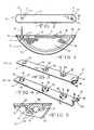
- Fig. 1 is a cut-away side elevational view of an electrochemical cell provided with the header insulator of the present invention;
- Fig. 2 is a top plan view of the lid of the electrochemical cell;
- Fig. 3 is a perspective view of the top of the header insulator of the present invention;
- Fig. 4 is a perspective view of the bottom of the header insulator;
- Fig. 5 is a sectional view taken along lines 5-5 of Fig. 2;
- Fig. 6 is a cut-away side view of an electrochemical cell having an alternate embodiment of the header insulator of the present invention;
- Fig. 7 is a top perspective view of the alternate embodiment of the header insulator; and,
- Fig. 8 is a bottom perspective view of the alternate embodiment of the header insulator.
-
- In Fig. 1, a prismatic
electrochemical cell 10 has a feed-throughpin 13 and afill ferrule 16. Although the present invention is described in connection with a prismatic cell, it is not intended to be limited to that configuration. Accordingly, the present invention is suitable for use with other shapes of battery cases and other electrode assemblies. The general design of the prismaticelectrochemical cell 10 is well known in the art, and an example is provided in U.S. Patent No. 5,750,286 to Paulot et al., which is assigned to the assignee of the present invention and is incorporated herein by reference. The feed-throughpin 13 is connected by aconnection tab 19 to a cathode electrode (hidden underneath the anode). Thepin 13 passes through an opening 21 (shown in Fig. 2) in thelid 22 and is electrically insulated from the anode electrode and thecase 25 including thelid 22 by aglass insulator 24 sealing between thepin 13 and theterminal ferrule 20. Theanode electrode 28 is shown with acurrent collector screen 29 attached thereto by methods known to those of ordinary skill in the art. Theanode electrode 28 has atab connector 31 that preferably connects to the underside of thelid 22 as disclosed in U.S. Patent No. 5,250,373 to Muffoletto, which is assigned to the assignee of the present invention and which is incorporated herein by reference. By connecting the anode electrode to thelid 22, theelectrochemical cell 10 is thereby disposed in the "case negative" configuration. - A
header insulator 34 according to the present invention has afirst boss 37 in registry with theterminal ferrule 20 and asecond boss 40 that partially encapsulates fillferrule 16. Athird boss 43 and afourth boss 46 also extend from the underside of theheader insulator 34 as described herein below. - In Fig. 2, the
lid 22 is preferably planar, elongate and curved atopposite ends lid 22 has an opening 21 for theferrule 20 sealed about the feed-throughpin 13 at thefirst end 49 and an opening 53 for thefill ferrule 16 at theopposite end 52. After thefill ferrule 16 is used to fill thecell 10 with electrolyte, thefill ferrule 16 is sealed as known to those of ordinary skill in the art. An example of a hermetic seal for sealing the electrolyte fill opening is disclosed in U.S. Patent No. 5,776,632 to Honegger, which is assigned to the assignee of the present invention and which is incorporated herein by reference. - Referring to Figs. 3-4, the
header insulator 34 of the present invention for use withprismatic cell 10 is elongate, rectangular, and planar. The choice of materials for the insulator depends on three principal factors: electrical insulation, thermal insulation, and volume. The electrical and thermal insulation properties are necessary to prevent short circuits and to protect the electrode assembly during the welding of thelid 22 to thebattery case 25 and the welding of the seal for thefill ferrule 16. The volume of space required for theheader insulator 34 is to be minimized in order to maximize the available space for electrochemically active materials. - At a
first end 55 of theheader insulator 34, thefirst boss 37 preferably comprises a cylindrically-shaped side wall 56 having anopen end 57 connected to the body of theheader insulator 34. Thecylindrical side wall 56 extends to abottom wall 59 that is parallel to the surface of header-insulator 34 and includes anopening 58 that receives the feed-throughpin 13. The opening 58 is aligned along the longitudinal axis of theboss 37. Thecylindrical side wall 56 andbottom wall 59 of thefirst boss 37 form a recess that snugly receives theterminal ferrule 20. Thefirst boss 37 preferably provides an interference fit with theterminal ferrule 20. Other shapes and sizes for thefirst boss 37 beside cylindrical are also suitable depending on the geometry of theterminal ferrule 20. - At the
opposite end 61 of theinsulator 34, thesecond boss 40 partially encloses and registers with thefill ferrule 16. Thesecond boss 40 is shaped substantially in the form of a bisected cylinder having aside wall 63 and abottom wall 66. As such, thesecond boss 40 partially encloses thefill ferrule 16 and also prevents rotation of theinsulator 34 about theterminal ferrule 20 at thefirst boss 37. - The third and
fourth bosses first boss 37 and thesecond boss 40 along the length of theheader insulator 34. Thebosses side walls 67 andbottom walls 68. Thebottom walls 68 on eachboss 43, 36 are preferably coplanar for maintaining alignment of the electrode assembly inside thecase 25. Theside walls 67 terminate at one end in anopening 70 connected to the main body of theheader insulator 34. At the opposite end, thebottom wall 68 attaches to the end of thecylindrical side walls 67 and is disposed substantially parallel to theheader insulator 34. However, the specific geometry of the bosses is not critical. Other shapes and sizes are also suitable depending on the application. For example, it is contemplated by the scope of the present invention that the boss is a solid member depending downwardly from the plane of the main body of theheader insulator 34. Also, the number ofbosses - The third and fourth or
intermediate bosses case 25 andlid 22. - The
bottom wall 68 preferably hasopenings bosses openings lid 22 and theheader insulator 34. Thebosses header insulator 34 and extend down into the inside of thecase 25 such that the electrode assembly is prevented from moving inside thecase 25. For example, thebosses lid 22 of thecase 25, and a pair of wing portions of the anode extend on each side of the cathode electrode. - Without the
bosses case 25, the battery performance suffers. Accordingly, thebosses - Turning to Fig. 5, the
end 80 of theheader insulator 34 partially surrounds thefill ferrule 16. An example of theseals 90,--93 for thefill ferrule 16 is disclosed in U.S. Patent No. 5,776,632 to Honegger, as described above. - In Fig. 6, an alternate embodiment of the
header insulator 34 of theelectrochemical cell 10 is shown. In the alternate embodiment, the boss 40 (Figs. 1, 3-5) that partially enclosed thefill ferrule 16 has been removed and replaced by an angledplanar member 100. As shown in Figs. 7 and 8, the angledplanar member 100 provides a shield for thefill ferrule 16. Themember 100 substantially shields thefill ferrule 16 from the electrodes such that the fill ferrule does not cause a short circuit and such that the final closing weld does not damage the electrodes. - While the invention has been described in connection with certain preferred embodiments, it is not intended to limit the scope of the invention to the particular forms set forth, but, on the contrary, it is intended to cover such alternatives, modifications, and equivalents as may be included within the spirit and scope of the invention as defined by the appended claims.
Claims (14)
- A header insulator for use with an electrochemical cell having an electrode assembly with an anode electrode and cathode electrode housed in a case open at one end, a lid capable of being sealed to the open end of the case, a terminal ferrule, and a fill ferrule, the header insulator, comprising:a) a body of electrically and thermally insulating material disposed between the electrode assembly and the lid;b) a first boss disposed on the body and sized to register with the terminal ferrule;c) a second boss disposed on the body and sized to register with the fill ferrule; andd) a third boss disposed on the body and sized to prevent movement of the electrode assembly inside the case.
- A header insulator for use with an electrochemical cell having an electrode assembly with an anode electrode and cathode electrode housed in a case open at one end, a lid capable of being sealed to the open end of the case, a terminal ferrule, and a fill ferrule, the header insulator, comprising:a) a body of electrically and thermally insulating material disposed between the electrode assembly and an interior surface of the lid;b) a first boss disposed on the body and sized to register with the terminal ferrule;c) a second boss disposed on the body and sized to prevent movement of the electrode assembly inside the case; and,d) a shield portion disposed on the body at an angle from a remaining portion of the body and extending to cover at least a portion of the fill ferrule.
- A header insulator according to claim 1 or 2, wherein the first boss frictionally fits around the terminal ferrule.
- A header insulator according to any preceding claim, wherein the third boss prevents rotation of the header insulator about the terminal ferrule.
- A header insulator according to any preceding claim, wherein the third boss has an opening disposed therein.
- A header insulator according to any preceding claim, wherein the first boss is substantially cylindrical.
- A header insulator according to any preceding claim, wherein the second boss is in the shape of a bisected cylinder.
- A header insulator according to any preceding claim, wherein the third boss is cylindrical.
- A header insulator according to any preceding claim, where the third boss is solid.
- A header insulator according to any preceding claim, wherein the second boss at least partially encloses the fill ferrule.
- A header according to any of claims 2 to 10, wherein the shield portion is in the shape of a substantially planar member.
- A header insulator according to any of claims 2 to 11, wherein the second boss is cylindrical.
- An electrochemical cell, comprising;a) a case having a surrounding side wall extending to an open end of the case;b) a lid sealed to the open end of the case;c) an electrode assembly having a first electrode and a second electrode, the first electrode and second electrode having a separator disposed therebetween inside the case and being in electrical association with each other;d) a terminal ferrule having a terminal lead with a first end disposed inside the case and connected to the first electrode and a second end adapted to be connected to a load;e) an electrolyte solution activating the first and second electrodes;f) a fill ferrule disposed inside an opening in the lid and capable of receiving the electrolyte solution; andg) a header insulator according to any of the preceding claims.
- A method of providing an electrochemical cell with a header insulator, the electrochemical cell having a terminal ferrule and a fill ferrule, the method comprising the steps of:a) providing a case having a surrounding side wall extending to an open end of the case;b) providing an electrode assembly having a first electrode and a second electrode, the first electrode and second electrode having a separator disposed therebetween inside the case and being in electrical association with each other;c) providing a terminal lead with a first end disposed inside the case and connected to the first electrode and a second end adapted to be connected to a load, the terminal lead capable of passing through the terminal ferrule;d) providing an electrolyte solution activating the first and second electrodes;e) providing a header insulator according to any of the preceding claims.f) sealing a lid to the open end of the case;g) filling the fill ferrule with the electrolyte solution; and,h) sealing the fill opening to the fill ferrule.
Priority Applications (1)
| Application Number | Priority Date | Filing Date | Title |
|---|---|---|---|
| EP03011163A EP1347520A3 (en) | 1999-07-23 | 2000-07-24 | Header for a battery |
Applications Claiming Priority (2)
| Application Number | Priority Date | Filing Date | Title |
|---|---|---|---|
| US09/359,507 US6224999B1 (en) | 1999-07-23 | 1999-07-23 | Header insulator with bosses |
| US359507 | 1999-07-23 |
Related Child Applications (1)
| Application Number | Title | Priority Date | Filing Date |
|---|---|---|---|
| EP03011163A Division EP1347520A3 (en) | 1999-07-23 | 2000-07-24 | Header for a battery |
Publications (3)
| Publication Number | Publication Date |
|---|---|
| EP1071146A2 true EP1071146A2 (en) | 2001-01-24 |
| EP1071146A3 EP1071146A3 (en) | 2002-01-23 |
| EP1071146B1 EP1071146B1 (en) | 2003-10-08 |
Family
ID=23414110
Family Applications (2)
| Application Number | Title | Priority Date | Filing Date |
|---|---|---|---|
| EP03011163A Withdrawn EP1347520A3 (en) | 1999-07-23 | 2000-07-24 | Header for a battery |
| EP00306308A Expired - Lifetime EP1071146B1 (en) | 1999-07-23 | 2000-07-24 | Header insulator |
Family Applications Before (1)
| Application Number | Title | Priority Date | Filing Date |
|---|---|---|---|
| EP03011163A Withdrawn EP1347520A3 (en) | 1999-07-23 | 2000-07-24 | Header for a battery |
Country Status (5)
| Country | Link |
|---|---|
| US (2) | US6224999B1 (en) |
| EP (2) | EP1347520A3 (en) |
| JP (1) | JP2001068075A (en) |
| AT (1) | ATE251802T1 (en) |
| DE (1) | DE60005759T2 (en) |
Cited By (2)
| Publication number | Priority date | Publication date | Assignee | Title |
|---|---|---|---|---|
| EP1347520A2 (en) * | 1999-07-23 | 2003-09-24 | Wilson Greatbatch Ltd. | Header for a battery |
| CN103022584A (en) * | 2012-12-21 | 2013-04-03 | 中银(宁波)电池有限公司 | 4.5V assembled battery |
Families Citing this family (11)
| Publication number | Priority date | Publication date | Assignee | Title |
|---|---|---|---|---|
| US6670074B2 (en) * | 2001-04-23 | 2003-12-30 | Wilson Greatbatch Ltd. | Glass to metal seal |
| US7294432B2 (en) * | 2003-11-26 | 2007-11-13 | Medtronic, Inc. | Battery having improved headspace insulator |
| US20060096082A1 (en) * | 2004-10-29 | 2006-05-11 | Aamodt Paul B | Flat plate electrochemical cell head space insulator |
| US20060096958A1 (en) * | 2004-10-29 | 2006-05-11 | Hailiang Zhao | Laser penetration weld |
| US20060166088A1 (en) * | 2005-01-26 | 2006-07-27 | Hokanson Karl E | Electrode connector tabs |
| DE102011103975A1 (en) * | 2011-06-10 | 2012-12-13 | Schott Ag | Feed-through component for feeding conductors for lithium ion battery used for portable electronic device, has electrode connecting portion which are mechanically connected with head portions through welding process |
| US11462789B2 (en) | 2011-02-18 | 2022-10-04 | Schott Ag | Base body for feeding through of a conductor, and a housing component of a housing, in particular a battery housing comprising said base body |
| US10224521B2 (en) | 2011-02-18 | 2019-03-05 | Schott Ag | Feed-through |
| KR102155247B1 (en) | 2011-02-18 | 2020-09-11 | 쇼오트 아게 | Feedthrough |
| DE102014018975A1 (en) * | 2014-12-18 | 2016-06-23 | Daimler Ag | Battery cell for a motor vehicle battery |
| JP7276479B2 (en) | 2019-09-30 | 2023-05-18 | 株式会社村田製作所 | flat secondary battery |
Citations (5)
| Publication number | Priority date | Publication date | Assignee | Title |
|---|---|---|---|---|
| US4242425A (en) * | 1980-02-21 | 1980-12-30 | Catalyst Research Corporation | Novel lithium halide battery structure |
| US4601962A (en) * | 1981-01-05 | 1986-07-22 | Wilson Greatbatch Ltd. | Anode assembly for lithium-halogen cell |
| US5312458A (en) * | 1991-09-10 | 1994-05-17 | Wilson Greatbatch Ltd. | Internal electrode and assembly method for electrochemical cells |
| US5624767A (en) * | 1995-06-07 | 1997-04-29 | Wilson Greatbatch Ltd. | Alkali metal cell having main and alternate electrodes |
| US5811206A (en) * | 1997-10-31 | 1998-09-22 | Medtronic, Inc. | Feedthrough pin insulator, assembly and method for electrochemical cell |
Family Cites Families (10)
| Publication number | Priority date | Publication date | Assignee | Title |
|---|---|---|---|---|
| US2527576A (en) | 1944-06-29 | 1950-10-31 | Ruben Samuel | Flat primary cell |
| US4191806A (en) | 1978-08-28 | 1980-03-04 | Esb Incorporated | Pressure vent for a sealed primary cell |
| US4320182A (en) | 1979-11-21 | 1982-03-16 | General Electric Company | Electrochemical cell having cast-in-place insulator |
| US4637966A (en) | 1983-10-21 | 1987-01-20 | Gates Energy Products, Inc. | Sealed lead-acid cell |
| US5434017A (en) | 1993-11-19 | 1995-07-18 | Medtronic, Inc. | Isolated connection for an electrochemical cell |
| US5626988A (en) | 1994-05-06 | 1997-05-06 | Battery Technologies Inc. | Sealed rechargeable cells containing mercury-free zinc anodes, and a method of manufacture |
| US5674639A (en) | 1995-06-07 | 1997-10-07 | Eveready Battery Company | Separator for alkaline electrochemical cells |
| US5750286A (en) * | 1996-07-31 | 1998-05-12 | Wilson Greatbatch Ltd. | Dual connection tab current collector |
| US6224999B1 (en) * | 1999-07-23 | 2001-05-01 | Wilson Greatbatch Ltd. | Header insulator with bosses |
| US6686088B2 (en) * | 1999-07-23 | 2004-02-03 | Wilson Greatbatch Ltd. | Header insulator for an electrochemical cell |
-
1999
- 1999-07-23 US US09/359,507 patent/US6224999B1/en not_active Expired - Lifetime
-
2000
- 2000-07-24 DE DE60005759T patent/DE60005759T2/en not_active Expired - Fee Related
- 2000-07-24 AT AT00306308T patent/ATE251802T1/en not_active IP Right Cessation
- 2000-07-24 EP EP03011163A patent/EP1347520A3/en not_active Withdrawn
- 2000-07-24 EP EP00306308A patent/EP1071146B1/en not_active Expired - Lifetime
- 2000-07-24 JP JP2000221796A patent/JP2001068075A/en active Pending
-
2001
- 2001-04-27 US US09/844,639 patent/US6475669B2/en not_active Expired - Lifetime
Patent Citations (5)
| Publication number | Priority date | Publication date | Assignee | Title |
|---|---|---|---|---|
| US4242425A (en) * | 1980-02-21 | 1980-12-30 | Catalyst Research Corporation | Novel lithium halide battery structure |
| US4601962A (en) * | 1981-01-05 | 1986-07-22 | Wilson Greatbatch Ltd. | Anode assembly for lithium-halogen cell |
| US5312458A (en) * | 1991-09-10 | 1994-05-17 | Wilson Greatbatch Ltd. | Internal electrode and assembly method for electrochemical cells |
| US5624767A (en) * | 1995-06-07 | 1997-04-29 | Wilson Greatbatch Ltd. | Alkali metal cell having main and alternate electrodes |
| US5811206A (en) * | 1997-10-31 | 1998-09-22 | Medtronic, Inc. | Feedthrough pin insulator, assembly and method for electrochemical cell |
Cited By (4)
| Publication number | Priority date | Publication date | Assignee | Title |
|---|---|---|---|---|
| EP1347520A2 (en) * | 1999-07-23 | 2003-09-24 | Wilson Greatbatch Ltd. | Header for a battery |
| EP1347520A3 (en) * | 1999-07-23 | 2003-10-01 | Wilson Greatbatch Ltd. | Header for a battery |
| CN103022584A (en) * | 2012-12-21 | 2013-04-03 | 中银(宁波)电池有限公司 | 4.5V assembled battery |
| CN103022584B (en) * | 2012-12-21 | 2014-12-24 | 中银(宁波)电池有限公司 | 4.5V assembled battery |
Also Published As
| Publication number | Publication date |
|---|---|
| EP1071146A3 (en) | 2002-01-23 |
| EP1347520A2 (en) | 2003-09-24 |
| DE60005759T2 (en) | 2004-08-19 |
| EP1347520A3 (en) | 2003-10-01 |
| US20010016280A1 (en) | 2001-08-23 |
| JP2001068075A (en) | 2001-03-16 |
| US6475669B2 (en) | 2002-11-05 |
| DE60005759D1 (en) | 2003-11-13 |
| EP1071146B1 (en) | 2003-10-08 |
| ATE251802T1 (en) | 2003-10-15 |
| US6224999B1 (en) | 2001-05-01 |
Similar Documents
| Publication | Publication Date | Title |
|---|---|---|
| AU660699B2 (en) | Internal electrode and assembly method for electrochemical cells | |
| US5744261A (en) | Insulating inclosure for lithium batteries | |
| EP1071146B1 (en) | Header insulator | |
| US7128765B2 (en) | Method for providing a one-piece header assembly for hermetic battery terminal feedthrough, fill and closure designs | |
| US5750286A (en) | Dual connection tab current collector | |
| US7550227B2 (en) | Secondary battery | |
| US6759163B2 (en) | Mismatched compression glass-to-metal seal | |
| US8685561B2 (en) | Rechargeable battery | |
| US5624767A (en) | Alkali metal cell having main and alternate electrodes | |
| KR100274889B1 (en) | Cab assembly of prismatic secondary battery | |
| KR100277655B1 (en) | Cap assembly of secondary battery and method for making the same | |
| EP1249879A2 (en) | Low profile battery termination | |
| US6686088B2 (en) | Header insulator for an electrochemical cell | |
| KR20000009697A (en) | Cylindrical battery of a heat dissipation device | |
| KR100553739B1 (en) | Sealed battery | |
| KR100325861B1 (en) | Sealed battery | |
| KR100669670B1 (en) | Prismatic type sealed battery | |
| KR100544106B1 (en) | Can used in secondary battery | |
| US6589691B2 (en) | Structural feed through arrangement for lithium ion cells | |
| US5512388A (en) | Side cover battery cell assembly | |
| KR20040022717A (en) | Lithium secondary battery with improved terminal structure | |
| KR19990002562U (en) | Secondary battery | |
| KR20000060914A (en) | Prismatic type secondary battery | |
| KR20010039434A (en) | Sealed battery | |
| JPH01255168A (en) | Disc type oxyhalide lithium battery |
Legal Events
| Date | Code | Title | Description |
|---|---|---|---|
| PUAI | Public reference made under article 153(3) epc to a published international application that has entered the european phase |
Free format text: ORIGINAL CODE: 0009012 |
|
| AK | Designated contracting states |
Kind code of ref document: A2 Designated state(s): AT BE CH CY DE DK ES FI FR GB GR IE IT LI LU MC NL PT SE |
|
| AX | Request for extension of the european patent |
Free format text: AL;LT;LV;MK;RO;SI |
|
| PUAL | Search report despatched |
Free format text: ORIGINAL CODE: 0009013 |
|
| AK | Designated contracting states |
Kind code of ref document: A3 Designated state(s): AT BE CH CY DE DK ES FI FR GB GR IE IT LI LU MC NL PT SE |
|
| AX | Request for extension of the european patent |
Free format text: AL;LT;LV;MK;RO;SI |
|
| 17P | Request for examination filed |
Effective date: 20020124 |
|
| AKX | Designation fees paid |
Free format text: AT BE CH CY DE DK ES FI FR GB GR IE IT LI LU MC NL PT SE |
|
| GRAH | Despatch of communication of intention to grant a patent |
Free format text: ORIGINAL CODE: EPIDOS IGRA |
|
| GRAH | Despatch of communication of intention to grant a patent |
Free format text: ORIGINAL CODE: EPIDOS IGRA |
|
| GRAA | (expected) grant |
Free format text: ORIGINAL CODE: 0009210 |
|
| AK | Designated contracting states |
Kind code of ref document: B1 Designated state(s): AT BE CH CY DE DK ES FI FR GB GR IE IT LI LU MC NL PT SE |
|
| PG25 | Lapsed in a contracting state [announced via postgrant information from national office to epo] |
Ref country code: AT Free format text: LAPSE BECAUSE OF FAILURE TO SUBMIT A TRANSLATION OF THE DESCRIPTION OR TO PAY THE FEE WITHIN THE PRESCRIBED TIME-LIMIT Effective date: 20031008 Ref country code: BE Free format text: LAPSE BECAUSE OF FAILURE TO SUBMIT A TRANSLATION OF THE DESCRIPTION OR TO PAY THE FEE WITHIN THE PRESCRIBED TIME-LIMIT Effective date: 20031008 Ref country code: FI Free format text: LAPSE BECAUSE OF FAILURE TO SUBMIT A TRANSLATION OF THE DESCRIPTION OR TO PAY THE FEE WITHIN THE PRESCRIBED TIME-LIMIT Effective date: 20031008 Ref country code: CY Free format text: LAPSE BECAUSE OF FAILURE TO SUBMIT A TRANSLATION OF THE DESCRIPTION OR TO PAY THE FEE WITHIN THE PRESCRIBED TIME-LIMIT Effective date: 20031008 |
|
| REG | Reference to a national code |
Ref country code: GB Ref legal event code: FG4D |
|
| REG | Reference to a national code |
Ref country code: CH Ref legal event code: EP |
|
| REG | Reference to a national code |
Ref country code: IE Ref legal event code: FG4D |
|
| REF | Corresponds to: |
Ref document number: 60005759 Country of ref document: DE Date of ref document: 20031113 Kind code of ref document: P |
|
| REG | Reference to a national code |
Ref country code: CH Ref legal event code: NV Representative=s name: ISLER & PEDRAZZINI AG |
|
| REG | Reference to a national code |
Ref country code: SE Ref legal event code: TRGR |
|
| PG25 | Lapsed in a contracting state [announced via postgrant information from national office to epo] |
Ref country code: DK Free format text: LAPSE BECAUSE OF FAILURE TO SUBMIT A TRANSLATION OF THE DESCRIPTION OR TO PAY THE FEE WITHIN THE PRESCRIBED TIME-LIMIT Effective date: 20040108 Ref country code: GR Free format text: LAPSE BECAUSE OF FAILURE TO SUBMIT A TRANSLATION OF THE DESCRIPTION OR TO PAY THE FEE WITHIN THE PRESCRIBED TIME-LIMIT Effective date: 20040108 |
|
| PG25 | Lapsed in a contracting state [announced via postgrant information from national office to epo] |
Ref country code: ES Free format text: LAPSE BECAUSE OF FAILURE TO SUBMIT A TRANSLATION OF THE DESCRIPTION OR TO PAY THE FEE WITHIN THE PRESCRIBED TIME-LIMIT Effective date: 20040119 |
|
| ET | Fr: translation filed | ||
| PGFP | Annual fee paid to national office [announced via postgrant information from national office to epo] |
Ref country code: NL Payment date: 20040716 Year of fee payment: 5 |
|
| PGFP | Annual fee paid to national office [announced via postgrant information from national office to epo] |
Ref country code: CH Payment date: 20040721 Year of fee payment: 5 |
|
| PG25 | Lapsed in a contracting state [announced via postgrant information from national office to epo] |
Ref country code: LU Free format text: LAPSE BECAUSE OF NON-PAYMENT OF DUE FEES Effective date: 20040724 |
|
| PG25 | Lapsed in a contracting state [announced via postgrant information from national office to epo] |
Ref country code: IE Free format text: LAPSE BECAUSE OF NON-PAYMENT OF DUE FEES Effective date: 20040726 |
|
| PG25 | Lapsed in a contracting state [announced via postgrant information from national office to epo] |
Ref country code: MC Free format text: LAPSE BECAUSE OF NON-PAYMENT OF DUE FEES Effective date: 20040731 |
|
| PLBE | No opposition filed within time limit |
Free format text: ORIGINAL CODE: 0009261 |
|
| STAA | Information on the status of an ep patent application or granted ep patent |
Free format text: STATUS: NO OPPOSITION FILED WITHIN TIME LIMIT |
|
| 26N | No opposition filed |
Effective date: 20040709 |
|
| REG | Reference to a national code |
Ref country code: IE Ref legal event code: MM4A |
|
| PG25 | Lapsed in a contracting state [announced via postgrant information from national office to epo] |
Ref country code: IT Free format text: LAPSE BECAUSE OF NON-PAYMENT OF DUE FEES Effective date: 20050724 |
|
| PG25 | Lapsed in a contracting state [announced via postgrant information from national office to epo] |
Ref country code: CH Free format text: LAPSE BECAUSE OF NON-PAYMENT OF DUE FEES Effective date: 20050731 Ref country code: LI Free format text: LAPSE BECAUSE OF NON-PAYMENT OF DUE FEES Effective date: 20050731 |
|
| PGFP | Annual fee paid to national office [announced via postgrant information from national office to epo] |
Ref country code: GB Payment date: 20050812 Year of fee payment: 6 |
|
| PGFP | Annual fee paid to national office [announced via postgrant information from national office to epo] |
Ref country code: FR Payment date: 20050819 Year of fee payment: 6 |
|
| PGFP | Annual fee paid to national office [announced via postgrant information from national office to epo] |
Ref country code: SE Payment date: 20050823 Year of fee payment: 6 |
|
| PGFP | Annual fee paid to national office [announced via postgrant information from national office to epo] |
Ref country code: DE Payment date: 20050831 Year of fee payment: 6 |
|
| PG25 | Lapsed in a contracting state [announced via postgrant information from national office to epo] |
Ref country code: NL Free format text: LAPSE BECAUSE OF NON-PAYMENT OF DUE FEES Effective date: 20060201 |
|
| REG | Reference to a national code |
Ref country code: CH Ref legal event code: PL |
|
| NLV4 | Nl: lapsed or anulled due to non-payment of the annual fee |
Effective date: 20060201 |
|
| PG25 | Lapsed in a contracting state [announced via postgrant information from national office to epo] |
Ref country code: GB Free format text: LAPSE BECAUSE OF NON-PAYMENT OF DUE FEES Effective date: 20060724 |
|
| PG25 | Lapsed in a contracting state [announced via postgrant information from national office to epo] |
Ref country code: SE Free format text: LAPSE BECAUSE OF NON-PAYMENT OF DUE FEES Effective date: 20060725 |
|
| PG25 | Lapsed in a contracting state [announced via postgrant information from national office to epo] |
Ref country code: DE Free format text: LAPSE BECAUSE OF NON-PAYMENT OF DUE FEES Effective date: 20070201 |
|
| EUG | Se: european patent has lapsed | ||
| GBPC | Gb: european patent ceased through non-payment of renewal fee |
Effective date: 20060724 |
|
| REG | Reference to a national code |
Ref country code: FR Ref legal event code: ST Effective date: 20070330 |
|
| PG25 | Lapsed in a contracting state [announced via postgrant information from national office to epo] |
Ref country code: PT Free format text: LAPSE BECAUSE OF NON-PAYMENT OF DUE FEES Effective date: 20040308 |
|
| PG25 | Lapsed in a contracting state [announced via postgrant information from national office to epo] |
Ref country code: FR Free format text: LAPSE BECAUSE OF NON-PAYMENT OF DUE FEES Effective date: 20060731 |