EP1071381B1 - Stent deployment device - Google Patents
Stent deployment device Download PDFInfo
- Publication number
- EP1071381B1 EP1071381B1 EP99918755A EP99918755A EP1071381B1 EP 1071381 B1 EP1071381 B1 EP 1071381B1 EP 99918755 A EP99918755 A EP 99918755A EP 99918755 A EP99918755 A EP 99918755A EP 1071381 B1 EP1071381 B1 EP 1071381B1
- Authority
- EP
- European Patent Office
- Prior art keywords
- stent
- endoscope
- sheath
- protective cap
- distal end
- Prior art date
- Legal status (The legal status is an assumption and is not a legal conclusion. Google has not performed a legal analysis and makes no representation as to the accuracy of the status listed.)
- Expired - Lifetime
Links
Images


Classifications
-
- A—HUMAN NECESSITIES
- A61—MEDICAL OR VETERINARY SCIENCE; HYGIENE
- A61F—FILTERS IMPLANTABLE INTO BLOOD VESSELS; PROSTHESES; DEVICES PROVIDING PATENCY TO, OR PREVENTING COLLAPSING OF, TUBULAR STRUCTURES OF THE BODY, e.g. STENTS; ORTHOPAEDIC, NURSING OR CONTRACEPTIVE DEVICES; FOMENTATION; TREATMENT OR PROTECTION OF EYES OR EARS; BANDAGES, DRESSINGS OR ABSORBENT PADS; FIRST-AID KITS
- A61F2/00—Filters implantable into blood vessels; Prostheses, i.e. artificial substitutes or replacements for parts of the body; Appliances for connecting them with the body; Devices providing patency to, or preventing collapsing of, tubular structures of the body, e.g. stents
- A61F2/95—Instruments specially adapted for placement or removal of stents or stent-grafts
- A61F2002/9505—Instruments specially adapted for placement or removal of stents or stent-grafts having retaining means other than an outer sleeve, e.g. male-female connector between stent and instrument
- A61F2002/9511—Instruments specially adapted for placement or removal of stents or stent-grafts having retaining means other than an outer sleeve, e.g. male-female connector between stent and instrument the retaining means being filaments or wires
Definitions
- the present invention relates to stent deployment devices and methods for deploying stents. More particularly, the present invention concerns a stent deployment device for deploying a stent within the alimentary tract using an endoscope.
- Endoscopes are effective devices for diagnosing and treating patients with minimal intervention and discomfort and are often used to explore and perform biopsies in such areas as the alimentary tract.
- an endoscope has a flexible elongated tubular body equipped with a miniature television camera or other viewing device, a light, and a working lumen or channel.
- the working channel is used to store and deploy a variety of surgical tools for different endoscopic operations.
- a stent is a resilient device often used in anchoring vascular grafts and for supporting body openings during the grafting of vessels and tubes of the body during surgery. Also, stents are frequently used, without grafts, for supporting lumenal patency. More recently, artificial (woven or nonwoven polymeric) grafts are used in cardiac, vascular and nonvascular applications to provide extra support. Moreover, stents can be separated into self expanding and plastically deformed stents. A self expanding stent is deployed by its self expanding resilience. A plastically deformed stent is deployed by plastic deformation of the constituent material with a balloon or other such dilating instrument.
- Endoscopes are effectively utilized to deploy stents within a body cavity in a minimally invasive manner.
- a stent is compressed to fit into the working channel of the endoscope and is delivered to the body cavity to be treated.
- storing a stent within the working channel of an endoscope causes several problems.
- stents are made of resilient material, compression within the working channel can cause the stent to become deformed and fail to return to its original shape if strained beyond a certain point. The more the stent gets strained, the more extreme the deformation is likely to be.
- Known devices for deploying stents are mentioned in WO97/48343 which simply discloses a tubular cover for a stent while WO98/11846 discusses an intra cranial stent with a sliding release mechanism at a proximal end of a catheter.
- WO97/48343 simply discloses a tubular cover for a stent
- WO98/11846 discusses an intra cranial stent with a sliding release mechanism at a proximal end of a catheter.
- a stent deployment device as set out in claim 1.
- the present invention utilizes an endoscope having a distal end and a working channel.
- a protective cap is mounted on the distal end of the endoscope.
- a flexible stent is circumferentially compressed over the perimeter of the protective cap.
- a sheath is releasably wrapped around the stent to hold it in its compressed configuration over the cap.
- One end of a flexible, elongated member such as a wire or other flexible member, is attached to the sheath to permit removal from the cap and stent and deployment of the stent in substantially linear transverse alignment within a body cavity.
- the elongated member extends through the working channel of the endoscope and exits from the distal end thereof.
- the stent deployment device comprises one end of a flexible, elongated member attached to a release device for removing a sheath from a cap and deploying the stent in substantially linear transverse alignment within a body cavity.
- the stent deployment device comprises a protective cap adapted for mounting on the distal end of the endoscope with a sheath that is releasably wrapped around the stent to hold the stent in a compressed configuration over the cap.
- a flexible, elongated member is attached to the sheath to permit its release and deployment in substantially linear transverse alignment within a body cavity by withdrawing the elongated member extending through the working channel of the endoscope, the elongated member exiting from the distal end of the endoscope.
- one end of a flexible, elongated member extending through the working channel is attached to a release device for removing a sheath from a cap and deploying a stent in substantially linear transverse alignment within a body cavity by withdrawing the elongated member.
- a method including the steps of mounting a protective cap on a distal end of an endoscope, compressing a stent circumferentially over the perimeter of the protective cap, releasably wrapping a sheath around the stent to hold the stent in a compressed configuration over the protective cap and withdrawing the flexible, elongated member engaged with the sheath through the endoscope to release the sheath from the protective cap, thereby causing the stent to deploy.
- the stent deployment device is used with an endoscope, and includes a protective cap, a flexible stent, a sheath, and a flexible, elongated member connected to the sheath, such as a wire or other flexible member.
- the devices and methods of the present invention enable deployment of a stent in substantially linear transverse alignment within a body cavity.
- an endoscope 10 has a flexible elongated tubular body with a distal end 12 for insertion into a body cavity.
- endoscope 10 is equipped with an illumination device 14, a viewing device 16, and a working lumen or channel 18.
- the illumination device 14 provides light for the operation of the endoscope in a dark body cavity.
- the working channel 18 extends through the tubular body to the distal end 12 of endoscope 10.
- the working channel 18 is designed to accommodate various medical instruments, which can include a stent.
- the endoscope 10 has a protective cap 20 mounted onto its distal end 12.
- the protective cap 20 provides a base surface for retaining stent 22 and protects the body of the endoscope 10 from any abrasion by the stent deployment.
- the protective cap 20 is made of silicone or other elastomers, such as polyurethane, latex and certain nylons, and has a tubular shape.
- the protective cap 20 may be mounted at the distal end 12 by gripping onto the circumference of the distal end 12. Also, the protective cap 20 may be clipped onto the distal end 12.
- the stent 22 is a flexible device preferably made of a resilient material, and substantially returns to its original shape in the absence of any restraint.
- Materials suitable for the stent include nickel-titanium alloy (Nitinol), medical grade stainless steels, tantalum and other biocompatible metals. Also, certain polymers may be suitable for the stent although some polymers do not have changeable diameters.
- the stent 22 is circumferentially wrapped and compressed around and over the perimeter of the cap 20. This configuration allows the stent to be retained outside of the endoscope 10 rather than inside.
- the stent 22 has a compressed diameter of approximately 1.0 cm.
- a sheath 24 is wrapped around the stent 22 to hold it in a compressed configuration over the cap 20. Once the sheath 24 is removed from cap 20 and the stent 22 in the body cavity, stent 22 deploys within the body cavity in substantially its original shape in order to effectively support the body cavity.
- the sheath 24 is preferably a thin strip made of Teflon, polyethylene, or any other appropriate material safe to the body, such as polymer films, polyimide, and nylons.
- the sheath 24 can be a sheet that is wrapped around the endoscope 10 body into a tubular shape.
- the sheath 24 also can have a seamless tubular shape.
- the sheath 24 holds stent 22 in a compressed form and stays wrapped around the stent 22 due to friction between the sheath 24 and stent 22 surfaces.
- the length of the sheath 24 largely depends on the length of the stent 22, but the sheath is preferably longer than the stent 22.
- sheath 24 is preferably about 10 cm. long for retaining a 6 cm. stent 22. As the stent becomes longer in circumference, the relevant length is a bound down stent length when the diameter of the stent is constrained.
- a flexible, elongated member 26 extends though the working channel 18 of endoscope 10 and is attached to sheath 24 at connection point 27 for removal of the sheath 24.
- the elongated member 26 is preferably a pull-wire extending through the working channel 18 of the endoscope 10.
- the elongated member 26 can be permanently attached to a part of the sheath if at point 27 and remains attached to sheath 24 after it is removed from the cap 20 and the stent 22.
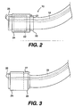
- the sheath 24, wrapped around the protective cap 20 and the stent 22, is released by pulling the elongated member 26 in the direction shown in Fig. 2. As shown in Figs. 1 and 2, the elongated member 26 extends between the sheath 24 and the stent 22 when it is pulled to release the sheath 24. When the elongated member 26 is pulled in the direction shown in Fig. 2, the sheath 24 extends away from distal end 12. Sheath 24 is then drawn through the working channel 18. This configuration is preferable because then the sheath 24 is not left in the body cavity, thus eliminating any need to later retrieve it. After sheath 24 is removed, the stent 22 is free to deploy and will extend in a substantially traverse direction in the body cavity.
- a second preferred embodiment of the present invention illustrated in Fig. 3, has a perforated portion 28 along the sheath 24.
- Elongated member 26 is attached to perforated portion 28 at point 27.
- Perforated portion 28 is torn away from the remainder of sheath 24 when the elongated member 26 is pulled through the working channel 18, thus releasing the sheath 24 and deploying the stent 22.
- the sheath 24, with the exception of the perforated portion 28, is left in the body cavity. It may be preferable to leave the sheath 24 within the body cavity if extracting the endoscope 10 with the sheath 24 would likely result in damage to the body cavity, such as small intestines.
- the portion of sheath 24 left in the body cavity is subsequently retrieved by another endoscopic device extended through working channel 18.
- Fig. 4 illustrates a third preferred embodiment of a stent employment device of present invention.
- the elongated member 26 is attached to a release device 29 at point 27, which preferably comprises a ring 30 having a flanged portion 32 for removing the sheath 24.
- the ring 30 is preferably made of biocompatible metal, such as stainless steel or an engineering plastic like acetal. As the elongated member 26 is pulled through the working channel 18, the ring 30 begins to slide to the distal end 12 of the endoscope 10 over the cap 20 and the stent (not shown in the Fig. 4).
- the flanged portion 32 engages with the sheath 24 and pushes the sheath 24 from the cap 20 and the stent as the ring 30 slides toward the distal end 12 of the endoscope 10, thus releasing the sheath 24, and deploying the stent into the body cavity.
- the ring-30 can either stay on the cap or completely off the cap after the operation. However, the ring 30 preferably stays on the cap in order to facilitate the removal of the endoscope from the body cavity.
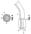
- the elongated member 26 is attached at point 27 to a release device comprising an inner ring 34 and an outer ring 36 concentrically arranged over the cap 20 and the stent (not shown in Figs. 5 and 6).
- a release device comprising an inner ring 34 and an outer ring 36 concentrically arranged over the cap 20 and the stent (not shown in Figs. 5 and 6).
- the sheath 24 and one end of the elongated member 26 are compressed by the inner ring 34 and the outer ring 36.
- the rings 34 and 36 are preferably made of steel or a ductile metal such as tantalum.
- the outer ring 36 is a swage ring for compressing the sheath 24 and the elongated member 26.
- the inner ring 34 When the elongated member 26 is pulled through the working channel 18, the inner ring 34, together with the sheath 24, the elongated member 26 and the outer ring 36, slide over the cap 20 and the stent toward the distal end 12, thus releasing the sheath 24 from the cap and deploying the stent.
- the rings preferably fall off the cap after the sheath is released.
- Fig. 7 illustrates a removable peel away member 38 that holds the sheath 24 in a closed position wrapped around the stent (not shown in Fig. 7).
- the peel away member is preferably made of the same material as the sheath, such as polyesters or polyethylenes.
- Elongated member 26 is attached to the peel away member and is pulled through the working channel 18 to remove the peel way member 38 from the sheath 24, thus releasing the sheath 24 from the cap 20 to deploy the stent into the body cavity.
- the sheath 24 completely wraps around the stent. The sheath 24 can then be left in the body cavity after it is removed from the cap 20 and the stent.
- a method of deploying the stent 22 within a body cavity comprises the following steps.
- the protective cap 20 is mounted on the distal end 12 of an endoscope 10 and-the stent 22 is compressed circumferentially over the perimeter of the protective cap 20.
- the sheath 24 is releasably wrapped around the stent 22 to hold it in a compressed configuration over the protective cap 20.
- the sheath 24 has the flexible, elongated member 26 engaged with the sheath 24 extending through a working channel 18 of the endoscope 10.
- the endoscope is then inserted into a body cavity to the site of stent deployment.
- the flexible, elongated member 26 is withdrawn through the working channel 18 to release the sheath 24 from the cap 20, thereby causing the stent 22 to deploy.
- the order of these steps can be altered. For instance, the cap 20, the stent 22, and the sheath 24 may be assembled first, and then the assembly may be placed on to the distal end 12 of an endoscope.
Abstract
Description
- The present invention relates to stent deployment devices and methods for deploying stents. More particularly, the present invention concerns a stent deployment device for deploying a stent within the alimentary tract using an endoscope.
- Endoscopes are effective devices for diagnosing and treating patients with minimal intervention and discomfort and are often used to explore and perform biopsies in such areas as the alimentary tract. In general, an endoscope has a flexible elongated tubular body equipped with a miniature television camera or other viewing device, a light, and a working lumen or channel. The working channel is used to store and deploy a variety of surgical tools for different endoscopic operations.
- A stent is a resilient device often used in anchoring vascular grafts and for supporting body openings during the grafting of vessels and tubes of the body during surgery. Also, stents are frequently used, without grafts, for supporting lumenal patency. More recently, artificial (woven or nonwoven polymeric) grafts are used in cardiac, vascular and nonvascular applications to provide extra support. Moreover, stents can be separated into self expanding and plastically deformed stents. A self expanding stent is deployed by its self expanding resilience. A plastically deformed stent is deployed by plastic deformation of the constituent material with a balloon or other such dilating instrument.
- Endoscopes are effectively utilized to deploy stents within a body cavity in a minimally invasive manner. In a conventional method, a stent is compressed to fit into the working channel of the endoscope and is delivered to the body cavity to be treated. However, storing a stent within the working channel of an endoscope causes several problems. First, there is a limitation on the size of the stent that can be compressed to fit in the working channel. Because the working channel of the endoscope is often relatively small, a large stent may not fit within the working channel. Thus, this method is not suitable for deploying large stents.
- Additionally, fitting a stent in the working channel often results in extreme deformation of the stent when it is deployed to the body cavity. Since stents are made of resilient material, compression within the working channel can cause the stent to become deformed and fail to return to its original shape if strained beyond a certain point. The more the stent gets strained, the more extreme the deformation is likely to be. Known devices for deploying stents are mentioned in WO97/48343 which simply discloses a tubular cover for a stent while WO98/11846 discusses an intra cranial stent with a sliding release mechanism at a proximal end of a catheter. However, there is a need for stent deployment systems and methods that provide a solution to aforementioned problems and permit deployment of stents, regardless of size, into body cavities.
- In accordance with the present invention there is provided a stent deployment device as set out in claim 1. As embodied and broadly described herein, the present invention utilizes an endoscope having a distal end and a working channel. A protective cap is mounted on the distal end of the endoscope. A flexible stent is circumferentially compressed over the perimeter of the protective cap. A sheath is releasably wrapped around the stent to hold it in its compressed configuration over the cap. One end of a flexible, elongated member, such as a wire or other flexible member, is attached to the sheath to permit removal from the cap and stent and deployment of the stent in substantially linear transverse alignment within a body cavity. The elongated member extends through the working channel of the endoscope and exits from the distal end thereof.
- In accordance with another aspect of the present invention, the stent deployment device comprises one end of a flexible, elongated member attached to a release device for removing a sheath from a cap and deploying the stent in substantially linear transverse alignment within a body cavity.
- In yet another aspect of the present invention, the stent deployment device comprises a protective cap adapted for mounting on the distal end of the endoscope with a sheath that is releasably wrapped around the stent to hold the stent in a compressed configuration over the cap. One end of a flexible, elongated member is attached to the sheath to permit its release and deployment in substantially linear transverse alignment within a body cavity by withdrawing the elongated member extending through the working channel of the endoscope, the elongated member exiting from the distal end of the endoscope.
- In still another aspect of the present invention, one end of a flexible, elongated member extending through the working channel is attached to a release device for removing a sheath from a cap and deploying a stent in substantially linear transverse alignment within a body cavity by withdrawing the elongated member.
- There is also provided a method , being not a part of the present invention, including the steps of mounting a protective cap on a distal end of an endoscope, compressing a stent circumferentially over the perimeter of the protective cap, releasably wrapping a sheath around the stent to hold the stent in a compressed configuration over the protective cap and withdrawing the flexible, elongated member engaged with the sheath through the endoscope to release the sheath from the protective cap, thereby causing the stent to deploy.
- It is also to be understood thatboth the foregoing general description and the following detailed description are exemplary and explanatory only and are not restrictive of the invention, as claimed.
- The accompanying drawings, which are incorporated in and constitute a part of this specification, illustrate several embodiments of the invention and together with the description, serve to explain the principles of the invention. In the drawings:
- Fig. 1 is an exploded view of a first embodiment of the stent deployment device according to the present invention.
- Fig. 2 is a non-exploded side view of the stent deployment device illustrated in Fig. 1.
- Fig. 3 is a side view of a second embodiment of a stent deployment device in accordance with the present invention.
- Fig. 4 is a side view of a third embodiment of a stent deployment device in accordance with the present invention.
- Fig. 5 is a side view of a fourth embodiment of a stent deployment device in accordance with the present invention.
- Fig. 6 is a cross-sectional view along line A-A of Fig. 5.
- Fig. 7 is a side view of another stent deployment device.
- Reference will now be made in detail to the present preferred embodiments of the present invention, examples of which are illustrated in the accompanying drawings. Wherever possible, the same reference numbers will be used throughout the drawings to refer to the same or like parts.
- In accordance with the present invention, the stent deployment device is used with an endoscope, and includes a protective cap, a flexible stent, a sheath, and a flexible, elongated member connected to the sheath, such as a wire or other flexible member. The devices and methods of the present invention enable deployment of a stent in substantially linear transverse alignment within a body cavity.
- In a first preferred embodiment of the present invention, illustrated in Figs. 1 and 2, an
endoscope 10 has a flexible elongated tubular body with adistal end 12 for insertion into a body cavity. Generally,endoscope 10 is equipped with an illumination device 14, aviewing device 16, and a working lumen orchannel 18. The illumination device 14 provides light for the operation of the endoscope in a dark body cavity. Theviewing device 16, which may be a TV camera, captures images in the body cavity, and the images are electrically or optically transmitted through the tubular body ofendoscope 10. The workingchannel 18 extends through the tubular body to thedistal end 12 ofendoscope 10. The workingchannel 18 is designed to accommodate various medical instruments, which can include a stent. - As shown in Figs. 1 and 2, the
endoscope 10 has aprotective cap 20 mounted onto itsdistal end 12. Theprotective cap 20 provides a base surface for retainingstent 22 and protects the body of theendoscope 10 from any abrasion by the stent deployment. Preferably, theprotective cap 20 is made of silicone or other elastomers, such as polyurethane, latex and certain nylons, and has a tubular shape. Theprotective cap 20 may be mounted at thedistal end 12 by gripping onto the circumference of thedistal end 12. Also, theprotective cap 20 may be clipped onto thedistal end 12. - The
stent 22 is a flexible device preferably made of a resilient material, and substantially returns to its original shape in the absence of any restraint. Materials suitable for the stent include nickel-titanium alloy (Nitinol), medical grade stainless steels, tantalum and other biocompatible metals. Also, certain polymers may be suitable for the stent although some polymers do not have changeable diameters. Thestent 22 is circumferentially wrapped and compressed around and over the perimeter of thecap 20. This configuration allows the stent to be retained outside of theendoscope 10 rather than inside. Preferably, thestent 22 has a compressed diameter of approximately 1.0 cm. - A
sheath 24 is wrapped around thestent 22 to hold it in a compressed configuration over thecap 20. Once thesheath 24 is removed fromcap 20 and thestent 22 in the body cavity,stent 22 deploys within the body cavity in substantially its original shape in order to effectively support the body cavity. Thesheath 24 is preferably a thin strip made of Teflon, polyethylene, or any other appropriate material safe to the body, such as polymer films, polyimide, and nylons. In accordance with a first embodiment of the present invention, as illustrated in Figs. 1 and 2, thesheath 24 can be a sheet that is wrapped around theendoscope 10 body into a tubular shape. Thesheath 24 also can have a seamless tubular shape. Thesheath 24 holdsstent 22 in a compressed form and stays wrapped around thestent 22 due to friction between thesheath 24 andstent 22 surfaces. The length of thesheath 24 largely depends on the length of thestent 22, but the sheath is preferably longer than thestent 22. For example,sheath 24 is preferably about 10 cm. long for retaining a 6 cm.stent 22. As the stent becomes longer in circumference, the relevant length is a bound down stent length when the diameter of the stent is constrained. - A flexible,
elongated member 26 extends though the workingchannel 18 ofendoscope 10 and is attached tosheath 24 atconnection point 27 for removal of thesheath 24. Theelongated member 26 is preferably a pull-wire extending through the workingchannel 18 of theendoscope 10. In the embodiment shown in Figs. 1 and 2, theelongated member 26 can be permanently attached to a part of the sheath if atpoint 27 and remains attached tosheath 24 after it is removed from thecap 20 and thestent 22. - The
sheath 24, wrapped around theprotective cap 20 and thestent 22, is released by pulling theelongated member 26 in the direction shown in Fig. 2. As shown in Figs. 1 and 2, theelongated member 26 extends between thesheath 24 and thestent 22 when it is pulled to release thesheath 24. When theelongated member 26 is pulled in the direction shown in Fig. 2, thesheath 24 extends away fromdistal end 12.Sheath 24 is then drawn through the workingchannel 18. This configuration is preferable because then thesheath 24 is not left in the body cavity, thus eliminating any need to later retrieve it. Aftersheath 24 is removed, thestent 22 is free to deploy and will extend in a substantially traverse direction in the body cavity. - A second preferred embodiment of the present invention, illustrated in Fig. 3, has a perforated
portion 28 along thesheath 24.Elongated member 26 is attached toperforated portion 28 atpoint 27. Perforatedportion 28 is torn away from the remainder ofsheath 24 when theelongated member 26 is pulled through the workingchannel 18, thus releasing thesheath 24 and deploying thestent 22. Thesheath 24, with the exception of the perforatedportion 28, is left in the body cavity. It may be preferable to leave thesheath 24 within the body cavity if extracting theendoscope 10 with thesheath 24 would likely result in damage to the body cavity, such as small intestines. The portion ofsheath 24 left in the body cavity is subsequently retrieved by another endoscopic device extended through workingchannel 18. - Fig. 4 illustrates a third preferred embodiment of a stent employment device of present invention. The
elongated member 26 is attached to arelease device 29 atpoint 27, which preferably comprises a ring 30 having aflanged portion 32 for removing thesheath 24. The ring 30 is preferably made of biocompatible metal, such as stainless steel or an engineering plastic like acetal. As theelongated member 26 is pulled through the workingchannel 18, the ring 30 begins to slide to thedistal end 12 of theendoscope 10 over thecap 20 and the stent (not shown in the Fig. 4). Theflanged portion 32 engages with thesheath 24 and pushes thesheath 24 from thecap 20 and the stent as the ring 30 slides toward thedistal end 12 of theendoscope 10, thus releasing thesheath 24, and deploying the stent into the body cavity. The ring-30 can either stay on the cap or completely off the cap after the operation. However, the ring 30 preferably stays on the cap in order to facilitate the removal of the endoscope from the body cavity. - In a fourth preferred embodiment of the present invention, as shown in Figs. 5 and 6, the
elongated member 26 is attached atpoint 27 to a release device comprising aninner ring 34 and anouter ring 36 concentrically arranged over thecap 20 and the stent (not shown in Figs. 5 and 6). In this configuration, thesheath 24 and one end of theelongated member 26 are compressed by theinner ring 34 and theouter ring 36. Therings outer ring 36 is a swage ring for compressing thesheath 24 and theelongated member 26. When theelongated member 26 is pulled through the workingchannel 18, theinner ring 34, together with thesheath 24, theelongated member 26 and theouter ring 36, slide over thecap 20 and the stent toward thedistal end 12, thus releasing thesheath 24 from the cap and deploying the stent. The rings preferably fall off the cap after the sheath is released. - Fig. 7 illustrates a removable peel away
member 38 that holds thesheath 24 in a closed position wrapped around the stent (not shown in Fig. 7). The peel away member is preferably made of the same material as the sheath, such as polyesters or polyethylenes.Elongated member 26 is attached to the peel away member and is pulled through the workingchannel 18 to remove thepeel way member 38 from thesheath 24, thus releasing thesheath 24 from thecap 20 to deploy the stent into the body cavity. Preferably, thesheath 24 completely wraps around the stent. Thesheath 24 can then be left in the body cavity after it is removed from thecap 20 and the stent. - A method of deploying the
stent 22 within a body cavity comprises the following steps. Theprotective cap 20 is mounted on thedistal end 12 of anendoscope 10 and-thestent 22 is compressed circumferentially over the perimeter of theprotective cap 20. Thesheath 24 is releasably wrapped around thestent 22 to hold it in a compressed configuration over theprotective cap 20. Thesheath 24 has the flexible,elongated member 26 engaged with thesheath 24 extending through a workingchannel 18 of theendoscope 10. The endoscope is then inserted into a body cavity to the site of stent deployment. To deploy thestent 22, the flexible,elongated member 26 is withdrawn through the workingchannel 18 to release thesheath 24 from thecap 20, thereby causing thestent 22 to deploy. The order of these steps can be altered. For instance, thecap 20, thestent 22, and thesheath 24 may be assembled first, and then the assembly may be placed on to thedistal end 12 of an endoscope. - Other embodiments of the invention will be apparent to those skilled in the art from consideration of the specification and practice of the invention disclosed herein. It is intended that the specification and examples be considered as exemplary only, with a true scope of the invention being indicated by the following claims.
Claims (10)
- A stent deployment device to deploy a stent (22) within a body cavity, the stent being adapted to be disposed over a distal end (12) of an endoscope (10) having a working channel (18), the stent deployment device comprising:a holding device (24) configured to rclcasably wrap around the stent to hold the stent over the distal end of the endoscope; anda member (26) which is coupled to the holding device (24), said member (6) being configured such that when the holding device (24) is positioned around the endoscope (10) the member (26) enters the endoscope at its distal end (12) and extends through the working channel (18) of the endoscope, whereby on pulling the member (26) through the working channel (18) proximally, the holding device (24) is moved in a distal direction and away from the distal end (12) of the endoscope releasing the stent from the distal end of the endoscope when the endoscope is positioned within the body cavity.
- The device according to claim 1:i) further comprising a protective cap (20) mounted on the distal end of the endoscope, preferably wherein said protective cap is circumferentially attached to the distal end of the endoscope (10); orii) wherein said holding device is a sheath (24), preferably, wherein said sheath has a perforated portion (28) and said member is attached to said perforated portion; oriii) wherein said member (26) is a flexible, elongated pull-wire extending through the working channel (18) and exiting at the distal end of the working channel; oriv) wherein said member (26) couples to a release device (29) for removing said holding device and deploying the stent, preferably wherein:a) said release device includes a ring with a flanged portion (32) that engages and removes said holding device from the distal end of the endoscope; orb) said release device (29) includes concentric inner (34) and outer (36) rings, said inner ring (34) attached to said member (26), said rings being disposed over the distal end (12) of the endoscope with a portion of said holding device disposed between said rings to maintain said holding device in place over the stent until said rings are withdrawn from the distal end of the endoscope, one end of said member preferably being disposed in a compressed relationship between said inner and outer rings.
- The device according to claim 1, further comprising:a protective cap (20) having a perimeter, the protective cap being mounted on said distal end (12) of said endoscope (10); anda flexible stent (22) circumferentially compressed over the perimeter of said protective cap (20), wherein the holding device is a sheath (24) releasably wrapped around said stent to hold said stent in a compressed configuration over said protective cap, and the member (26) is a flexible, elongated member having one end coupled to said sheath (24) to permit removal thereof from said protective cap and enable deployment of said stent in a substantially linear transverse alignment within said body cavity.
- The device according to claim 3, wherein:i) said protective cap (20) is circumferentially attached to said distal end (12) of the endoscope; orii) said flexible, elongated member (26) is a pull-wire extending through said working channel (18) and exiting at said distal end.
- The device according to claim 1, further comprising:a protective cap (20) having a perimeter, the protective cap being mounted on said distal end (12) of said endoscope (10), anda flexible stent (22) circumferentially compressed over the perimeter of said protective cap (20), wherein the holding device is a sheath (24) releasably wrapped around said stent to hold said stent in compressed configuration over said protective cap, and the member (26) is a flexible, elongate member having one end attached to a release device (29) for removing said sheath from said protective cap and deploying said stent in a substantially linear transverse alignment within said body cavity.
- The device according to claim 5, wherein:i) said protective cap (20) is circumferentially attached to said distal end (12) of the endoscope (10); orii) said release device (29) comprises a ring with a flanged portion (32) that engages said sheath (24) for removably sliding said sheath over said protective cap (20); oriii) said release device (29) comprises concentric inner (34) and outer (36) rings, said inner ring attached to said flexible, elongated m ember, said rings (34, 36) being disposed over said protective cap (20) with a portion of said sheath disposed between said rings to thereby maintain said sheath in place over said stent until said rings are withdrawn from said protective cap, preferably wherein one end of said flexible, elongated member (26) is disposed in a compressed relationship between said inner and outer rings; oriv) said flexible, elongated member (26) is a pull-wire extending through said working channel (18) and exiting from said endoscope at said distal end (12).
- The device according to claim 1, further comprising a protective cap (20) adapted for mounting on said distal end (12) of said endoscope (10), and wherein the holding device is a sheath (24) releasably wrapped around said stent (22) to hold said stent in compressed configuration over said protective cap (20), and the member (26) is a flexible, elongated member attached to said sheath to permit release thereof and deployment of said stent in a substantially linear transverse alignment within said body cavity by withdrawing said elongated member (26) through the working channel (18) of said endoscope.
- The device according to claim 7, wherein:i) said protective cap (20) is adapted to be circumferentially attached to said distal end (12) the endoscope (10); orii) said flexible, elongated member (26) is a pull-wire adapted to extend through said working channel (18) and to exit said endoscope at said distal end.
- The device according to claim 1, further comprising a protective cap (20) adapted for mounting on said distal end (12) of said endoscope (10), and wherein the holding device is a sheath (24) adapted to be releasably wrapped around said stent (22) to hold said stent in compressed configuration over said protective cap, and the member (26) is a flexible, elongated member attached to a release device (29) for removing said sheath from said protective cap and for deploying said stent in a substantially linear transverse alignment within said body cavity by withdrawing said elongated member through the working channel of said endoscope.
- The device according to claim 9, wherein:i) said protective cap (20) is adapted to be circumferentially attached to said distal end (12) of the endoscope (10); orii) said release device comprises a ring with a flanged portion (32) that engages said sheath (24) for removably sliding said sheath over said protective cap; oriii) said release device comprises concentric inner (34) and outer (36) rings, said inner ring (34) attached to said flexible, elongated member (26), said rings being disposed over said protective cap (20) with a portion of said sheath (24) disposed between said rings to thereby maintain said sheath in place over said stent until said rings (34, 36) are withdrawn from said protective cap, preferably wherein one end of said flexible, elongated member (26) is disposed in a compressed relationship between said inner and outer rings (34, 36); oriv) said flexible, elongated member is a pull-wire (26) extending through said working channel (18) and exiting from said endoscope (10) at said distal end (12).
Applications Claiming Priority (3)
| Application Number | Priority Date | Filing Date | Title |
|---|---|---|---|
| US64738 | 1998-04-23 | ||
| US09/064,738 US6146389A (en) | 1998-04-23 | 1998-04-23 | Stent deployment device and method for deploying a stent |
| PCT/US1999/008758 WO1999053865A1 (en) | 1998-04-23 | 1999-04-21 | Stent deployment device and method for deploying a stent |
Publications (2)
| Publication Number | Publication Date |
|---|---|
| EP1071381A1 EP1071381A1 (en) | 2001-01-31 |
| EP1071381B1 true EP1071381B1 (en) | 2006-09-06 |
Family
ID=22057972
Family Applications (1)
| Application Number | Title | Priority Date | Filing Date |
|---|---|---|---|
| EP99918755A Expired - Lifetime EP1071381B1 (en) | 1998-04-23 | 1999-04-21 | Stent deployment device |
Country Status (7)
| Country | Link |
|---|---|
| US (2) | US6146389A (en) |
| EP (1) | EP1071381B1 (en) |
| JP (1) | JP4290882B2 (en) |
| AU (1) | AU3659599A (en) |
| CA (1) | CA2328863A1 (en) |
| DE (1) | DE69933114T2 (en) |
| WO (1) | WO1999053865A1 (en) |
Families Citing this family (70)
| Publication number | Priority date | Publication date | Assignee | Title |
|---|---|---|---|---|
| US6287315B1 (en) * | 1995-10-30 | 2001-09-11 | World Medical Manufacturing Corporation | Apparatus for delivering an endoluminal prosthesis |
| JP2002525168A (en) | 1998-09-30 | 2002-08-13 | インプラ・インコーポレーテッド | Introduction mechanism of implantable stent |
| US6261316B1 (en) | 1999-03-11 | 2001-07-17 | Endologix, Inc. | Single puncture bifurcation graft deployment system |
| US8034100B2 (en) | 1999-03-11 | 2011-10-11 | Endologix, Inc. | Graft deployment system |
| US6458076B1 (en) | 2000-02-01 | 2002-10-01 | 5 Star Medical | Multi-lumen medical device |
| US6602280B2 (en) | 2000-02-02 | 2003-08-05 | Trivascular, Inc. | Delivery system and method for expandable intracorporeal device |
| US6773446B1 (en) | 2000-08-02 | 2004-08-10 | Cordis Corporation | Delivery apparatus for a self-expanding stent |
| US6733521B2 (en) | 2001-04-11 | 2004-05-11 | Trivascular, Inc. | Delivery system and method for endovascular graft |
| US6761733B2 (en) | 2001-04-11 | 2004-07-13 | Trivascular, Inc. | Delivery system and method for bifurcated endovascular graft |
| US7780693B2 (en) * | 2001-06-27 | 2010-08-24 | Salviac Limited | Catheter |
| US7789860B2 (en) * | 2001-06-27 | 2010-09-07 | Salviac Limited | Catheter for delivery and/or retrieval of a medical device |
| FR2833164B1 (en) | 2001-12-07 | 2004-07-16 | Oreal | ANTISOLAR COSMETIC COMPOSITIONS BASED ON A SYNERGISTIC MIXTURE OF FILTERS AND USES |
| US20100016943A1 (en) | 2001-12-20 | 2010-01-21 | Trivascular2, Inc. | Method of delivering advanced endovascular graft |
| US6939374B2 (en) * | 2001-12-21 | 2005-09-06 | Scimed Life Systems, Inc. | Stents, stenting systems, and related methods for agent delivery |
| ES2587884T3 (en) * | 2002-09-06 | 2016-10-27 | C.R. Bard, Inc. | Endoscopic accessory mounting adapter |
| AU2003268453B2 (en) * | 2002-09-06 | 2009-02-05 | Conmed Endoscopic Technologies, Inc. | Endoscopic band ligator |
| ES2383523T3 (en) * | 2002-09-06 | 2012-06-21 | C.R. Bard, Inc. | Control system for external endoscopic accessory |
| WO2004030571A2 (en) * | 2002-09-30 | 2004-04-15 | Board Of Regents, The University Of Texas System | Stent delivery system and method of use |
| US20050209672A1 (en) * | 2004-03-02 | 2005-09-22 | Cardiomind, Inc. | Sliding restraint stent delivery systems |
| US7615003B2 (en) * | 2005-05-13 | 2009-11-10 | Ethicon Endo-Surgery, Inc. | Track for medical devices |
| US7431694B2 (en) | 2003-05-16 | 2008-10-07 | Ethicon Endo-Surgery, Inc. | Method of guiding medical devices |
| WO2005000096A2 (en) * | 2003-06-05 | 2005-01-06 | Hydrocision, Inc. | Disposable endoscope and method of making a disposable endoscope |
| GB0324173D0 (en) * | 2003-10-15 | 2003-11-19 | Anson Medical Ltd | Flexible delivery system |
| US20050125050A1 (en) * | 2003-12-04 | 2005-06-09 | Wilson Cook Medical Incorporated | Biliary stent introducer system |
| DE102004009237B3 (en) * | 2004-02-26 | 2005-09-22 | Siemens Ag | Device for introducing a stent into a hollow organ |
| US20050273150A1 (en) | 2004-03-31 | 2005-12-08 | Howell Douglas D | Stent introducer system |
| US7765670B2 (en) * | 2004-08-13 | 2010-08-03 | Boston Scientific Scimed, Inc. | Method to simultaneously load and cover self expanding stents |
| CA2608160C (en) | 2005-05-09 | 2013-12-03 | Jurgen Dorn | Implant delivery device |
| US7857754B2 (en) | 2005-05-13 | 2010-12-28 | Ethicon Endo-Surgery, Inc. | Apparatus useful for positioning a device on an endoscope |
| US7648457B2 (en) * | 2005-05-13 | 2010-01-19 | Ethicon Endo-Surgery, Inc. | Method of positioning a device on an endoscope |
| US7905830B2 (en) | 2005-05-13 | 2011-03-15 | Ethicon Endo-Surgery, Inc. | Sheath for use with an endoscope |
| US20060258904A1 (en) * | 2005-05-13 | 2006-11-16 | David Stefanchik | Feeding tube and track |
| US20060258903A1 (en) * | 2005-05-13 | 2006-11-16 | David Stefanchik | Method of inserting a feeding tube |
| US8038704B2 (en) * | 2005-07-27 | 2011-10-18 | Paul S. Sherburne | Stent and other objects removal from a body |
| JP5064411B2 (en) * | 2005-11-30 | 2012-10-31 | クック メディカル テクノロジーズ エルエルシー | Transendoscopic introducer for stents |
| US7867283B2 (en) * | 2006-05-30 | 2011-01-11 | Boston Scientific Scimed, Inc. | Anti-obesity diverter structure |
| US7922684B2 (en) * | 2006-05-30 | 2011-04-12 | Boston Scientific Scimed, Inc. | Anti-obesity dual stent |
| US8002731B2 (en) * | 2006-05-30 | 2011-08-23 | Boston Scientific Scimed, Inc. | Anti-obesity stent |
| CN102836023B (en) * | 2006-10-18 | 2015-12-02 | 印斯拜尔Md有限公司 | The support casing of braiding |
| JP2008099877A (en) * | 2006-10-19 | 2008-05-01 | Olympus Medical Systems Corp | Stent delivery system |
| WO2008091409A1 (en) * | 2007-01-25 | 2008-07-31 | Boston Scientific Limited | Endoscope with preloaded or preloadable stent |
| FR2920085B1 (en) * | 2007-08-24 | 2012-06-15 | Univ Grenoble 1 | IMAGING SYSTEM FOR THREE-DIMENSIONAL OBSERVATION OF AN OPERATIVE FIELD |
| US8663309B2 (en) | 2007-09-26 | 2014-03-04 | Trivascular, Inc. | Asymmetric stent apparatus and method |
| US8066755B2 (en) | 2007-09-26 | 2011-11-29 | Trivascular, Inc. | System and method of pivoted stent deployment |
| US8226701B2 (en) | 2007-09-26 | 2012-07-24 | Trivascular, Inc. | Stent and delivery system for deployment thereof |
| AU2008308474B2 (en) | 2007-10-04 | 2014-07-24 | Trivascular, Inc. | Modular vascular graft for low profile percutaneous delivery |
| US8328861B2 (en) | 2007-11-16 | 2012-12-11 | Trivascular, Inc. | Delivery system and method for bifurcated graft |
| US8083789B2 (en) | 2007-11-16 | 2011-12-27 | Trivascular, Inc. | Securement assembly and method for expandable endovascular device |
| US8221494B2 (en) | 2008-02-22 | 2012-07-17 | Endologix, Inc. | Apparatus and method of placement of a graft or graft system |
| US8236040B2 (en) | 2008-04-11 | 2012-08-07 | Endologix, Inc. | Bifurcated graft deployment systems and methods |
| DE202008007774U1 (en) * | 2008-06-11 | 2008-08-14 | Ovesco Endoscopy Gmbh | endoscope cap |
| JP5134729B2 (en) | 2008-07-01 | 2013-01-30 | エンドロジックス、インク | Catheter system |
| GB0823658D0 (en) | 2008-12-30 | 2009-02-04 | Angiomed Ag | Stent delivery device |
| EP2429452B1 (en) | 2009-04-28 | 2020-01-15 | Endologix, Inc. | Endoluminal prosthesis system |
| WO2011044486A1 (en) * | 2009-10-09 | 2011-04-14 | Boston Scientific Scimed, Inc. | Stomach bypass for the treatment of obesity |
| US20120109279A1 (en) | 2010-11-02 | 2012-05-03 | Endologix, Inc. | Apparatus and method of placement of a graft or graft system |
| US9265637B2 (en) * | 2010-11-19 | 2016-02-23 | Boston Scientific Scimed, Inc. | Rapid exchange stent delivery system |
| CN105232195B (en) | 2011-03-01 | 2018-06-08 | 恩朵罗杰克斯股份有限公司 | Delivery catheter system |
| RU2502482C2 (en) * | 2011-12-19 | 2013-12-27 | Федеральное государственное автономное образовательное учреждение высшего профессионального образования "Национальный исследовательский технологический университет "МИСиС" | Method of surgical treatment of intestinal obstruction of small and large intestine and device for its realisation |
| US8992595B2 (en) | 2012-04-04 | 2015-03-31 | Trivascular, Inc. | Durable stent graft with tapered struts and stable delivery methods and devices |
| US9498363B2 (en) | 2012-04-06 | 2016-11-22 | Trivascular, Inc. | Delivery catheter for endovascular device |
| CN104363879B (en) | 2012-07-13 | 2018-01-30 | 莱雅公司 | cosmetic composition comprising composite particles |
| CN104394835B (en) | 2012-07-13 | 2018-09-07 | 莱雅公司 | Cosmetic composition |
| JP6100896B2 (en) | 2012-07-13 | 2017-03-22 | ロレアル | Composite pigment and preparation method thereof |
| US9610183B2 (en) * | 2012-11-12 | 2017-04-04 | W.L. Gore & Associates, Inc. | Friction fiber sleeve retraction system |
| CA2866035A1 (en) | 2013-10-04 | 2015-04-04 | Tidi Products, Llc | Sheath for a medical or dental instrument |
| US11129737B2 (en) | 2015-06-30 | 2021-09-28 | Endologix Llc | Locking assembly for coupling guidewire to delivery system |
| US10420661B2 (en) | 2015-12-17 | 2019-09-24 | Covidien Lp | Stents and stent deployment devices |
| FR3073408B1 (en) | 2017-11-15 | 2019-10-11 | L'oreal | COMPOSITIONS COMPRISING AT LEAST ONE ACRYLIC POLYMER AND AT LEAST ONE INSOLUBLE ORGANIC FILTER |
| KR102200469B1 (en) * | 2018-08-07 | 2021-01-08 | 재단법인 아산사회복지재단 | Cap for endoscope, cover for endoscope and endoscope system |
Family Cites Families (27)
| Publication number | Priority date | Publication date | Assignee | Title |
|---|---|---|---|---|
| SE8803444D0 (en) * | 1988-09-28 | 1988-09-28 | Medinvent Sa | A DEVICE FOR TRANSLUMINAL IMPLANTATION OR EXTRACTION |
| CH678393A5 (en) * | 1989-01-26 | 1991-09-13 | Ulrich Prof Dr Med Sigwart | |
| EP0408245B1 (en) * | 1989-07-13 | 1994-03-02 | American Medical Systems, Inc. | Stent placement instrument |
| US5257617A (en) * | 1989-12-25 | 1993-11-02 | Asahi Kogaku Kogyo Kabushiki Kaisha | Sheathed endoscope and sheath therefor |
| US5160341A (en) * | 1990-11-08 | 1992-11-03 | Advanced Surgical Intervention, Inc. | Resorbable urethral stent and apparatus for its insertion |
| CA2060067A1 (en) * | 1991-01-28 | 1992-07-29 | Lilip Lau | Stent delivery system |
| US5372600A (en) * | 1991-10-31 | 1994-12-13 | Instent Inc. | Stent delivery systems |
| FR2688401B1 (en) * | 1992-03-12 | 1998-02-27 | Thierry Richard | EXPANDABLE STENT FOR HUMAN OR ANIMAL TUBULAR MEMBER, AND IMPLEMENTATION TOOL. |
| DE59206251D1 (en) * | 1992-10-31 | 1996-06-13 | Schneider Europ Ag | Arrangement for implanting self-expanding endoprostheses |
| US5443454A (en) * | 1992-12-09 | 1995-08-22 | Terumo Kabushiki Kaisha | Catheter for embolectomy |
| WO1994023786A1 (en) * | 1993-04-13 | 1994-10-27 | Boston Scientific Corporation | Prosthesis delivery system |
| CA2125258C (en) * | 1993-08-05 | 1998-12-22 | Dinah B Quiachon | Multicapsule intraluminal grafting system and method |
| US5723003A (en) * | 1994-09-13 | 1998-03-03 | Ultrasonic Sensing And Monitoring Systems | Expandable graft assembly and method of use |
| CA2203122A1 (en) * | 1994-10-20 | 1996-05-02 | Mordechay Beyar | Cystoscope delivery system |
| US5800521A (en) * | 1994-11-09 | 1998-09-01 | Endotex Interventional Systems, Inc. | Prosthetic graft and method for aneurysm repair |
| US5571168A (en) * | 1995-04-05 | 1996-11-05 | Scimed Lifesystems Inc | Pull back stent delivery system |
| US5534007A (en) * | 1995-05-18 | 1996-07-09 | Scimed Life Systems, Inc. | Stent deployment catheter with collapsible sheath |
| US5746694A (en) * | 1996-05-16 | 1998-05-05 | Wilk; Peter J. | Endoscope biopsy channel liner and associated method |
| US5797952A (en) * | 1996-06-21 | 1998-08-25 | Localmed, Inc. | System and method for delivering helical stents |
| ES2210581T3 (en) * | 1996-09-18 | 2004-07-01 | Micro Therapeutics, Inc. | INTRACRANIAL EXTENSIONER. |
| US5968052A (en) * | 1996-11-27 | 1999-10-19 | Scimed Life Systems Inc. | Pull back stent delivery system with pistol grip retraction handle |
| US5928248A (en) * | 1997-02-14 | 1999-07-27 | Biosense, Inc. | Guided deployment of stents |
| US5891154A (en) * | 1997-05-06 | 1999-04-06 | Advanced Cardiovascular System, Inc. | Passive perfusion stent delivery system |
| US6004328A (en) * | 1997-06-19 | 1999-12-21 | Solar; Ronald J. | Radially expandable intraluminal stent and delivery catheter therefore and method of using the same |
| US5980531A (en) * | 1997-09-11 | 1999-11-09 | Schneider Inc | Stent deployment device with two balloons |
| US6254627B1 (en) * | 1997-09-23 | 2001-07-03 | Diseno Y Desarrollo Medico S.A. De C.V. | Non-thrombogenic stent jacket |
| US5993460A (en) * | 1998-03-27 | 1999-11-30 | Advanced Cardiovascular Systems, Inc. | Rapid exchange delivery system for stenting a body lumen |
-
1998
- 1998-04-23 US US09/064,738 patent/US6146389A/en not_active Expired - Lifetime
-
1999
- 1999-04-21 CA CA002328863A patent/CA2328863A1/en not_active Abandoned
- 1999-04-21 AU AU36595/99A patent/AU3659599A/en not_active Abandoned
- 1999-04-21 EP EP99918755A patent/EP1071381B1/en not_active Expired - Lifetime
- 1999-04-21 JP JP2000544276A patent/JP4290882B2/en not_active Expired - Fee Related
- 1999-04-21 DE DE69933114T patent/DE69933114T2/en not_active Expired - Lifetime
- 1999-04-21 WO PCT/US1999/008758 patent/WO1999053865A1/en active IP Right Grant
-
2000
- 2000-09-28 US US09/671,586 patent/US6576005B1/en not_active Expired - Lifetime
Also Published As
| Publication number | Publication date |
|---|---|
| EP1071381A1 (en) | 2001-01-31 |
| AU3659599A (en) | 1999-11-08 |
| JP4290882B2 (en) | 2009-07-08 |
| US6146389A (en) | 2000-11-14 |
| US6576005B1 (en) | 2003-06-10 |
| DE69933114D1 (en) | 2006-10-19 |
| CA2328863A1 (en) | 1999-10-28 |
| DE69933114T2 (en) | 2007-03-08 |
| WO1999053865A1 (en) | 1999-10-28 |
| JP2002512076A (en) | 2002-04-23 |
Similar Documents
| Publication | Publication Date | Title |
|---|---|---|
| EP1071381B1 (en) | Stent deployment device | |
| US6149680A (en) | Stent loading tool | |
| US6955685B2 (en) | Expandable stent with radiopaque markers and stent delivery system | |
| US7559934B2 (en) | Beaded basket retrieval device | |
| US5785715A (en) | Retrieval shuttle | |
| US5662703A (en) | Rolling membrane stent delivery device | |
| CA2482241C (en) | Device for providing full protection to a stent | |
| US20030083730A1 (en) | Loading cartridge for self-expanding stent | |
| US8021416B2 (en) | Methods for delivering a prosthesis to a site in a body | |
| US6786918B1 (en) | Stent delivery system | |
| US6350278B1 (en) | Apparatus and methods for placement and repositioning of intraluminal prostheses | |
| US6833002B2 (en) | Stent delivery catheter assembly and method of use | |
| US8449594B2 (en) | Method and apparatus for caged stent delivery | |
| JP2001527447A (en) | Expandable stent device and method | |
| WO2002011626A2 (en) | Vascular filter having articulation region and methods of use in the ascending aorta | |
| EP1207933A1 (en) | Vascular filter having articulation region and methods of use in the ascending aorta | |
| WO2006071245A1 (en) | Medical devices including metallic films and methods for loading and deploying same | |
| EP1350485B1 (en) | Stent | |
| US6106531A (en) | Retrieval shuttle | |
| CN219782844U (en) | Bile duct expansion bracket | |
| MXPA97007886A (en) | Stenosis implant supply device (stent) with arrollamie membrane |
Legal Events
| Date | Code | Title | Description |
|---|---|---|---|
| PUAI | Public reference made under article 153(3) epc to a published international application that has entered the european phase |
Free format text: ORIGINAL CODE: 0009012 |
|
| 17P | Request for examination filed |
Effective date: 20001030 |
|
| AK | Designated contracting states |
Kind code of ref document: A1 Designated state(s): BE DE FR GB IE NL |
|
| 17Q | First examination report despatched |
Effective date: 20030711 |
|
| RTI1 | Title (correction) |
Free format text: STENT DEPLOYMENT DEVICE |
|
| GRAP | Despatch of communication of intention to grant a patent |
Free format text: ORIGINAL CODE: EPIDOSNIGR1 |
|
| GRAS | Grant fee paid |
Free format text: ORIGINAL CODE: EPIDOSNIGR3 |
|
| GRAA | (expected) grant |
Free format text: ORIGINAL CODE: 0009210 |
|
| AK | Designated contracting states |
Kind code of ref document: B1 Designated state(s): BE DE FR GB IE NL |
|
| PG25 | Lapsed in a contracting state [announced via postgrant information from national office to epo] |
Ref country code: BE Free format text: LAPSE BECAUSE OF FAILURE TO SUBMIT A TRANSLATION OF THE DESCRIPTION OR TO PAY THE FEE WITHIN THE PRESCRIBED TIME-LIMIT Effective date: 20060906 |
|
| REG | Reference to a national code |
Ref country code: GB Ref legal event code: FG4D |
|
| REG | Reference to a national code |
Ref country code: IE Ref legal event code: FG4D |
|
| REF | Corresponds to: |
Ref document number: 69933114 Country of ref document: DE Date of ref document: 20061019 Kind code of ref document: P |
|
| ET | Fr: translation filed | ||
| PLBE | No opposition filed within time limit |
Free format text: ORIGINAL CODE: 0009261 |
|
| STAA | Information on the status of an ep patent application or granted ep patent |
Free format text: STATUS: NO OPPOSITION FILED WITHIN TIME LIMIT |
|
| 26N | No opposition filed |
Effective date: 20070607 |
|
| PGFP | Annual fee paid to national office [announced via postgrant information from national office to epo] |
Ref country code: NL Payment date: 20100412 Year of fee payment: 12 |
|
| REG | Reference to a national code |
Ref country code: NL Ref legal event code: V1 Effective date: 20111101 |
|
| PG25 | Lapsed in a contracting state [announced via postgrant information from national office to epo] |
Ref country code: NL Free format text: LAPSE BECAUSE OF NON-PAYMENT OF DUE FEES Effective date: 20111101 |
|
| REG | Reference to a national code |
Ref country code: DE Ref legal event code: R082 Ref document number: 69933114 Country of ref document: DE Representative=s name: VOSSIUS & PARTNER PATENTANWAELTE RECHTSANWAELT, DE |
|
| REG | Reference to a national code |
Ref country code: FR Ref legal event code: PLFP Year of fee payment: 18 |
|
| PGFP | Annual fee paid to national office [announced via postgrant information from national office to epo] |
Ref country code: FR Payment date: 20160309 Year of fee payment: 18 |
|
| PGFP | Annual fee paid to national office [announced via postgrant information from national office to epo] |
Ref country code: GB Payment date: 20160420 Year of fee payment: 18 Ref country code: IE Payment date: 20160411 Year of fee payment: 18 Ref country code: DE Payment date: 20160412 Year of fee payment: 18 |
|
| REG | Reference to a national code |
Ref country code: DE Ref legal event code: R119 Ref document number: 69933114 Country of ref document: DE |
|
| GBPC | Gb: european patent ceased through non-payment of renewal fee |
Effective date: 20170421 |
|
| REG | Reference to a national code |
Ref country code: IE Ref legal event code: MM4A |
|
| REG | Reference to a national code |
Ref country code: FR Ref legal event code: ST Effective date: 20171229 |
|
| PG25 | Lapsed in a contracting state [announced via postgrant information from national office to epo] |
Ref country code: DE Free format text: LAPSE BECAUSE OF NON-PAYMENT OF DUE FEES Effective date: 20171103 Ref country code: FR Free format text: LAPSE BECAUSE OF NON-PAYMENT OF DUE FEES Effective date: 20170502 |
|
| PG25 | Lapsed in a contracting state [announced via postgrant information from national office to epo] |
Ref country code: GB Free format text: LAPSE BECAUSE OF NON-PAYMENT OF DUE FEES Effective date: 20170421 |
|
| PG25 | Lapsed in a contracting state [announced via postgrant information from national office to epo] |
Ref country code: IE Free format text: LAPSE BECAUSE OF NON-PAYMENT OF DUE FEES Effective date: 20170421 |