EP1074230A1 - Malleolar implant for a partial or total ankle prosthesis and ancillary equipment for fitting such an implant - Google Patents
Malleolar implant for a partial or total ankle prosthesis and ancillary equipment for fitting such an implant Download PDFInfo
- Publication number
- EP1074230A1 EP1074230A1 EP00420173A EP00420173A EP1074230A1 EP 1074230 A1 EP1074230 A1 EP 1074230A1 EP 00420173 A EP00420173 A EP 00420173A EP 00420173 A EP00420173 A EP 00420173A EP 1074230 A1 EP1074230 A1 EP 1074230A1
- Authority
- EP
- European Patent Office
- Prior art keywords
- implant
- tail
- spacer block
- talus
- malleolus
- Prior art date
- Legal status (The legal status is an assumption and is not a legal conclusion. Google has not performed a legal analysis and makes no representation as to the accuracy of the status listed.)
- Granted
Links
Images


Classifications
-
- A—HUMAN NECESSITIES
- A61—MEDICAL OR VETERINARY SCIENCE; HYGIENE
- A61B—DIAGNOSIS; SURGERY; IDENTIFICATION
- A61B17/00—Surgical instruments, devices or methods, e.g. tourniquets
- A61B17/16—Bone cutting, breaking or removal means other than saws, e.g. Osteoclasts; Drills or chisels for bones; Trepans
- A61B17/17—Guides or aligning means for drills, mills, pins or wires
- A61B17/1739—Guides or aligning means for drills, mills, pins or wires specially adapted for particular parts of the body
-
- A—HUMAN NECESSITIES
- A61—MEDICAL OR VETERINARY SCIENCE; HYGIENE
- A61F—FILTERS IMPLANTABLE INTO BLOOD VESSELS; PROSTHESES; DEVICES PROVIDING PATENCY TO, OR PREVENTING COLLAPSING OF, TUBULAR STRUCTURES OF THE BODY, e.g. STENTS; ORTHOPAEDIC, NURSING OR CONTRACEPTIVE DEVICES; FOMENTATION; TREATMENT OR PROTECTION OF EYES OR EARS; BANDAGES, DRESSINGS OR ABSORBENT PADS; FIRST-AID KITS
- A61F2/00—Filters implantable into blood vessels; Prostheses, i.e. artificial substitutes or replacements for parts of the body; Appliances for connecting them with the body; Devices providing patency to, or preventing collapsing of, tubular structures of the body, e.g. stents
- A61F2/02—Prostheses implantable into the body
- A61F2/30—Joints
- A61F2/42—Joints for wrists or ankles; for hands, e.g. fingers; for feet, e.g. toes
- A61F2/4202—Joints for wrists or ankles; for hands, e.g. fingers; for feet, e.g. toes for ankles
-
- A—HUMAN NECESSITIES
- A61—MEDICAL OR VETERINARY SCIENCE; HYGIENE
- A61F—FILTERS IMPLANTABLE INTO BLOOD VESSELS; PROSTHESES; DEVICES PROVIDING PATENCY TO, OR PREVENTING COLLAPSING OF, TUBULAR STRUCTURES OF THE BODY, e.g. STENTS; ORTHOPAEDIC, NURSING OR CONTRACEPTIVE DEVICES; FOMENTATION; TREATMENT OR PROTECTION OF EYES OR EARS; BANDAGES, DRESSINGS OR ABSORBENT PADS; FIRST-AID KITS
- A61F2/00—Filters implantable into blood vessels; Prostheses, i.e. artificial substitutes or replacements for parts of the body; Appliances for connecting them with the body; Devices providing patency to, or preventing collapsing of, tubular structures of the body, e.g. stents
- A61F2/02—Prostheses implantable into the body
- A61F2/30—Joints
- A61F2/46—Special tools or methods for implanting or extracting artificial joints, accessories, bone grafts or substitutes, or particular adaptations therefor
- A61F2/4603—Special tools or methods for implanting or extracting artificial joints, accessories, bone grafts or substitutes, or particular adaptations therefor for insertion or extraction of endoprosthetic joints or of accessories thereof
- A61F2/4606—Special tools or methods for implanting or extracting artificial joints, accessories, bone grafts or substitutes, or particular adaptations therefor for insertion or extraction of endoprosthetic joints or of accessories thereof of wrists or ankles; of hands, e.g. fingers; of feet, e.g. toes
-
- A—HUMAN NECESSITIES
- A61—MEDICAL OR VETERINARY SCIENCE; HYGIENE
- A61F—FILTERS IMPLANTABLE INTO BLOOD VESSELS; PROSTHESES; DEVICES PROVIDING PATENCY TO, OR PREVENTING COLLAPSING OF, TUBULAR STRUCTURES OF THE BODY, e.g. STENTS; ORTHOPAEDIC, NURSING OR CONTRACEPTIVE DEVICES; FOMENTATION; TREATMENT OR PROTECTION OF EYES OR EARS; BANDAGES, DRESSINGS OR ABSORBENT PADS; FIRST-AID KITS
- A61F2/00—Filters implantable into blood vessels; Prostheses, i.e. artificial substitutes or replacements for parts of the body; Appliances for connecting them with the body; Devices providing patency to, or preventing collapsing of, tubular structures of the body, e.g. stents
- A61F2/02—Prostheses implantable into the body
- A61F2/30—Joints
- A61F2002/30001—Additional features of subject-matter classified in A61F2/28, A61F2/30 and subgroups thereof
- A61F2002/30108—Shapes
- A61F2002/30199—Three-dimensional shapes
- A61F2002/30224—Three-dimensional shapes cylindrical
-
- A—HUMAN NECESSITIES
- A61—MEDICAL OR VETERINARY SCIENCE; HYGIENE
- A61F—FILTERS IMPLANTABLE INTO BLOOD VESSELS; PROSTHESES; DEVICES PROVIDING PATENCY TO, OR PREVENTING COLLAPSING OF, TUBULAR STRUCTURES OF THE BODY, e.g. STENTS; ORTHOPAEDIC, NURSING OR CONTRACEPTIVE DEVICES; FOMENTATION; TREATMENT OR PROTECTION OF EYES OR EARS; BANDAGES, DRESSINGS OR ABSORBENT PADS; FIRST-AID KITS
- A61F2/00—Filters implantable into blood vessels; Prostheses, i.e. artificial substitutes or replacements for parts of the body; Appliances for connecting them with the body; Devices providing patency to, or preventing collapsing of, tubular structures of the body, e.g. stents
- A61F2/02—Prostheses implantable into the body
- A61F2/30—Joints
- A61F2002/30001—Additional features of subject-matter classified in A61F2/28, A61F2/30 and subgroups thereof
- A61F2002/30108—Shapes
- A61F2002/30199—Three-dimensional shapes
- A61F2002/30299—Three-dimensional shapes umbrella-shaped or mushroom-shaped
-
- A—HUMAN NECESSITIES
- A61—MEDICAL OR VETERINARY SCIENCE; HYGIENE
- A61F—FILTERS IMPLANTABLE INTO BLOOD VESSELS; PROSTHESES; DEVICES PROVIDING PATENCY TO, OR PREVENTING COLLAPSING OF, TUBULAR STRUCTURES OF THE BODY, e.g. STENTS; ORTHOPAEDIC, NURSING OR CONTRACEPTIVE DEVICES; FOMENTATION; TREATMENT OR PROTECTION OF EYES OR EARS; BANDAGES, DRESSINGS OR ABSORBENT PADS; FIRST-AID KITS
- A61F2/00—Filters implantable into blood vessels; Prostheses, i.e. artificial substitutes or replacements for parts of the body; Appliances for connecting them with the body; Devices providing patency to, or preventing collapsing of, tubular structures of the body, e.g. stents
- A61F2/02—Prostheses implantable into the body
- A61F2/30—Joints
- A61F2/30767—Special external or bone-contacting surface, e.g. coating for improving bone ingrowth
- A61F2/30771—Special external or bone-contacting surface, e.g. coating for improving bone ingrowth applied in original prostheses, e.g. holes or grooves
- A61F2002/30772—Apertures or holes, e.g. of circular cross section
- A61F2002/30784—Plurality of holes
- A61F2002/30785—Plurality of holes parallel
-
- A—HUMAN NECESSITIES
- A61—MEDICAL OR VETERINARY SCIENCE; HYGIENE
- A61F—FILTERS IMPLANTABLE INTO BLOOD VESSELS; PROSTHESES; DEVICES PROVIDING PATENCY TO, OR PREVENTING COLLAPSING OF, TUBULAR STRUCTURES OF THE BODY, e.g. STENTS; ORTHOPAEDIC, NURSING OR CONTRACEPTIVE DEVICES; FOMENTATION; TREATMENT OR PROTECTION OF EYES OR EARS; BANDAGES, DRESSINGS OR ABSORBENT PADS; FIRST-AID KITS
- A61F2/00—Filters implantable into blood vessels; Prostheses, i.e. artificial substitutes or replacements for parts of the body; Appliances for connecting them with the body; Devices providing patency to, or preventing collapsing of, tubular structures of the body, e.g. stents
- A61F2/02—Prostheses implantable into the body
- A61F2/30—Joints
- A61F2/30767—Special external or bone-contacting surface, e.g. coating for improving bone ingrowth
- A61F2/30771—Special external or bone-contacting surface, e.g. coating for improving bone ingrowth applied in original prostheses, e.g. holes or grooves
- A61F2002/30878—Special external or bone-contacting surface, e.g. coating for improving bone ingrowth applied in original prostheses, e.g. holes or grooves with non-sharp protrusions, for instance contacting the bone for anchoring, e.g. keels, pegs, pins, posts, shanks, stems, struts
- A61F2002/30879—Ribs
-
- A—HUMAN NECESSITIES
- A61—MEDICAL OR VETERINARY SCIENCE; HYGIENE
- A61F—FILTERS IMPLANTABLE INTO BLOOD VESSELS; PROSTHESES; DEVICES PROVIDING PATENCY TO, OR PREVENTING COLLAPSING OF, TUBULAR STRUCTURES OF THE BODY, e.g. STENTS; ORTHOPAEDIC, NURSING OR CONTRACEPTIVE DEVICES; FOMENTATION; TREATMENT OR PROTECTION OF EYES OR EARS; BANDAGES, DRESSINGS OR ABSORBENT PADS; FIRST-AID KITS
- A61F2/00—Filters implantable into blood vessels; Prostheses, i.e. artificial substitutes or replacements for parts of the body; Appliances for connecting them with the body; Devices providing patency to, or preventing collapsing of, tubular structures of the body, e.g. stents
- A61F2/02—Prostheses implantable into the body
- A61F2/30—Joints
- A61F2/3094—Designing or manufacturing processes
- A61F2/30942—Designing or manufacturing processes for designing or making customized prostheses, e.g. using templates, CT or NMR scans, finite-element analysis or CAD-CAM techniques
- A61F2002/3096—Designing or manufacturing processes for designing or making customized prostheses, e.g. using templates, CT or NMR scans, finite-element analysis or CAD-CAM techniques trimmed or cut to a customised size
-
- A—HUMAN NECESSITIES
- A61—MEDICAL OR VETERINARY SCIENCE; HYGIENE
- A61F—FILTERS IMPLANTABLE INTO BLOOD VESSELS; PROSTHESES; DEVICES PROVIDING PATENCY TO, OR PREVENTING COLLAPSING OF, TUBULAR STRUCTURES OF THE BODY, e.g. STENTS; ORTHOPAEDIC, NURSING OR CONTRACEPTIVE DEVICES; FOMENTATION; TREATMENT OR PROTECTION OF EYES OR EARS; BANDAGES, DRESSINGS OR ABSORBENT PADS; FIRST-AID KITS
- A61F2/00—Filters implantable into blood vessels; Prostheses, i.e. artificial substitutes or replacements for parts of the body; Appliances for connecting them with the body; Devices providing patency to, or preventing collapsing of, tubular structures of the body, e.g. stents
- A61F2/02—Prostheses implantable into the body
- A61F2/30—Joints
- A61F2/42—Joints for wrists or ankles; for hands, e.g. fingers; for feet, e.g. toes
- A61F2/4202—Joints for wrists or ankles; for hands, e.g. fingers; for feet, e.g. toes for ankles
- A61F2002/421—Fibular components, e.g. fibular-malleolar shields
-
- A—HUMAN NECESSITIES
- A61—MEDICAL OR VETERINARY SCIENCE; HYGIENE
- A61F—FILTERS IMPLANTABLE INTO BLOOD VESSELS; PROSTHESES; DEVICES PROVIDING PATENCY TO, OR PREVENTING COLLAPSING OF, TUBULAR STRUCTURES OF THE BODY, e.g. STENTS; ORTHOPAEDIC, NURSING OR CONTRACEPTIVE DEVICES; FOMENTATION; TREATMENT OR PROTECTION OF EYES OR EARS; BANDAGES, DRESSINGS OR ABSORBENT PADS; FIRST-AID KITS
- A61F2230/00—Geometry of prostheses classified in groups A61F2/00 - A61F2/26 or A61F2/82 or A61F9/00 or A61F11/00 or subgroups thereof
- A61F2230/0063—Three-dimensional shapes
- A61F2230/0069—Three-dimensional shapes cylindrical
-
- A—HUMAN NECESSITIES
- A61—MEDICAL OR VETERINARY SCIENCE; HYGIENE
- A61F—FILTERS IMPLANTABLE INTO BLOOD VESSELS; PROSTHESES; DEVICES PROVIDING PATENCY TO, OR PREVENTING COLLAPSING OF, TUBULAR STRUCTURES OF THE BODY, e.g. STENTS; ORTHOPAEDIC, NURSING OR CONTRACEPTIVE DEVICES; FOMENTATION; TREATMENT OR PROTECTION OF EYES OR EARS; BANDAGES, DRESSINGS OR ABSORBENT PADS; FIRST-AID KITS
- A61F2230/00—Geometry of prostheses classified in groups A61F2/00 - A61F2/26 or A61F2/82 or A61F9/00 or A61F11/00 or subgroups thereof
- A61F2230/0063—Three-dimensional shapes
- A61F2230/0093—Umbrella-shaped, e.g. mushroom-shaped
Definitions
- the invention relates to a malleolar implant for a partial or total ankle prosthesis and a material procedure for placing such an implant.
- EP-A-0 864 304 it is envisaged in EP-A-0 864 304 to introduce an implant from the external side of the fibula.
- the invention relates to an implant malleolar comprising a head, intended to come to rest against the talus or a talus prosthetic component and a tail intended to be introduced into a bore of the fibula, characterized in that this tail is provided with means for attaching a traction member operable to from the outside of the fibula, for the placement of this tail in this piercing.
- the implant can be pre-positioned on the side of the inner side of the peroneal malleolus and pulled through the planned hole opening into the malleolus, from so that the surgeon doesn't have to handle it precisely the implant inside the joint, i.e. between the fibula and the tibia or between the fibula and the talus.
- the surgeon can exercise on the traction organ, which can be a flexible link such as a suture, an effort effective without being hindered by surrounding bones.
- the result that the placement of the implant tail in the hole in the fibula can be precise, in particular because the outside diameter of the tail can be substantially equal the internal diameter of this hole, because the tensile force which can be exercised from outside the fibula can be intense.
- the tail is provided with at least one opening for the passage of a flexible link able to be engaged through the hole.
- the tail may include more than one link passage flexible, these orifices being distributed over the length of this tail.
- the tail is provided with axial retaining means inside the drilling.
- These means which can be formed by flanges external radials distributed over the length of the tail, allow to effectively immobilize the tail inside of the hole after it has been inserted therein by pulling on the flexible organ or link.
- the invention also relates to ancillary equipment of placement of a malleolar implant as previously described and, more specifically, equipment which includes a spacer block, able to be inserted between the tibia and the talus an ankle, and a lug secured to this spacer block and extending to the vicinity of the external surface of the peroneal malleolus when the spacer block is in place between the tibia and the talus, this leg supporting a guide piercing the malleolus from its external surface.
- equipment which includes a spacer block, able to be inserted between the tibia and the talus an ankle, and a lug secured to this spacer block and extending to the vicinity of the external surface of the peroneal malleolus when the spacer block is in place between the tibia and the talus, this leg supporting a guide piercing the malleolus from its external surface.
- the drilling of the peroneal malleolus can be made from its external surface and direction of its internal surface, with positioning relative determined with respect to the tibia and the talus, so that the position of the malleolar implant in place in this drilling is determined precisely with respect to respective articular surfaces of the talus or tibia or corresponding prosthetic components.
- the spacer block may be provided to cooperate with surfaces natural joints of the tibia and / or the talus or with surfaces created by resection of these bones, in the case of the fitting of a total ankle prosthesis.
- the spacer block is provided with a wedge receiving housing thickness adapted to the distance between the lower surfaces of the tibia and superior of the talus.
- This aspect of the invention allows to maintain a gap, corresponding to that which will be subsequently created by prosthetic elements fitted in the lower part of the tibia and in the upper part of the talus, when determining the implant position malleolar.
- the tab is articulated on the spacer block, with a possibility of limited pivoting. This allows you to adjust the position of the guide of the malleolus around the pivot axis of the tab relative to the spacer block.
- the spacer block and the tab are advantageously provided with orifices passage of a common pivot axis.
- the drilling guide is associated with a malleolus clamping device against a bearing surface formed on the tab or the spacer block. This allows a firm immobilization of the peroneal malleolus during its drilling and thus ensures the precision of the operation drilling.
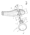
- the implant 1 shown in Figures 1 and 2 is intended to be introduced into a bore 2 formed in the external malleolus or peroneum 3.
- the implant 1 comprises a domed head 4, substantially in the form of a spherical cap and whose radius of curvature is generally equal to that of the outer cheek of the talus of the ankle considered.
- the tail 5 of the implant 1 is provided with external radial flanges 6 whose external diameter d 6 is substantially equal to the internal diameter d 2 of the bore 2.
- two orifices 7 are provided in the tail 5 and are likely to receive a thread of suture 8 or other flexible link.
- a tensile force T which is transmitted by the wire 8 at the tail 5 as represented by the arrow T 'in the figure 2.
- the surgeon introduces the shank 5 in hole 2 without having to exert an effort of thrust on head 4 which may be difficult to access due to the surrounding ligament system.
- the surgeon it suffices for the surgeon to place a wire in one of the orifices 7, to pass the two strands of the wire 8 through the bore 2 by the internal face of the malleolus, then to pull the strands by the external side of the malleolus.
- the traction on the wire 8 has the effect of introducing the tail 5 of the implant 1 into the bore 2 and of pressing the head 4 on the bone.
- the tensile force T exerted on the wire 8 can be intense and directed parallel to the longitudinal axis X 2 of the hole 2, so that the tail is effectively pulled towards the inside of the hole 2.
- the diameters d 2 and d 6 are substantially equal, so that the tail 5 is firmly held in position after it has been put in place.
- the tail 5 is provided with two holes 7 distributed along its axis X 5 , the hole 7 closest to the end 5 a of the tail 5 being used.
- the fact that the tail 5 has several orifices 7 makes it possible to use an orifice 7 relatively close to the end 5 a of the tail 5 and to have such an orifice even when the tail 5 is cut to adapt its length to the thickness e of the malleolus 3.
- the number of holes 7 can be increased if necessary.
- the drilling 2 is carried out by the external face 3 a of the malleolus 3 thanks to the ancillary material shown in FIGS. 3 and 4.
- This material 10 comprises a spacer block 11 intended to be disposed between the tibia T and the talus A d ' an ankle to be fitted in implant 1.
- the block 11 comprises a substantially planar upper surface 12 intended to cooperate with a planar surface created by resection of the distal end of the tibia.
- the lower surface 13 of the block 11 is formed of two flat surfaces 13 a and 13 b inclined with respect to each other by an angle ⁇ , the surfaces 13 a and 13 b being designed to come to bear respectively on corresponding surfaces created by resection of the upper leg of the talus A.
- the surface 12 of the block 11 comprises a housing 14 in the form of C intended to receive a shim 15 whose upper surface 16 is in contact with the lower surface of the tibia T.
- the thickness E of the shim 15 shown in FIG. 3 is such that its upper surface 16 is flush with the upper surface 12 of block 11.
- shims of greater thickness may be used when the distance E 'between the lower surfaces the tibia and the talus is more important than in the configuration shown in Figure 3.
- the block 11 defines a housing 17 for receiving the end 20 of a lug 21 generally in the form of C.
- the end 20 is provided with a bore, not shown, which, in the configuration of FIGS. 3 and 4, is aligned with a bore 18 formed in the block 11 and passing through this block from top to bottom, that is to say connecting the surfaces 12 and 13.
- a screw 19 can be introduced into this bore which is at least partially tapped, which allows the end 20 of the lug 21 to be immobilized inside the housing 17. In practice, the clearance provided when the screw 19 is tightened allows limited pivoting around the axis X 18 of the bore 18.
- the lug 21 supports a tightening system 23 which can be maneuvered by means of a knob 24 and which makes it possible to press the malleolus 3 of the fibula P against a stop 25 formed on an extension 26 of the end 20 of lug 21.
- X 23 denotes the longitudinal axis of these clamping means.
- the clamping means 23 are hollow, so that a forest 30 can be introduced up to the level of the external face 3 a of the malleolus 3 to carry out the drilling 2 from the outside towards the interior of the malleolus 3
- the surgeon can easily target the appropriate part of the malleolus 3 thanks to the clamping means 23 which also constitute a drilling guide for the forest 30.
- the position of the X axis 23 is variable in pivoting around this X axis 18 , which allows the orientation of the bore 2 to be adjusted as best as possible.
- ⁇ the maximum pivot angle of the X axis 23 around the X axis 18 .
- the angle ⁇ is of the order of 10 °.
- the invention has been shown with a total prosthesis ankle, which corresponds to the geometry of the surfaces 12 and 13 of block 11. It is however applicable to a prosthesis partial ankle, without modification of implant 1, the ancillary material then being adapted to the geometry of the anatomical surfaces of articulation between the tibia and the astragalus.
Abstract
Description
L'invention a trait à un implant malléolaire pour une prothèse partielle ou totale de la cheville et à un matériel ancillaire de pose d'un tel implant.The invention relates to a malleolar implant for a partial or total ankle prosthesis and a material procedure for placing such an implant.
Il est connu, par exemple, de EP-A-0 864 304 d'équiper une prothèse de cheville d'un implant malléolaire destiné à venir en appui contre une surface articulaire au niveau de l'astragale, qu'il s'agisse d'une surface naturelle ou d'une surface d'un composant prothétique. Lors d'une intervention sur une cheville, l'accès aux surfaces articulaires internes est limité par le système ligamentaire qui ne permet pas forcément une luxation suffisante de l'articulation. En particulier, l'accès à la surface interne de la malléole péronière peut être insuffisant, ce qui induit des difficultés de positionnement et de mise en place de l'implant, notamment par impaction.It is known, for example, from EP-A-0 864 304 to equip an ankle prosthesis of a malleolar implant intended for come to rest against an articular surface at the talus, whether it is a natural surface or a surface of a prosthetic component. During an intervention on an ankle, access to internal articular surfaces is limited by the ligament system which does not allow necessarily a sufficient dislocation of the joint. In particular, access to the internal surface of the malleolus peroneal may be insufficient, which causes difficulties positioning and placement of the implant, in particular by impaction.
En référence aux modes de réalisations des figures 4 et 5, il est envisagé dans EP-A-0 864 304 d'introduire un implant à partir de la face externe du péroné. Cependant, ceci limite nécessairement la surface de la tête de cet implant, qui doit être inférieure ou égale à la surface de l'orifice prévu dans l'os, de telle sorte qu'elle est forcément de dimensions relativement faibles, sauf à fragiliser sensiblement la malléole.With reference to the embodiments of FIGS. 4 and 5, it is envisaged in EP-A-0 864 304 to introduce an implant from the external side of the fibula. However, this limits necessarily the head surface of this implant, which must be less than or equal to the surface of the hole provided in the bone, so that it is necessarily of dimensions relatively weak, except to appreciably weaken the malleolus.
Pour les raisons qui précèdent, la mise en place des implants malléolaires dans les prothèses connues ne donne pas entièrement satisfaction.For the above reasons, the establishment of malleolar implants in known prostheses do not give completely satisfied.
C'est à ces inconvénients qu'entend plus particulièrement remédier l'invention, en proposant un nouvel implant malléolaire qui peut être mis en place de façon précise, alors même que l'accès à la surface interne de la malléole péronière peut être limité et que sa tête articulaire a des dimensions lui permettant de remplir efficacement sa fonction.It is to these disadvantages that we hear more particularly remedy the invention, by proposing a new malleolar implant which can be set up precisely, so even that access to the internal surface of the peroneal malleolus can be limited and that its joint head has dimensions to effectively perform its function.
Dans cet esprit, l'invention concerne un implant malléolaire comprenant une tête, destinée à venir en appui contre l'astragale ou un composant prothétique astragalien et une queue prévue pour être introduite dans un perçage du péroné, caractérisé en ce que cette queue est pourvue de moyens d'accrochage d'un organe de traction manoeuvrable à partir du côté extérieur du péroné, pour la mise en place de cette queue dans ce perçage.In this spirit, the invention relates to an implant malleolar comprising a head, intended to come to rest against the talus or a talus prosthetic component and a tail intended to be introduced into a bore of the fibula, characterized in that this tail is provided with means for attaching a traction member operable to from the outside of the fibula, for the placement of this tail in this piercing.
Grâce à l'invention, l'implant peut être pré-positionné du côté de la face interne de la malléole péronière et tiré à travers le perçage prévu débouchant dans la malléole, de telle sorte que le chirurgien n'a pas à manipuler précisément l'implant à l'intérieur de l'articulation, c'est-à-dire entre le péroné et le tibia ou entre le péroné et l'astragale. Le chirurgien peut exercer sur l'organe de traction, qui peut être un lien flexible tel qu'un fil de suture, un effort efficace sans être gêné par des os environnants. Il en résulte que la mise en place de la queue de l'implant dans le perçage dans le péroné peut être précise, en particulier du fait que le diamètre extérieur de la queue peut être sensiblement égal au diamètre interne de ce perçage, car l'effort de traction qui peut être exercé par l'extérieur du péroné peut être intense.Thanks to the invention, the implant can be pre-positioned on the side of the inner side of the peroneal malleolus and pulled through the planned hole opening into the malleolus, from so that the surgeon doesn't have to handle it precisely the implant inside the joint, i.e. between the fibula and the tibia or between the fibula and the talus. The surgeon can exercise on the traction organ, which can be a flexible link such as a suture, an effort effective without being hindered by surrounding bones. The result that the placement of the implant tail in the hole in the fibula can be precise, in particular because the outside diameter of the tail can be substantially equal the internal diameter of this hole, because the tensile force which can be exercised from outside the fibula can be intense.
Selon un aspect avantageux de l'invention, la queue est pourvue d'au moins un orifice de passage d'un lien flexible apte à être engagé à travers le perçage. En particulier, la queue peut comprendre plusieurs orifices de passage d'un lien flexible, ces orifices étant répartis sur la longueur de cette queue.According to an advantageous aspect of the invention, the tail is provided with at least one opening for the passage of a flexible link able to be engaged through the hole. In particular, the tail may include more than one link passage flexible, these orifices being distributed over the length of this tail.
Selon un autre aspect avantageux de l'invention, la queue est pourvue de moyens de retenue axiale à l'intérieur du perçage. Ces moyens, qui peuvent être formés par des collerettes radiales externes réparties sur la longueur de la queue, permettent d'immobiliser efficacement la queue à l'intérieur du perçage après qu'elle y a été introduite par traction sur l'organe ou lien flexible.According to another advantageous aspect of the invention, the tail is provided with axial retaining means inside the drilling. These means, which can be formed by flanges external radials distributed over the length of the tail, allow to effectively immobilize the tail inside of the hole after it has been inserted therein by pulling on the flexible organ or link.
L'invention concerne également un matériel ancillaire de pose d'un implant malléolaire tel que précédemment décrit et, plus spécifiquement, un matériel qui comprend un bloc-entretoise, apte à être inséré entre le tibia et l'astragale d'une cheville, et une patte solidaire de ce bloc-entretoise et s'étendant jusqu'au voisinage de la surface externe de la malléole péronière lorsque le bloc-entretoise est en place entre le tibia et l'astragale, cette patte supportant un guide de perçage de la malléole à partir de sa surface externe.The invention also relates to ancillary equipment of placement of a malleolar implant as previously described and, more specifically, equipment which includes a spacer block, able to be inserted between the tibia and the talus an ankle, and a lug secured to this spacer block and extending to the vicinity of the external surface of the peroneal malleolus when the spacer block is in place between the tibia and the talus, this leg supporting a guide piercing the malleolus from its external surface.
Grâce à l'invention, le perçage de la malléole péronière peut être effectué à partir de sa surface externe et en direction de sa surface interne, avec un positionnement relatif déterminé par rapport au tibia et à l'astragale, de telle sorte que la position de l'implant malléolaire en place dans ce perçage est déterminée avec précision par rapport aux surfaces articulaires respectives de l'astragale ou du tibia ou de composants prothétiques correspondants. Le bloc-entretoise peut être prévu pour coopérer avec des surfaces articulaires naturelles du tibia et/ou de l'astragale ou avec des surfaces créées par résection de ces os, dans le cas de la pose d'une prothèse totale de cheville.Thanks to the invention, the drilling of the peroneal malleolus can be made from its external surface and direction of its internal surface, with positioning relative determined with respect to the tibia and the talus, so that the position of the malleolar implant in place in this drilling is determined precisely with respect to respective articular surfaces of the talus or tibia or corresponding prosthetic components. The spacer block may be provided to cooperate with surfaces natural joints of the tibia and / or the talus or with surfaces created by resection of these bones, in the case of the fitting of a total ankle prosthesis.
Selon un aspect avantageux de l'invention, le bloc-entretoise est pourvu d'un logement de réception d'une cale d'épaisseur adaptée à l'écart entre les surfaces inférieure du tibia et supérieure de l'astragale. Cet aspect de l'invention permet de maintenir un écart, correspondant à celui qui sera ultérieurement crée par des éléments prothétiques montés en partie basse du tibia et en partie supérieure de l'astragale, lors de la détermination de la position de l'implant malléolaire.According to an advantageous aspect of the invention, the spacer block is provided with a wedge receiving housing thickness adapted to the distance between the lower surfaces of the tibia and superior of the talus. This aspect of the invention allows to maintain a gap, corresponding to that which will be subsequently created by prosthetic elements fitted in the lower part of the tibia and in the upper part of the talus, when determining the implant position malleolar.
Selon un autre aspect avantageux de l'invention, la patte est articulée sur le bloc-entretoise, avec une possibilité de pivotement limitée. Ceci permet d'ajuster la position du guide de perçage de la malléole autour de l'axe de pivotement de la patte par rapport au bloc-entretoise. Dans ce cas, le bloc-entretoise et la patte sont avantageusement pourvus d'orifices de passage d'un axe de pivotement commun.According to another advantageous aspect of the invention, the tab is articulated on the spacer block, with a possibility of limited pivoting. This allows you to adjust the position of the guide of the malleolus around the pivot axis of the tab relative to the spacer block. In this case, the spacer block and the tab are advantageously provided with orifices passage of a common pivot axis.
On peut en outre prévoir que le guide de perçage est associé à un dispositif de serrage de la malléole contre une surface d'appui formée sur la patte ou le bloc-entretoise. Ceci permet une immobilisation ferme de la malléole péronière lors de son perçage et assure ainsi la précision de l'opération de perçage.It can also be provided that the drilling guide is associated with a malleolus clamping device against a bearing surface formed on the tab or the spacer block. This allows a firm immobilization of the peroneal malleolus during its drilling and thus ensures the precision of the operation drilling.
L'invention sera mieux comprise et d'autres avantages de celle-ci apparaítront plus clairement à la lumière de la description qui va suivre d'un mode de réalisation d'un implant malléolaire et de son matériel ancillaire de pose conformes à l'invention, donnée uniquement à titre d'exemple et faite en référence aux dessins annexés dans lesquels :
- la figure 1 est une vue en perspective d'un implant conforme à l'invention ;
- la figure 2 est une vue en perspective de l'implant de la figure 1 en cours de mise en place dans une malléole péronière représentée avec arrachement ;
- la figure 3 est une représentation schématique de principe, avec arrachements partiels, d'un matériel ancillaire de pose de l'implant de la figure 1 en cours d'utilisation et
- la figure 4 est une vue en perspective par en dessous du matériel de la figure 1.
- Figure 1 is a perspective view of an implant according to the invention;
- Figure 2 is a perspective view of the implant of Figure 1 being placed in a peroneal malleolus shown with cutaway;
- FIG. 3 is a schematic representation of the principle, with partial cutaway, of ancillary equipment for placing the implant of FIG. 1 in use and
- FIG. 4 is a perspective view from below of the equipment of FIG. 1.
L'implant 1 représenté aux figures 1 et 2 est destiné à
être introduit dans un perçage 2 ménagé dans la malléole
externe ou péronière 3. L'implant 1 comprend une tête bombée
4, sensiblement selon une forme de calotte sphérique et dont
le rayon de courbure est globalement égal à celui de la joue
externe de l'astragale de la cheville considérée. La queue 5
de l'implant 1 est pourvue de collerettes radiales externes
6 dont le diamètre extérieur d6 est sensiblement égale au
diamètre interne d2 du perçage 2.The
Conformément à l'invention, deux orifices 7 sont prévus
dans la queue 5 et sont susceptibles de recevoir un fil de
suture 8 ou un autre lien flexible. Lorsqu'un tel fil est
engagé dans l'un des orifices 7, il est possible d'exercer sur
le fil 8, un effort de traction T qui est transmis par le fil
8 à la queue 5 comme représenté par la flèche T' à la figure
2. Ainsi, en tirant sur le fil 8, le chirurgien introduit la
queue 5 dans le perçage 2 sans devoir exercer un effort de
poussée sur la tête 4 qui peut être difficilement accessible
du fait du système ligamentaire environnant.According to the invention, two
En d'autres termes, il suffit au chirurgien de placer un
fil dans un des orifices 7, de passer les deux brins du fil
8 dans le perçage 2 par la face interne de la malléole, puis
de tirer les brins par le côté externe de la malléole. La
traction sur le fil 8 a pour effet d'introduire la queue 5 de
l'implant 1 dans le perçage 2 et de plaquer la tête 4 sur
l'os. L'effort de traction T exercé sur le fil 8 peut être
intense et dirigé parallèlement à l'axe longitudinale X2 du
perçage 2, de telle sorte que la queue est efficacement tirée
vers l'intérieur du perçage 2. En particulier, compte tenu de
la direction et de l'intensité de l'effort de traction T, on
peut prévoir que les diamètres d2 et d6 sont sensiblement
égaux, de telle sorte que la queue 5 est fermement maintenue
en position après sa mise en place.In other words, it suffices for the surgeon to place a wire in one of the
La queue 5 est pourvue de deux perçages 7 répartis selon
son axe X5, le perçage 7 le plus proche de l'extrémité 5a de
la queue 5 étant utilisé. Le fait que la queue 5 comporte
plusieurs orifices 7 permet d'utiliser un orifice 7 relativement
proche de l'extrémité 5a de la queue 5 et de disposer
d'un tel orifice y compris lorsque la queue 5 est sectionnée
pour adapter sa longueur à l'épaisseur e de la malléole 3.
Bien entendu, le nombre de perçages 7 peut être augmenté si
nécessaire.The
Le perçage 2 est réalisé par la face externe 3a de la
malléole 3 grâce au matériel ancillaire représenté aux figures
3 et 4. Ce matériel 10 comprend un bloc-entretoise 11 prévu
pour être disposé entre le tibia T et l'astragale A d'une
cheville à équiper en implant 1. Le bloc 11 comprend une
surface supérieure 12 sensiblement plane destinée à coopérer
avec une surface plane créée par résection de la l'extrémité
distale du tibia. La surface inférieure 13 du bloc 11 est
formée de deux surfaces planes 13a et 13b inclinées l'une par
rapport à l'autre d'un angle α, les surfaces 13a et 13b étant
prévues pour venir respectivement en appui sur des surfaces
correspondantes créées par résection de la patte supérieure
de l'astragale A.The
La surface 12 du bloc 11 comprend un logement 14 en forme
de C destiné à recevoir une cale 15 dont la surface supérieure
16 est en contact avec la surface inférieure du tibia T.
L'épaisseur E de la cale 15 représentée à la figure 3 est
telle que sa surface supérieure 16 est affleurante avec la
surface supérieure 12 du bloc 11.The
Cependant, des cales d'épaisseur plus importante peuvent être utilisées lorsque l'écart E' entre les surfaces inférieure du tibia et supérieure de l'astragale est plus important que dans la configuration représentée à la figure 3.However, shims of greater thickness may be used when the distance E 'between the lower surfaces the tibia and the talus is more important than in the configuration shown in Figure 3.
Le bloc 11 définit un logement 17 de réception de
l'extrémité 20 d'une patte 21 globalement en forme de C.
L'extrémité 20 est pourvue d'un perçage non représenté qui,
dans la configuration des figures 3 et 4, est aligné avec un
perçage 18 ménagé dans le bloc 11 et traversant ce bloc de
haut en bas, c'est-à-dire reliant les surfaces 12 et 13. Une
vis 19 peut être introduite dans ce perçage qui est au moins
partiellement taraudé, ce qui permet d'immobiliser l'extrémité
20 de la patte 21 à l'intérieur du logement 17. En pratique,
le jeu ménagé lors du serrage de la vis 19 autorise un
pivotement limité autour de l'axe X18 du perçage 18.The
Au niveau de son extrémité 22 opposée à l'extrémité 20,
la patte 21 supporte un système de serrage 23 manoeuvrable
grâce à une mollette 24 et permettant de plaquer la malléole
3 du péroné P contre une butée 25 formée sur une extension 26
de l'extrémité 20 de la patte 21. On note X23 l'axe longitudinal
de ces moyens de serrage. Les moyens de serrage 23 sont
creux, de telle sorte qu'un forêt 30 peut être introduit
jusqu'au niveau de la face externe 3a de la malléole 3 pour
réaliser le perçage 2 depuis l'extérieur vers l'intérieur de
la malléole 3. Ainsi, le chirurgien peut aisément viser la
partie adéquate de la malléole 3 grâce aux moyens de serrage
23 qui constituent également un guide de perçage pour le forêt
30.At its
Comme la patte 21 est susceptible de pivoter autour de
l'axe X18, la position de l'axe X23 est variable en pivotement
autour de cet axe X18, ce qui permet d'ajuster au mieux
l'orientation du perçage 2 en fonction de la géométrie exacte
de la malléole 3. On note β l'angle de pivotement maximum de
l'axe X23 autour de l'axe X18. En pratique, l'angle β est de
l'ordre de 10°.As the
Grâce au matériel 10, on peut donc former, par l'extérieur,
un perçage 2 permettant une implantation rapide et
efficace de l'implant 1.Thanks to the
Lorsque des cales 15 de hauteur supérieure à celles
représentées à la figure 2 sont utilisé, il est possible de
prévoir qu'elles viennent en recouvrement du perçage 18 car
la vis 19 est mise en place avant le positionnement de la cale
15 qui est effectué en cours d'opération en fonction de
l'écart E'.When shims 15 of height greater than those
shown in Figure 2 are used, it is possible to
provide that they cover the
L'invention a été représentée avec une prothèse totale
de cheville, ce qui correspond à la géométrie des surfaces 12
et 13 du bloc 11. Elle est cependant applicable à une prothèse
partielle de cheville, sans modification de l'implant 1, le
matériel ancillaire étant alors adapté à la géométrie des
surfaces anatomiques d'articulation entre le tibia et
l'astragale.The invention has been shown with a total prosthesis
ankle, which corresponds to the geometry of the
Claims (10)
Priority Applications (1)
| Application Number | Priority Date | Filing Date | Title |
|---|---|---|---|
| EP03027583A EP1398009B1 (en) | 1999-08-05 | 2000-08-03 | Ancillary equipment for inserting a malleolar implant for a partial or total ankle prosthesis and implant suitable for being inserted with this equipment |
Applications Claiming Priority (2)
| Application Number | Priority Date | Filing Date | Title |
|---|---|---|---|
| FR9910340 | 1999-08-05 | ||
| FR9910340A FR2797178B1 (en) | 1999-08-05 | 1999-08-05 | MALLEOLAR IMPLANT FOR PARTIAL OR TOTAL ANKLE PROSTHESIS AND ANCILLARY MATERIAL FOR PLACING SUCH AN IMPLANT |
Related Child Applications (1)
| Application Number | Title | Priority Date | Filing Date |
|---|---|---|---|
| EP03027583A Division EP1398009B1 (en) | 1999-08-05 | 2000-08-03 | Ancillary equipment for inserting a malleolar implant for a partial or total ankle prosthesis and implant suitable for being inserted with this equipment |
Publications (2)
| Publication Number | Publication Date |
|---|---|
| EP1074230A1 true EP1074230A1 (en) | 2001-02-07 |
| EP1074230B1 EP1074230B1 (en) | 2004-09-22 |
Family
ID=9549040
Family Applications (2)
| Application Number | Title | Priority Date | Filing Date |
|---|---|---|---|
| EP00420173A Expired - Lifetime EP1074230B1 (en) | 1999-08-05 | 2000-08-03 | Malleolar implant for a partial or total ankle prosthesis and ancillary equipment for fitting such an implant |
| EP03027583A Expired - Lifetime EP1398009B1 (en) | 1999-08-05 | 2000-08-03 | Ancillary equipment for inserting a malleolar implant for a partial or total ankle prosthesis and implant suitable for being inserted with this equipment |
Family Applications After (1)
| Application Number | Title | Priority Date | Filing Date |
|---|---|---|---|
| EP03027583A Expired - Lifetime EP1398009B1 (en) | 1999-08-05 | 2000-08-03 | Ancillary equipment for inserting a malleolar implant for a partial or total ankle prosthesis and implant suitable for being inserted with this equipment |
Country Status (6)
| Country | Link |
|---|---|
| US (5) | US6488712B1 (en) |
| EP (2) | EP1074230B1 (en) |
| AT (2) | ATE276716T1 (en) |
| DE (2) | DE60013982T2 (en) |
| ES (2) | ES2226750T3 (en) |
| FR (1) | FR2797178B1 (en) |
Cited By (1)
| Publication number | Priority date | Publication date | Assignee | Title |
|---|---|---|---|---|
| US7025790B2 (en) | 2002-06-27 | 2006-04-11 | Concepts In Medicine Iii, L.L.C. | Ankle joint prosthesis and its method of implantation |
Families Citing this family (71)
| Publication number | Priority date | Publication date | Assignee | Title |
|---|---|---|---|---|
| FR2768613B1 (en) * | 1997-09-23 | 1999-12-17 | Tornier Sa | KNEE PROSTHESIS WITH ROTATABLE PLATFORM |
| FR2797178B1 (en) * | 1999-08-05 | 2002-02-22 | Tornier Sa | MALLEOLAR IMPLANT FOR PARTIAL OR TOTAL ANKLE PROSTHESIS AND ANCILLARY MATERIAL FOR PLACING SUCH AN IMPLANT |
| US6663669B1 (en) * | 1999-10-22 | 2003-12-16 | Mark A Reiley | Ankle replacement system |
| FR2826859B1 (en) * | 2001-07-09 | 2003-09-19 | Tornier Sa | ANCILLARY OF LAYING OF A HUMERAL COMPONENT OF ELBOW PROSTHESIS |
| FR2826860B1 (en) * | 2001-07-09 | 2004-03-05 | Tornier Sa | ANCILLARY OF POSITION OF A CUBITAL COMPONENT AND / OR A RADIAL COMPONENT OF ELBOW PROSTHESIS |
| FR2827500B1 (en) * | 2001-07-17 | 2004-04-02 | Tornier Sa | PLATE OF OSTEOSYNTHESIS OF THE UPPER END OF THE HUMERUS |
| FR2848183B1 (en) * | 2002-12-10 | 2006-01-27 | Tornier Sa | STERILE CONDITIONING METHOD OF A POLYETHYLENE PROTHETIC IMPLANT |
| FR2850010B1 (en) * | 2003-01-17 | 2005-12-02 | Tornier Sa | ANCILLARY FOR THE INSTALLATION OF A PROTHETIC COTYL FOR A HIP PROSTHESIS |
| US7887544B2 (en) | 2003-03-10 | 2011-02-15 | Tornier Sas | Ancillary tool for positioning a glenoid implant |
| FR2854792B1 (en) * | 2003-05-12 | 2005-09-09 | Tornier Sa | GAME OF PROTHETIC ELEMENTS FOR A TIBIAL PROTHETIC SET |
| FR2855397B1 (en) | 2003-05-28 | 2005-07-15 | Tornier Sa | ELBOW PROSTHESIS |
| WO2005048872A2 (en) * | 2003-06-27 | 2005-06-02 | Advanced Bio Surfaces, Inc. | System and method for ankle arthroplasty |
| US8092547B2 (en) * | 2004-02-10 | 2012-01-10 | Tornier, Inc. | Subtalar implant assembly |
| FR2865928B1 (en) | 2004-02-10 | 2006-03-17 | Tornier Sa | SURGICAL DEVICE FOR IMPLANTATION OF A TOTAL HIP PROSTHESIS |
| US7678153B2 (en) * | 2004-05-04 | 2010-03-16 | Biopro, Inc. | Subtalar implant |
| US20060041315A1 (en) * | 2004-05-04 | 2006-02-23 | Biopro, Inc. | Subtalar implant |
| US7641698B1 (en) | 2004-06-04 | 2010-01-05 | Biomet Manufacturing Corp. | Modular hip joint implant |
| US7179259B1 (en) * | 2004-06-04 | 2007-02-20 | Biomet Manufacturing Corp. | Instrument assembly for lateral implant |
| EP1607069B1 (en) | 2004-06-15 | 2009-12-23 | Tornier | Inverse-type total shoulder prosthesis |
| US8303665B2 (en) | 2004-06-15 | 2012-11-06 | Tornier Sas | Glenoidal component, set of such components and shoulder prosthesis incorporating such a glenoidal component |
| FR2871368B1 (en) | 2004-06-15 | 2006-08-25 | Tornier Sas | SET OF HUMERAL COMPONENTS FOR TOTAL SHOULDER PROSTHESIS |
| US20050288792A1 (en) * | 2004-06-23 | 2005-12-29 | Landes Mark D | Modular ankle prosthesis and associated method |
| FR2872025B1 (en) * | 2004-06-28 | 2006-08-25 | Tornier Sas | PROSTHESIS OF SHOULDER OR HIP |
| FR2881340B1 (en) * | 2005-02-01 | 2008-01-11 | Tornier Sas | HUMERAL NUTS |
| CA2601090C (en) | 2005-03-14 | 2013-08-20 | Inbone Technologies, Inc. | Ankle replacement system |
| FR2884407B1 (en) * | 2005-04-13 | 2007-05-25 | Tornier Sas | SURGICAL DEVICE FOR IMPLANTATION OF A PARTIAL OR TOTAL KNEE PROSTHESIS |
| FR2884408B1 (en) * | 2005-04-13 | 2007-05-25 | Tornier Sas | SURGICAL DEVICE FOR IMPLANTATION OF A PARTIAL OR TOTAL KNEE PROSTHESIS |
| US7468077B2 (en) * | 2005-08-02 | 2008-12-23 | Tornier Sas | Patellar retractor and method of surgical procedure on knee |
| FR2896404B1 (en) * | 2006-01-24 | 2008-02-29 | Tornier Sas | SURGICAL INSTRUMENTATION ASSEMBLY FOR POSTING AN ANKLE PROSTHESIS |
| FR2896684B1 (en) * | 2006-02-01 | 2008-09-26 | Tornier Soc Par Actions Simplifiee | TIBIAL IMPLANT WITH OFFSET SHAFT |
| FR2899790B1 (en) | 2006-04-13 | 2008-06-13 | Tornier Sas | GLENOIDAL COMPONENT FOR TOTAL SHOULDER PROSTHESIS, SET OF SUCH COMPONENTS, AND TOTAL SHOULDER PROSTHESIS COMPRISING SUCH A COMPONENT |
| FR2900045B1 (en) | 2006-04-21 | 2009-01-16 | Tornier Sas | PROSTHESIS OF SHOULDER OR HIP |
| FR2906999B1 (en) | 2006-10-13 | 2009-06-05 | Tornier Sas | PROTHETIC SET OF ANKLE |
| GB2445146C (en) * | 2006-12-23 | 2016-03-23 | Corin Ltd | Improvements in and relating to an ankle prosthesis |
| EP2178468B1 (en) * | 2007-08-01 | 2016-06-22 | Jeffrey Halbrecht | System for patella tendon realignment |
| US20100131069A1 (en) * | 2007-08-01 | 2010-05-27 | Jeffrey Halbrecht | Method and system for patella tendon realignment |
| US20090105840A1 (en) * | 2007-10-18 | 2009-04-23 | Inbone Technologies, Inc. | Fibular stiffener and bony defect replacer |
| US8052755B2 (en) * | 2008-05-09 | 2011-11-08 | Remi Sciences, Inc. | Ulnar head prosthesis system |
| EP2656797A3 (en) | 2008-07-17 | 2014-02-12 | Smith & Nephew, Inc. | Anchor |
| CA2954249C (en) * | 2008-08-01 | 2017-11-07 | Skeletal Dynamics, Llc | Internal joint stabilizer device, system and method of use |
| US10327817B2 (en) | 2008-08-01 | 2019-06-25 | Skeletal Dynamics Llc | Internal joint stabilizer device, system and method of use |
| US9017334B2 (en) | 2009-02-24 | 2015-04-28 | Microport Orthopedics Holdings Inc. | Patient specific surgical guide locator and mount |
| US8808303B2 (en) | 2009-02-24 | 2014-08-19 | Microport Orthopedics Holdings Inc. | Orthopedic surgical guide |
| US8808297B2 (en) | 2009-02-24 | 2014-08-19 | Microport Orthopedics Holdings Inc. | Orthopedic surgical guide |
| US10349980B2 (en) | 2009-08-27 | 2019-07-16 | The Foundry, Llc | Method and apparatus for altering biomechanics of the shoulder |
| US9861408B2 (en) | 2009-08-27 | 2018-01-09 | The Foundry, Llc | Method and apparatus for treating canine cruciate ligament disease |
| US9668868B2 (en) | 2009-08-27 | 2017-06-06 | Cotera, Inc. | Apparatus and methods for treatment of patellofemoral conditions |
| EP2781197B8 (en) | 2009-08-27 | 2018-06-27 | The Foundry, LLC | Apparatus for force redistribution in articular joints |
| US9278004B2 (en) | 2009-08-27 | 2016-03-08 | Cotera, Inc. | Method and apparatus for altering biomechanics of the articular joints |
| WO2012006434A1 (en) * | 2010-07-07 | 2012-01-12 | Global Orthopaedic Solutions Llc | Malleolar replacement devices |
| FR2966343B1 (en) | 2010-10-22 | 2012-12-07 | Tornier Sa | SET OF GLENOIDIAN COMPONENTS OF SHOULDER PROSTHESIS |
| AU2016244327B2 (en) * | 2010-12-20 | 2018-04-05 | Microport Orthopedics Holdings Inc. | Orthopedic surgical guide |
| US8979937B2 (en) | 2011-09-27 | 2015-03-17 | Linares Medical Devices, Llc | Implantable ankle joint assembly with spherical inter-support |
| US9468466B1 (en) | 2012-08-24 | 2016-10-18 | Cotera, Inc. | Method and apparatus for altering biomechanics of the spine |
| US9480571B2 (en) | 2012-12-27 | 2016-11-01 | Wright Medical Technology, Inc. | Ankle replacement system and method |
| US9918724B2 (en) | 2012-12-27 | 2018-03-20 | Wright Medical Technology, Inc. | Ankle replacement system and method |
| US10080573B2 (en) | 2012-12-27 | 2018-09-25 | Wright Medical Technology, Inc. | Ankle replacement system and method |
| AU2013270628B2 (en) | 2012-12-27 | 2015-02-05 | Wright Medical Technology, Inc. | Ankle replacement system and method |
| US9974588B2 (en) | 2012-12-27 | 2018-05-22 | Wright Medical Technology, Inc. | Ankle replacement system and method |
| WO2014152535A1 (en) | 2013-03-14 | 2014-09-25 | Wright Medical Technology, Inc. | Ankle replacement system and method |
| BR112015021018A2 (en) | 2013-03-06 | 2017-07-18 | Smith & Nephew Inc | micro-anchor |
| US9949839B2 (en) | 2013-03-13 | 2018-04-24 | Wright Medical Technology, Inc. | Revision implant augments, systems, and methods |
| JP6573908B2 (en) | 2014-05-12 | 2019-09-11 | インテグラ・ライフサイエンシーズ・コーポレイションIntegra LifeSciences Corporation | Total joint replacement prosthesis |
| US10575968B2 (en) | 2014-05-16 | 2020-03-03 | Howmedica Osteonics Corp. | Guides for fracture system |
| US9681960B2 (en) | 2014-05-16 | 2017-06-20 | Howmedica Osteonics Corp. | Guides for fracture system |
| US20150374503A1 (en) * | 2014-06-30 | 2015-12-31 | Bacterin International, Inc. | Implant for fusion between adjacent bone bodies |
| CN105726135B (en) * | 2016-01-28 | 2018-10-26 | 佛山市乙太医疗用品有限公司 | A kind of elbow joint rotation center guider applied in clinical operation |
| EP4353160A2 (en) | 2016-03-23 | 2024-04-17 | Wright Medical Technology, Inc. | Fixation apparatus and method for total ankle replacement |
| US10136998B2 (en) | 2016-08-30 | 2018-11-27 | Wright Medical Technology, Inc. | Revision total ankle implants |
| EP4084711A4 (en) | 2020-01-02 | 2024-01-03 | Zkr Orthopedics Inc | Patella tendon realignment implant with changeable shape |
| US11872137B2 (en) | 2021-06-15 | 2024-01-16 | Wright Medical Technology, Inc. | Unicompartmental ankle prosthesis |
Citations (6)
| Publication number | Priority date | Publication date | Assignee | Title |
|---|---|---|---|---|
| US3987500A (en) * | 1976-01-28 | 1976-10-26 | Schlein Allen P | Surgically implantable total ankle prosthesis |
| US4159716A (en) * | 1977-10-17 | 1979-07-03 | Borchers Clinton H | Method of compressing and realigning bone structures to correct splay foot |
| US4235428A (en) * | 1979-03-15 | 1980-11-25 | Davis Jack H | Bone transfixation pin guide |
| FR2700462A1 (en) * | 1993-01-19 | 1994-07-22 | Medimplant | Guide instrument for making holes for foot joint implant |
| US5601550A (en) * | 1994-10-25 | 1997-02-11 | Esser; Rene D. | Pelvic pin guide system for insertion of pins into iliac bone |
| EP0864304A1 (en) * | 1997-03-10 | 1998-09-16 | Tornier Sa | Ankle prosthesis |
Family Cites Families (83)
| Publication number | Priority date | Publication date | Assignee | Title |
|---|---|---|---|---|
| US2393831A (en) * | 1942-12-29 | 1946-01-29 | Stader Otto | Bone splint |
| US3779654A (en) * | 1971-08-06 | 1973-12-18 | R Horne | Artificial joint |
| US4069518A (en) * | 1976-08-31 | 1978-01-24 | Groth Jr Harry E | Total ankle prosthesis |
| GB1579773A (en) * | 1977-07-18 | 1980-11-26 | Nat Res Dev | Endoprosthetic bone joint devices |
| US4257411A (en) * | 1979-02-08 | 1981-03-24 | Cho Kenneth O | Cruciate ligament surgical drill guide |
| US4644943A (en) * | 1984-07-20 | 1987-02-24 | Regents Of The University Of Minnesota | Bone fixation device |
| US4722331A (en) * | 1985-09-03 | 1988-02-02 | Fox James M | Orthopaedic tool guide |
| IT1221530B (en) * | 1987-07-20 | 1990-07-12 | Italpres Snc Di Fregni Bruno & | PRECISION PERFORATION EQUIPMENT OF THE FEMOR AND TIBIA FOR THE INSTALLATION OF THE KNEE JOINT OF THE CRUSADED FRONT AND REAR PROSTHETIC LIGAMENTS |
| US5197986A (en) * | 1990-04-11 | 1993-03-30 | Mikhail Michael W E | Recessed patellar prosthesis |
| US5236445A (en) * | 1990-07-02 | 1993-08-17 | American Cyanamid Company | Expandable bone anchor and method of anchoring a suture to a bone |
| US5258016A (en) * | 1990-07-13 | 1993-11-02 | American Cyanamid Company | Suture anchor and driver assembly |
| FR2669213A1 (en) | 1990-11-19 | 1992-05-22 | Tornier Sa | PARTIALLY CEMENTED FEMALE PROSTHESIS. |
| US5354298A (en) * | 1991-03-22 | 1994-10-11 | United States Surgical Corporation | Suture anchor installation system |
| US5480403A (en) * | 1991-03-22 | 1996-01-02 | United States Surgical Corporation | Suture anchoring device and method |
| FR2681240A1 (en) | 1991-09-12 | 1993-03-19 | Tornier Sa | TOTAL WRIST PROSTHESIS. |
| FR2684290B1 (en) | 1991-11-29 | 1994-01-21 | Tornier Ets | KNEE PROSTHESIS. |
| FR2685633B1 (en) | 1991-12-27 | 1998-02-27 | Tornier Sa | MODULAR HUMER PROSTHESIS. |
| FR2691357A1 (en) | 1992-05-25 | 1993-11-26 | Tornier Sa | Total prosthesis for the metacarpophalangeal joint. |
| US5312409A (en) * | 1992-06-01 | 1994-05-17 | Mclaughlin Robert E | Drill alignment guide |
| US5176682A (en) * | 1992-06-01 | 1993-01-05 | Chow James C Y | Surgical implement |
| US5306290A (en) * | 1993-02-12 | 1994-04-26 | Mitek Surgical Products, Inc. | Suture button |
| US5380334A (en) * | 1993-02-17 | 1995-01-10 | Smith & Nephew Dyonics, Inc. | Soft tissue anchors and systems for implantation |
| FR2703240B1 (en) | 1993-03-30 | 1995-06-02 | Tornier Sa | Elastically deformable acetabular prosthesis. |
| FR2705226B1 (en) | 1993-05-17 | 1995-07-07 | Tornier Sa | Spine fixator to maintain a spine. |
| US5423860A (en) * | 1993-05-28 | 1995-06-13 | American Cyanamid Company | Protective carrier for suture anchor |
| FR2709412B1 (en) | 1993-09-01 | 1995-11-24 | Tornier Sa | Screw for lumbo-sacral fixator. |
| FR2711505B1 (en) | 1993-10-25 | 1995-12-29 | Tornier Sa | Device for synthesizing fractures of the upper end of the femur. |
| US5403321A (en) * | 1993-12-15 | 1995-04-04 | Smith & Nephew Richards Inc. | Radiolucent drill guide |
| US5486197A (en) * | 1994-03-24 | 1996-01-23 | Ethicon, Inc. | Two-piece suture anchor with barbs |
| FR2724553B1 (en) | 1994-09-15 | 1996-12-20 | Tornier Sa | EXTERNAL OR INTERNAL FIXER FOR THE REPAIR OF FRACTURES OR ARTHROPLASTIES OF THE SKELETON |
| US5464427A (en) * | 1994-10-04 | 1995-11-07 | Synthes (U.S.A.) | Expanding suture anchor |
| US5674224A (en) * | 1994-11-18 | 1997-10-07 | Howell; Stephen M. | Bone mulch screw assembly for endosteal fixation of soft tissue grafts and method for using same |
| FR2727002B1 (en) | 1994-11-18 | 1997-01-03 | Tornier Sa | HUMERAL PROSTHESIS IN SPHERE |
| FR2728159B1 (en) | 1994-12-16 | 1997-06-27 | Tornier Sa | ELASTIC DISC PROSTHESIS |
| US5766259A (en) * | 1995-03-14 | 1998-06-16 | Sammarco; Giacomo J. | Total ankle prosthesis and method |
| FR2735356B1 (en) | 1995-06-16 | 1997-11-28 | Tornier Sa | COTYLOID IMPLANT, IN PARTICULAR FOR ILIAC JOINT CAVITY |
| FR2741796B1 (en) | 1995-11-30 | 1998-03-27 | Tornier Sa | DEVICE FOR FIXING A PROSTHESIS AND PARTICULARLY A GLENOIDAL PROSTHESIS OF OMOPLATE |
| FR2743716B1 (en) | 1996-01-23 | 1998-04-10 | Tornier Sa | TIBIAL PROSTHESIS |
| FR2747302B1 (en) | 1996-04-11 | 1998-09-11 | Tornier Sa | ANKLE PROSTHESIS |
| FR2750037B1 (en) | 1996-06-25 | 1998-11-27 | Tornier Sa | MONOBLOCK SHOULDER PROSTHESIS |
| FR2751868B1 (en) | 1996-08-02 | 1999-04-16 | Tornier Sa | ADJUSTED PROSTHESIS OF THE SUPERIOR END OF THE HUMERUS |
| DE69734606T2 (en) * | 1996-11-21 | 2006-08-03 | Ethicon, Inc. | DEVICE FOR FIXING BODY-FREE OR ARTIFICIAL TENANTS IN BONES |
| FR2758455B1 (en) | 1997-01-23 | 1999-08-06 | Tornier Sa | TOTAL ELBOW PROSTHESIS |
| FR2760353B1 (en) * | 1997-03-10 | 1999-07-02 | Tornier Sa | ANKLE PROSTHESIS |
| FR2768330B1 (en) | 1997-09-12 | 2000-01-21 | Tornier Sa | HUMERAL PROSTHESIS WITH INDEXED SPHERE |
| FR2768613B1 (en) | 1997-09-23 | 1999-12-17 | Tornier Sa | KNEE PROSTHESIS WITH ROTATABLE PLATFORM |
| FR2768922B1 (en) | 1997-10-01 | 2000-01-14 | Tornier Sa | PROSTHESIS FOR BEING ANCHORED IN A LONG BONE |
| FR2769495B1 (en) | 1997-10-14 | 1999-12-31 | Michel Timoteo | KNEE PROSTHESIS |
| FR2769494B1 (en) | 1997-10-14 | 1999-12-31 | Michel Timoteo | FEMALE PART FOR KNEE PROSTHESIS |
| US5931837A (en) * | 1997-12-09 | 1999-08-03 | University Of Iowa Research Foundation | Method and apparatus for external fixation of an ankle |
| FR2772259B1 (en) | 1997-12-12 | 2000-03-03 | Tornier Sa | IMPROVEMENTS IN TOTAL KNEE PROSTHESES COMPRISING A FEMORAL ELEMENT AND A TIBIAL PLATE |
| FR2775586B1 (en) | 1998-03-03 | 2000-06-30 | Tornier Sa | MODULAR ACETABULAR OR COTYLOID IMPLANT |
| FR2777447B1 (en) | 1998-04-21 | 2000-07-28 | Tornier Sa | REVERSIBLE FIXATION DEVICE FOR PLACING AN IMPLANT IN THE BONE |
| FR2777442B1 (en) | 1998-04-21 | 2000-07-28 | Tornier Sa | REVERSIBLE EXPANSION SUTURE ANCHOR |
| FR2777443B1 (en) | 1998-04-21 | 2000-06-30 | Tornier Sa | ANCILLARY FOR THE PLACEMENT AND REMOVAL OF AN IMPLANT AND MORE PARTICULARLY A SUTURE ANCHOR |
| FR2782913B1 (en) * | 1998-09-04 | 2000-11-10 | Perice Ramon Viladot | IMPLANT FOR FLAT FOOT |
| US6086591A (en) * | 1999-01-29 | 2000-07-11 | Smith & Nephew, Inc. | Soft tissue anchor |
| FR2793404B1 (en) | 1999-05-14 | 2001-09-14 | Tornier Sa | ELBOW PROSTHESIS |
| FR2794641B1 (en) | 1999-06-09 | 2001-11-23 | Tornier Sa | HUMER PROSTHESIS |
| FR2797178B1 (en) * | 1999-08-05 | 2002-02-22 | Tornier Sa | MALLEOLAR IMPLANT FOR PARTIAL OR TOTAL ANKLE PROSTHESIS AND ANCILLARY MATERIAL FOR PLACING SUCH AN IMPLANT |
| FR2826859B1 (en) | 2001-07-09 | 2003-09-19 | Tornier Sa | ANCILLARY OF LAYING OF A HUMERAL COMPONENT OF ELBOW PROSTHESIS |
| FR2826860B1 (en) | 2001-07-09 | 2004-03-05 | Tornier Sa | ANCILLARY OF POSITION OF A CUBITAL COMPONENT AND / OR A RADIAL COMPONENT OF ELBOW PROSTHESIS |
| FR2827500B1 (en) | 2001-07-17 | 2004-04-02 | Tornier Sa | PLATE OF OSTEOSYNTHESIS OF THE UPPER END OF THE HUMERUS |
| FR2831426B1 (en) | 2001-10-30 | 2004-07-16 | Tornier Sa | JOINT IMPLANT AND KNEE PROSTHESIS INCORPORATING SUCH AN IMPLANT |
| US6685706B2 (en) * | 2001-11-19 | 2004-02-03 | Triage Medical, Inc. | Proximal anchors for bone fixation system |
| FR2835425B1 (en) | 2002-02-04 | 2004-04-09 | Tornier Sa | PROSTHETIC ELEMENT COMPRISING TWO COMPONENTS AND METHOD FOR ASSEMBLING SUCH A PROSTHETIC ELEMENT |
| FR2836039B1 (en) | 2002-02-15 | 2004-10-01 | Tornier Sa | GLENOIDAL COMPONENT OF SHOULDER PROSTHESIS AND TOTAL SHOULDER PROSTHESIS INCORPORATING SUCH COMPONENT |
| FR2841768B1 (en) | 2002-07-05 | 2005-05-06 | Tornier Sa | SHOULDER OR HIP PROSTHESIS FACILITATING ABDUCTION |
| FR2848183B1 (en) | 2002-12-10 | 2006-01-27 | Tornier Sa | STERILE CONDITIONING METHOD OF A POLYETHYLENE PROTHETIC IMPLANT |
| FR2850010B1 (en) | 2003-01-17 | 2005-12-02 | Tornier Sa | ANCILLARY FOR THE INSTALLATION OF A PROTHETIC COTYL FOR A HIP PROSTHESIS |
| US7887544B2 (en) | 2003-03-10 | 2011-02-15 | Tornier Sas | Ancillary tool for positioning a glenoid implant |
| FR2854792B1 (en) | 2003-05-12 | 2005-09-09 | Tornier Sa | GAME OF PROTHETIC ELEMENTS FOR A TIBIAL PROTHETIC SET |
| FR2855397B1 (en) | 2003-05-28 | 2005-07-15 | Tornier Sa | ELBOW PROSTHESIS |
| FR2859099B1 (en) | 2003-08-25 | 2006-01-06 | Tornier Sa | GLENOIDAL COMPONENT OF SHOULDER PROSTHESIS AND TOTAL SHOULDER PROSTHESIS INCORPORATING SUCH COMPONENT |
| FR2863865B1 (en) | 2003-12-19 | 2006-10-06 | Tornier Sa | SHOULDER OR HIP PROSTHESIS AND METHOD OF MOUNTING |
| FR2865928B1 (en) | 2004-02-10 | 2006-03-17 | Tornier Sa | SURGICAL DEVICE FOR IMPLANTATION OF A TOTAL HIP PROSTHESIS |
| US8303665B2 (en) | 2004-06-15 | 2012-11-06 | Tornier Sas | Glenoidal component, set of such components and shoulder prosthesis incorporating such a glenoidal component |
| FR2871371B1 (en) | 2004-06-15 | 2007-04-06 | Tornier Sas | GLENOIDAL COMPONENT OF SHOULDER PROSTHESIS, SET OF COMPONENT ELEMENTS OF SUCH COMPONENT AND TOTAL SHOULDER PROSTHESIS INCORPORATING SUCH COMPONENT |
| EP1607069B1 (en) | 2004-06-15 | 2009-12-23 | Tornier | Inverse-type total shoulder prosthesis |
| FR2871368B1 (en) | 2004-06-15 | 2006-08-25 | Tornier Sas | SET OF HUMERAL COMPONENTS FOR TOTAL SHOULDER PROSTHESIS |
| FR2872025B1 (en) | 2004-06-28 | 2006-08-25 | Tornier Sas | PROSTHESIS OF SHOULDER OR HIP |
| FR2881340B1 (en) | 2005-02-01 | 2008-01-11 | Tornier Sas | HUMERAL NUTS |
| FR2884408B1 (en) | 2005-04-13 | 2007-05-25 | Tornier Sas | SURGICAL DEVICE FOR IMPLANTATION OF A PARTIAL OR TOTAL KNEE PROSTHESIS |
-
1999
- 1999-08-05 FR FR9910340A patent/FR2797178B1/en not_active Expired - Fee Related
-
2000
- 2000-08-03 EP EP00420173A patent/EP1074230B1/en not_active Expired - Lifetime
- 2000-08-03 ES ES00420173T patent/ES2226750T3/en not_active Expired - Lifetime
- 2000-08-03 EP EP03027583A patent/EP1398009B1/en not_active Expired - Lifetime
- 2000-08-03 AT AT00420173T patent/ATE276716T1/en not_active IP Right Cessation
- 2000-08-03 DE DE60013982T patent/DE60013982T2/en not_active Expired - Lifetime
- 2000-08-03 US US09/631,938 patent/US6488712B1/en not_active Expired - Lifetime
- 2000-08-03 AT AT03027583T patent/ATE346573T1/en not_active IP Right Cessation
- 2000-08-03 DE DE60032188T patent/DE60032188T2/en not_active Expired - Lifetime
- 2000-08-03 ES ES03027583T patent/ES2275996T3/en not_active Expired - Lifetime
-
2002
- 2002-09-26 US US10/254,984 patent/US7476227B2/en not_active Expired - Lifetime
- 2002-09-26 US US10/254,985 patent/US6824567B2/en not_active Expired - Lifetime
-
2007
- 2007-02-23 US US11/678,424 patent/US20070162025A1/en not_active Abandoned
-
2008
- 2008-10-27 US US12/258,904 patent/US7993346B2/en not_active Expired - Fee Related
Patent Citations (6)
| Publication number | Priority date | Publication date | Assignee | Title |
|---|---|---|---|---|
| US3987500A (en) * | 1976-01-28 | 1976-10-26 | Schlein Allen P | Surgically implantable total ankle prosthesis |
| US4159716A (en) * | 1977-10-17 | 1979-07-03 | Borchers Clinton H | Method of compressing and realigning bone structures to correct splay foot |
| US4235428A (en) * | 1979-03-15 | 1980-11-25 | Davis Jack H | Bone transfixation pin guide |
| FR2700462A1 (en) * | 1993-01-19 | 1994-07-22 | Medimplant | Guide instrument for making holes for foot joint implant |
| US5601550A (en) * | 1994-10-25 | 1997-02-11 | Esser; Rene D. | Pelvic pin guide system for insertion of pins into iliac bone |
| EP0864304A1 (en) * | 1997-03-10 | 1998-09-16 | Tornier Sa | Ankle prosthesis |
Cited By (2)
| Publication number | Priority date | Publication date | Assignee | Title |
|---|---|---|---|---|
| US7025790B2 (en) | 2002-06-27 | 2006-04-11 | Concepts In Medicine Iii, L.L.C. | Ankle joint prosthesis and its method of implantation |
| US9320609B2 (en) | 2002-06-27 | 2016-04-26 | Lew C. Schon | Semi-constrained ankle joint prosthesis and its method of implantation |
Also Published As
| Publication number | Publication date |
|---|---|
| ATE276716T1 (en) | 2004-10-15 |
| US20030023315A1 (en) | 2003-01-30 |
| DE60032188D1 (en) | 2007-01-11 |
| DE60013982T2 (en) | 2006-03-09 |
| FR2797178A1 (en) | 2001-02-09 |
| US7476227B2 (en) | 2009-01-13 |
| EP1398009A2 (en) | 2004-03-17 |
| ATE346573T1 (en) | 2006-12-15 |
| ES2226750T3 (en) | 2005-04-01 |
| EP1398009A3 (en) | 2004-10-13 |
| DE60013982D1 (en) | 2004-10-28 |
| FR2797178B1 (en) | 2002-02-22 |
| DE60032188T2 (en) | 2007-09-27 |
| EP1074230B1 (en) | 2004-09-22 |
| US6824567B2 (en) | 2004-11-30 |
| US6488712B1 (en) | 2002-12-03 |
| US7993346B2 (en) | 2011-08-09 |
| US20090048687A1 (en) | 2009-02-19 |
| EP1398009B1 (en) | 2006-11-29 |
| US20070162025A1 (en) | 2007-07-12 |
| ES2275996T3 (en) | 2007-06-16 |
| US20030028198A1 (en) | 2003-02-06 |
Similar Documents
| Publication | Publication Date | Title |
|---|---|---|
| EP1074230B1 (en) | Malleolar implant for a partial or total ankle prosthesis and ancillary equipment for fitting such an implant | |
| EP1011504B1 (en) | Apparatus for osteosynthesis comprising a connector of the spinal pin and the anchoring elements | |
| EP1978894B1 (en) | Surgical implant with extracortical support for a ligament transplant | |
| EP1051954B1 (en) | Elbow prosthesis | |
| EP0317406B1 (en) | Artificial pin for the intra-osseous fixation of a ligamentary prothesis and ligamentery supports, and an impactor with means for holding said pin | |
| EP0755658A1 (en) | Device for reducing and locking bone fractures | |
| FR2785787A1 (en) | OSTEOSYNTHESIS DEVICE OF AN ANTERIORALLY SPACHED SEGMENT | |
| EP0028546A1 (en) | Hip prosthesis | |
| EP0392927A2 (en) | Vertebral implant for osteosynthesis device | |
| FR2810532A1 (en) | Ostheosynthesis implant, for spinal column, has plate with blind holes having recess housing circlip which, when in resting position, protrudes into openings and secures bone screws | |
| CA2330802A1 (en) | Backbone osteosynthesis system with clamping means in particular for anterior fixing | |
| FR2770764A1 (en) | Bone fixing screw for surgery | |
| EP1732448A1 (en) | Ancillary assembly for implanting a knee prosthesis | |
| FR2556583A1 (en) | Osteosynthesis plates for bone derotation, in particular for femoral derotation | |
| EP0687448A1 (en) | Femoral-patellar prosthesis and ancillary device for making a trochlear impression for receiving said prosthesis | |
| CA2306418A1 (en) | Device for fixing a rod in a thin bone wall | |
| FR2804598A1 (en) | DEVICE FOR FIXING AN IMPLANT OR TRANSPLANT FORMING PROSTHETIC LIGAMENT ON BONE | |
| FR2784283A1 (en) | Medullary osteosynthesis pin has at least one hole with transverse rib to engage with thread of retaining screw | |
| FR2656212A1 (en) | CENTRO-MEDALLIONAL ENCLOSURE SYSTEM FOR IMMOBILIZING A FRACTURE OF A BONE. | |
| EP1703853B1 (en) | Dental implant | |
| FR2895664A1 (en) | Transcalcaneal screw for maintaining nail during arthrodesis of ankle, has threaded portion cooperating with tapping of opening of nail, where screwing of portion continues until tapered portion is encased in inlet of funnel | |
| FR2917283A1 (en) | INSTRUMENT FOR THE INSTALLATION OF A PROSTHESIS OF SHOULDER. | |
| FR2772595A1 (en) | Centering device for distal end of medullary shank, especially of hip prosthesis | |
| WO2021048294A1 (en) | Assembly formed by at least one humeral medullary rod and by instruments enabling this rod to be placed on the resected end of a humerus | |
| FR2748656A1 (en) | Femoral prosthesis assembly |
Legal Events
| Date | Code | Title | Description |
|---|---|---|---|
| PUAI | Public reference made under article 153(3) epc to a published international application that has entered the european phase |
Free format text: ORIGINAL CODE: 0009012 |
|
| AK | Designated contracting states |
Kind code of ref document: A1 Designated state(s): AT BE CH CY DE DK ES FI FR GB GR IE IT LI LU MC NL PT SE |
|
| AX | Request for extension of the european patent |
Free format text: AL;LT;LV;MK;RO;SI |
|
| 17P | Request for examination filed |
Effective date: 20010712 |
|
| AKX | Designation fees paid |
Free format text: AT BE CH CY DE DK ES FI FR GB GR IE IT LI LU MC NL PT SE |
|
| 17Q | First examination report despatched |
Effective date: 20030901 |
|
| GRAP | Despatch of communication of intention to grant a patent |
Free format text: ORIGINAL CODE: EPIDOSNIGR1 |
|
| RAP1 | Party data changed (applicant data changed or rights of an application transferred) |
Owner name: TORNIER |
|
| GRAS | Grant fee paid |
Free format text: ORIGINAL CODE: EPIDOSNIGR3 |
|
| GRAA | (expected) grant |
Free format text: ORIGINAL CODE: 0009210 |
|
| AK | Designated contracting states |
Kind code of ref document: B1 Designated state(s): AT BE CH CY DE DK ES FI FR GB GR IE IT LI LU MC NL PT SE |
|
| PG25 | Lapsed in a contracting state [announced via postgrant information from national office to epo] |
Ref country code: FI Free format text: LAPSE BECAUSE OF FAILURE TO SUBMIT A TRANSLATION OF THE DESCRIPTION OR TO PAY THE FEE WITHIN THE PRESCRIBED TIME-LIMIT Effective date: 20040922 |
|
| REG | Reference to a national code |
Ref country code: GB Ref legal event code: FG4D Free format text: NOT ENGLISH |
|
| REG | Reference to a national code |
Ref country code: CH Ref legal event code: EP |
|
| GBT | Gb: translation of ep patent filed (gb section 77(6)(a)/1977) |
Effective date: 20040922 |
|
| REG | Reference to a national code |
Ref country code: IE Ref legal event code: FG4D Free format text: FRENCH |
|
| REF | Corresponds to: |
Ref document number: 60013982 Country of ref document: DE Date of ref document: 20041028 Kind code of ref document: P |
|
| PG25 | Lapsed in a contracting state [announced via postgrant information from national office to epo] |
Ref country code: DK Free format text: LAPSE BECAUSE OF FAILURE TO SUBMIT A TRANSLATION OF THE DESCRIPTION OR TO PAY THE FEE WITHIN THE PRESCRIBED TIME-LIMIT Effective date: 20041222 Ref country code: SE Free format text: LAPSE BECAUSE OF FAILURE TO SUBMIT A TRANSLATION OF THE DESCRIPTION OR TO PAY THE FEE WITHIN THE PRESCRIBED TIME-LIMIT Effective date: 20041222 Ref country code: GR Free format text: LAPSE BECAUSE OF FAILURE TO SUBMIT A TRANSLATION OF THE DESCRIPTION OR TO PAY THE FEE WITHIN THE PRESCRIBED TIME-LIMIT Effective date: 20041222 |
|
| REG | Reference to a national code |
Ref country code: ES Ref legal event code: FG2A Ref document number: 2226750 Country of ref document: ES Kind code of ref document: T3 |
|
| PLBE | No opposition filed within time limit |
Free format text: ORIGINAL CODE: 0009261 |
|
| STAA | Information on the status of an ep patent application or granted ep patent |
Free format text: STATUS: NO OPPOSITION FILED WITHIN TIME LIMIT |
|
| PG25 | Lapsed in a contracting state [announced via postgrant information from national office to epo] |
Ref country code: CY Free format text: LAPSE BECAUSE OF FAILURE TO SUBMIT A TRANSLATION OF THE DESCRIPTION OR TO PAY THE FEE WITHIN THE PRESCRIBED TIME-LIMIT Effective date: 20050803 Ref country code: LU Free format text: LAPSE BECAUSE OF NON-PAYMENT OF DUE FEES Effective date: 20050803 |
|
| PG25 | Lapsed in a contracting state [announced via postgrant information from national office to epo] |
Ref country code: MC Free format text: LAPSE BECAUSE OF NON-PAYMENT OF DUE FEES Effective date: 20050831 |
|
| 26N | No opposition filed |
Effective date: 20050623 |
|
| PG25 | Lapsed in a contracting state [announced via postgrant information from national office to epo] |
Ref country code: PT Free format text: LAPSE BECAUSE OF NON-PAYMENT OF DUE FEES Effective date: 20050222 |
|
| PGFP | Annual fee paid to national office [announced via postgrant information from national office to epo] |
Ref country code: AT Payment date: 20090724 Year of fee payment: 10 Ref country code: NL Payment date: 20090722 Year of fee payment: 10 |
|
| PGFP | Annual fee paid to national office [announced via postgrant information from national office to epo] |
Ref country code: BE Payment date: 20090909 Year of fee payment: 10 |
|
| PGFP | Annual fee paid to national office [announced via postgrant information from national office to epo] |
Ref country code: IE Payment date: 20100727 Year of fee payment: 11 Ref country code: ES Payment date: 20100825 Year of fee payment: 11 Ref country code: CH Payment date: 20100812 Year of fee payment: 11 |
|
| PGFP | Annual fee paid to national office [announced via postgrant information from national office to epo] |
Ref country code: IT Payment date: 20100825 Year of fee payment: 11 |
|
| PGFP | Annual fee paid to national office [announced via postgrant information from national office to epo] |
Ref country code: GB Payment date: 20100721 Year of fee payment: 11 |
|
| BERE | Be: lapsed |
Owner name: *TORNIER Effective date: 20100831 |
|
| REG | Reference to a national code |
Ref country code: NL Ref legal event code: V1 Effective date: 20110301 |
|
| PG25 | Lapsed in a contracting state [announced via postgrant information from national office to epo] |
Ref country code: AT Free format text: LAPSE BECAUSE OF NON-PAYMENT OF DUE FEES Effective date: 20100803 Ref country code: NL Free format text: LAPSE BECAUSE OF NON-PAYMENT OF DUE FEES Effective date: 20110301 |
|
| PG25 | Lapsed in a contracting state [announced via postgrant information from national office to epo] |
Ref country code: BE Free format text: LAPSE BECAUSE OF NON-PAYMENT OF DUE FEES Effective date: 20100831 |
|
| REG | Reference to a national code |
Ref country code: CH Ref legal event code: PL |
|
| GBPC | Gb: european patent ceased through non-payment of renewal fee |
Effective date: 20110803 |
|
| PG25 | Lapsed in a contracting state [announced via postgrant information from national office to epo] |
Ref country code: CH Free format text: LAPSE BECAUSE OF NON-PAYMENT OF DUE FEES Effective date: 20110831 Ref country code: LI Free format text: LAPSE BECAUSE OF NON-PAYMENT OF DUE FEES Effective date: 20110831 |
|
| REG | Reference to a national code |
Ref country code: IE Ref legal event code: MM4A |
|
| PG25 | Lapsed in a contracting state [announced via postgrant information from national office to epo] |
Ref country code: IT Free format text: LAPSE BECAUSE OF NON-PAYMENT OF DUE FEES Effective date: 20110803 |
|
| PG25 | Lapsed in a contracting state [announced via postgrant information from national office to epo] |
Ref country code: IE Free format text: LAPSE BECAUSE OF NON-PAYMENT OF DUE FEES Effective date: 20110803 |
|
| PG25 | Lapsed in a contracting state [announced via postgrant information from national office to epo] |
Ref country code: GB Free format text: LAPSE BECAUSE OF NON-PAYMENT OF DUE FEES Effective date: 20110803 |
|
| REG | Reference to a national code |
Ref country code: DE Ref legal event code: R082 Ref document number: 60013982 Country of ref document: DE Representative=s name: DR. MUELLER PATENTANWAELTE, DE |
|
| PGFP | Annual fee paid to national office [announced via postgrant information from national office to epo] |
Ref country code: DE Payment date: 20120808 Year of fee payment: 13 Ref country code: FR Payment date: 20120824 Year of fee payment: 13 |
|
| REG | Reference to a national code |
Ref country code: FR Ref legal event code: CA Effective date: 20121213 |
|
| REG | Reference to a national code |
Ref country code: DE Ref legal event code: R081 Ref document number: 60013982 Country of ref document: DE Owner name: TORNIER, FR Free format text: FORMER OWNER: TORNIER, SAINT-ISMIER, FR Effective date: 20121126 Ref country code: DE Ref legal event code: R082 Ref document number: 60013982 Country of ref document: DE Representative=s name: DR. MUELLER PATENTANWAELTE, DE Effective date: 20121126 |
|
| REG | Reference to a national code |
Ref country code: ES Ref legal event code: FD2A Effective date: 20130531 |
|
| REG | Reference to a national code |
Ref country code: FR Ref legal event code: GC Effective date: 20130515 |
|
| PG25 | Lapsed in a contracting state [announced via postgrant information from national office to epo] |
Ref country code: ES Free format text: LAPSE BECAUSE OF NON-PAYMENT OF DUE FEES Effective date: 20110804 |
|
| PG25 | Lapsed in a contracting state [announced via postgrant information from national office to epo] |
Ref country code: DE Free format text: LAPSE BECAUSE OF NON-PAYMENT OF DUE FEES Effective date: 20140301 |
|
| REG | Reference to a national code |
Ref country code: DE Ref legal event code: R119 Ref document number: 60013982 Country of ref document: DE Effective date: 20140301 |
|
| REG | Reference to a national code |
Ref country code: FR Ref legal event code: ST Effective date: 20140430 |
|
| PG25 | Lapsed in a contracting state [announced via postgrant information from national office to epo] |
Ref country code: FR Free format text: LAPSE BECAUSE OF NON-PAYMENT OF DUE FEES Effective date: 20130902 |
|
| REG | Reference to a national code |
Ref country code: FR Ref legal event code: RG Effective date: 20160128 |