EP1076024A1 - Unloading device for ships with troughed chain conveyor - Google Patents
Unloading device for ships with troughed chain conveyor Download PDFInfo
- Publication number
- EP1076024A1 EP1076024A1 EP00114343A EP00114343A EP1076024A1 EP 1076024 A1 EP1076024 A1 EP 1076024A1 EP 00114343 A EP00114343 A EP 00114343A EP 00114343 A EP00114343 A EP 00114343A EP 1076024 A1 EP1076024 A1 EP 1076024A1
- Authority
- EP
- European Patent Office
- Prior art keywords
- chain conveyor
- foot
- conveyor
- trough
- boom
- Prior art date
- Legal status (The legal status is an assumption and is not a legal conclusion. Google has not performed a legal analysis and makes no representation as to the accuracy of the status listed.)
- Granted
Links
Images


Classifications
-
- B—PERFORMING OPERATIONS; TRANSPORTING
- B65—CONVEYING; PACKING; STORING; HANDLING THIN OR FILAMENTARY MATERIAL
- B65G—TRANSPORT OR STORAGE DEVICES, e.g. CONVEYORS FOR LOADING OR TIPPING, SHOP CONVEYOR SYSTEMS OR PNEUMATIC TUBE CONVEYORS
- B65G47/00—Article or material-handling devices associated with conveyors; Methods employing such devices
- B65G47/52—Devices for transferring articles or materials between conveyors i.e. discharging or feeding devices
- B65G47/56—Devices for transferring articles or materials between conveyors i.e. discharging or feeding devices to or from inclined or vertical conveyor sections
- B65G47/58—Devices for transferring articles or materials between conveyors i.e. discharging or feeding devices to or from inclined or vertical conveyor sections for materials in bulk
-
- B—PERFORMING OPERATIONS; TRANSPORTING
- B65—CONVEYING; PACKING; STORING; HANDLING THIN OR FILAMENTARY MATERIAL
- B65G—TRANSPORT OR STORAGE DEVICES, e.g. CONVEYORS FOR LOADING OR TIPPING, SHOP CONVEYOR SYSTEMS OR PNEUMATIC TUBE CONVEYORS
- B65G67/00—Loading or unloading vehicles
- B65G67/60—Loading or unloading ships
- B65G67/606—Loading or unloading ships using devices specially adapted for bulk material
Definitions
- the invention relates to a ship unloader with a trough chain conveyor, in particular a gantry crane for the steep unloading of ships and other containers according to the preamble of claim 1.
- EP-A-025981 shows a trough chain conveyor with a conveyor trough and a return trough extending between a foot and an unloading head.
- a rotating conveyor chain is provided with drivers that are open from below.
- the material to be delivered passes downwards through gravity emptying directed slides and partly by centrifugal emptying to a channel, the Inlet opening in the direction parallel to the circulation level via the return trough extends beyond.
- the carriers are designed as a bracket, the inlet opening extends to the side of the circulation level adjacent to the return trough and the Conveyor trough.
- the one Vertical conveyor with one that can be raised and lowered on a rotating platform Boom with a portal bridge with conveyor belts arranged on a pontoon and the like for unloading bulk goods from seagoing vessels.
- the vertical conveyor can be raised and lowered with the boom and can do this independently can also be swung lengthways and crossways to the direction of the boom.
- DE-A-19505372 Another device for loading ships with bulk material is shown in DE-A-19505372. This also has a boom that runs on a parallel to the to be loaded ship movable portal is arranged raised and lowered, the Boom carries a conveyor belt.
- the invention has for its object a generic ship unloader, especially to further develop a gantry crane with a trough chain conveyor, that its usage properties are improved.
- the task is on hand of the characterizing features of the claim.
- the shaft is preferably spherical in order to transmit torsional forces to avoid from ship to ship unloader.
- a ship unloader 1 has a boom 2, which is on one, parallel to one Not shown ship movable portal 3 can be raised and lowered and swiveled is arranged.
- the boom 2 carries conventional conveyors, preferably one Chain conveyor for transporting the removed bulk goods to those located on quay 4 Storage containers.
- a trough chain conveyor 5 is arranged at the end of the jib 2 facing the ship, which has a kick system with a, arranged on the top of the boom 2 Hydraulic cylinder 6 (kick-in, kick-out).
- the trough chain conveyor 5 can thus pivoted relative to the longitudinal axis of the boom 2 by more than 90 ° , depending on the working position of the boom 2. In the Fig. 1 is shown the zero position.
- the trough chain conveyor 5 has a spherical bearing 16 for transmission avoid torsional forces from the ship.
- a side slope compensation +/- 10 ° is possible.
- a conveyor chain 7 runs with drivers 8.
- selectable Distance carrier 8 are provided with filler plates 9 in order to empty the remaining Improve trough chain conveyor.
- the conveyor chain runs by driving a chain wheel 7 um.
- Bulk material picked up by foot 10 below is now inside the conveyor trough of the trough chain conveyor 5 is promoted as a continuous column upwards and, according to EP-A-025981, arrives in a conveying channel 20 it via a rotary chute 21 and another channel 22 dust-free and position-independent on the conveyor element of the boom.
- the crossbars 8, 9 can be made of a plastic, from which a longer life and a resulting in less noise.
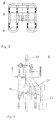
- the foot 10 of the trough chain conveyor 5 is provided with a level probe 12.
- This level probe 12 can, for. B. be a float or a capacitive sensor.
- the level probe 12 enables one sink in "Automatic, which enables the boom 2 to be lowered depending on the degree of filling of the ship. The boom 2 can follow the movements of the ship, so that not only is a high conveying capacity guaranteed, but also a load on the jack steel structure is avoided.
- the foot 10 also has a shaft with a conical feed, the Contains inclined walls 11. These walls 11 allow one better product intake and filling level as well as a reduction in wear of conveyor chain 7 and shaft.
Abstract
Description
Die Erfindung betrifft einen Schiffsentlader mit einem Trogkettenförderer, insbesondere einen Portalkran zur steilen Entladung von Schiffen und sonstigen Behältnissen gemäss dem Oberbegriff des Patentanspruchs 1.The invention relates to a ship unloader with a trough chain conveyor, in particular a gantry crane for the steep unloading of ships and other containers according to the preamble of claim 1.
Portalkrane mit Trogkettenförderern bzw. auch Trogkettenförderer als solche sind bekannt. So zeigt die EP-A-025981 einen Trogkettenförderer mit einem Fördertrog und einem Rücklauftrog, die sich zwischen einem Fuss und einem Entladekopf erstrecken. Eine umlaufende Förderkette ist mit von unten offenen Mitnehmern versehen. Das abzugebende Fördergut gelangt durch Schwerkraftentleerung über abwärts gerichtete Rutschen und teilweise durch Fliehkraftentleerung zu einem Kanal, dessen Eintrittsöffnung sich in Richtung parallel zur Umlaufebene über den Rücklauftrog hinaus erstreckt. Bei Ausbildung der Mitnehmer als Bügel erstreckt sich die Eintrittsöffnung seitlich an die Umlaufebene angrenzend an den Rücklauftrog und den Fördertrog. Auf der vom Fördertrog abgewandten Seite des Rücklauftroges ist eine, das abgeschleuderte Material aus der Umlaufebene seitlich in den sich über den Rücklauftrog hinaus erstreckenden Teil der Eintrittsöffnung lenkende weitere Rutsche vorgesehen.Gantry cranes with trough chain conveyors or trough chain conveyors as such are known. For example, EP-A-025981 shows a trough chain conveyor with a conveyor trough and a return trough extending between a foot and an unloading head. A rotating conveyor chain is provided with drivers that are open from below. The material to be delivered passes downwards through gravity emptying directed slides and partly by centrifugal emptying to a channel, the Inlet opening in the direction parallel to the circulation level via the return trough extends beyond. When the carriers are designed as a bracket, the inlet opening extends to the side of the circulation level adjacent to the return trough and the Conveyor trough. On the side of the return trough facing away from the conveyor trough there is a the thrown material from the circulation level laterally in the over the Another slide guiding the return trough extending part of the inlet opening intended.
Aus der DE-A-4429536 ist ein stetigfördernder Schiffsentlader bekannt, der einen Senkrechtförderer mit einem, auf einer Drehplattform heb- und senkbar angeordneten Ausleger mit einer auf einem Ponton angeordneten Portalbrücke mit Förderbändern und dergleichen zum entladen von Schüttgut aus Seeschiffen aufweist. Der Senkrechtförderer ist mit dem Ausleger heb- und senkbar und kann unabhängig hiervon auch längs und quer zur Richtung des Auslegers geschwenkt werden.From DE-A-4429536 a steadily conveying ship unloader is known, the one Vertical conveyor with one that can be raised and lowered on a rotating platform Boom with a portal bridge with conveyor belts arranged on a pontoon and the like for unloading bulk goods from seagoing vessels. The The vertical conveyor can be raised and lowered with the boom and can do this independently can also be swung lengthways and crossways to the direction of the boom.
Eine weitere Einrichtung zum Beladen von Schiffen mit Schüttgut zeigt die DE-A-19505372. Diese weist ebenfalls einen Ausleger auf, der auf einem parallel zu dem zu beladenden Schiff verfahrbaren Portal heb- und senkbar angeordnet ist, wobei der Ausleger ein Förderband trägt. Another device for loading ships with bulk material is shown in DE-A-19505372. This also has a boom that runs on a parallel to the to be loaded ship movable portal is arranged raised and lowered, the Boom carries a conveyor belt.
Der Erfindung liegt die Aufgabe zugrunde, einen gattungsgemässen Schiffsentlader, insbesondere einen Portalkran mit einem Trogkettenförderer so weiter zu entwickeln, dass dessen Gebrauchseigenschaften verbessert werden. Die Aufgabe ist an Hand der kennzeichnenden Merkmale des Patentanspruchs gelöst.The invention has for its object a generic ship unloader, especially to further develop a gantry crane with a trough chain conveyor, that its usage properties are improved. The task is on hand of the characterizing features of the claim.
Auf Grund der Ausgestaltung des Schachtes des Trogkettenförderers mit konischem Einzug wird der Füllgrad erhöht und der Verschleiss sinkt.Due to the design of the shaft of the trough chain conveyor with conical The fill level is increased and the wear decreases.
Vorteilhafte weiterführende Ausbildungen sind in den Unteransprüchen aufgeführt.
Die bevorzugte Anbringung einer Füllstandssonde am Fuss des Trogkettenförderers
ermöglicht eine ![]()
![]()
Ebenso ist der Schacht bevorzugt sphärisch gelagert, um eine Übertragung von Torsionskräften vom Schiff auf den Schiffsentlader zu vermeiden.Likewise, the shaft is preferably spherical in order to transmit torsional forces to avoid from ship to ship unloader.
Die Erfindung ist nachfolgend in einem Ausführungsbeispiel an Hand einer Zeichnung näher beschrieben. In der Zeichnung zeigen die
- Fig. 1:
- eine Seitenansicht des Schiffsentladers
- Fig. 2:
- den Fuss des Trogkettenförderers
- Fig. 3:
- einen Mitnehmer der Förderkette
- Fig. 4:
- eine Drehgosse.
- Fig. 1:
- a side view of the ship unloader
- Fig. 2:
- the foot of the trough chain conveyor
- Fig. 3:
- a driver of the conveyor chain
- Fig. 4:
- a rotary gutter.
Ein Schiffsentlader 1 weist einen Ausleger 2 auf, der auf einem, parallel zu einem
nicht dargestellten Schiff verfahrbaren Portal 3 heb- und senkbar sowie schwenkbar
angeordnet ist. Der Ausleger 2 trägt übliche Fördereinrichtungen, vorzugsweise ein
Kettenförderer zum Transport des entnommenen Schüttgutes in, am Kai 4 befindliche
Lagerbehältnise.A ship unloader 1 has a
Am, dem Schiff zugewandten Ende des Auslegers 2 ist ein Trogkettenförderer 5 angeordnet,
welcher ein Kicksystem mit einem, auf der Oberseite des Auslegers 2 angeordneten
Hydraulikzylinder 6 aufweist (Kick-in, Kick-out). Der Trogkettenförderer 5
kann damit gegenüber der Längsachse des Auslegers 2 um mehr als 90° geschwenkt
werden, in Abhängigkeit von der Arbeitsstellung des Auslegers 2. In der
Fig. 1 ist die Nullstellung gezeigt.A
Der Trogkettenförderer 5 weist ein sphärisches Lager 16 auf, um eine Übertragung
von Torsionskräften, die vom Schiff herrühren zu vermeiden. Ein seitlicher Neigungsausgleich
von ca. +/- 10° ist möglich.The
Im Trogkettenförderer 5, der im wesentlichen entsprechend der Offenbarung der EP-A-025981
aufgebaut ist, läuft eine Förderkette 7 mit Mitnehmern 8 um. In wählbarem
Abstand sind Mitnehmer 8 mit Füllblechen 9 versehen, um die Restentleerung des
Trogkettenförderers zu verbessern. Durch Antrieb eines Kettenrades läuft die Förderkette
7 um. Unten vom Fuss 10 aufgenommenes Schüttgut wird nun innerhalb
des Fördertroges des Trogkettenförderers 5 als kontinuierliche Säule nach oben gefördert
und gelangt gemäss EP-A-025981 in einen Förderkanal 20. Von diesem gelangt
es über eine Drehgosse 21 und einen weiteren Kanal 22 staubfrei und stellungsunabhängig
auf das Förderelement des Auslegers. Die Querstege 8, 9 können
aus einem Kunststoff gefertigt sein, woraus eine höhere Lebensdauer sowie eine
geringere Lärmentwicklung resultieren.In the
Durch wenden der Förderkette 7 können beide Schachtseiten genutzt werden.By turning the
Der Fuss 10 des Trogkettenförderers 5 ist mit einer Füllstandssonde 12 versehen.
Diese Füllstandssonde 12 kann z. B. ein Schwimmer oder auch ein kapazitiver Sensor
sein. Die Füllstandssonde 12 ermöglicht eine
Der Fuss 10 weist weiterhin einen Schacht mit konischem Einzug auf, wobei der
Schacht schräg gestellte Wände 11 enthält. Diese Wände 11 ermöglichen einen
besseren Produkteinzug und Füllgrad sowie eine Verringerung des Verschleisses
von Förderkette 7 und Schacht. The
- 11
- SchiffsentladerShip unloaders
- 22nd
- Auslegerboom
- 33rd
- Portalportal
- 44th
- KaiKai
- 55
- TrogkettenfördererTrough chain conveyor
- 66
- HydraulikzylinderHydraulic cylinder
- 77
- FörderketteConveyor chain
- 88th
- MitnehmerDriver
- 99
- FüllblechFiller plate
- 1010th
- FussFoot
- 1111
- Wandwall
- 1212th
- FüllstandssondeLevel probe
- 1616
- Lagercamp
- 2020th
- FörderkanalConveyor channel
- 2121
- DrehgosseRotary drain
- 2222
- Kanalchannel
Claims (8)
Applications Claiming Priority (2)
| Application Number | Priority Date | Filing Date | Title |
|---|---|---|---|
| DE19937653 | 1999-08-12 | ||
| DE19937653A DE19937653A1 (en) | 1999-08-12 | 1999-08-12 | Ship unloader with trough chain conveyor |
Publications (2)
| Publication Number | Publication Date |
|---|---|
| EP1076024A1 true EP1076024A1 (en) | 2001-02-14 |
| EP1076024B1 EP1076024B1 (en) | 2006-03-29 |
Family
ID=7917796
Family Applications (1)
| Application Number | Title | Priority Date | Filing Date |
|---|---|---|---|
| EP00114343A Expired - Lifetime EP1076024B1 (en) | 1999-08-12 | 2000-07-04 | Unloading device for ships with troughed chain conveyor |
Country Status (5)
| Country | Link |
|---|---|
| EP (1) | EP1076024B1 (en) |
| AT (1) | ATE321716T1 (en) |
| DE (2) | DE19937653A1 (en) |
| ES (1) | ES2259959T3 (en) |
| PT (1) | PT1076024E (en) |
Families Citing this family (2)
| Publication number | Priority date | Publication date | Assignee | Title |
|---|---|---|---|---|
| DE102012105449A1 (en) | 2012-06-22 | 2013-12-24 | Thyssenkrupp Resource Technologies Gmbh | Device for conveying bulk goods from container, particularly from ship loading space, has radar unit that is formed for detection of objects existing in container or in bulk goods by radar signal |
| CN106364922B (en) * | 2015-07-22 | 2018-06-19 | 南京梅山冶金发展有限公司 | The short route processing method and equipment of a kind of blending ore end material |
Citations (8)
| Publication number | Priority date | Publication date | Assignee | Title |
|---|---|---|---|---|
| EP0025981A1 (en) | 1979-09-21 | 1981-04-01 | Bühler AG | Flight conveyer for the steep unloading of ships and other containers |
| EP0039487A1 (en) * | 1980-05-07 | 1981-11-11 | Bühler AG | Elevator conveyor for unloading ships or other containers |
| US4467910A (en) * | 1980-11-28 | 1984-08-28 | Ab Scaniainventor | Vertical conveyor for bulk goods |
| DE4204251A1 (en) * | 1992-02-13 | 1993-08-19 | Gutehoffnungshuette Man | RECEIVING PROCEDURE FOR A CONTINUOUSLY PROMOTING SHIP UNLOADER |
| DE4429536A1 (en) | 1994-08-19 | 1996-02-22 | Man Takraf Foerdertechnik Gmbh | Ship unloader with continuous=flow conveyor |
| JPH08157074A (en) * | 1994-12-07 | 1996-06-18 | Mitsubishi Heavy Ind Ltd | Operation control method and operation control device for bucket elevator excavating device |
| DE19505372A1 (en) | 1995-02-17 | 1996-08-22 | Pwh Anlagen & Systeme Gmbh | Bulk loading mechanism for ship using jib on portal |
| US5807054A (en) * | 1996-06-14 | 1998-09-15 | Seymour; Timothy Harrison | Bulk unloader/reclaimer with bucket chair cover and guide |
Family Cites Families (1)
| Publication number | Priority date | Publication date | Assignee | Title |
|---|---|---|---|---|
| DE19508951C2 (en) * | 1995-03-13 | 1999-04-01 | Krupp Foerdertechnik Gmbh | Device for the constant unloading of bulk goods from ships |
-
1999
- 1999-08-12 DE DE19937653A patent/DE19937653A1/en not_active Withdrawn
-
2000
- 2000-07-04 AT AT00114343T patent/ATE321716T1/en not_active IP Right Cessation
- 2000-07-04 ES ES00114343T patent/ES2259959T3/en not_active Expired - Lifetime
- 2000-07-04 EP EP00114343A patent/EP1076024B1/en not_active Expired - Lifetime
- 2000-07-04 PT PT00114343T patent/PT1076024E/en unknown
- 2000-07-04 DE DE50012464T patent/DE50012464D1/en not_active Expired - Lifetime
Patent Citations (8)
| Publication number | Priority date | Publication date | Assignee | Title |
|---|---|---|---|---|
| EP0025981A1 (en) | 1979-09-21 | 1981-04-01 | Bühler AG | Flight conveyer for the steep unloading of ships and other containers |
| EP0039487A1 (en) * | 1980-05-07 | 1981-11-11 | Bühler AG | Elevator conveyor for unloading ships or other containers |
| US4467910A (en) * | 1980-11-28 | 1984-08-28 | Ab Scaniainventor | Vertical conveyor for bulk goods |
| DE4204251A1 (en) * | 1992-02-13 | 1993-08-19 | Gutehoffnungshuette Man | RECEIVING PROCEDURE FOR A CONTINUOUSLY PROMOTING SHIP UNLOADER |
| DE4429536A1 (en) | 1994-08-19 | 1996-02-22 | Man Takraf Foerdertechnik Gmbh | Ship unloader with continuous=flow conveyor |
| JPH08157074A (en) * | 1994-12-07 | 1996-06-18 | Mitsubishi Heavy Ind Ltd | Operation control method and operation control device for bucket elevator excavating device |
| DE19505372A1 (en) | 1995-02-17 | 1996-08-22 | Pwh Anlagen & Systeme Gmbh | Bulk loading mechanism for ship using jib on portal |
| US5807054A (en) * | 1996-06-14 | 1998-09-15 | Seymour; Timothy Harrison | Bulk unloader/reclaimer with bucket chair cover and guide |
Non-Patent Citations (1)
| Title |
|---|
| PATENT ABSTRACTS OF JAPAN vol. 1996, no. 10 31 October 1996 (1996-10-31) * |
Also Published As
| Publication number | Publication date |
|---|---|
| DE19937653A1 (en) | 2001-02-15 |
| EP1076024B1 (en) | 2006-03-29 |
| PT1076024E (en) | 2006-06-30 |
| DE50012464D1 (en) | 2006-05-18 |
| ATE321716T1 (en) | 2006-04-15 |
| ES2259959T3 (en) | 2006-11-01 |
Similar Documents
| Publication | Publication Date | Title |
|---|---|---|
| DE60310614T2 (en) | DEVICE FOR STORING AND UNLOADING GRANULES | |
| DE4429536C2 (en) | Continuous ship unloader | |
| DE1920874B2 (en) | FLOATING TRANSFER DEVICE | |
| DE3390175C2 (en) | ||
| EP1076024B1 (en) | Unloading device for ships with troughed chain conveyor | |
| DE10033141B4 (en) | System for reloading containers | |
| DE3840826C2 (en) | ||
| DE3427170C2 (en) | ||
| EP0741092A2 (en) | Unloading device for ships or similar containers for bulk material | |
| DE3447218A1 (en) | PIPE MAKER | |
| DE60319603T2 (en) | Device for storing and unloading granules | |
| DE3504587C2 (en) | ||
| NL8420145A (en) | TRANSPORT SYSTEM. | |
| DE10115072C2 (en) | Gutauforgan for a continuous ship unloader | |
| DE10115071C2 (en) | Gutauforgan for a continuous ship unloader | |
| CH618650A5 (en) | Carrier vehicle for containers | |
| DE102021130201A1 (en) | Skip for shaft hoisting systems | |
| DE3615521A1 (en) | DEVICE FOR LOADING AND / OR UNLOADING GENERALLY CLOSED PRODUCTS | |
| DE2308421A1 (en) | DEVICE FOR HANDLING BAGS | |
| DE1915095A1 (en) | Continuously working bulk goods unloader for ships | |
| DE2617110A1 (en) | PROCEDURE FOR UNLOADING BULK GOODS FROM CARRIERS | |
| DE10016980A1 (en) | System for unloading particularly difficult-to-flow bulk goods | |
| CA1144102A (en) | Hydraulic drill fill | |
| DE7612226U1 (en) | DEVICE FOR UNLOADING BULK CARGO FROM FREIGHTERS | |
| DE4405944A1 (en) | Pick=up device for ships unloader for free flowing solid material |
Legal Events
| Date | Code | Title | Description |
|---|---|---|---|
| PUAI | Public reference made under article 153(3) epc to a published international application that has entered the european phase |
Free format text: ORIGINAL CODE: 0009012 |
|
| 17P | Request for examination filed |
Effective date: 20000704 |
|
| AK | Designated contracting states |
Kind code of ref document: A1 Designated state(s): AT BE CH CY DE DK ES FI FR GB GR IE IT LI LU MC NL PT SE |
|
| AX | Request for extension of the european patent |
Free format text: AL;LT;LV;MK;RO;SI |
|
| AKX | Designation fees paid |
Free format text: AT BE CH CY DE DK ES FI FR GB GR IE IT LI LU MC NL PT SE |
|
| 17Q | First examination report despatched |
Effective date: 20041122 |
|
| GRAP | Despatch of communication of intention to grant a patent |
Free format text: ORIGINAL CODE: EPIDOSNIGR1 |
|
| GRAS | Grant fee paid |
Free format text: ORIGINAL CODE: EPIDOSNIGR3 |
|
| GRAA | (expected) grant |
Free format text: ORIGINAL CODE: 0009210 |
|
| AK | Designated contracting states |
Kind code of ref document: B1 Designated state(s): AT BE CH CY DE DK ES FI FR GB GR IE IT LI LU MC NL PT SE |
|
| PG25 | Lapsed in a contracting state [announced via postgrant information from national office to epo] |
Ref country code: IE Free format text: LAPSE BECAUSE OF FAILURE TO SUBMIT A TRANSLATION OF THE DESCRIPTION OR TO PAY THE FEE WITHIN THE PRESCRIBED TIME-LIMIT Effective date: 20060329 |
|
| REG | Reference to a national code |
Ref country code: GB Ref legal event code: FG4D Free format text: NOT ENGLISH |
|
| REG | Reference to a national code |
Ref country code: CH Ref legal event code: EP |
|
| GBT | Gb: translation of ep patent filed (gb section 77(6)(a)/1977) |
Effective date: 20060329 |
|
| REG | Reference to a national code |
Ref country code: IE Ref legal event code: FG4D Free format text: LANGUAGE OF EP DOCUMENT: GERMAN |
|
| REF | Corresponds to: |
Ref document number: 50012464 Country of ref document: DE Date of ref document: 20060518 Kind code of ref document: P |
|
| PG25 | Lapsed in a contracting state [announced via postgrant information from national office to epo] |
Ref country code: SE Free format text: LAPSE BECAUSE OF FAILURE TO SUBMIT A TRANSLATION OF THE DESCRIPTION OR TO PAY THE FEE WITHIN THE PRESCRIBED TIME-LIMIT Effective date: 20060629 Ref country code: DK Free format text: LAPSE BECAUSE OF FAILURE TO SUBMIT A TRANSLATION OF THE DESCRIPTION OR TO PAY THE FEE WITHIN THE PRESCRIBED TIME-LIMIT Effective date: 20060629 |
|
| REG | Reference to a national code |
Ref country code: PT Ref legal event code: SC4A Effective date: 20060412 |
|
| PG25 | Lapsed in a contracting state [announced via postgrant information from national office to epo] |
Ref country code: MC Free format text: LAPSE BECAUSE OF NON-PAYMENT OF DUE FEES Effective date: 20060731 |
|
| ET | Fr: translation filed | ||
| REG | Reference to a national code |
Ref country code: ES Ref legal event code: FG2A Ref document number: 2259959 Country of ref document: ES Kind code of ref document: T3 |
|
| REG | Reference to a national code |
Ref country code: IE Ref legal event code: FD4D |
|
| PLBE | No opposition filed within time limit |
Free format text: ORIGINAL CODE: 0009261 |
|
| STAA | Information on the status of an ep patent application or granted ep patent |
Free format text: STATUS: NO OPPOSITION FILED WITHIN TIME LIMIT |
|
| 26N | No opposition filed |
Effective date: 20070102 |
|
| PG25 | Lapsed in a contracting state [announced via postgrant information from national office to epo] |
Ref country code: AT Free format text: LAPSE BECAUSE OF NON-PAYMENT OF DUE FEES Effective date: 20060704 |
|
| PG25 | Lapsed in a contracting state [announced via postgrant information from national office to epo] |
Ref country code: GR Free format text: LAPSE BECAUSE OF FAILURE TO SUBMIT A TRANSLATION OF THE DESCRIPTION OR TO PAY THE FEE WITHIN THE PRESCRIBED TIME-LIMIT Effective date: 20060630 |
|
| PG25 | Lapsed in a contracting state [announced via postgrant information from national office to epo] |
Ref country code: LU Free format text: LAPSE BECAUSE OF NON-PAYMENT OF DUE FEES Effective date: 20060704 |
|
| PG25 | Lapsed in a contracting state [announced via postgrant information from national office to epo] |
Ref country code: CY Free format text: LAPSE BECAUSE OF FAILURE TO SUBMIT A TRANSLATION OF THE DESCRIPTION OR TO PAY THE FEE WITHIN THE PRESCRIBED TIME-LIMIT Effective date: 20060329 |
|
| PGFP | Annual fee paid to national office [announced via postgrant information from national office to epo] |
Ref country code: PT Payment date: 20090619 Year of fee payment: 10 Ref country code: FI Payment date: 20090624 Year of fee payment: 10 |
|
| REG | Reference to a national code |
Ref country code: PT Ref legal event code: MM4A Free format text: LAPSE DUE TO NON-PAYMENT OF FEES Effective date: 20110104 |
|
| PG25 | Lapsed in a contracting state [announced via postgrant information from national office to epo] |
Ref country code: PT Free format text: LAPSE BECAUSE OF NON-PAYMENT OF DUE FEES Effective date: 20110104 Ref country code: FI Free format text: LAPSE BECAUSE OF NON-PAYMENT OF DUE FEES Effective date: 20100704 |
|
| PGFP | Annual fee paid to national office [announced via postgrant information from national office to epo] |
Ref country code: ES Payment date: 20130722 Year of fee payment: 14 Ref country code: CH Payment date: 20130723 Year of fee payment: 14 Ref country code: NL Payment date: 20130722 Year of fee payment: 14 |
|
| PGFP | Annual fee paid to national office [announced via postgrant information from national office to epo] |
Ref country code: GB Payment date: 20130723 Year of fee payment: 14 Ref country code: FR Payment date: 20130719 Year of fee payment: 14 |
|
| REG | Reference to a national code |
Ref country code: DE Ref legal event code: R082 Ref document number: 50012464 Country of ref document: DE Representative=s name: VOSSIUS & PARTNER PATENTANWAELTE RECHTSANWAELT, DE |
|
| REG | Reference to a national code |
Ref country code: NL Ref legal event code: V1 Effective date: 20150201 |
|
| REG | Reference to a national code |
Ref country code: CH Ref legal event code: PL |
|
| GBPC | Gb: european patent ceased through non-payment of renewal fee |
Effective date: 20140704 |
|
| PG25 | Lapsed in a contracting state [announced via postgrant information from national office to epo] |
Ref country code: NL Free format text: LAPSE BECAUSE OF NON-PAYMENT OF DUE FEES Effective date: 20150201 |
|
| REG | Reference to a national code |
Ref country code: FR Ref legal event code: ST Effective date: 20150331 |
|
| PG25 | Lapsed in a contracting state [announced via postgrant information from national office to epo] |
Ref country code: LI Free format text: LAPSE BECAUSE OF NON-PAYMENT OF DUE FEES Effective date: 20140731 Ref country code: CH Free format text: LAPSE BECAUSE OF NON-PAYMENT OF DUE FEES Effective date: 20140731 |
|
| PG25 | Lapsed in a contracting state [announced via postgrant information from national office to epo] |
Ref country code: GB Free format text: LAPSE BECAUSE OF NON-PAYMENT OF DUE FEES Effective date: 20140704 Ref country code: FR Free format text: LAPSE BECAUSE OF NON-PAYMENT OF DUE FEES Effective date: 20140731 |
|
| REG | Reference to a national code |
Ref country code: ES Ref legal event code: FD2A Effective date: 20150826 |
|
| PG25 | Lapsed in a contracting state [announced via postgrant information from national office to epo] |
Ref country code: ES Free format text: LAPSE BECAUSE OF NON-PAYMENT OF DUE FEES Effective date: 20140705 |
|
| PGFP | Annual fee paid to national office [announced via postgrant information from national office to epo] |
Ref country code: IT Payment date: 20190723 Year of fee payment: 20 Ref country code: DE Payment date: 20190723 Year of fee payment: 20 |
|
| PGFP | Annual fee paid to national office [announced via postgrant information from national office to epo] |
Ref country code: BE Payment date: 20190722 Year of fee payment: 20 |
|
| REG | Reference to a national code |
Ref country code: DE Ref legal event code: R071 Ref document number: 50012464 Country of ref document: DE |
|
| REG | Reference to a national code |
Ref country code: BE Ref legal event code: MK Effective date: 20200704 |