EP1077161A2 - Multi-functional on-vehicle camera system and image display method for the same - Google Patents
Multi-functional on-vehicle camera system and image display method for the same Download PDFInfo
- Publication number
- EP1077161A2 EP1077161A2 EP00117542A EP00117542A EP1077161A2 EP 1077161 A2 EP1077161 A2 EP 1077161A2 EP 00117542 A EP00117542 A EP 00117542A EP 00117542 A EP00117542 A EP 00117542A EP 1077161 A2 EP1077161 A2 EP 1077161A2
- Authority
- EP
- European Patent Office
- Prior art keywords
- image
- vehicle
- camera
- cameras
- functional
- Prior art date
- Legal status (The legal status is an assumption and is not a legal conclusion. Google has not performed a legal analysis and makes no representation as to the accuracy of the status listed.)
- Granted
Links
Images


Classifications
-
- B—PERFORMING OPERATIONS; TRANSPORTING
- B60—VEHICLES IN GENERAL
- B60R—VEHICLES, VEHICLE FITTINGS, OR VEHICLE PARTS, NOT OTHERWISE PROVIDED FOR
- B60R11/00—Arrangements for holding or mounting articles, not otherwise provided for
- B60R11/04—Mounting of cameras operative during drive; Arrangement of controls thereof relative to the vehicle
Definitions
- the present invention relates to a multi-functional on-vehicle camera system which comprises a plurality of monitoring cameras mounted on a vehicle and a display unit for displaying a monitored image. Furthermore, the present invention relates to an image display method for this multi-functional on-vehicle camera system. More specifically, the present invention provides a monitor image display letting a driver easily know circumferential conditions surrounding the vehicle. Moreover, the present invention displays such images at an appropriate timing according to driving conditions.
- a small camera is mounted on a vehicle and directed to a specific direction to take an image not directly viewed by a driver's eye.
- the taken image is displayed on a monitor in a passenger compartment of the vehicle.
- a vehicle monitoring system comprising a plurality of cameras 1, 2, 3 and 4 mounted on a vehicle, a turning direction detecting section 5 for detecting a turning direction of the vehicle based on a winker signal, a steering direction detecting section 6 for detecting a steering direction of a steering wheel, an instruction input section 7 for allowing a driver to enter driver's instructions, a switching control section 8 for selecting an appropriate one of images taken by the plurality of cameras 1, 2, 3 and 4 based on information obtained from the associated sections 5, 6 and 7, and an image display section (i.e., monitor) 9 for displaying the image selected by the switching control section 8.
- a turning direction detecting section 5 for detecting a turning direction of the vehicle based on a winker signal
- a steering direction detecting section 6 for detecting a steering direction of a steering wheel
- an instruction input section 7 for allowing a driver to enter driver's instructions
- a switching control section 8 for selecting an appropriate one of images taken by the plurality of cameras 1, 2, 3 and 4 based on information
- the images taken by cameras mounted on a front side of a vehicle may be selectively displayed in accordance with a turning of the vehicle to the right or to the left.
- it is important for the driver to promptly understand the displayed image without taking a time to judge whether this image is a right side view seen from the vehicle or a left side view seen from the vehicle.
- Such a prompt judgement is essentially important for a skillful driving operation.
- a word indicating the direction e.g., "right” or "left”
- a relatively long time is required for these steps. It may be unable to avoid an accident due to delay in grasping information obtained from the displayed image.
- the driver may not be able to quickly discriminate "right” from “left” or vice versa.
- the driver may rely on an image taken by a camera mounted on a rear side of the vehicle.
- the intended vacant space may not be clearly displayed on the monitor due to presence of another vehicles already in this parking lot. In such a case, the driver cannot rely on the displayed image and will hesitate in steering the vehicle to a target place while avoiding obstacles.
- the present invention has an object to provide a multi-functional on-vehicle camera system capable of displaying an image for assisting the safety driving at an appropriate timing according to driving conditions in such a manner that the driver can easily grasp the displayed image.
- the present invention has an object to provide an image display method for such a multi-functional on-vehicle camera system.
- the present invention provides a multi-functional on-vehicle camera system comprising a plurality of cameras mounted on a vehicle and a display unit displaying at least one camera image, wherein image processing means is provided for processing images taken by the plurality of cameras, and system control means is provided for selecting at least one camera image to be processed in the image processing means from the images taken by the plurality of cameras based on vehicle conditions, and for controlling a type of image processing performed in the image processing means.
- the multi-functional on-vehicle camera system further comprises graphic superimposing means for superimposing a graphic pattern on the image processed by the image processing means.
- the system control means controls both a type and a position of the graphic pattern superimposed by the graphic superimposing means.
- the plurality of cameras include at least two cameras selected from the group consisting of a rear camera taking a rear view seen from the vehicle, right and left pillar cameras taking right and left rear side views seen from the vehicle, right and left door mirror cameras taking right and left door mirror views seen from the vehicle via right and left door mirrors, right and left lateral cameras taking front side views seen from the vehicle, and a front camera taking a front view seen from the vehicle.
- the display unit includes a right monitor displaying an image taken by a right door mirror camera, and a left monitor displaying an image taken by a left door mirror camera.
- the image processing means produces a plan view image based on images of a plurality of cameras so that the plan view image includes an image of the vehicle seen from above.
- the image processing means produces a panorama image based on images of a plurality of cameras.
- the image processing means produces a joint image by combining images of a plurality of cameras.
- the image processing means produces a surrounding image representing a surrounding view seen from the vehicle by successively connecting images of all of the plurality of cameras mounted on the vehicle.
- the image processing means produces an image formed by using part of image data obtained from the plurality of cameras.
- the image processing means produces an image including a moving object approaching or leaving with respect to the vehicle so that the moving object is emphasizing by a different color.
- the system control means designates the camera image to be used in the image processing and designates the type of image processing performed in the image processing means based on at least one signal representing vehicle conditions selected from the group consisting of a steering angle signal, a vehicle speed signal, gear position information and winker information.
- the graphic superimposing means superimposes a graphic pattern of a moving object approaching or leaving with respect to the vehicle.
- the present invention provides an image display method for a multi-functional on-vehicle camera system comprising a plurality of cameras mounted on a vehicle and a display unit displaying at least one camera image, the image display method comprising a step of processing at least one camera image selected from the a plurality of images obtained from the plurality of cameras based on vehicle conditions, and a step of displaying a processed camera image on the display unit.
- the plurality of cameras include at least two cameras selected from the group consisting of the rear camera, the right and left pillar cameras, the right and left door mirror cameras, the right and left lateral cameras, and the front camera. And, the images of at least two cameras are processed in the image processing means and displayed on the display unit.
- a plan view image is produced and displayed based on at least three images of the rear camera and the right and left pillar cameras when the vehicle moves backward for parking.
- a plan view image is produced and displayed based on at least three images of the rear camera, the left pillar camera and the left door mirror camera when the vehicle moves backward for parking along a left side of a road.
- a plan view image is produced and displayed based on at least three images of the rear camera, the right pillar camera and the right door mirror camera when the vehicle moves backward for parking along a right side of a road.
- a panorama image is produced and displayed by combining at least two images of the left door camera and the left pillar camera when the vehicle turns left, thereby eliminating an accident occurring at an inside of the vehicle during a left turning or cornering operation.
- a panorama image is produced and displayed by combining at least two images of the right door camera and the right pillar camera when the vehicle turns right, thereby eliminating an accident occurring at an inside of the vehicle during a right turning or cornering operation.
- a panorama image is produced and displayed by combining at least two images of the left pillar camera and the rear camera when the vehicle performs lane changing to a left lane.
- a panorama image is produced and displayed by combining at least two images of the right pillar camera and the rear camera when the vehicle performs lane changing to a right lane.
- the display unit includes a right monitor displaying an image taken by the right door mirror camera and a left monitor displaying an image taken by the left door mirror camera.
- each of the right and left monitors displays a limited image seen within a view angle of a corresponding door mirror when the vehicle is traveling.
- a panorama image is produced and displayed by combining three images of the right and left pillar cameras and the rear camera when the vehicle is traveling ordinarily.
- a joint image is produced and displayed by combining two images of the right and left lateral cameras when the vehicle is traveling slowly or stopped for confirmation of forward or side obstacles.
- the image of the right lateral camera is enlarged when the vehicle turns right, and the image of the left lateral camera is enlarged when the vehicle turns left.
- the image displayed on the display unit includes a moving object approaching or leaving with respect to the vehicle, and the object is emphasizing by a different color.
- a graphic pattern is superimposed on the displayed image so that the graphic pattern represents a moving object approaching or leaving with respect to the vehicle.
- the image taken by the door mirror camera is continuously displayed when any passenger is in the vehicle.
- the multi-functional on-vehicle camera system in accordance with a preferred embodiment of the present invention comprises a total of eight cameras mounted circumferentially on a vehicle.
- Fig. 4 shows a total of three monitors installed in a passenger compartment of the vehicle.
- a main monitor 19 is embedded in a dash board.
- a left view monitor 20 and a right view monitor 21 are installed near the upper end of a front windshield glass.
- the main monitor 19 has a screen size larger than those of the left and right view monitors 20 and 21.
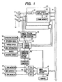
- Fig. 1 is a block diagram showing a schematic arrangement of a vehicle incorporating the multi-functional on-vehicle camera system of the present invention.
- Each of the above-described cameras 11 to 18 mounted on the vehicle is constituted by a solid image pickup element, such as CCD or CMOS image pickup element.
- An image data transmitting section 31, associated with a corresponding camera converts a video signal of this camera into image data and transmits the converted image data via a vide bus 35.
- An image processing section 47 receives the image data transmitted via the video bus 35 to analyze the image data and perform editing and composing processing.
- a memory 48 is used as a work area for the image processing.
- a plurality of D/A converting sections 50-52 convert the processed image data into an analog signal.
- a character generator 46 produces a graphic pattern displayed in accordance with a code.
- a character generator control section 45 controls the graphic pattern produced from the character generator 46.
- a mixer 49 mixes the graphic pattern produced from the character generator 46 with the image produced from the D/A converter 50.
- the main monitor 19, the left view monitor 20, and the right view monitor 21 display the image.
- a camera control section 43 controls the direction/angle of each of the cameras 11-18 as well as image pickup conditions.
- An alarm generating section 44 raises the alarm.
- a system control section 42 controls various sections based on driver's instructions entered from an operating section 36, a steering angle signal 37, a vehicle speed signal 38, gear position information 39, a winker signal 40 and a supersonic distance sensor 41.
- each image data transmitting section 31 comprises an A/D converting section 32 converting the video signal of each camera into a digital signal, a frame memory 34 storing image data, and a frame memory control section 33 controlling storage and transmission of the image data.
- the cameras 11-18 produce various video signals in conformity with NTSC standards, PAL standards etc. Or, the camera output signals may meet the VGA standards.
- the video signals for each standard include R,G and B outputs, Y, U and V outputs, a composite output, as well as digital outputs.
- the digital outputs require no A/D and D/A converters.
- the system control section 42 inputs various sensing signals; e.g., the steering angle signal 37 representing a steering angle of a steering wheel, the vehicle speed signal 38 representing a rotational speed of a wheel, the gear position information 39 representing a gear position in a power train mechanism of the vehicle, the winker signal 40 responsive to a right or left turning lever, and the supersonic distance sensor 41 located at a front or rear side of the vehicle to detect a distance from this vehicle to a neighboring vehicle or obstacle.
- various sensing signals e.g., the steering angle signal 37 representing a steering angle of a steering wheel, the vehicle speed signal 38 representing a rotational speed of a wheel, the gear position information 39 representing a gear position in a power train mechanism of the vehicle, the winker signal 40 responsive to a right or left turning lever, and the supersonic distance sensor 41 located at a front or rear side of the vehicle to detect a distance from this vehicle to a neighboring vehicle or obstacle.
- the system control section 42 controls each image data transmitting section 31 based on the obtained information as well as the driver's instructions entered from the operating section 36.
- the system control section 42 sends selected image data obtained from the cameras 11-18 to the image processing section 47. Furthermore, the system control section 42 controls the way of processing images in the image processing section 47. To this end, the system control section 42 controls the camera control section 43 to adjust the direction/angle of each camera, thereby obtaining necessary image data.
- the image processing section 47 analyzes the received image data, edits the image data, and composes the images based on instructions sent from the system control section 42. Furthermore, the image processing section 47 sends required analysis result to the system control section 42. The system control section 42 activates the alarm generating section 44 and controls the character generator control section 45 if necessary based on the obtained analysis result.
- the character generator control section 45 when it receives an instruction from the system control section 42, causes the character generator 46 to output a graphic pattern to be superimposed on the image processed by the image processing section 47.
- the monitors 19 to 21 display the images at an appropriate timing according to driving conditions in such a manner that the driver can easily grasp the displayed image.
- the plan view image i.e., an image of the vehicle and surroundings seen from above, is obtained by analyzing and composing the plurality of images obtained from the cameras mounted on the vehicle. For example, when the vehicle moves backward for parking, the main monitor 19 displays the plan view image of a parking lot seen from above. Thus, the driver can clearly recognize a vacant space in the parking lot based on the image displayed on the main monitor 19.
- a non-published Japanese patent application No. 11-109946 discloses details about the method for creating the plan view image.
- Fig. 6 shows the procedure of forming the plan view image by using the images obtained from the door mirror cameras 14 and 15, the pillar cameras 16 and 17, and the rear camera 18 shown in Fig. 5.
- the left side and the central portion of a composite image is formed based on the images obtained from the left door mirror camera 14, the left pillar camera 16, and the rear camera 18.
- the images obtained from the left door mirror camera 14, the left pillar camera 16, and the rear camera 18 are converted into projective images projected on the road.
- a road area is determined so as to correspond to the field of view of each camera shown in Fig. 5.
- the image taken by each camera is converted into the projected-on-road image through coordinate conversion.
- Each projected-on-road image thus obtained is weighted in accordance with an ⁇ map which indicates an area necessary for forming the plan view image.
- the weighted images are then combined to form a composite image.
- the images of the right door mirror camera 15 and the right pillar camera 17 are processed in the same manner. Thus, all of the weighted images being weighted by ⁇ maps are combined to form a composite image.
- a graphic image representing an automotive vehicle is disposed on a vehicle position in the obtained composite image.
- the memory 48 stores the graphic image representing an automotive vehicle.
- plan view image includes the system vehicle and surroundings.
- plan view image emphasizes the rear side of the system vehicle based on the images of the door mirror cameras 14 and 15, the pillar cameras 16 and 17 and the rear camera 18. It is however possible to obtain a plan view image emphasizing the left side and the left rear side of the system vehicle based on the images of the left lateral camera 12, the left door mirror camera 14, the left pillar camera 16, and the rear camera 18. Similarly, it is possible to obtain a plan view image emphasizing the right side and the right rear side of the system vehicle from the images of the right lateral camera 13, the right door mirror camera 15, the right pillar camera 17, and the rear camera 18. These two plan image views serve as useful image information for assisting the driver when parking along left and right sides of a road.
- the number of cameras used for forming the plan view image may be two or less.
- the panorama image is a super wide image obtained by combining a plurality of images taken by the cameras mounted on the vehicle. More specifically, the panorama image has a view angle of approximately 160-170° whereas an ordinary wide image has a view angle of approximately 120°.
- Fig. 8 shows a method of forming the panorama image.
- an image 91 of the right door mirror camera 15 and an image 92 of the right pillar camera 17 are analyzed to detect image elements commonly involved in the analyzed images 91 and 92.
- a panorama image is composed by overlapping the common elements involved in both images 91 and 92.
- the panorama image is advantageous compared with the normal images having more narrower view angles in that the driver can immediately understand the relationship between the actual position and the displayed image.
- the panorama image makes it possible for the driver to perform the vehicle driving operation properly without any hesitation.
- the system control section 42 instructs the camera control section 43 to perform the direction/angle adjustment for respective cameras 11-18.
- the surrounding image is formed by successively connecting all the images taken by the cameras 11-18 based on a driver's instruction of the operating section 36.
- the surrounding image is an image continuously displaying surroundings or circumstances around the vehicle.
- the operating section 36 is a joystick type which allows the driver to instruct a preferable direction.
- the system control section 42 causes the image data transmitting sections 31 of appropriate neighboring cameras, e.g., camera 11 and camera 12, located in the driver's instructing direction to output images.
- the image processing section 47 connects the output images by overlapping the same image elements as performed in the formation of the panorama image.
- the main monitor 19 displays the surrounding image successively along an entire circumference of the vehicle.
- the camera control section 43 adjusts the direction/angle of respective cameras 11-18 based on the instruction sent from the system control section 42 so as to optimize the resultant surrounding image.
- the joint image is a combination of two discontinuous images with a clear boundary thereof.
- the driver may intend to turn the vehicle right in a slow speed condition.
- the main monitor 19 displays a joint image consisting of the image taken by the left lateral camera 12 and the image taken by the right lateral camera 13 as shown in Fig. 9A.
- the main monitor 19 enlarges the image taken by the left lateral camera 12 compared with the image taken by the right lateral camera 13.
- the main monitor 19 enlarges the image taken by the right lateral camera 13 compared with the image taken by the left lateral camera 12.
- the driver can perceive the camera direction of each displayed image intuitionally in connection with the advancing direction of the vehicle.
- the image corresponding to the turning direction of the vehicle is enlarged because the driver should pay a greater caution to the turning direction of the vehicle.
- the driver can unconsciously find the image to be paid attention.
- the view field limited image is a limited image taken by each of the door mirror camera 14 and 15, corresponding an image seen within a view angle of a door mirror when the vehicle is traveling, as shown in Fig. 7.
- the image processing section 47 abandons the image data outside a door mirror effective area from the image data of each of the door mirror cameras 14 and 15. Furthermore, the image processing section 47 enlarges the image data of the door mirror effective area to a full range of the screen.
- the limited image taken by the left door mirror camera 14 is displayed on the left view monitor 20.
- the limited image taken by the right door mirror camera 15 is displayed on the right view monitor 21.
- the reason why the images of the door mirror cameras 14 and 15 are converted into the view field limited images is to effectively utilize the drive feeling acquired through driver's experiences.
- the driver can look the displayed images of the left view monitor 20 and the right view monitor 21 without any unusual feeling.
- the information obtained from the door mirror cameras 14 and 15 is substantially identical with the information obtained from the door mirrors.
- the image information outside the door mirror effective area is not so useful in the vehicle traveling condition. It is thus believed that clearly displaying the image of the door mirror effective area can provide a meaningful display.
- a supplementary graphic pattern is added or part of the displayed image is modified.
- the following is practical examples of additional image information.
- a red frame is put on an automotive vehicle approaching to the system vehicle while a green frame is put on a vehicle or other object leaving from the system vehicle.
- the image processing section 47 detects a motion vector based on the frame-by-frame comparison on the image data taken by the front camera 11.
- the image processing section 47 obtains coordinate values of an object approaching to or leaving from the system vehicle.
- the image processing section 47 transmits the obtained coordinate values of the approaching or leaving object to the system control section 42.
- the system control section 42 instructs the character generator control section 45 to output a red or green frame and designates its position.
- the character generator control section 45 controls the character generator 46 to outputs a designated graphic pattern to a designated position.
- the graphic pattern produced from the character generator 46 is sent to the mixer 49.
- the mixer 49 mixes the received graphic pattern with the image processed by the image processing section 47.
- the main monitor 19 displays the resultant image including an approaching object encircled by the red frame and a leaving object encircled by the green frame.
- the approaching object itself can be emphasized by red and the leaving object can be emphasized by green.
- Fig. 10 is a functional block diagram showing the arrangement of the image processing section 47 to realize such display.
- the image processing section 47 comprises a binary coding section 61 for converting an input image into a binary-coded image.
- a comparing section 62 compares the binary-coded image entered from the binary coding section 61 with a reference value stored in the memory 48. The reference value is a binary-coded image entered one field before.
- An average calculating section 63 calculates an average shift amount of image segments based on the comparison result of the comparing section 62.
- a subtracting section 64 calculates a difference between a shift amount of each image segment and the average shift amount.
- a moving object discriminating section 65 discriminates each moving object.
- An image extracting section 66 extracts the image of the detected moving object.
- the image processing is performed based on RGB video signals of the front camera 11.
- the video signal of G channel is entered into the binary coding section 61.
- the binary coding section 61 compares a signal level of each pixel with a predetermined threshold level, to produce a binary-coded image.
- the binary-coded image is sen to the memory 48 and the comparing section 62.
- the comparing section 62 reads the binary-coded image of the immediately previous field from the memory 48.
- the comparing section 62 compares the readout image with the binary-coded image received from the binary coding section 61, thereby detecting a shift amount of each pixel.
- the average calculating section 63 obtains an average of the shift amounts of each pixel detected by the comparing section 62. The average thus obtained is equivalent to a relative shift amount of a stationary object relative to the system vehicle.
- the subtracting section 64 subtracts the average calculated by the average calculating section 63 from the shift amount of each pixel detected by the comparing section 62, thereby obtaining a difference of each pixel with respect to the average shift amount.
- the moving object discriminating section 65 inputs two threshold levels, i.e., "approaching object judging threshold level” and “leaving object judging threshold level", which are determined beforehand.
- the moving object discriminating section 65 compares the average amount of each pixel with these threshold levels, thereby discriminating pixels displaying any approaching object as well as pixels displaying any leaving object.
- the discrimination information is sent to the image extracting section 66.
- the image extracting section 66 extracts the image of the detected moving object, i.e., the approaching object and the leaving object, from the binary-coded image.
- the image of the extracted "approaching object” is outputted to the R channel, and the image of the extracted “leaving object” is outputted to the G channel.
- the output image of the image extracting section 66 is superimposed on the image taken by the front camera 11.
- the composed image is displayed on the monitor.
- the displayed image of the approaching object is emphasized by red
- the displayed image of the leaving object is emphasized by green.
- Fig. 11 is another block diagram showing the arrangement of the image processing section 47 for processing a NTSC composite vide signal of the front camera 11.
- the image processing section 47 comprises a band elimination filter 67, such as a chroma cut filter, which cuts color signal components from the NTSC signal and extracts brightness signal components only.
- the binary coding section 61 produces a binary-coded image from the brightness signal received from the band elimination filter 67.
- the comparing section 62, the average calculating section 63, the subtracting section 64, and the moving object discriminating section 65 operate in the same manner as those disclosed in Fig. 10.
- the image extracting section 66 receives the discrimination information from the moving object discriminating section 65, and extracts the images of the approaching object and the leaving object from the binary-coded image sent from the binary coding section 61.
- the extracted image of the approaching object is turned to red, and the image of the leaving object is turned to green.
- the output signal of the image extracting section 66 is superimposed on the image signal produced from the camera 11.
- the composite image is displayed on the monitor. As a result, the displayed image of the approaching object is emphasized by red, while the displayed image of the leaving object is emphasized by green.
- the image taken by the rear camera 18 provided at the rear end of the vehicle can be processed in the same manner as in the processing of the image of the front camera 11. This realizes a display of a vehicle approaching to the system vehicle from behind as well as a vehicle leaving from the system vehicle to far behind.
- a traveling track of a system vehicle is superimposed on the plan view image displayed when the system vehicle moves backward.
- the image processing section 47 analyzes the image used for forming the plan view image and obtains graphic pattern data of a traveling track of the system vehicle as a projection on the road displayed on the plan view image.
- the image processing section 47 sends the obtained graphic pattern data of a traveling track to the system control section 42.
- the system control section 42 instructs the character generator control section 45 to display dots representing the traveling track of the system vehicle and designates their positions.
- the image of dots representing the traveling track of the system vehicle is superimposed on the plan view image.
- system control section 42 can calculate a predictive traveling track of the system vehicle based on the traveling track data obtained from the image processing section 47 and the steering angle signal 37.
- the system control section 42 can calculate a predictive traveling track of the system vehicle based on the traveling track data obtained from the image processing section 47 and the steering angle signal 37.
- the driver can easily make a judgement as to whether or not the system vehicle can smoothly and safely enter a target vacant space for parking.
- the system control section 42 displays these composite images in the following manner.
- Fig. 2 is a flowchart showing the operation of the system control section 42.
- step 1 it is checked whether or not the gear position information 39 indicates that the present gear position is a "back" position.
- step 2 When the present gear position is the "back" position (i.e., Yes in step 1), the control flow proceeds to a step 2.
- step 2 it is checked whether or not the driver selects a parking assist mode through the operating section 36.
- step 3 When the driver selects the parking assist mode (i.e., Yes in step 2), the control flow proceeds to a step 3.
- step 3 the main monitor 19 displays a plan view image based on the images taken by the left pillar camera 16, the right pillar camera 17 and the rear camera 18.
- step 4 it is checked whether or not the driver selects a column parking assist mode through the operating section 36.
- the column parking is a parking mode for parking a vehicle along a left or right side of a road (or along a building etc.) where parked vehicles aligns vertically.
- step 5 the main monitor 19 displays a plan view image based on the images taken by the left door camera 14, the left pillar camera 16, and the rear camera 18.
- step 6 the main monitor 19 displays a plan view image based on the images taken by the right door camera 15, the right pillar camera 17, and the rear camera 18.
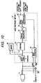
- Fig. 12 is a block diagram showing a system arrangement for displaying a plan view image.
- the image processing section 47 comprises an image selecting section 72 for selecting the images of designated cameras, a plan view image forming section 78 for producing a plan view image based on the selected images, and a view angle converting section 75 for converting the view angles of the door mirror cameras 14 and 15.
- the system control section 42 comprises a positional information detecting section 71 for detecting vehicle conditions based on the gear position information, the winker information, and the steering angle information. When the gear is shifted to the "back" position, the positional information detecting section 71 of the system control section 42 instructs the plan view image forming section 78 of the image processing section 47 to produce a plan view image.
- the positional information detecting section 71 instructs the image selecting section 72 to select the images taken by cameras 16, 17 and 18 in response to the driver's choice of the parking assist mode. Furthermore, when the column parking assist mode is chosen, the winker information and the steering angle information are referred to select the images taken by cameras 14, 16 and 18 for the left column parking or select the images taken by cameras 15, 17 and 18 for the right column parking. Furthermore, the positional information detecting section 71 instructs the view angle converting section 75 to enlarge the portion corresponding to the door mirror effective area in the images taken by the door mirror cameras 14 and 15.
- the enlarged image of the left door mirror camera 14, being processed in the view angle converting section 75, is displayed on the left view monitor 20 via a switching section 76.
- the enlarged image of the right door mirror camera 15, being processed in the view angle converting section 75, is displayed on the right view monitor 21 via a switching section 77.
- the plan view image produced from the plan view image forming section 78 is displayed on the main monitor 19.
- step 7 based on information of the vehicle speed signal 38, it is checked whether or not the vehicle speed is equal to or less than 8 km/h.
- step 7 When the vehicle speed is equal to or less than 8 km/h (i.e., Yes in step 7), it is assumed that the driver in the system vehicle intends to carefully watch the front or the sides. Thus, the control flow proceeds to a step 15.
- step 15 the main monitor 19 displays the joint image based on the images taken by the left lateral camera 12 and the right lateral camera 13.
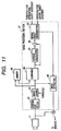
- Fig. 13 is a block diagram showing a system arrangement for displaying a joint image.
- the image processing section 47 comprises a joint image forming section 73 for producing a joint image in addition to the image selecting section 72 and the view angle converting section 75.
- the positional information detecting section 71 of the system control section 42 instructs the image selecting section 72 of the image processing section 47 to select the images taken by cameras 12 and 13.
- the positional information detecting section 71 instructs the joint image forming section 73 to produce a joint image consisting of the images taken by cameras 12 and 13.
- the positional information detecting section 71 informs the joint image forming section 73 of an image to be enlargedly displayed based on the gear position information.
- the joint image forming section 73 changes the display ratio of the images to be jointly displayed based on this instruction, and produces a modified joint image.
- the positional information detecting section 71 of the system control section 42 instructs the view angle converting section 75 to directly display the images taken by the door mirror cameras 14 and 15 without changing their display sizes.
- the wide angle image taken by the left door mirror camera 14 is displayed on the left view monitor 20 via the switching section 76.
- the wide angle image of the right door mirror camera 15 is displayed on the right view monitor 21 via the switching section 77.
- the joint image produced from the joint image forming section 73 is displayed on the main monitor 19.
- step 8 the view angles of the door mirror cameras 14 and 15 are narrowed so as to be equalized to the door mirror effective area.
- step 9 it is checked whether or not the vehicle speed is equal to or larger than 50 km/h.
- step 9 When the vehicle speed information indicates the speed equal to or larger than 50 km/h (i.e., Yes in step 9), the control flow proceeds to a step 10.
- step 10 based on the winker signal 40, it is checked whether or not the winker is turned on.
- step 10 When the winker is turned on (i.e., Yes in step 10), it is assumed that the driver intends to perform lane changing. The control flow proceeds to step 11.
- step 11 it is checked whether the winker signal 40 indicates left or right. When the winker signal 40 indicates left, the control flow proceeds to a step 12.
- step 12 the main monitor 19 displays a panorama image based on the images taken by the left pillar camera 16 and the rear camera 18.
- the winker signal 40 indicates right, the control flow proceeds to a step 13.
- step 13 the main monitor 19 displays a panorama image based on the images taken by the right pillar camera 17 and the rear camera 18.
- step 14 it is assumed that the system vehicle is in an ordinary traveling condition where the system vehicle substantially goes straight at a speed larger than 8 km/h.
- the main monitor 19 displays a panorama image based on the images taken by the left pillar camera 16, the rear camera 18, and the right pillar camera 17.
- step 9 When the vehicle speed is less than 50 km/h (i.e., No in step 9), the control flow proceeds to a step 16.
- step 16 based on the winker signal 40, it is checked whether or not the winker is turned on.
- step 16 When the winker is turned on (i.e., Yes in step 16), it is assumed that the driver intends to perform a turning or cornering operation of the system vehicle. In this case, to avoid any accident occurring at an inside of the turning or cornering vehicle, the control flow proceeds to a step 17.
- step 17 it is checked whether the winker signal 40 indicates left or right. When the winker signal 40 indicates left, the control flow proceeds to a step 18.
- step 18 the main monitor 19 displays a panorama image based on the images taken by the left door mirror camera 14 and the left pillar camera 16.
- the winker signal 40 indicates right, the control flow proceeds to a step 19.
- step 13 the main monitor 19 displays a panorama image based on the images taken by the right door mirror camera 15 and the right pillar camera 17.
- step 16 When the winker is turned off (i.e., Yes in step 16), the control flow proceeds to the step 14 in which the main monitor 19 displays a panorama image based on the images taken by the left pillar camera 16, the rear camera 18, and the right pillar camera 17.
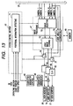
- Fig. 14 is a block diagram showing a system arrangement for displaying a panorama image.
- the image processing section 47 comprises a panorama image forming section 74 for producing a panorama image in addition to the image selecting section 72 and the view angle converting section 75.
- the positional information detecting section 71 of the system control section 42 instructs the image selecting section 72 of the image processing section 47 to select the images taken by cameras 16 and 18.
- the positional information detecting section 71 instructs the image selecting section 72 to select the images taken by cameras 17 and 18.
- the positional information detecting section 71 instructs the image selecting section 72 to select the images taken by cameras 14 and 16.
- the winker information or the steering angle information indicates the right turning or cornering operation
- the positional information detecting section 71 instructs the image selecting section 72 to select the images taken by cameras 15 and 17.
- the positional information detecting section 71 instructs the image selecting section 72 to select the images taken by cameras 16, 17 and 18.
- the positional information detecting section 71 instructs the panorama image forming section 74 to display a panorama image based on the images selected by the image selecting section 72.
- the positional information detecting section 71 instructs the view angle converting section 75 of the image processing section 47 to enlarge the portion corresponding to the door mirror effective area in the images taken by the door mirror cameras 14 and 15.
- the enlarged image of the left door mirror camera 14, being processed in the view angle converting section 75, is displayed on the left view monitor 20 via the switching section 76.
- the enlarged image of the right door mirror camera 15, being processed in the view angle converting section 75, is displayed on the right view monitor 21 via the switching section 77.
- the panorama image produced from the panorama image forming section 74 is displayed on the main monitor 19.
- this system makes it possible to adequately switch the display pattern of images in accordance with the steering angle signal 37, the vehicle speed signal 38, the gear position information 39, the winker signal 40 etc., thereby realizing the useful display of images to assist the safety driving.
- Fig. 15 is a block diagram showing a system arrangement for displaying a surrounding image based on a driver's instruction.
- the positional information detecting section 71 of the system control section 42 instructs the image selecting section 72 of the image processing section 47 to select the image of each camera designated by the driver via a jog controller 36. Furthermore, the positional information detecting section 71 instructs the joint image forming section 73 to combine the images selected by the image selecting section 72.
- the image selecting section 72 changes the image to be displayed in response to the directional change of the jog controller 36.
- the joint image forming section 73 produces a composite image. The resultant composite image is displayed on the left view monitor 20, the right view monitor 21, and the main monitor 19.
- the left view monitor 20 and the right view monitor 21 continuously display the images taken by the door mirror cameras 14 and 15, respectively.
- the above-described embodiment is based on the eight cameras mounted on the vehicle. However, it is possible to increase or decrease the total number of the cameras.
- the relationship between the vehicle conditions and the images to be displayed is not limited to the one disclosed in Fig. 2. Therefore, it is possible to variously change the relationship between the vehicle conditions and the images to be displayed.
- the multi-functional on-vehicle camera system and the related image display method it becomes possible to display the images for assisting the safety driving at an appropriate timing according to driving conditions. Furthermore, the present invention makes it possible to display the images in such a manner that the driver can easily grasp the circumferential conditions from the displayed image.
- Displaying the images in accordance with the present invention makes it possible for the driver to pay caution to circumferential conditions without any burden. This helps the driver avoiding any accident or trouble.
Abstract
Description
Claims (29)
- A multi-functional on-vehicle camera system comprising a plurality of cameras (11-18) mounted on a vehicle and a display unit (19-21) displaying at least one camera image,
characterized in thatimage processing means (47) is provided for processing images taken by said plurality of cameras, andsystem control means (42) is provided for selecting at least one camera image to be processed in said image processing means (47) from the images taken by said plurality of cameras (11-18) based on vehicle conditions (36-41), and for controlling a type of image processing performed in said image processing means (47). - The multi-functional on-vehicle camera system in accordance with claim 1, further comprising graphic superimposing means (45, 46) for superimposing a graphic pattern on said image processed by said image processing means (47),
wherein said system control means (42) controls both a type and a position of said graphic pattern superimposed by said graphic superimposing means (45, 46). - The multi-functional on-vehicle camera system in accordance with claim 1, wherein said plurality of cameras include at least two cameras selected from the group consisting of a rear camera (18) taking a rear view seen from the vehicle, right and left pillar cameras (16, 17) taking right and left rear side views seen from the vehicle, right and left door mirror cameras (14, 15) taking right and left door mirror views seen from the vehicle via right and left door mirrors, right and left lateral cameras (12, 13) taking front side views seen from the vehicle, and a front camera (11) taking a front view seen from the vehicle.
- The multi-functional on-vehicle camera system in accordance with claim 1, wherein said display unit includes a right monitor (21) displaying an image taken by a right door mirror camera (15), and a left monitor (20) displaying an image taken by a left door mirror camera (14).
- The multi-functional on-vehicle camera system in accordance with claim 1, wherein said image processing means (47) produces a plan view image based on images of a plurality of cameras (11-18), said plan view image including an image of the vehicle seen from above.
- The multi-functional on-vehicle camera system in accordance with claim 1, wherein said image processing means (47) produces a panorama image based on images of a plurality of cameras.
- The multi-functional on-vehicle camera system in accordance with claim 1, wherein said image processing means (47) produces a joint image by combining images of a plurality of cameras.
- The multi-functional on-vehicle camera system in accordance with claim 1, wherein said image processing means (47) produces a surrounding image representing a surrounding view seen from the vehicle by successively connecting images of all of said plurality of cameras mounted on the vehicle.
- The multi-functional on-vehicle camera system in accordance with claim 1, wherein said image processing means (47) produces an image formed by using part of image data obtained from said plurality of cameras.
- The multi-functional on-vehicle camera system in accordance with claim 1, wherein said image processing means (47) produces an image including a moving object approaching or leaving with respect to the vehicle, said moving object being emphasizing by a different color.
- The multi-functional on-vehicle camera system in accordance with claim 1, wherein said system control means (42) designates said camera image to be used in said image processing and designates the type of image processing performed in said image processing means (47) based on at least one signal representing vehicle conditions selected from the group consisting of a steering angle signal (37), a vehicle speed signal (38), gear position information (39) and winker information (40).
- The multi-functional on-vehicle camera system in accordance with claim 2, wherein said graphic superimposing means (45, 46) superimposes a graphic pattern of a moving object approaching or leaving with respect to the vehicle.
- An image display method for a multi-functional on-vehicle camera system comprising a plurality of cameras (11-18) mounted on a vehicle and a display unit (19-21) displaying at least one camera image, said image display method comprising the steps of:processing at least one camera image selected from a plurality of images obtained from said plurality of cameras based on vehicle conditions, anddisplaying a processed camera image on said display unit.
- The image display method for a multi-functional on-vehicle camera system in accordance with claim 13, whereinsaid plurality of cameras (11-18) include at least two cameras selected from the group consisting of a rear camera (18) taking a rear view seen from the vehicle, right and left pillar cameras (16, 17) taking right and left rear side views seen from the vehicle, right and left door mirror cameras (14, 15) taking right and left door mirror views seen from the vehicle via right and left door mirrors, right and left lateral cameras (12, 13) taking side views seen from the vehicle, and a front camera (11) taking a front view seen from the vehicle, andimages of said at least two cameras are processed in image processing means (47) and displayed on said display unit (19-21).
- The image display method for a multi-functional on-vehicle camera system in accordance with claim 14, whereina plan view image is produced and displayed based on at least three images of said rear camera (18) and said right and left pillar cameras (16, 17) when said vehicle moves backward for parking, said plan view image including a view of the vehicle seen from above (step 3).
- The image display method for a multi-functional on-vehicle camera system in accordance with claim 14, whereina plan view image is produced and displayed based on at least three images of said rear camera (18), said left pillar camera (16) and said left door mirror camera (14) when said vehicle moves backward for parking along a left side of a road, said plan view image including a view of the vehicle seen from above (step 5).
- The image display method for a multi-functional on-vehicle camera system in accordance with claim 14, whereina plan view image is produced and displayed based on at least three images of said rear camera (18), said right pillar camera (17) and said right door mirror camera (15) when said vehicle moves backward for parking along a right side of a road, said plan view image including a view of the vehicle seen from above (step 6).
- The image display method for a multi-functional on-vehicle camera system in accordance with claim 14, whereina panorama image is produced and displayed by combining at least two images of said left door camera (14) and said left pillar camera (16) when said vehicle turns left, thereby eliminating an accident occurring at an inside of the vehicle during a left turning or cornering operation (step 18).
- The image display method for a multi-functional on-vehicle camera system in accordance with claim 14, whereina panorama image is produced and displayed by combining at least two images of said right door camera (15) and said right pillar camera (17) when said vehicle turns right, thereby eliminating an accident occurring at an inside of the vehicle during a right turning or cornering operation (step 19).
- The image display method for a multi-functional on-vehicle camera system in accordance with claim 14, whereina panorama image is produced and displayed by combining at least two images of said left pillar camera (16) and said rear camera (18) when said vehicle performs lane changing to a left lane (step 12).
- The image display method for a multi-functional on-vehicle camera system in accordance with claim 14, whereina panorama image is produced and displayed by combining at least two images of said right pillar camera (17) and said rear camera (18) when said vehicle performs lane changing to a right lane (step 13).
- The image display method for a multi-functional on-vehicle camera system in accordance with claim 14, wherein said display unit includes a right monitor (21) displaying an image taken by said right door mirror camera (15) and a left monitor (20) displaying an image taken by said left door mirror camera (14).
- The image display method for a multi-functional on-vehicle camera system in accordance with claim 22, wherein each of said right and left monitors (21, 20) displays a limited image seen within a view angle of a corresponding door mirror when said vehicle is traveling (Fig. 7).
- The image display method for a multi-functional on-vehicle camera system in accordance with claim 14, whereina panorama image is produced and displayed by combining three images of said right and left pillar cameras (16, 17) and said rear camera (18) when said vehicle is traveling ordinarily (step 14).
- The image display method for a multi-functional on-vehicle camera system in accordance with claim 14, whereina joint image is produced and displayed by combining two images of said right and left lateral cameras (12, 13) when said vehicle is traveling slowly or stopped for confirmation of forward or side obstacles (Step 15).
- The image display method for a multi-functional on-vehicle camera system in accordance with claim 25, whereinthe image of said right lateral camera (12) is enlarged when said vehicle turns right, and the image of said left lateral camera (13) is enlarged when said vehicle turns left (Fig. 9).
- The image display method for a multi-functional on-vehicle camera system in accordance with any one of claims 13 to 26, whereinthe image displayed on said display unit includes a moving object approaching or leaving with respect to the vehicle, said object being emphasizing by a different color.
- The image display method for a multi-functional on-vehicle camera system in accordance with any one of claims 13 to 26, whereina graphic pattern is superimposed on the displayed image, said graphic pattern representing a moving object approaching or leaving with respect to the vehicle.
- The image display method for a multi-functional on-vehicle camera system in accordance with claim 22, whereinthe image taken by said door mirror camera (14, 15) is continuously displayed when any passenger is in the vehicle.
Applications Claiming Priority (2)
| Application Number | Priority Date | Filing Date | Title |
|---|---|---|---|
| JP23165299 | 1999-08-18 | ||
| JP23165299A JP3298851B2 (en) | 1999-08-18 | 1999-08-18 | Multi-function vehicle camera system and image display method of multi-function vehicle camera |
Publications (3)
| Publication Number | Publication Date |
|---|---|
| EP1077161A2 true EP1077161A2 (en) | 2001-02-21 |
| EP1077161A3 EP1077161A3 (en) | 2004-04-07 |
| EP1077161B1 EP1077161B1 (en) | 2006-02-08 |
Family
ID=16926860
Family Applications (1)
| Application Number | Title | Priority Date | Filing Date |
|---|---|---|---|
| EP00117542A Expired - Lifetime EP1077161B1 (en) | 1999-08-18 | 2000-08-14 | Multi-functional on-vehicle camera system and image display method for the same |
Country Status (5)
| Country | Link |
|---|---|
| US (1) | US6593960B1 (en) |
| EP (1) | EP1077161B1 (en) |
| JP (1) | JP3298851B2 (en) |
| CN (1) | CN1174623C (en) |
| DE (1) | DE60025864T2 (en) |
Cited By (28)
| Publication number | Priority date | Publication date | Assignee | Title |
|---|---|---|---|---|
| WO2003034738A1 (en) | 2001-10-10 | 2003-04-24 | Matsushita Electric Industrial Co., Ltd. | Image processor |
| WO2003084232A1 (en) * | 2002-03-28 | 2003-10-09 | Bendix Commercial Vehicle Systems Llc | An integrated video/data information system and method for application to commercial vehicles to enhance driver awareness |
| WO2004035352A1 (en) * | 2002-10-15 | 2004-04-29 | Tae-Soon Yeo | Omnidirectional watching system for vehicle |
| EP1312506A3 (en) * | 2001-11-07 | 2004-05-06 | C.R.F. Società Consortile per Azioni | A method and system for assisting the driver of a motor vehicle in a lane-change manoeuvre |
| EP1434441A1 (en) * | 2001-09-28 | 2004-06-30 | Matsushita Electric Industrial Co., Ltd. | Drive support display apparatus |
| WO2005084028A2 (en) * | 2004-02-26 | 2005-09-09 | Bendix Commercial Vehicle Systems Llc | Vehicle video processing system |
| EP1610554A2 (en) * | 2004-06-24 | 2005-12-28 | Magna Donnelly GmbH & Co. KG | Vehicle with identification of the source of image data |
| EP1625975A1 (en) * | 2003-05-22 | 2006-02-15 | Clarion Co., Ltd. | Vehicle-mounted display controller, vehicle-mounted display unit, display control method, control program, and recording medium |
| EP1646240A1 (en) * | 2003-07-11 | 2006-04-12 | Hitachi, Ltd. | Image processing camera system and image processing camera control method |
| DE102004048185A1 (en) * | 2004-09-30 | 2006-04-27 | Magna Donnelly Gmbh & Co. Kg | Method for operating an electronic inspection system and vehicle with an electronic inspection system |
| WO2009132617A1 (en) * | 2008-04-29 | 2009-11-05 | Magna Electronics Europe Gmbh & Co. Kg | Device and method for detecting and displaying the rear and/or side view of a motor vehicle |
| EP2228259A1 (en) * | 2009-03-11 | 2010-09-15 | Delphi Technologies, Inc. | Sideview Vision System displaying a view dependent upon transmission selector |
| WO2011047732A1 (en) * | 2009-10-22 | 2011-04-28 | Tele Atlas B.V. | Method for identifying moving foreground objects in an orthorectified photographic image |
| CN102186701A (en) * | 2008-10-20 | 2011-09-14 | 萨班哲大学 | A vehicle camera |
| CN102673475A (en) * | 2011-03-10 | 2012-09-19 | 现代摩比斯株式会社 | Anti-collision parking assistance device and method |
| EP2623374A1 (en) | 2012-01-31 | 2013-08-07 | MEKRA Lang GmbH & Co. KG | Vision system for commercial vehicles for the display of the statutory fields of view of a main mirror and a wide-angle mirror |
| CN103863192A (en) * | 2014-04-03 | 2014-06-18 | 深圳市德赛微电子技术有限公司 | Method and system for vehicle-mounted panoramic imaging assistance |
| CN104163133A (en) * | 2013-05-16 | 2014-11-26 | 福特环球技术公司 | Rear view camera system using rear view mirror location |
| US9230300B2 (en) | 2009-10-22 | 2016-01-05 | Tim Bekaert | Method for creating a mosaic image using masks |
| EP2394854A3 (en) * | 2010-06-09 | 2016-05-04 | Delphi Technologies, Inc. | All-around parking assisting system |
| CN106687332A (en) * | 2014-09-17 | 2017-05-17 | 松下知识产权经营株式会社 | Electronic mirror device |
| KR20180097613A (en) * | 2015-12-28 | 2018-08-31 | 스미토모 겐키 가부시키가이샤 | Shovel |
| EP3460403A1 (en) * | 2017-09-26 | 2019-03-27 | LG Electronics Inc. | Method for controlling operation system of a vehicle |
| EP3505398A1 (en) * | 2017-12-27 | 2019-07-03 | Toyota Jidosha Kabushiki Kaisha | Image display apparatus |
| CN111372045A (en) * | 2020-02-28 | 2020-07-03 | 浙江维尔科技有限公司 | Method for supervising training video of motor vehicle driver |
| EP3550819A4 (en) * | 2016-11-30 | 2020-07-15 | KYOCERA Corporation | Camera and monitor system, image processing device, vehicle, and image processing method |
| EP3978296A1 (en) * | 2020-10-05 | 2022-04-06 | Continental Automotive GmbH | Motor vehicle display system and method |
| DE102016213045B4 (en) | 2015-12-08 | 2022-06-09 | Hyundai Motor Company | SYSTEM AND METHOD FOR PROVIDING IMAGE INFORMATION OF A VEHICLE ENVIRONMENT |
Families Citing this family (226)
| Publication number | Priority date | Publication date | Assignee | Title |
|---|---|---|---|---|
| US6822563B2 (en) | 1997-09-22 | 2004-11-23 | Donnelly Corporation | Vehicle imaging system with accessory control |
| US5877897A (en) | 1993-02-26 | 1999-03-02 | Donnelly Corporation | Automatic rearview mirror, vehicle lighting control and vehicle interior monitoring system using a photosensor array |
| US6891563B2 (en) | 1996-05-22 | 2005-05-10 | Donnelly Corporation | Vehicular vision system |
| US7655894B2 (en) | 1996-03-25 | 2010-02-02 | Donnelly Corporation | Vehicular image sensing system |
| US6326613B1 (en) | 1998-01-07 | 2001-12-04 | Donnelly Corporation | Vehicle interior mirror assembly adapted for containing a rain sensor |
| US6124886A (en) | 1997-08-25 | 2000-09-26 | Donnelly Corporation | Modular rearview mirror assembly |
| US6445287B1 (en) | 2000-02-28 | 2002-09-03 | Donnelly Corporation | Tire inflation assistance monitoring system |
| US6278377B1 (en) | 1999-08-25 | 2001-08-21 | Donnelly Corporation | Indicator for vehicle accessory |
| US6420975B1 (en) | 1999-08-25 | 2002-07-16 | Donnelly Corporation | Interior rearview mirror sound processing system |
| JP3575346B2 (en) * | 1999-09-03 | 2004-10-13 | 日本電気株式会社 | Road white line detection system, road white line detection method, and recording medium recording road white line detection program |
| US7480149B2 (en) | 2004-08-18 | 2009-01-20 | Donnelly Corporation | Accessory module for vehicle |
| EP1263626A2 (en) | 2000-03-02 | 2002-12-11 | Donnelly Corporation | Video mirror systems incorporating an accessory module |
| DE10013425A1 (en) * | 2000-03-17 | 2001-09-27 | Bosch Gmbh Robert | Vehicle-mounted camera support selectively extended out from automobile body for viewing area immediately adjacent automobile |
| JP2002083285A (en) * | 2000-07-07 | 2002-03-22 | Matsushita Electric Ind Co Ltd | Image compositing device and image compositing method |
| SE520042C2 (en) * | 2000-10-26 | 2003-05-13 | Autoliv Dev | Device for improving the night vision of a vehicle such as a car |
| US20030202097A1 (en) * | 2000-10-26 | 2003-10-30 | Autoliv Development Ab | Night vision arrangement |
| JP2002359839A (en) | 2001-03-29 | 2002-12-13 | Matsushita Electric Ind Co Ltd | Method and device for displaying image of rearview camera |
| US7183944B2 (en) * | 2001-06-12 | 2007-02-27 | Koninklijke Philips Electronics N.V. | Vehicle tracking and identification of emergency/law enforcement vehicles |
| JP4512293B2 (en) * | 2001-06-18 | 2010-07-28 | パナソニック株式会社 | Monitoring system and monitoring method |
| JP3960092B2 (en) * | 2001-07-12 | 2007-08-15 | 日産自動車株式会社 | Image processing apparatus for vehicle |
| US7697027B2 (en) | 2001-07-31 | 2010-04-13 | Donnelly Corporation | Vehicular video system |
| JP3947375B2 (en) * | 2001-08-24 | 2007-07-18 | アイシン精機株式会社 | Parking assistance device |
| JP4658408B2 (en) * | 2001-08-30 | 2011-03-23 | 株式会社東海理化電機製作所 | Vehicle monitoring device |
| US20040212484A1 (en) * | 2001-09-04 | 2004-10-28 | Exon Science Inc. | Control device and method for automatically adjusting view angle of rearview angle of outside camera in response to output of navigation system |
| US6672728B1 (en) * | 2001-09-04 | 2004-01-06 | Exon Science Inc. | Exterior rearview mirror with automatically adjusted view angle |
| US7012510B2 (en) * | 2001-09-04 | 2006-03-14 | Exon Science Inc. | Device and method for adjusting view range of vehicular monitoring device |
| US20030146828A1 (en) * | 2001-09-04 | 2003-08-07 | Exon Science Inc. | Control module for adjusting view angle of rearview mirror via vehicular digital bus |
| JP4769397B2 (en) * | 2001-09-28 | 2011-09-07 | クラリオン株式会社 | In-vehicle information equipment |
| KR100866450B1 (en) | 2001-10-15 | 2008-10-31 | 파나소닉 주식회사 | Automobile surrounding observation device and method for adjusting the same |
| US7995095B2 (en) * | 2001-10-18 | 2011-08-09 | Autoliv Development Ab | Night vision device for a vehicle |
| JP3607994B2 (en) * | 2001-11-12 | 2005-01-05 | トヨタ自動車株式会社 | Vehicle periphery monitoring device |
| US6824281B2 (en) | 2002-01-31 | 2004-11-30 | Donnelly Corporation | Vehicle accessory module |
| AUPS047502A0 (en) * | 2002-02-13 | 2002-03-07 | Silverbrook Research Pty. Ltd. | Methods and systems (ap66) |
| JP4195966B2 (en) * | 2002-03-05 | 2008-12-17 | パナソニック株式会社 | Image display control device |
| JP3855814B2 (en) * | 2002-03-22 | 2006-12-13 | 日産自動車株式会社 | Image processing apparatus for vehicle |
| KR100475960B1 (en) * | 2002-04-18 | 2005-03-10 | 기아자동차주식회사 | Apparatus for Recognizing the Rear of Vehicle |
| ES2391556T3 (en) | 2002-05-03 | 2012-11-27 | Donnelly Corporation | Object detection system for vehicles |
| US20030227424A1 (en) * | 2002-06-05 | 2003-12-11 | Lynch Marvin L. | Method and apparatus for in-vehicle traffic flow viewing |
| US20030227546A1 (en) * | 2002-06-06 | 2003-12-11 | Hilborn Thomas W. | Viewing arrangement |
| US20060061008A1 (en) | 2004-09-14 | 2006-03-23 | Lee Karner | Mounting assembly for vehicle interior mirror |
| AU2003244949A1 (en) * | 2002-07-25 | 2004-02-16 | Koninklijke Philips Electronics N.V. | Viewing system |
| JP3898104B2 (en) * | 2002-08-30 | 2007-03-28 | 株式会社オートネットワーク技術研究所 | Vehicle periphery monitoring device |
| US7353086B2 (en) * | 2002-11-19 | 2008-04-01 | Timothy James Ennis | Methods and systems for providing a rearward field of view for use with motorcycles |
| JP2004173071A (en) * | 2002-11-21 | 2004-06-17 | Auto Network Gijutsu Kenkyusho:Kk | Vehicle periphery monitoring device |
| US7355628B2 (en) * | 2002-12-20 | 2008-04-08 | Bendix Commercial Vehicle Systems Llc | Method and apparatus of maintaining a video signal through brief interruptions of a related control signal |
| JP4427953B2 (en) * | 2003-01-29 | 2010-03-10 | 株式会社豊田自動織機 | Parking assistance device |
| DE10304703B4 (en) * | 2003-02-06 | 2023-03-16 | Bayerische Motoren Werke Aktiengesellschaft | Method and device for visualizing the environment of a vehicle with environment-dependent fusion of an infrared and a visual image |
| US6930593B2 (en) * | 2003-02-24 | 2005-08-16 | Iteris, Inc. | Lane tracking system employing redundant image sensing devices |
| JP2004312638A (en) * | 2003-04-10 | 2004-11-04 | Mitsubishi Electric Corp | Obstacle detection apparatus |
| JP4700899B2 (en) * | 2003-04-14 | 2011-06-15 | 株式会社豊田自動織機 | Parking assistance device |
| JP4218453B2 (en) * | 2003-07-15 | 2009-02-04 | 株式会社デンソー | Vehicle forward visibility support device |
| JP2005062992A (en) * | 2003-08-08 | 2005-03-10 | Nissan Motor Co Ltd | Image generating device and view angle converting means and view angle converting program |
| JP2005099572A (en) * | 2003-09-26 | 2005-04-14 | Chuo Electronics Co Ltd | Wide range photographing method and display method |
| US7172300B2 (en) * | 2003-11-10 | 2007-02-06 | Morgan Plaster | Driver observation system |
| US7730814B2 (en) * | 2004-01-26 | 2010-06-08 | Nec Corporation | Video image type determination system, video image processing system, video image processing method and video image processing program |
| JP4457690B2 (en) * | 2004-02-18 | 2010-04-28 | 日産自動車株式会社 | Driving assistance device |
| US7466338B2 (en) * | 2004-02-26 | 2008-12-16 | Yiling Xie | Wide-angled image display system for automobiles |
| DE102004011198A1 (en) * | 2004-03-04 | 2005-09-15 | Daimlerchrysler Ag | Displaying ambient information acquired by one or more cameras in motor vehicle involves using color of background coloring dependent on whether image is being indicated in direction of travel or anticipated direction of travel |
| JP2005278040A (en) * | 2004-03-26 | 2005-10-06 | Alpine Electronics Inc | Display device and method for indicating display direction |
| US7526103B2 (en) | 2004-04-15 | 2009-04-28 | Donnelly Corporation | Imaging system for vehicle |
| JP2005311698A (en) * | 2004-04-21 | 2005-11-04 | Auto Network Gijutsu Kenkyusho:Kk | Vehicle periphery visually recognizing apparatus |
| JP2005333565A (en) * | 2004-05-21 | 2005-12-02 | Auto Network Gijutsu Kenkyusho:Kk | Monitoring equipment |
| EP1768866B1 (en) * | 2004-06-07 | 2013-04-24 | Sharp Kabushiki Kaisha | Display system for vehicle and vehicle |
| WO2005124735A1 (en) * | 2004-06-18 | 2005-12-29 | Nec Corporation | Image display system, image display method, and image display program |
| EP1771811A4 (en) * | 2004-07-26 | 2010-06-09 | Silicon Optix Inc | Panoramic vision system and method |
| JP2006050246A (en) * | 2004-08-04 | 2006-02-16 | Auto Network Gijutsu Kenkyusho:Kk | Device for visually recognizing around vehicle |
| JP2006054662A (en) * | 2004-08-11 | 2006-02-23 | Mitsubishi Electric Corp | Drive support device |
| US20060061655A1 (en) * | 2004-09-22 | 2006-03-23 | Chih-Yuan Wang | Auxiliary braking light with a camera device |
| JP3977368B2 (en) * | 2004-09-30 | 2007-09-19 | クラリオン株式会社 | Parking assistance system |
| JP4573242B2 (en) * | 2004-11-09 | 2010-11-04 | アルパイン株式会社 | Driving assistance device |
| US7422337B1 (en) | 2004-11-23 | 2008-09-09 | David Eugene Fetherston | Rear-view safety mirrors |
| JP2006160193A (en) * | 2004-12-10 | 2006-06-22 | Alpine Electronics Inc | Vehicular drive supporting device |
| EP1827908B1 (en) | 2004-12-15 | 2015-04-29 | Magna Electronics Inc. | An accessory module system for a vehicle window |
| JP2006213071A (en) * | 2005-02-01 | 2006-08-17 | Nippon Seiki Co Ltd | Vehicular monitoring device |
| JP2006240383A (en) * | 2005-03-01 | 2006-09-14 | National Univ Corp Shizuoka Univ | Cruising assist on-vehicle information system |
| JP4432801B2 (en) * | 2005-03-02 | 2010-03-17 | 株式会社デンソー | Driving assistance device |
| JP2006273308A (en) * | 2005-03-03 | 2006-10-12 | National Univ Corp Shizuoka Univ | Visual information provision system |
| WO2006100884A1 (en) * | 2005-03-18 | 2006-09-28 | Pioneer Corporation | Video display device, video display method, video display program, and computer-readable recording medium having the program recorded thereon |
| JP4645254B2 (en) * | 2005-03-24 | 2011-03-09 | アイシン・エィ・ダブリュ株式会社 | Vehicle periphery visual recognition device |
| US8130269B2 (en) | 2005-03-23 | 2012-03-06 | Aisin Aw Co., Ltd. | Visual recognition apparatus, methods, and programs for vehicles |
| JP2008179940A (en) * | 2005-03-31 | 2008-08-07 | Hitachi Constr Mach Co Ltd | Surrounding monitoring equipment of working machine |
| JP2006311272A (en) * | 2005-04-28 | 2006-11-09 | Denso Corp | Video display device for vehicle |
| JP4882285B2 (en) * | 2005-06-15 | 2012-02-22 | 株式会社デンソー | Vehicle travel support device |
| DE102005030838A1 (en) * | 2005-07-01 | 2007-01-04 | Siemens Ag | Night Vision System |
| US20070019311A1 (en) * | 2005-07-22 | 2007-01-25 | Doron Precision Systems, Inc. | Semi-interactive driving simulator with multiple simulated mirror images and method of preparing images for use in simulator |
| JP4815943B2 (en) * | 2005-08-19 | 2011-11-16 | 株式会社デンソー | Hazardous area information display device |
| JP4809019B2 (en) * | 2005-08-31 | 2011-11-02 | クラリオン株式会社 | Obstacle detection device for vehicle |
| JP2007110177A (en) * | 2005-10-10 | 2007-04-26 | Denso Corp | Image processing apparatus and program |
| JP4971625B2 (en) * | 2005-11-14 | 2012-07-11 | 富士通テン株式会社 | Driving support device and driving information calculation system |
| JP2007142624A (en) * | 2005-11-16 | 2007-06-07 | Matsushita Electric Ind Co Ltd | Vehicle mounted imaging apparatus |
| JP4780385B2 (en) * | 2005-11-17 | 2011-09-28 | アイシン精機株式会社 | Perimeter monitoring system |
| JP4611898B2 (en) * | 2006-01-12 | 2011-01-12 | アルパイン株式会社 | Image display system |
| DE102006003538B3 (en) * | 2006-01-24 | 2007-07-19 | Daimlerchrysler Ag | Image acquisitions merging method for bird`s eye perspective, involves selecting image sections such that shadowing effects produced by moved objects are projected during transition in overall image from image section to other section |
| US8698894B2 (en) | 2006-02-07 | 2014-04-15 | Magna Electronics Inc. | Camera mounted at rear of vehicle |
| JP4707109B2 (en) * | 2006-03-02 | 2011-06-22 | アルパイン株式会社 | Multi-camera image processing method and apparatus |
| US20070233361A1 (en) * | 2006-03-30 | 2007-10-04 | Ford Global Technologies, Llc | Centralized Image Processing For An Automobile With A Navigation System |
| JP2007304407A (en) * | 2006-05-12 | 2007-11-22 | Alpine Electronics Inc | Automatic exposure device and method for vehicle-mounted camera |
| JP4812510B2 (en) * | 2006-05-17 | 2011-11-09 | アルパイン株式会社 | Vehicle peripheral image generation apparatus and photometric adjustment method for imaging apparatus |
| US8139109B2 (en) * | 2006-06-19 | 2012-03-20 | Oshkosh Corporation | Vision system for an autonomous vehicle |
| US8947531B2 (en) * | 2006-06-19 | 2015-02-03 | Oshkosh Corporation | Vehicle diagnostics based on information communicated between vehicles |
| JP4855158B2 (en) * | 2006-07-05 | 2012-01-18 | 本田技研工業株式会社 | Driving assistance device |
| JP4254887B2 (en) * | 2006-07-06 | 2009-04-15 | 日産自動車株式会社 | Image display system for vehicles |
| JP4982127B2 (en) * | 2006-07-19 | 2012-07-25 | クラリオン株式会社 | Image display system |
| JP4882571B2 (en) * | 2006-07-20 | 2012-02-22 | 日産自動車株式会社 | Vehicle monitoring device |
| WO2008024639A2 (en) | 2006-08-11 | 2008-02-28 | Donnelly Corporation | Automatic headlamp control system |
| US7728879B2 (en) * | 2006-08-21 | 2010-06-01 | Sanyo Electric Co., Ltd. | Image processor and visual field support device |
| KR100775105B1 (en) * | 2006-09-06 | 2007-11-08 | 이동욱 | Safe external watching dual monitor system for vehicles |
| JP5070809B2 (en) * | 2006-11-10 | 2012-11-14 | アイシン精機株式会社 | Driving support device, driving support method, and program |
| JP4420011B2 (en) * | 2006-11-16 | 2010-02-24 | 株式会社日立製作所 | Object detection device |
| JP2007099275A (en) * | 2007-01-22 | 2007-04-19 | Setsuo Kuroki | Mobile monitor body for in-cabin front upper part |
| JP4977482B2 (en) * | 2007-01-25 | 2012-07-18 | 三洋電機株式会社 | Image providing apparatus, vehicle, and image providing method |
| JP4882777B2 (en) * | 2007-02-13 | 2012-02-22 | 株式会社デンソー | Lane change support device and program |
| GB2447672B (en) | 2007-03-21 | 2011-12-14 | Ford Global Tech Llc | Vehicle manoeuvring aids |
| JP5003946B2 (en) * | 2007-05-30 | 2012-08-22 | アイシン精機株式会社 | Parking assistance device |
| US8233045B2 (en) * | 2007-07-16 | 2012-07-31 | Trw Automotive U.S. Llc | Method and apparatus for distortion correction and image enhancing of a vehicle rear viewing system |
| JP2009087228A (en) * | 2007-10-02 | 2009-04-23 | Denso Corp | Image display device |
| EP2062778B1 (en) * | 2007-11-23 | 2013-07-31 | SMR Patents S.à.r.l. | Lane Change Control System |
| TWI361396B (en) * | 2008-01-18 | 2012-04-01 | Univ Nat Chiao Tung | Image synthesis system for a vehicle and the manufacturing method thereof mage synthesis device and method |
| EP2253131B1 (en) | 2008-02-08 | 2014-06-25 | Google, Inc. | Panoramic camera with multiple image sensors using timed shutters |
| US9123241B2 (en) | 2008-03-17 | 2015-09-01 | International Business Machines Corporation | Guided video feed selection in a vehicle-to-vehicle network |
| US9043483B2 (en) * | 2008-03-17 | 2015-05-26 | International Business Machines Corporation | View selection in a vehicle-to-vehicle network |
| US8345098B2 (en) * | 2008-03-17 | 2013-01-01 | International Business Machines Corporation | Displayed view modification in a vehicle-to-vehicle network |
| US8400507B2 (en) * | 2008-03-17 | 2013-03-19 | International Business Machines Corporation | Scene selection in a vehicle-to-vehicle network |
| JP2009225322A (en) * | 2008-03-18 | 2009-10-01 | Hyundai Motor Co Ltd | Vehicle information display system |
| JP4999748B2 (en) * | 2008-03-28 | 2012-08-15 | 株式会社エクォス・リサーチ | Side mirror device |
| JP2008278526A (en) * | 2008-06-16 | 2008-11-13 | Panasonic Corp | Drive support image generator |
| JP5168213B2 (en) * | 2009-04-02 | 2013-03-21 | 株式会社デンソー | Display device |
| JP4528867B1 (en) * | 2009-05-15 | 2010-08-25 | 株式会社東芝 | Image processing apparatus, image processing method, and display apparatus |
| JP5087051B2 (en) | 2009-07-02 | 2012-11-28 | 富士通テン株式会社 | Image generating apparatus and image display system |
| JP5226621B2 (en) * | 2009-07-06 | 2013-07-03 | 東芝アルパイン・オートモティブテクノロジー株式会社 | Image display device for vehicle |
| JP5209578B2 (en) * | 2009-07-28 | 2013-06-12 | 東芝アルパイン・オートモティブテクノロジー株式会社 | Image display device for vehicle |
| JP5436086B2 (en) * | 2009-08-03 | 2014-03-05 | アルパイン株式会社 | Vehicle periphery image display device and vehicle periphery image display method |
| US8988525B2 (en) * | 2009-08-27 | 2015-03-24 | Robert Bosch Gmbh | System and method for providing guidance information to a driver of a vehicle |
| WO2011030699A1 (en) * | 2009-09-11 | 2011-03-17 | アイシン精機株式会社 | Device for monitoring surroundings of vehicle |
| US8502860B2 (en) * | 2009-09-29 | 2013-08-06 | Toyota Motor Engineering & Manufacturing North America (Tema) | Electronic control system, electronic control unit and associated methodology of adapting 3D panoramic views of vehicle surroundings by predicting driver intent |
| US20110080482A1 (en) * | 2009-10-06 | 2011-04-07 | Wen-Ching Shih | Monitor-displayed device for car rear vision |
| DE102010020201B4 (en) * | 2009-11-06 | 2021-08-26 | Volkswagen Ag | Method and device for displaying the images of a rearview camera system of a motor vehicle |
| JP5360491B2 (en) * | 2009-11-13 | 2013-12-04 | アイシン精機株式会社 | Multifunctional camera system |
| JP2011131678A (en) * | 2009-12-24 | 2011-07-07 | Fujitsu Ten Ltd | Image processing device, image processing system and image processing method |
| TW201125766A (en) * | 2010-01-27 | 2011-08-01 | Hon Hai Prec Ind Co Ltd | Car |
| CN102139664A (en) * | 2010-01-29 | 2011-08-03 | 鸿富锦精密工业(深圳)有限公司 | Automobile |
| KR100959347B1 (en) * | 2010-02-24 | 2010-05-20 | 조성호 | An apparatus furnishing left-right-rear side view of vehicles |
| DE102010011496A1 (en) * | 2010-03-16 | 2011-09-22 | GM Global Technology Operations LLC , (n. d. Ges. d. Staates Delaware) | Method for selectively displaying information of a camera system in a display device of a vehicle and vehicle with a camera system |
| CN201792814U (en) * | 2010-06-09 | 2011-04-13 | 德尔福技术有限公司 | Omnibearing parking auxiliary system |
| JP5251947B2 (en) * | 2010-09-17 | 2013-07-31 | 日産自動車株式会社 | Image display device for vehicle |
| US8459619B2 (en) | 2010-10-24 | 2013-06-11 | Oshkosh Corporation | Gas spring control system and method |
| US9264672B2 (en) | 2010-12-22 | 2016-02-16 | Magna Mirrors Of America, Inc. | Vision display system for vehicle |
| JP2012142832A (en) * | 2011-01-05 | 2012-07-26 | Seiko Epson Corp | Imaging apparatus |
| WO2012127576A1 (en) * | 2011-03-18 | 2012-09-27 | トヨタ自動車株式会社 | Vehicle periphery monitoring device |
| KR101778677B1 (en) * | 2011-04-08 | 2017-09-15 | 현대모비스 주식회사 | Smart control method for outputting parking trace |
| JP2012226392A (en) * | 2011-04-14 | 2012-11-15 | Honda Elesys Co Ltd | Drive support system |
| US9926008B2 (en) | 2011-04-19 | 2018-03-27 | Ford Global Technologies, Llc | Trailer backup assist system with waypoint selection |
| US9854209B2 (en) | 2011-04-19 | 2017-12-26 | Ford Global Technologies, Llc | Display system utilizing vehicle and trailer dynamics |
| US9834153B2 (en) | 2011-04-25 | 2017-12-05 | Magna Electronics Inc. | Method and system for dynamically calibrating vehicular cameras |
| CN102985945B (en) * | 2011-06-02 | 2016-09-07 | 松下知识产权经营株式会社 | Article detection device, object detecting method |
| KR101316231B1 (en) * | 2011-07-26 | 2013-10-08 | 엘지이노텍 주식회사 | Multi-image processing apparatus |
| US9491451B2 (en) | 2011-11-15 | 2016-11-08 | Magna Electronics Inc. | Calibration system and method for vehicular surround vision system |
| KR101265711B1 (en) * | 2011-11-30 | 2013-05-20 | 주식회사 이미지넥스트 | 3d vehicle around view generating method and apparatus |
| WO2013086249A2 (en) | 2011-12-09 | 2013-06-13 | Magna Electronics, Inc. | Vehicle vision system with customized display |
| WO2013126715A2 (en) | 2012-02-22 | 2013-08-29 | Magna Electronics, Inc. | Vehicle camera system with image manipulation |
| KR101877570B1 (en) * | 2012-04-04 | 2018-07-11 | 현대자동차주식회사 | Apparatus for setting parking position based on around view image and method thereof |
| US9751465B2 (en) | 2012-04-16 | 2017-09-05 | Magna Electronics Inc. | Vehicle vision system with reduced image color data processing by use of dithering |
| TW201344648A (en) * | 2012-04-30 | 2013-11-01 | Tung Thih Electronic Co Ltd | Driving monitoring system and driving monitoring method |
| US9738223B2 (en) * | 2012-05-31 | 2017-08-22 | GM Global Technology Operations LLC | Dynamic guideline overlay with image cropping |
| CN102774324B (en) * | 2012-07-06 | 2014-12-10 | 广东好帮手电子科技股份有限公司 | Panoramic parking assist system and implementation method thereof |
| DE102012215322A1 (en) * | 2012-08-29 | 2014-03-06 | Robert Bosch Gmbh | Method and device for detecting a position of a vehicle on a lane |
| KR101366112B1 (en) * | 2012-09-04 | 2014-02-24 | 전자부품연구원 | Avm system of vehicle for dividing and managing camera networks and avm method thereof |
| JP5466743B2 (en) * | 2012-09-06 | 2014-04-09 | 富士通テン株式会社 | Image generating apparatus and image display system |
| CN102795167A (en) * | 2012-09-07 | 2012-11-28 | 李超 | Built-in camera device for automobile lamp |
| CN102874176A (en) * | 2012-10-25 | 2013-01-16 | 四川大学 | Method for observing side surfaces and front and back parts of vehicle |
| KR102001659B1 (en) * | 2012-11-19 | 2019-07-19 | 한국전자통신연구원 | Method and apparatus for providing camera calibration for vehicles |
| US9743002B2 (en) | 2012-11-19 | 2017-08-22 | Magna Electronics Inc. | Vehicle vision system with enhanced display functions |
| DE102012025322B4 (en) * | 2012-12-22 | 2014-08-21 | Audi Ag | Motor vehicle with camera monitor system |
| CN103057472B (en) * | 2012-12-26 | 2016-01-13 | 余姚市吉佳电器有限公司 | Automobile tail environment monitoring systems |
| CN103192767B (en) * | 2013-01-07 | 2015-04-08 | 浙江吉利汽车研究院有限公司杭州分公司 | Vehicle side rear view mirror intelligent regulation control system and control method |
| DE112013006385B4 (en) | 2013-01-09 | 2018-09-06 | Mitsubishi Electric Corporation | Vehicle peripheral display device |
| JP5708669B2 (en) * | 2013-01-18 | 2015-04-30 | 株式会社デンソー | Vehicle display device |
| CN203039786U (en) * | 2013-01-24 | 2013-07-03 | 汪玉华 | Camera apparatus |
| US10326969B2 (en) | 2013-08-12 | 2019-06-18 | Magna Electronics Inc. | Vehicle vision system with reduction of temporal noise in images |
| US9619716B2 (en) | 2013-08-12 | 2017-04-11 | Magna Electronics Inc. | Vehicle vision system with image classification |
| JP2015074436A (en) | 2013-10-11 | 2015-04-20 | 富士通株式会社 | Image processing device, image processing method, and program |
| JP2015144407A (en) * | 2013-12-27 | 2015-08-06 | 株式会社Jvcケンウッド | Visual field support device, visual field support method, and visual field support program |
| KR101491946B1 (en) * | 2014-01-10 | 2015-02-09 | 유성호 | Car pillar and car comprising the same |
| CN103986918A (en) * | 2014-06-06 | 2014-08-13 | 深圳市众鸿科技股份有限公司 | Vehicle-mounted video monitoring system and monitoring picture output method thereof |
| US9834141B2 (en) | 2014-10-28 | 2017-12-05 | Nissan North America, Inc. | Vehicle object detection system |
| US9725040B2 (en) * | 2014-10-28 | 2017-08-08 | Nissan North America, Inc. | Vehicle object detection system |
| ES2874506T3 (en) * | 2014-12-31 | 2021-11-05 | Sz Dji Technology Co Ltd | Selective processing of sensor data |
| US9428119B2 (en) * | 2015-01-02 | 2016-08-30 | Atieva, Inc. | Location based activation of a vehicle camera system |
| US9305463B1 (en) * | 2015-01-02 | 2016-04-05 | Atieva, Inc. | Automatically activated in-cabin vehicle camera system |
| US9406234B2 (en) * | 2015-01-02 | 2016-08-02 | Atieva, Inc. | Automatically activated blind spot camera system |
| US20160193998A1 (en) * | 2015-01-02 | 2016-07-07 | Atieva, Inc. | Automatically Activated Vehicle Obstacle Viewing System |
| US9428185B2 (en) | 2015-01-02 | 2016-08-30 | Atieva, Inc. | Automatically activated cross traffic camera system |
| US9667875B2 (en) * | 2015-01-21 | 2017-05-30 | Caterpillar Inc. | Vision system and method of monitoring surroundings of machine |
| US20160264049A1 (en) * | 2015-03-12 | 2016-09-15 | Razmik Karabed | Dynamically adjusting surveillance devices |
| US10286855B2 (en) | 2015-03-23 | 2019-05-14 | Magna Electronics Inc. | Vehicle vision system with video compression |
| US20160297362A1 (en) * | 2015-04-09 | 2016-10-13 | Ford Global Technologies, Llc | Vehicle exterior side-camera systems and methods |
| DE102015008042B3 (en) * | 2015-06-23 | 2016-12-15 | Mekra Lang Gmbh & Co. Kg | Display device for vehicles, in particular commercial vehicles |
| TWI536313B (en) | 2015-06-30 | 2016-06-01 | 財團法人工業技術研究院 | Method for adjusting vehicle panorama system |
| US9836060B2 (en) | 2015-10-28 | 2017-12-05 | Ford Global Technologies, Llc | Trailer backup assist system with target management |
| DE102016208199A1 (en) * | 2016-05-12 | 2017-11-16 | Conti Temic Microelectronic Gmbh | DRIVER ASSIST SYSTEM WITH A CAMERA WITH ADJUSTING MECHANISM |
| JP2017204828A (en) * | 2016-05-13 | 2017-11-16 | いすゞ自動車株式会社 | Image display device |
| JP6511015B2 (en) | 2016-05-25 | 2019-05-08 | 株式会社ミツバ | Vehicle monitoring system |
| CN105933680A (en) * | 2016-07-07 | 2016-09-07 | 广州勘帝德电子科技有限公司 | CAN_BUS free intelligent vehicle dynamic track line rearview image system |
| US10394237B2 (en) * | 2016-09-08 | 2019-08-27 | Ford Global Technologies, Llc | Perceiving roadway conditions from fused sensor data |
| EP3554892B1 (en) * | 2016-12-16 | 2021-01-27 | Gentex Corporation | Fold-in outside display mirror |
| JP6433537B2 (en) * | 2016-12-22 | 2018-12-05 | カルソニックカンセイ株式会社 | Image display control device |
| WO2018155280A1 (en) * | 2017-02-24 | 2018-08-30 | 京セラ株式会社 | Surroundings monitoring system |
| JP6649914B2 (en) * | 2017-04-20 | 2020-02-19 | 株式会社Subaru | Image display device |
| DE102017207792A1 (en) | 2017-05-09 | 2018-11-15 | Continental Automotive Gmbh | Apparatus and method for checking a reproduction of a video sequence of a mirror-replacement camera |
| JP6958147B2 (en) | 2017-09-07 | 2021-11-02 | トヨタ自動車株式会社 | Image display device |
| JP7013751B2 (en) * | 2017-09-15 | 2022-02-01 | 株式会社アイシン | Image processing equipment |
| KR102061210B1 (en) * | 2017-11-28 | 2020-02-11 | 공주대학교 산학협력단 | Side front blind area display apparatus for vehicle and the method thereof |
| CN108327789A (en) * | 2018-01-24 | 2018-07-27 | 新日(无锡)发展有限公司 | Electric automobile during traveling control method based on digital image processing techniques |
| CN108382305B (en) * | 2018-02-11 | 2020-04-21 | 北京车和家信息技术有限公司 | Image display method and device and vehicle |
| US10812712B2 (en) * | 2018-04-23 | 2020-10-20 | Toyota Motor Engineering & Manufacturing North America, Inc. | Systems and methods for vehicle camera view activation |
| CN109389060B (en) * | 2018-09-26 | 2021-03-02 | 福州大学 | Vision-based vehicle surrounding collision early warning method |
| US20210409650A1 (en) | 2018-10-31 | 2021-12-30 | Nec Corporation | Communication apparatus, communication control method, and non-transitory computer readable medium |
| JP7163732B2 (en) * | 2018-11-13 | 2022-11-01 | トヨタ自動車株式会社 | Driving support device, driving support system, driving support method and program |
| US11055870B2 (en) * | 2019-07-24 | 2021-07-06 | Toyota Motor Engineering & Manufacturing North America, Inc. | Vehicle auxiliary camera |
| US10882468B1 (en) * | 2019-10-29 | 2021-01-05 | Deere & Company | Work vehicle composite panoramic vision systems |
| US10981507B1 (en) | 2019-11-07 | 2021-04-20 | Focused Technology Solutions, Inc. | Interactive safety system for vehicles |
| DE102020204110A1 (en) | 2020-03-30 | 2021-09-30 | Airbus Operations Gmbh | Video surveillance system for a cabin of an aircraft, aircraft and connection and data transmission set |
| JP7314885B2 (en) * | 2020-09-01 | 2023-07-26 | トヨタ自動車株式会社 | Surrounding monitoring device for vehicle |
| CN112712043A (en) * | 2021-01-04 | 2021-04-27 | 重庆长安汽车股份有限公司 | Intelligent cabin image processing system |
| DE102021200185A1 (en) | 2021-01-11 | 2022-07-14 | Volkswagen Aktiengesellschaft | Method and device for outputting an image of a partial area of the surroundings of a vehicle |
| CN117499601B (en) * | 2024-01-02 | 2024-04-05 | 上海励驰半导体有限公司 | Method for calling multi-camera data for SoC |
Citations (4)
| Publication number | Priority date | Publication date | Assignee | Title |
|---|---|---|---|---|
| JPH07215130A (en) * | 1994-02-01 | 1995-08-15 | Hitachi Ltd | On-vehicle camera switching device |
| DE19546391A1 (en) * | 1994-12-12 | 1996-06-13 | Hisatsugu Nakamura | Movable interacitv workstation |
| US5670935A (en) * | 1993-02-26 | 1997-09-23 | Donnelly Corporation | Rearview vision system for vehicle including panoramic view |
| EP0830985A1 (en) * | 1996-09-19 | 1998-03-25 | RENAULT VEHICULES INDUSTRIELS Société dite: | Rear view device with camera for vehicle |
Family Cites Families (12)
| Publication number | Priority date | Publication date | Assignee | Title |
|---|---|---|---|---|
| JP2696516B2 (en) * | 1987-11-09 | 1998-01-14 | 三菱自動車工業株式会社 | Vehicle safety monitoring device |
| JPH0399952A (en) * | 1989-09-12 | 1991-04-25 | Nissan Motor Co Ltd | Surrounding situation monitor for vehicle |
| US5289321A (en) * | 1993-02-12 | 1994-02-22 | Secor James O | Consolidated rear view camera and display system for motor vehicle |
| JP3431678B2 (en) * | 1994-02-14 | 2003-07-28 | 三菱自動車工業株式会社 | Ambient situation display device for vehicles |
| JPH0898079A (en) * | 1994-07-29 | 1996-04-12 | Sony Corp | Image signal processing unit |
| JP3475507B2 (en) * | 1994-08-08 | 2003-12-08 | 日産自動車株式会社 | Ambient monitoring device for vehicles |
| JPH10200883A (en) * | 1997-01-14 | 1998-07-31 | Toshiba Corp | Monitor display device for subject |
| JP3232408B2 (en) * | 1997-12-01 | 2001-11-26 | 日本エルエスアイカード株式会社 | Image generation device, image presentation device, and image generation method |
| US6320612B1 (en) * | 1998-05-12 | 2001-11-20 | Jan J. Young | Vehicular camera system with plural perspectives |
| US6175300B1 (en) * | 1998-09-03 | 2001-01-16 | Byron K. Kendrick | Blind spot viewing system |
| US6304173B2 (en) * | 1999-01-29 | 2001-10-16 | Lear Automotive Dearborn Inc | Rear view and multi-media system for vehicles |
| US6250766B1 (en) * | 1999-12-02 | 2001-06-26 | Ford Global Tech.Inc | Vehicle image acquisition and display assembly |
-
1999
- 1999-08-18 JP JP23165299A patent/JP3298851B2/en not_active Expired - Lifetime
-
2000
- 2000-08-10 US US09/635,659 patent/US6593960B1/en not_active Expired - Lifetime
- 2000-08-14 EP EP00117542A patent/EP1077161B1/en not_active Expired - Lifetime
- 2000-08-14 DE DE60025864T patent/DE60025864T2/en not_active Expired - Lifetime
- 2000-08-18 CN CNB001262416A patent/CN1174623C/en not_active Expired - Lifetime
Patent Citations (4)
| Publication number | Priority date | Publication date | Assignee | Title |
|---|---|---|---|---|
| US5670935A (en) * | 1993-02-26 | 1997-09-23 | Donnelly Corporation | Rearview vision system for vehicle including panoramic view |
| JPH07215130A (en) * | 1994-02-01 | 1995-08-15 | Hitachi Ltd | On-vehicle camera switching device |
| DE19546391A1 (en) * | 1994-12-12 | 1996-06-13 | Hisatsugu Nakamura | Movable interacitv workstation |
| EP0830985A1 (en) * | 1996-09-19 | 1998-03-25 | RENAULT VEHICULES INDUSTRIELS Société dite: | Rear view device with camera for vehicle |
Non-Patent Citations (1)
| Title |
|---|
| PATENT ABSTRACTS OF JAPAN vol. 1995, no. 11, 26 December 1995 (1995-12-26) & JP 07 215130 A (HITACHI LTD), 15 August 1995 (1995-08-15) * |
Cited By (52)
| Publication number | Priority date | Publication date | Assignee | Title |
|---|---|---|---|---|
| US7256688B2 (en) | 2001-09-28 | 2007-08-14 | Matsushita Electric Industrial Co., Ltd. | Drive support display apparatus |
| EP1434441A1 (en) * | 2001-09-28 | 2004-06-30 | Matsushita Electric Industrial Co., Ltd. | Drive support display apparatus |
| EP1434441A4 (en) * | 2001-09-28 | 2004-11-10 | Matsushita Electric Ind Co Ltd | Drive support display apparatus |
| WO2003034738A1 (en) | 2001-10-10 | 2003-04-24 | Matsushita Electric Industrial Co., Ltd. | Image processor |
| EP1312506A3 (en) * | 2001-11-07 | 2004-05-06 | C.R.F. Società Consortile per Azioni | A method and system for assisting the driver of a motor vehicle in a lane-change manoeuvre |
| WO2003084232A1 (en) * | 2002-03-28 | 2003-10-09 | Bendix Commercial Vehicle Systems Llc | An integrated video/data information system and method for application to commercial vehicles to enhance driver awareness |
| WO2004035352A1 (en) * | 2002-10-15 | 2004-04-29 | Tae-Soon Yeo | Omnidirectional watching system for vehicle |
| US7990416B2 (en) | 2003-05-22 | 2011-08-02 | Clarion Co., Ltd. | In-vehicle mount display controller, in-vehicle mount display device, display control method, control program and recording medium |
| EP1625975A4 (en) * | 2003-05-22 | 2010-03-17 | Clarion Co Ltd | Vehicle-mounted display controller, vehicle-mounted display unit, display control method, control program, and recording medium |
| EP1625975A1 (en) * | 2003-05-22 | 2006-02-15 | Clarion Co., Ltd. | Vehicle-mounted display controller, vehicle-mounted display unit, display control method, control program, and recording medium |
| US8452056B2 (en) | 2003-07-11 | 2013-05-28 | Hitachi, Ltd. | Image-processing camera with application processing using acquired image data |
| US9042604B2 (en) | 2003-07-11 | 2015-05-26 | Hitachi, Ltd. | Acquisition scheduler |
| EP1646240A4 (en) * | 2003-07-11 | 2006-07-12 | Hitachi Ltd | Image processing camera system and image processing camera control method |
| EP1646240A1 (en) * | 2003-07-11 | 2006-04-12 | Hitachi, Ltd. | Image processing camera system and image processing camera control method |
| US7702133B2 (en) | 2003-07-11 | 2010-04-20 | Hitachi, Ltd. | Image-processing camera system and image-processing camera control method |
| US8199976B2 (en) | 2003-07-11 | 2012-06-12 | Hitachi, Ltd. | Image-processing camera system and image-processing camera control method |
| US7995797B2 (en) | 2003-07-11 | 2011-08-09 | Hitachi, Ltd. | Vehicle image-processing camera system for acquiring images for multiple vehicle applications |
| WO2005084028A3 (en) * | 2004-02-26 | 2006-02-09 | Bendix Commercial Vehicle Sys | Vehicle video processing system |
| WO2005084028A2 (en) * | 2004-02-26 | 2005-09-09 | Bendix Commercial Vehicle Systems Llc | Vehicle video processing system |
| EP1610554A2 (en) * | 2004-06-24 | 2005-12-28 | Magna Donnelly GmbH & Co. KG | Vehicle with identification of the source of image data |
| EP1610554A3 (en) * | 2004-06-24 | 2007-08-29 | Magna Donnelly GmbH & Co. KG | Vehicle with identification of the source of image data |
| DE102004048185B4 (en) * | 2004-09-30 | 2006-09-14 | Magna Donnelly Gmbh & Co. Kg | Method for operating an electronic inspection system and vehicle with an electronic inspection system |
| DE102004048185A1 (en) * | 2004-09-30 | 2006-04-27 | Magna Donnelly Gmbh & Co. Kg | Method for operating an electronic inspection system and vehicle with an electronic inspection system |
| WO2009132617A1 (en) * | 2008-04-29 | 2009-11-05 | Magna Electronics Europe Gmbh & Co. Kg | Device and method for detecting and displaying the rear and/or side view of a motor vehicle |
| US8830319B2 (en) | 2008-04-29 | 2014-09-09 | Magna Electronics Europe Gmbh & Co. Kg | Device and method for detecting and displaying the rear and/or side view of a motor vehicle |
| CN102186701A (en) * | 2008-10-20 | 2011-09-14 | 萨班哲大学 | A vehicle camera |
| EP2228259A1 (en) * | 2009-03-11 | 2010-09-15 | Delphi Technologies, Inc. | Sideview Vision System displaying a view dependent upon transmission selector |
| WO2011047732A1 (en) * | 2009-10-22 | 2011-04-28 | Tele Atlas B.V. | Method for identifying moving foreground objects in an orthorectified photographic image |
| US9230300B2 (en) | 2009-10-22 | 2016-01-05 | Tim Bekaert | Method for creating a mosaic image using masks |
| EP2394854A3 (en) * | 2010-06-09 | 2016-05-04 | Delphi Technologies, Inc. | All-around parking assisting system |
| CN102673475A (en) * | 2011-03-10 | 2012-09-19 | 现代摩比斯株式会社 | Anti-collision parking assistance device and method |
| EP2623374A1 (en) | 2012-01-31 | 2013-08-07 | MEKRA Lang GmbH & Co. KG | Vision system for commercial vehicles for the display of the statutory fields of view of a main mirror and a wide-angle mirror |
| CN104163133A (en) * | 2013-05-16 | 2014-11-26 | 福特环球技术公司 | Rear view camera system using rear view mirror location |
| CN104163133B (en) * | 2013-05-16 | 2018-05-01 | 福特环球技术公司 | Use the rear view camera system of position of rear view mirror |
| CN103863192A (en) * | 2014-04-03 | 2014-06-18 | 深圳市德赛微电子技术有限公司 | Method and system for vehicle-mounted panoramic imaging assistance |
| CN106687332A (en) * | 2014-09-17 | 2017-05-17 | 松下知识产权经营株式会社 | Electronic mirror device |
| EP3196077A4 (en) * | 2014-09-17 | 2017-09-06 | Panasonic Intellectual Property Management Co., Ltd. | Electronic mirror device |
| DE102016213045B4 (en) | 2015-12-08 | 2022-06-09 | Hyundai Motor Company | SYSTEM AND METHOD FOR PROVIDING IMAGE INFORMATION OF A VEHICLE ENVIRONMENT |
| US11186964B2 (en) | 2015-12-28 | 2021-11-30 | Sumitomo(S.H.I.) Construction Machinery Co., Ltd. | Shovel |
| KR102570492B1 (en) | 2015-12-28 | 2023-08-23 | 스미토모 겐키 가부시키가이샤 | shovel |
| KR20180097613A (en) * | 2015-12-28 | 2018-08-31 | 스미토모 겐키 가부시키가이샤 | Shovel |
| EP3399744A4 (en) * | 2015-12-28 | 2018-12-26 | Sumitomo (S.H.I.) Construction Machinery Co., Ltd. | Shovel |
| EP3550819A4 (en) * | 2016-11-30 | 2020-07-15 | KYOCERA Corporation | Camera and monitor system, image processing device, vehicle, and image processing method |
| US10893214B2 (en) | 2016-11-30 | 2021-01-12 | Kyocera Corporation | Camera monitoring system, image processing device, vehicle and image processing method |
| CN109572712B (en) * | 2017-09-26 | 2022-02-01 | Lg电子株式会社 | Method for controlling a vehicle operating system |
| CN109572712A (en) * | 2017-09-26 | 2019-04-05 | Lg电子株式会社 | The method for controlling the operating system of vehicle |
| EP3460403A1 (en) * | 2017-09-26 | 2019-03-27 | LG Electronics Inc. | Method for controlling operation system of a vehicle |
| RU2707696C1 (en) * | 2017-12-27 | 2019-11-28 | Тойота Дзидося Кабусики Кайся | Device for displaying images on screen |
| US11336839B2 (en) | 2017-12-27 | 2022-05-17 | Toyota Jidosha Kabushiki Kaisha | Image display apparatus |
| EP3505398A1 (en) * | 2017-12-27 | 2019-07-03 | Toyota Jidosha Kabushiki Kaisha | Image display apparatus |
| CN111372045A (en) * | 2020-02-28 | 2020-07-03 | 浙江维尔科技有限公司 | Method for supervising training video of motor vehicle driver |
| EP3978296A1 (en) * | 2020-10-05 | 2022-04-06 | Continental Automotive GmbH | Motor vehicle display system and method |
Also Published As
| Publication number | Publication date |
|---|---|
| DE60025864D1 (en) | 2006-04-20 |
| EP1077161B1 (en) | 2006-02-08 |
| JP3298851B2 (en) | 2002-07-08 |
| US6593960B1 (en) | 2003-07-15 |
| CN1174623C (en) | 2004-11-03 |
| EP1077161A3 (en) | 2004-04-07 |
| JP2001055100A (en) | 2001-02-27 |
| CN1285690A (en) | 2001-02-28 |
| DE60025864T2 (en) | 2006-08-17 |
Similar Documents
| Publication | Publication Date | Title |
|---|---|---|
| US6593960B1 (en) | Multi-functional on-vehicle camera system and image display method for the same | |
| US8340870B2 (en) | Vehicle maneuver assistance device | |
| US8675069B2 (en) | Vehicle surroundings monitoring apparatus | |
| JP3695319B2 (en) | Vehicle periphery monitoring device | |
| US7640107B2 (en) | Vehicle drive assist system | |
| US10268905B2 (en) | Parking assistance apparatus | |
| EP1350671B1 (en) | Vehicle periphery monitor | |
| JP3803021B2 (en) | Driving assistance device | |
| JP3916958B2 (en) | Vehicle rear monitoring system and monitoring device | |
| US20010028393A1 (en) | Apparatus for watching around vehicle | |
| JP2005223524A (en) | Supervisory apparatus for surrounding of vehicle | |
| JP5251804B2 (en) | Driving assistance device | |
| JPH06227318A (en) | Rearview monitoring device of vehicle and method thereof | |
| JP2007022176A (en) | Ocularly acknowledging device for surrounding area of vehicle | |
| JP2005125828A (en) | Vehicle surrounding visually confirming system provided with vehicle surrounding visually confirming device | |
| JP2005125828A5 (en) | ||
| JP2011049735A (en) | Vehicle periphery image providing device | |
| JP4595902B2 (en) | Vehicle periphery image display system and vehicle periphery image display method | |
| JP5961821B2 (en) | Driving assistance device | |
| JP3807330B2 (en) | Vehicle periphery monitoring device | |
| KR20100021046A (en) | Display device for vehicle and method for controlling the same | |
| JP3220626B2 (en) | In-vehicle surveillance camera device | |
| JP2002362270A (en) | Driving support device | |
| JP3928660B2 (en) | Vehicle periphery monitoring device | |
| JPH07215130A (en) | On-vehicle camera switching device |
Legal Events
| Date | Code | Title | Description |
|---|---|---|---|
| PUAI | Public reference made under article 153(3) epc to a published international application that has entered the european phase |
Free format text: ORIGINAL CODE: 0009012 |
|
| AK | Designated contracting states |
Kind code of ref document: A2 Designated state(s): AT BE CH CY DE DK ES FI FR GB GR IE IT LI LU MC NL PT SE |
|
| AX | Request for extension of the european patent |
Free format text: AL;LT;LV;MK;RO;SI |
|
| PUAL | Search report despatched |
Free format text: ORIGINAL CODE: 0009013 |
|
| AK | Designated contracting states |
Kind code of ref document: A3 Designated state(s): AT BE CH CY DE DK ES FI FR GB GR IE IT LI LU MC NL PT SE |
|
| AX | Request for extension of the european patent |
Extension state: AL LT LV MK RO SI |
|
| 17P | Request for examination filed |
Effective date: 20040715 |
|
| 17Q | First examination report despatched |
Effective date: 20041006 |
|
| AKX | Designation fees paid |
Designated state(s): DE FR GB |
|
| GRAP | Despatch of communication of intention to grant a patent |
Free format text: ORIGINAL CODE: EPIDOSNIGR1 |
|
| GRAS | Grant fee paid |
Free format text: ORIGINAL CODE: EPIDOSNIGR3 |
|
| GRAA | (expected) grant |
Free format text: ORIGINAL CODE: 0009210 |
|
| AK | Designated contracting states |
Kind code of ref document: B1 Designated state(s): DE FR GB |
|
| REG | Reference to a national code |
Ref country code: GB Ref legal event code: FG4D |
|
| REF | Corresponds to: |
Ref document number: 60025864 Country of ref document: DE Date of ref document: 20060420 Kind code of ref document: P |
|
| ET | Fr: translation filed | ||
| PLBE | No opposition filed within time limit |
Free format text: ORIGINAL CODE: 0009261 |
|
| STAA | Information on the status of an ep patent application or granted ep patent |
Free format text: STATUS: NO OPPOSITION FILED WITHIN TIME LIMIT |
|
| 26N | No opposition filed |
Effective date: 20061109 |
|
| REG | Reference to a national code |
Ref country code: FR Ref legal event code: PLFP Year of fee payment: 17 |
|
| REG | Reference to a national code |
Ref country code: FR Ref legal event code: PLFP Year of fee payment: 18 |
|
| REG | Reference to a national code |
Ref country code: FR Ref legal event code: PLFP Year of fee payment: 19 |
|
| REG | Reference to a national code |
Ref country code: DE Ref legal event code: R084 Ref document number: 60025864 Country of ref document: DE |
|
| PGFP | Annual fee paid to national office [announced via postgrant information from national office to epo] |
Ref country code: FR Payment date: 20190711 Year of fee payment: 20 Ref country code: DE Payment date: 20190730 Year of fee payment: 20 |
|
| PGFP | Annual fee paid to national office [announced via postgrant information from national office to epo] |
Ref country code: GB Payment date: 20190816 Year of fee payment: 20 |
|
| REG | Reference to a national code |
Ref country code: DE Ref legal event code: R071 Ref document number: 60025864 Country of ref document: DE |
|
| REG | Reference to a national code |
Ref country code: GB Ref legal event code: PE20 Expiry date: 20200813 |
|
| PG25 | Lapsed in a contracting state [announced via postgrant information from national office to epo] |
Ref country code: GB Free format text: LAPSE BECAUSE OF EXPIRATION OF PROTECTION Effective date: 20200813 |