EP1077361B1 - Method and apparatus for measuring airfoil coordinates - Google Patents
Method and apparatus for measuring airfoil coordinates Download PDFInfo
- Publication number
- EP1077361B1 EP1077361B1 EP00306656A EP00306656A EP1077361B1 EP 1077361 B1 EP1077361 B1 EP 1077361B1 EP 00306656 A EP00306656 A EP 00306656A EP 00306656 A EP00306656 A EP 00306656A EP 1077361 B1 EP1077361 B1 EP 1077361B1
- Authority
- EP
- European Patent Office
- Prior art keywords
- blade
- slide
- alignment
- airfoil
- measuring
- Prior art date
- Legal status (The legal status is an assumption and is not a legal conclusion. Google has not performed a legal analysis and makes no representation as to the accuracy of the status listed.)
- Expired - Lifetime
Links
Images
Classifications
-
- G—PHYSICS
- G01—MEASURING; TESTING
- G01B—MEASURING LENGTH, THICKNESS OR SIMILAR LINEAR DIMENSIONS; MEASURING ANGLES; MEASURING AREAS; MEASURING IRREGULARITIES OF SURFACES OR CONTOURS
- G01B11/00—Measuring arrangements characterised by the use of optical techniques
- G01B11/24—Measuring arrangements characterised by the use of optical techniques for measuring contours or curvatures
- G01B11/245—Measuring arrangements characterised by the use of optical techniques for measuring contours or curvatures using a plurality of fixed, simultaneously operating transducers
Definitions
- This invention relates generally to airfoil blades and, more particularly, to measuring airfoil blade coordinates.
- Airfoil blade edge shapes are critical in turbomachinery which operates at high revolutions per minute, or under high pressure or high temperature conditions. High performance of the airfoil blades enhances the turbomachine efficiency. Accurately determining the dimensions, locations, and attitudes of airfoil blade edges and surfaces facilitates enhancing blade performance.
- Airfoil blade measuring systems typically include an airfoil blade positioning apparatus and a separate measuring system.
- Digital cameras, modified microscopes, or coordinate measuring machines are used to measure blade dimensions, locations, and attitudes.
- Such cameras, microscopes, and measuring machines do not provide the desired accuracy and reliability, and are expensive, bulky, and slow to produce results.
- One such measuring apparatus is shown in USA-4, 908,782 .
- a method for measuring airfoil blade section coordinates with an apparatus including a blade engagement system including a blade elevation slide, a blade mounting fixture, and a rotation shaft connected to the blade elevation slide and to the blade mounting fixture, and a measuring system including a blade alignment tool, a first alignment slide having an axis of symmetry, a second alignment slide in slidable contact with the first alignment slide, a measurement slide in slidable contact with the second alignment slide, and a plurality of laser displacement sensors positioned on the measurement slide to measure the airfoil blade section coordinates, said method being characterised by the steps of securing an airfoil blade to the blade engagement system; engaging and aligning the airfoil blade edge using the blade edge alignment tool; and using the measuring system to automatically measure the airfoil blade.
- the method may further comprise the step of mounting the blade engagement system and the measuring system to a vibration dampening structure.
- the blade elevation slide may have a first direction of travel and the second alignment slide may have a second direction of travel and an axis of symmetry generally parallel to the second direction of travel.
- the method may further comprise the step of controlling the first direction of travel of the blade elevation slide, the second direction of travel of the second alignment slide, and second direction of travel of the measurement slide with a computer.
- the plurality of displacement sensors may be configured to receive and emit laser energy signals so that the emitted laser energy signals intersect at the airfoil blade and the method may further comprise the step of mounting the plurality of laser displacement sensors at about 45 degrees relative to the first alignment slide axis of symmetry.
- the airfoil blade may have an airfoil blade edge and the method may further comprise the step of rotating the airfoil blade edge with the blade edge alignment tool such that the airfoil blade edge is substantially symmetrical with respect to the first alignment slide axis of symmetry.
- the measuring system may include a limit switch assembly including a switch attached to the second alignment slide, a limit switch actuator attached to the first alignment slide, and a force spring attached between the first alignment slide and the second alignment slide and the method may further comprise the step of adjusting the limit switch actuator to activate the switch when the blade alignment tool has bottomed out on the airfoil blade.
- the blade engagement system may further include a friction assembly which prevents unrestrained rotation of the rotation shaft and the method may further comprise the step of adjusting the friction assembly to permit the rotation shaft to be rotated by the blade edge alignment tool and the rotation shaft position to remain stationary when the blade edge alignment tool is retracted.
- the airfoil blade may include a blade chord line which extends through each section of the airfoil blade being measured including a leading edge and the method may further comprise the step of rotating the airfoil blade edge with the blade edge alignment tool such that the blade chord line at the leading edge of the airfoil blade being measured is coincident with the axis of symmetry of the first alignment slide.
- the first alignment slide may have an axis of symmetry generally parallel to the second direction of travel and the method may further comprise the step of mounting the laser displacement sensors to the apparatus at greater than 45 degrees relative to the first alignment slide axis of symmetry.
- an apparatus for measuring airfoil blade section coordinates of an airfoil blade having an airfoil blade edge comprising a blade engagement apparatus configured to receive the airfoil blade, said blade engagement apparatus comprising a blade elevation slide having a first direction of travel, a blade mounting fixture, and a rotation shaft connected to said blade elevation slide and to said blade mounting fixture; and a measuring apparatus configured to measure the airfoil blade section coordinates, said measuring apparatus comprising a first alignment slide having a second direction of travel, and a plurality of laser displacement sensors positioned to measure the airfoil blade, said first alignment slide comprising an axis of symmetry; characterised in that said measuring apparatus comprises a blade edge alignment tool configured to align the airfoil blade edge and mounted to said alignment slide.
- the measuring apparatus may further comprise a second alignment slide for positioning the first alignment slide, the second alignment slide in slidable contact with the first alignment slide.
- the measuring apparatus may further comprise a measurement slide, the sensors being mounted on the measurement slide, the measurement slide in slidable contact with the second alignment slide.
- the plurality of laser displacement sensors may be configured to receive and emit laser energy signals, the plurality of laser displacement sensors comprising two laser displacement sensors, the emitted laser energy signals from the two displacement sensors intersecting at a common point on the axis of symmetry of the first alignment slide.
- the laser displacement sensors may further comprise a measuring range, the emitted laser energy signals from the two displacement sensors intersect at a center of the measuring range of each displacement sensor.
- the first alignment slide may have an axis of symmetry generally parallel to the second direction of travel, the laser displacement sensors being mounted to the measurement slide at about 45 degrees relative to the first alignment slide axis of symmetry.
- the measuring apparatus may further comprise a limit stop switch assembly for monitoring movement of the first alignment slide relative to the second alignment slide, the limit stop switch assembly comprising a first switch mounted on the second alignment slide, an adjustable limit switch actuator mounted on the first alignment slide, and a force spring attached between the first alignment slide and the second alignment slide.
- the apparatus may further comprise a vibration dampening structure supporting the measuring apparatus and the blade engagement apparatus, and a computer configured to control the second direction of travel of the second alignment slide, the second direction of travel of the measurement slide, and the first direction of travel of the blade elevation slide.
- the rotation shaft may be configured to rotate such that an airfoil blade cross section at the blade edge being measured is substantially symmetrical with respect to the first alignment slide axis of symmetry, the rotation shaft having an axis of symmetry generally parallel to the first direction of travel.
- the first alignment slide may have an axis of symmetry generally parallel to the second direction of travel, the laser displacement sensors being mounted to the measurement slide at greater than 45 degrees relative to the first alignment slide axis of symmetry.
- the airfoil blade may have a blade chord line extending through each section of the airfoil blade being measured, the rotation shaft configured to rotate the airfoil blade edge such that a portion of the blade chord line is substantially coincident with the intersection between the emitted laser energy signals.
- an airfoil measuring system includes two movable alignment slides, and one moveable measurement slide, which are controlled by the computer, and a pair of laser displacement sensors of appropriate range, resolution and accuracy, which receive and emit laser energy signals.
- a blade engagement tool is mounted to one of the alignment slides and includes a notch which engages and aligns the airfoil blade edge to be measured.
- the movement of the first and second alignment slides is controlled by a limit switch assembly which, when engaged, causes the two alignment slides to retract after the airfoil blade has been properly aligned.
- the measurement slide moves the laser displacement sensors while the sensors are measuring the edge coordinates and transmitting the measurements back to the computer.
- the measurements are then repeated at several spanwise elevations along the blade edge.
- the airfoil measuring apparatus eliminates more costly and more complicated known blade positioning equipment and provides a system that is highly accurate, reliable, and cost-effective.
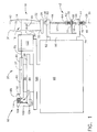
- Figure 1 is a side view of an airfoil coordinate measuring apparatus 10 for measuring a plurality of edge section coordinates (not shown) along an airfoil blade 12 at desired blade spanwise positions.
- Airfoil blade 12 has a blade chord line 14 extending through a cross section 16 of airfoil blade 12 being measured and includes a blade root (not shown) for mounting airfoil blade 12 to apparatus 10.
- Cross section 16 and chord line 14 are described in more detail below.
- Apparatus 10 further includes a blade engagement apparatus 18 and a measuring apparatus 20.
- Blade engagement apparatus 18 includes a mounting fixture 22 and a rotation shaft 24 including a first end 26 and a second end 28.
- Rotation shaft 24 has an axis of symmetry 30 which is substantially perpendicular to blade cross section 16 and substantially parallel to Earth's gravitational field (not shown) to minimize the tendency of shaft 24 to rotate due to the eccentric load of blade 12 and mounting fixture 22.
- Blade mounting fixture 22 engages the blade root of airfoil blade 12 and secures airfoil blade 12 to apparatus 10.
- Blade mounting fixture 22 secures blade 12 such that a line 32 extending from a blade root edge 33 to a blade tip edge 34 is substantially parallel to axis of symmetry 30.
- Line 32 is spaced a distance 35 from axis of symmetry 30.
- Distance 35 is substantially equal to a length of a longest chord line (not shown) of airfoil blade 12.
- An airfoil blade edge 36 extends from the airfoil blade root to blade tip edge 34.
- a plane (not shown in Fig. 1 ) substantially includes line 32 and axis of symmetry 30 and is substantially tangent to a mean line (not shown) of blade cross section 16 at blade edge 36.
- Rotation shaft 24 passes through a bearing retainer collar 38, an angular contact ball bearing 40, a friction assembly 42, an angular contact ball bearing 44, a bearing pre-load spring 46, an adjustment collar 48, and terminates at second end 28.
- Bearing retainer collar 38 includes a set screw (not shown) which fixedly attaches bearing retainer collar 38 to rotation shaft 24. Collar 38 presses against an inner race (not shown) of bearing 40.
- Bearing pre-load spring 46 presses against an inner race (not shown) of angular contact ball bearing 44 and against adjustment collar 48.
- a set screw (not shown) in adjustment collar 48 allows collar 48 to be repositioned and reattached to rotation shaft 24 thereby allowing an adjustment of a spring force exerted by bearing pre-load spring 46. Adjustments of the spring force exerted by bearing pre-load spring 46 prevent axial and radial shifts of rotation shaft 24.
- Blade elevation slide 50 includes arms 52 and 54 which include openings 56 and 58, respectively.
- Rotation shaft 24 extends through openings 56 and 58 and is supported by bearings 40 and 44.
- Outer races (not shown) of bearings 40 and 44 are mounted in openings 56 and 58.
- Blade elevation slide 50 is slidably mounted to a vibration dampening structure 60 which supports slide 50.
- Rotation shaft 24 passes through friction assembly 42 which includes a spring 62, a pair of collars 64 and 66, a friction washer 68, a thrust bearing 70, and a friction plate 72.
- Friction plate 72 is a thin flexible metal plate mounted to elevation slide 50 perpendicularly to axis of symmetry 30.
- Collar 66 is circumferentially positioned around rotation shaft 24 such that friction washer 68 makes contact with both friction plate 72 and collar 66.
- Collar 64 is positioned circumferentially around rotation shaft 24 to compress spring 62 against ball thrust bearing 70.
- Ball thrust bearing 70 presses against friction plate 72 and prevents undesired rotational friction between spring 62 and friction plate 72.
- a set screw (not shown) in collar 64 allows collar 64 to be repositioned and reattached to rotation shaft 24 thereby adjusting a compression of spring 62 and controlling the amount of rotational friction applied to rotation shaft 24 by friction plate 72.
- Blade elevation slide 50 is motorized to travel in a direction substantially parallel to axis of symmetry 30. Blade elevation slide 50 is controlled by a computer (not shown) which elevates airfoil blade 12 in a direction substantially parallel to axis of symmetry 30 for a measurement to be taken.
- Measuring apparatus 20 includes a first alignment slide 82 and a second alignment slide 84.
- First alignment slide 82 includes a first end 86, a second end 88, and axis of symmetry 37 which is substantially perpendicular to axis of symmetry 30 and which passes through first end 86 and second end 88.
- First alignment slide 82 also includes a blade edge alignment tool 92 mounted in close proximity to first end 86 and including a "V" shaped notch 94 (shown in Figure 2 ) which extends towards airfoil blade 12. Notch 94 engages airfoil blade 12 and rotates airfoil blade 12 properly for measuring.
- First alignment slide 82 is slidably mounted to a slide bearing 96 which is free moving, as described below, in a direction parallel to axis of symmetry 37.
- Second alignment slide 84 includes a first end 98 and a second end 100 and slidably supports slide bearing 96. Second alignment slide 84 is motorized to move in a direction substantially parallel to axis of symmetry 37 and is controlled by a computer (not shown). Second alignment slide 84 includes an arm 102 which extends from second alignment slide 84 perpendicularly to axis of symmetry 37.
- a limit switch assembly 104 includes an "OFF" mode and an “ON” mode and is positioned on apparatus 10 in close proximity to first alignment slide second end 88 and second alignment slide second end 100.
- Limit switch assembly 104 includes a switch 106 and an adjustable switch actuator 110.
- Switch 106 is mounted on arm 102 and extends into a gap 112 between first alignment slide 82 and arm 102.
- Switch actuator 110 is mounted on first alignment slide second end 88.
- Limit switch assembly 104 also includes a force spring 114 which spans gap 112 between arm 102 and first alignment slide 82. Spring 114 is biased to maintain switch assembly 104 in an "OFF" mode, as shown in Figure 1 .
- Switch actuator 110 is adjusted to engage switch 106 when force spring 114 is compressed causing limit switch assembly 104 to be in an "ON” mode. Adjustment of switch actuator 110 changes the amount of force necessary from spring 114 to cause switch assembly 104 to switch from the "OFF" mode to the "ON” mode.
- Apparatus 10 also includes motorized measurement slide 120, which is slidably mounted to vibration dampening structure 60, and second alignment slide 84, which is motorized and slidably mounted to measurement slide 120. Both measurement slide 120 and second alignment slide 84 are controlled by the computer which controls movement in a direction substantially parallel to axis of symmetry 37.
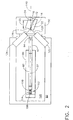
- FIG. 2 is a plan view of airfoil coordinate measuring apparatus 10.
- a pair of laser displacement sensors 122 and 124 are mounted to measurement slide 120.
- Each laser displacement sensor 122 and 124 is mounted to emit a laser energy signal 126 and 128 towards airfoil blade 12 at an angle of about 45 degrees relative to axis of symmetry 37.
- Each laser displacement sensor 122 and 124 is also mounted such that the center of each measuring range of laser displacement sensors 122 and 124 is located substantially at the same position on axis of symmetry 37.
- Laser displacement sensors 122 and 124 cannot be operated simultaneously as reflected laser energy from one laser sensor will disrupt the other laser sensor.
- Laser displacement sensor 122 deactivates when laser sensor 124 is emitting and performing measurements.
- Laser displacement sensor 124 operates similarly.
- Laser displacement sensors 122 and 124 continuously output a voltage that is linearly proportional to the distance to the nearest object in its beam path. The computer measures this voltage and converts the voltage to a distance.
- a plane 140 substantially includes axis of symmetry 30 (shown in Fig. 1 ) and is substantially tangent to a mean line (not shown) of blade cross section 16 at blade edge 36. Positioning rotation shaft 24 at distance 35 in plane 140 allows cross section 16 at blade edge 36 to be positioned substantially symmetrical with respect to axis of symmetry 37 when blade edge 36 is positioned for measurement.
- laser sensor 122 and laser sensor 124 are mounted so that laser energy signal 126 and laser energy signal 128 are directed .. toward airfoil blade 12 at an angle of greater than 45 degrees relative to axis of symmetry 37.
- a blade engagement tool (not shown) is used to rotate airfoil blade 12 such that blade chord line 14 is substantially parallel to axis of symmetry 37. This embodiment allows measurement of an entire cross section of airfoil blade 12 but does not permit detailed measurement of the airfoil blade edge (not shown in Fig. 2 ).
- blade 12 is inserted in blade mounting fixture 22.
- Blade mounting fixture 22 is manually rotated so that the airfoil blade edge at the desired blade spanwise section to be measured is near axis of symmetry 37.
- Measurement slide 120 is initially positioned by the computer such that the intersection of emitted laser beams 126 and 128 of laser displacement sensors 122 and 124, respectively, occurs in close proximity to the airfoil blade edge (not shown in Fig. 2 ).
- the computer drives second alignment slide 84 toward airfoil blade 12.
- force spring 114 causes first alignment slide 82 to move in a direction substantially parallel to second alignment slide 84.
- Blade edge alignment tool 92 is mounted to first end 86 of first alignment slide 82 and includes "V" shaped notch 94.
- second alignment slide 84 The computer controlled movement of second alignment slide 84 toward blade 12 causes first alignment slide 82 and notch 94 to be driven toward blade 12. Notch 94 captures the blade edge of airfoil blade 12. As first alignment slide 82 is forced towards blade 12, the edge of blade 12 is moved towards line of symmetry 37 causing rotation shaft 24 to rotate, overcoming the restraining torque of friction assembly 42. When notch 94 bottoms out on the airfoil blade edge of airfoil blade 12, force spring 114 is compressed and switch actuator 110 contacts switch 106 causing limit switch assembly 104 to be in the "ON" mode. The "ON" mode of limit switch assembly 104 is sensed by the computer, and the computer stops movement of second alignment slide 84. The computer retracts second alignment slide 84 which causes first alignment slide 82 and attached alignment tool 92 to retract via force spring 114. Airfoil blade 12 is now properly positioned for measurement of the edge section coordinates.
- the computer activates laser displacement sensor 122 and the computer drives measurement slide 120 towards blade 12 in a direction substantially parallel to axis of symmetry 37.
- laser displacement sensor 122 emits laser energy signal 126 towards airfoil blade 12, and receives a reflected signal (not shown) from airfoil blade 12.
- the output voltage of sensor 122 and position of slide 120 are repeatedly recorded by the computer as slide 120 is driven towards airfoil blade 12.
- the computer then deactivates laser sensor 122 and activates laser sensor 124.
- the computer then reverses the direction of movement of measurement slide 120 and retracts slide 120 while repeatedly recording position of measurement slide 120 and output voltage of sensor 124 as it emits laser energy signal 128 towards airfoil blade 12, and receives a reflected signal from airfoil blade 12.
- the computer calculates the section edge coordinates from the recorded information and the known geometry of the measurement system.
- the computer drives blade elevation slide 50 to move airfoil blade 12 in a direction substantially parallel to axis of symmetry 30 so that the edge section coordinates of the next section of airfoil blade 12 can be measured.
- the above described measuring apparatus for measuring airfoil blades is cost-effective and highly accurate.
- the apparatus includes a blade engagement tool which, in combination with a set of alignment slides, automatically and reliably positions the airfoil blade being measured.
- the apparatus uses positioning equipment that is inexpensive and reliable when compared to other airfoil blade measuring equipment currently in use. As such, a cost effective and accurate airfoil measuring apparatus is provided.
Description
- This invention relates generally to airfoil blades and, more particularly, to measuring airfoil blade coordinates.
- Airfoil blade edge shapes are critical in turbomachinery which operates at high revolutions per minute, or under high pressure or high temperature conditions. High performance of the airfoil blades enhances the turbomachine efficiency. Accurately determining the dimensions, locations, and attitudes of airfoil blade edges and surfaces facilitates enhancing blade performance.
- Airfoil blade measuring systems typically include an airfoil blade positioning apparatus and a separate measuring system. Digital cameras, modified microscopes, or coordinate measuring machines are used to measure blade dimensions, locations, and attitudes. Such cameras, microscopes, and measuring machines do not provide the desired accuracy and reliability, and are expensive, bulky, and slow to produce results. One such measuring apparatus is shown in
USA-4, 908,782 . - According to a first aspect of the invention, there is provided a method for measuring airfoil blade section coordinates with an apparatus, the apparatus including a blade engagement system including a blade elevation slide, a blade mounting fixture, and a rotation shaft connected to the blade elevation slide and to the blade mounting fixture, and a measuring system including a blade alignment tool, a first alignment slide having an axis of symmetry, a second alignment slide in slidable contact with the first alignment slide, a measurement slide in slidable contact with the second alignment slide, and a plurality of laser displacement sensors positioned on the measurement slide to measure the airfoil blade section coordinates, said method being characterised by the steps of securing an airfoil blade to the blade engagement system; engaging and aligning the airfoil blade edge using the blade edge alignment tool; and using the measuring system to automatically measure the airfoil blade.
- The method may further comprise the step of mounting the blade engagement system and the measuring system to a vibration dampening structure.
- The blade elevation slide may have a first direction of travel and the second alignment slide may have a second direction of travel and an axis of symmetry generally parallel to the second direction of travel. The method may further comprise the step of controlling the first direction of travel of the blade elevation slide, the second direction of travel of the second alignment slide, and second direction of travel of the measurement slide with a computer.
- The plurality of displacement sensors may be configured to receive and emit laser energy signals so that the emitted laser energy signals intersect at the airfoil blade and the method may further comprise the step of mounting the plurality of laser displacement sensors at about 45 degrees relative to the first alignment slide axis of symmetry.
- The airfoil blade may have an airfoil blade edge and the method may further comprise the step of rotating the airfoil blade edge with the blade edge alignment tool such that the airfoil blade edge is substantially symmetrical with respect to the first alignment slide axis of symmetry.
- The measuring system may include a limit switch assembly including a switch attached to the second alignment slide, a limit switch actuator attached to the first alignment slide, and a force spring attached between the first alignment slide and the second alignment slide and the method may further comprise the step of adjusting the limit switch actuator to activate the switch when the blade alignment tool has bottomed out on the airfoil blade.
- The blade engagement system may further include a friction assembly which prevents unrestrained rotation of the rotation shaft and the method may further comprise the step of adjusting the friction assembly to permit the rotation shaft to be rotated by the blade edge alignment tool and the rotation shaft position to remain stationary when the blade edge alignment tool is retracted.
- The airfoil blade may include a blade chord line which extends through each section of the airfoil blade being measured including a leading edge and the method may further comprise the step of rotating the airfoil blade edge with the blade edge alignment tool such that the blade chord line at the leading edge of the airfoil blade being measured is coincident with the axis of symmetry of the first alignment slide.
- The first alignment slide may have an axis of symmetry generally parallel to the second direction of travel and the method may further comprise the step of mounting the laser displacement sensors to the apparatus at greater than 45 degrees relative to the first alignment slide axis of symmetry.
- According to a second aspect of the invention, there is provided an apparatus for measuring airfoil blade section coordinates of an airfoil blade having an airfoil blade edge said apparatus comprising a blade engagement apparatus configured to receive the airfoil blade, said blade engagement apparatus comprising a blade elevation slide having a first direction of travel, a blade mounting fixture, and a rotation shaft connected to said blade elevation slide and to said blade mounting fixture; and a measuring apparatus configured to measure the airfoil blade section coordinates, said measuring apparatus comprising a first alignment slide having a second direction of travel, and a plurality of laser displacement sensors positioned to measure the airfoil blade, said first alignment slide comprising an axis of symmetry; characterised in that said measuring apparatus comprises a blade edge alignment tool configured to align the airfoil blade edge and mounted to said alignment slide.
- The measuring apparatus may further comprise a second alignment slide for positioning the first alignment slide, the second alignment slide in slidable contact with the first alignment slide.
- The measuring apparatus may further comprise a measurement slide, the sensors being mounted on the measurement slide, the measurement slide in slidable contact with the second alignment slide.
- The plurality of laser displacement sensors may be configured to receive and emit laser energy signals, the plurality of laser displacement sensors comprising two laser displacement sensors, the emitted laser energy signals from the two displacement sensors intersecting at a common point on the axis of symmetry of the first alignment slide.
- The laser displacement sensors may further comprise a measuring range, the emitted laser energy signals from the two displacement sensors intersect at a center of the measuring range of each displacement sensor.
- The first alignment slide may have an axis of symmetry generally parallel to the second direction of travel, the laser displacement sensors being mounted to the measurement slide at about 45 degrees relative to the first alignment slide axis of symmetry.
- The measuring apparatus may further comprise a limit stop switch assembly for monitoring movement of the first alignment slide relative to the second alignment slide, the limit stop switch assembly comprising a first switch mounted on the second alignment slide, an adjustable limit switch actuator mounted on the first alignment slide, and a force spring attached between the first alignment slide and the second alignment slide.
- The apparatus may further comprise a vibration dampening structure supporting the measuring apparatus and the blade engagement apparatus, and a computer configured to control the second direction of travel of the second alignment slide, the second direction of travel of the measurement slide, and the first direction of travel of the blade elevation slide.
- The rotation shaft may be configured to rotate such that an airfoil blade cross section at the blade edge being measured is substantially symmetrical with respect to the first alignment slide axis of symmetry, the rotation shaft having an axis of symmetry generally parallel to the first direction of travel.
- The first alignment slide may have an axis of symmetry generally parallel to the second direction of travel, the laser displacement sensors being mounted to the measurement slide at greater than 45 degrees relative to the first alignment slide axis of symmetry.
- The airfoil blade may have a blade chord line extending through each section of the airfoil blade being measured, the rotation shaft configured to rotate the airfoil blade edge such that a portion of the blade chord line is substantially coincident with the intersection between the emitted laser energy signals.
- In an exemplary embodiment, an airfoil measuring system includes two movable alignment slides, and one moveable measurement slide, which are controlled by the computer, and a pair of laser displacement sensors of appropriate range, resolution and accuracy, which receive and emit laser energy signals. A blade engagement tool is mounted to one of the alignment slides and includes a notch which engages and aligns the airfoil blade edge to be measured. The movement of the first and second alignment slides is controlled by a limit switch assembly which, when engaged, causes the two alignment slides to retract after the airfoil blade has been properly aligned.
- In operation, the measurement slide moves the laser displacement sensors while the sensors are measuring the edge coordinates and transmitting the measurements back to the computer. The measurements are then repeated at several spanwise elevations along the blade edge. As a result, the airfoil measuring apparatus eliminates more costly and more complicated known blade positioning equipment and provides a system that is highly accurate, reliable, and cost-effective.
- The invention will now be described in greater detail, by way of example, with reference to the drawings, in which:-
-
Figure 1 is a schematic side view of an airfoil coordinate measuring apparatus; and -
Figure 2 is a schematic plan view of the airfoil coordinate measuring apparatus shown inFigure 1 . -
Figure 1 is a side view of an airfoilcoordinate measuring apparatus 10 for measuring a plurality of edge section coordinates (not shown) along anairfoil blade 12 at desired blade spanwise positions.Airfoil blade 12 has ablade chord line 14 extending through across section 16 ofairfoil blade 12 being measured and includes a blade root (not shown) for mountingairfoil blade 12 toapparatus 10.Cross section 16 andchord line 14 are described in more detail below. -
Apparatus 10 further includes ablade engagement apparatus 18 and ameasuring apparatus 20.Blade engagement apparatus 18 includes amounting fixture 22 and arotation shaft 24 including afirst end 26 and asecond end 28.Rotation shaft 24 has an axis ofsymmetry 30 which is substantially perpendicular toblade cross section 16 and substantially parallel to Earth's gravitational field (not shown) to minimize the tendency ofshaft 24 to rotate due to the eccentric load ofblade 12 and mountingfixture 22.Blade mounting fixture 22 engages the blade root ofairfoil blade 12 and securesairfoil blade 12 toapparatus 10. -
Blade mounting fixture 22 securesblade 12 such that aline 32 extending from ablade root edge 33 to ablade tip edge 34 is substantially parallel to axis ofsymmetry 30.Line 32 is spaced adistance 35 from axis ofsymmetry 30.Distance 35 is substantially equal to a length of a longest chord line (not shown) ofairfoil blade 12. Anairfoil blade edge 36 extends from the airfoil blade root toblade tip edge 34. A plane (not shown inFig. 1 ) substantially includesline 32 and axis ofsymmetry 30 and is substantially tangent to a mean line (not shown) ofblade cross section 16 atblade edge 36.Positioning rotation shaft 24 atdistance 35 in the aforementioned plane allowsblade edge 36 atcross section 16 to be positioned substantially symmetrical with respect to a second axis of symmetry 37 (described in detail below) whenblade edge 36 is positioned for measurement. Mountingfixture 22 is fixedly mounted toend 26 ofrotation shaft 24.Rotation shaft 24 passes through abearing retainer collar 38, an angular contact ball bearing 40, afriction assembly 42, an angular contact ball bearing 44, a bearing pre-loadspring 46, anadjustment collar 48, and terminates atsecond end 28.Bearing retainer collar 38 includes a set screw (not shown) which fixedly attaches bearingretainer collar 38 torotation shaft 24.Collar 38 presses against an inner race (not shown) of bearing 40. Bearing pre-loadspring 46 presses against an inner race (not shown) of angular contact ball bearing 44 and againstadjustment collar 48. A set screw (not shown) inadjustment collar 48 allowscollar 48 to be repositioned and reattached torotation shaft 24 thereby allowing an adjustment of a spring force exerted by bearing pre-loadspring 46. Adjustments of the spring force exerted by bearing pre-loadspring 46 prevent axial and radial shifts ofrotation shaft 24. -
Blade elevation slide 50 includesarms openings Rotation shaft 24 extends throughopenings bearings bearings openings Blade elevation slide 50 is slidably mounted to avibration dampening structure 60 which supportsslide 50. -
Rotation shaft 24 passes throughfriction assembly 42 which includes aspring 62, a pair ofcollars friction washer 68, a thrust bearing 70, and afriction plate 72.Friction plate 72 is a thin flexible metal plate mounted toelevation slide 50 perpendicularly to axis ofsymmetry 30. Collar 66 is circumferentially positioned aroundrotation shaft 24 such thatfriction washer 68 makes contact with bothfriction plate 72 andcollar 66.Collar 64 is positioned circumferentially aroundrotation shaft 24 to compressspring 62 against ball thrustbearing 70. Ball thrust bearing 70 presses againstfriction plate 72 and prevents undesired rotational friction betweenspring 62 andfriction plate 72. A set screw (not shown) incollar 64 allowscollar 64 to be repositioned and reattached torotation shaft 24 thereby adjusting a compression ofspring 62 and controlling the amount of rotational friction applied torotation shaft 24 byfriction plate 72. -
Blade elevation slide 50 is motorized to travel in a direction substantially parallel to axis ofsymmetry 30.Blade elevation slide 50 is controlled by a computer (not shown) which elevatesairfoil blade 12 in a direction substantially parallel to axis ofsymmetry 30 for a measurement to be taken. - Measuring
apparatus 20 includes afirst alignment slide 82 and asecond alignment slide 84.First alignment slide 82 includes afirst end 86, asecond end 88, and axis ofsymmetry 37 which is substantially perpendicular to axis ofsymmetry 30 and which passes throughfirst end 86 andsecond end 88.First alignment slide 82 also includes a bladeedge alignment tool 92 mounted in close proximity tofirst end 86 and including a "V" shaped notch 94 (shown inFigure 2 ) which extends towardsairfoil blade 12.Notch 94 engagesairfoil blade 12 and rotatesairfoil blade 12 properly for measuring.First alignment slide 82 is slidably mounted to aslide bearing 96 which is free moving, as described below, in a direction parallel to axis ofsymmetry 37. -
Second alignment slide 84 includes afirst end 98 and asecond end 100 and slidably supports slidebearing 96.Second alignment slide 84 is motorized to move in a direction substantially parallel to axis ofsymmetry 37 and is controlled by a computer (not shown).Second alignment slide 84 includes anarm 102 which extends fromsecond alignment slide 84 perpendicularly to axis ofsymmetry 37. - A
limit switch assembly 104 includes an "OFF" mode and an "ON" mode and is positioned onapparatus 10 in close proximity to first alignment slidesecond end 88 and second alignment slidesecond end 100.Limit switch assembly 104 includes aswitch 106 and anadjustable switch actuator 110.Switch 106 is mounted onarm 102 and extends into agap 112 betweenfirst alignment slide 82 andarm 102.Switch actuator 110 is mounted on first alignment slidesecond end 88.Limit switch assembly 104 also includes aforce spring 114 which spansgap 112 betweenarm 102 andfirst alignment slide 82.Spring 114 is biased to maintainswitch assembly 104 in an "OFF" mode, as shown inFigure 1 .Switch actuator 110 is adjusted to engageswitch 106 whenforce spring 114 is compressed causinglimit switch assembly 104 to be in an "ON" mode. Adjustment ofswitch actuator 110 changes the amount of force necessary fromspring 114 to causeswitch assembly 104 to switch from the "OFF" mode to the "ON" mode. -
Apparatus 10 also includesmotorized measurement slide 120, which is slidably mounted tovibration dampening structure 60, andsecond alignment slide 84, which is motorized and slidably mounted tomeasurement slide 120. Bothmeasurement slide 120 andsecond alignment slide 84 are controlled by the computer which controls movement in a direction substantially parallel to axis ofsymmetry 37. -
Figure 2 is a plan view of airfoil coordinate measuringapparatus 10. A pair oflaser displacement sensors measurement slide 120. Eachlaser displacement sensor laser energy signal airfoil blade 12 at an angle of about 45 degrees relative to axis ofsymmetry 37. Eachlaser displacement sensor laser displacement sensors symmetry 37.Laser displacement sensors Laser displacement sensor 122 deactivates whenlaser sensor 124 is emitting and performing measurements.Laser displacement sensor 124 operates similarly.Laser displacement sensors - A
plane 140 substantially includes axis of symmetry 30 (shown inFig. 1 ) and is substantially tangent to a mean line (not shown) ofblade cross section 16 atblade edge 36.Positioning rotation shaft 24 atdistance 35 inplane 140 allowscross section 16 atblade edge 36 to be positioned substantially symmetrical with respect to axis ofsymmetry 37 whenblade edge 36 is positioned for measurement. - In another embodiment,
laser sensor 122 andlaser sensor 124 are mounted so thatlaser energy signal 126 andlaser energy signal 128 are directed .. towardairfoil blade 12 at an angle of greater than 45 degrees relative to axis ofsymmetry 37. In this embodiment, a blade engagement tool (not shown) is used to rotateairfoil blade 12 such thatblade chord line 14 is substantially parallel to axis ofsymmetry 37. This embodiment allows measurement of an entire cross section ofairfoil blade 12 but does not permit detailed measurement of the airfoil blade edge (not shown inFig. 2 ). - In operation,
blade 12 is inserted inblade mounting fixture 22.Blade mounting fixture 22 is manually rotated so that the airfoil blade edge at the desired blade spanwise section to be measured is near axis ofsymmetry 37.Measurement slide 120 is initially positioned by the computer such that the intersection of emittedlaser beams laser displacement sensors Fig. 2 ). The computer drivessecond alignment slide 84 towardairfoil blade 12. Assecond alignment slide 84 is moving,force spring 114 causesfirst alignment slide 82 to move in a direction substantially parallel tosecond alignment slide 84. Bladeedge alignment tool 92 is mounted tofirst end 86 offirst alignment slide 82 and includes "V" shapednotch 94. The computer controlled movement ofsecond alignment slide 84 towardblade 12 causesfirst alignment slide 82 and notch 94 to be driven towardblade 12.Notch 94 captures the blade edge ofairfoil blade 12. Asfirst alignment slide 82 is forced towardsblade 12, the edge ofblade 12 is moved towards line ofsymmetry 37 causingrotation shaft 24 to rotate, overcoming the restraining torque offriction assembly 42. Whennotch 94 bottoms out on the airfoil blade edge ofairfoil blade 12,force spring 114 is compressed andswitch actuator 110 contacts switch 106 causinglimit switch assembly 104 to be in the "ON" mode. The "ON" mode oflimit switch assembly 104 is sensed by the computer, and the computer stops movement ofsecond alignment slide 84. The computer retractssecond alignment slide 84 which causesfirst alignment slide 82 and attachedalignment tool 92 to retract viaforce spring 114.Airfoil blade 12 is now properly positioned for measurement of the edge section coordinates. - After
second alignment slide 84 is retracted, the computer activateslaser displacement sensor 122 and the computer drivesmeasurement slide 120 towardsblade 12 in a direction substantially parallel to axis ofsymmetry 37. Asmeasurement slide 120 is driven towardsairfoil blade 12,laser displacement sensor 122 emitslaser energy signal 126 towardsairfoil blade 12, and receives a reflected signal (not shown) fromairfoil blade 12. The output voltage ofsensor 122 and position ofslide 120 are repeatedly recorded by the computer asslide 120 is driven towardsairfoil blade 12. - Once
measurement slide 120 has traveled a desired distance, the computer then deactivateslaser sensor 122 and activateslaser sensor 124. The computer then reverses the direction of movement ofmeasurement slide 120 and retracts slide 120 while repeatedly recording position ofmeasurement slide 120 and output voltage ofsensor 124 as it emitslaser energy signal 128 towardsairfoil blade 12, and receives a reflected signal fromairfoil blade 12. Aftermeasurement slide 120 has returned to its starting position, the computer then calculates the section edge coordinates from the recorded information and the known geometry of the measurement system. - The computer drives
blade elevation slide 50 to moveairfoil blade 12 in a direction substantially parallel to axis ofsymmetry 30 so that the edge section coordinates of the next section ofairfoil blade 12 can be measured. - This elevating and measurement process is repeated until the edge section coordinates at the desired spanwise locations are recorded, and then the computer retracts
blade elevation slide 50 to an original position so thatairfoil blade 12 can be removed fromapparatus 10. - The above described measuring apparatus for measuring airfoil blades is cost-effective and highly accurate. The apparatus includes a blade engagement tool which, in combination with a set of alignment slides, automatically and reliably positions the airfoil blade being measured. Furthermore, the apparatus uses positioning equipment that is inexpensive and reliable when compared to other airfoil blade measuring equipment currently in use. As such, a cost effective and accurate airfoil measuring apparatus is provided.
Claims (10)
- A method for measuring airfoil blade section coordinates with an apparatus (10), the apparatus including a blade engagement system (18) including a blade elevation slide (50), a blade mounting fixture (22), and a rotation shaft (24) connected to the blade elevation slide and to the blade mounting fixture, and a measuring system (20) including a blade alignment tool (92), a first alignment slide (82) having an axis of symmetry (37), a second alignment slide (84) in slidable contact with the first alignment slide, a measurement slide (120) in slidable contact with the second alignment slide, and a plurality of laser displacement sensors (122, 124) positioned on the measurement slide to measure the airfoil blade section coordinates, said method being characterised by the steps of:securing an airfoil blade (12) to the blade engagement system (18);engaging and aligning the airfoil blade edge (36) using the blade edge alignment tool (92); andusing the measuring system (20) to automatically measure the airfoil blade (12).
- A method in accordance with Claim 1, further comprising the step of mounting the blade engagement system (18) and the measuring system (20) to a vibration dampening structure (60).
- A method in accordance with Claim 1 or 2, wherein the blade elevation slide (50) has a first direction of travel and the second alignment slide (84) has a second direction of travel and an axis of symmetry (37) generally parallel to the second direction of travel, said method further comprising the step of controlling the first direction of travel of the blade elevation slide, the second direction of travel of the second alignment slide, and second direction of travel of the measurement slide (120) with a computer.
- A method in accordance with Claim 1, 2 or 3, wherein the plurality of displacement sensors (122, 124) are configured to receive and emit laser energy signals (126, 128) so that the emitted laser energy signals intersect at the airfoil blade (12), said method further comprising the step of mounting the plurality of laser displacement sensors at about 45 degrees relative to the first alignment slide axis of symmetry (37).
- A method in accordance with any preceding claim, wherein the airfoil blade (12) has an airfoil blade edge (36), said method further comprising the step of rotating the airfoil blade edge with the blade edge alignment tool (92) such that the airfoil blade edge is substantially symmetrical with respect to the first alignment slide axis of symmetry (37).
- Apparatus (10) for measuring airfoil blade section coordinates of an airfoil blade (12) having an airfoil blade edge (36), said apparatus comprising:a blade engagement apparatus (18) configured to receive the airfoil blade (12), said blade engagement apparatus (18) comprising a blade elevation slide (50) having a first direction of travel, a blade mounting fixture (22), and a rotation shaft (24) connected to said blade elevation slide (50) and to said blade mounting fixture (22); anda measuring apparatus (20) configured to measure the airfoil blade section coordinates, said measuring apparatus (20) comprising a first alignment slide (82) having a second direction of travel, and a plurality of laser displacement sensors (122, 124) positioned to measure the airfoil blade, said first alignment slide comprising an axis of symmetry (37);characterised in that said measuring apparatus (20) comprises a blade edge alignment tool (92) configured to align the airfoil blade edge (36) and mounted to said alignment slide (82).
- Apparatus (10) in accordance with Claim 6, wherein said measuring apparatus (20) further comprises a second alignment slide (84) for positioning said first alignment slide (82), said second alignment slide being in slidable contact with said first alignment slide.
- Apparatus (10) in accordance with Claim 7, wherein said measuring apparatus (20) further comprises a measurement slide (120), said sensors (122, 124) mounted on said measurement slide, said measurement slide in slidable contact with said second alignment slide (84).
- Apparatus (10) in accordance with any one of Claim 6 to 8, wherein said plurality of laser displacement sensors (122, 124) are configured to receive and emit laser energy signals (126, 128), said plurality of laser displacement sensors comprising two laser displacement sensors, said emitted laser energy signals from said two displacement sensors intersect at a common point on said axis of symmetry (37) of said first alignment slide (82).
- Apparatus (10) in accordance with Claim 9, wherein said laser displacement sensors (122, 124) further comprise a measuring range, said emitted laser energy signals (126, 128) from said two displacement sensors intersect at a center of said measuring range of each displacement sensor.
Applications Claiming Priority (2)
| Application Number | Priority Date | Filing Date | Title |
|---|---|---|---|
| US375108 | 1999-08-16 | ||
| US09/375,108 US6209216B1 (en) | 1999-08-16 | 1999-08-16 | Methods and apparatus for measuring airfoil coordinates |
Publications (3)
| Publication Number | Publication Date |
|---|---|
| EP1077361A2 EP1077361A2 (en) | 2001-02-21 |
| EP1077361A3 EP1077361A3 (en) | 2004-02-04 |
| EP1077361B1 true EP1077361B1 (en) | 2011-10-12 |
Family
ID=23479529
Family Applications (1)
| Application Number | Title | Priority Date | Filing Date |
|---|---|---|---|
| EP00306656A Expired - Lifetime EP1077361B1 (en) | 1999-08-16 | 2000-08-04 | Method and apparatus for measuring airfoil coordinates |
Country Status (3)
| Country | Link |
|---|---|
| US (1) | US6209216B1 (en) |
| EP (1) | EP1077361B1 (en) |
| JP (1) | JP5036931B2 (en) |
Families Citing this family (12)
| Publication number | Priority date | Publication date | Assignee | Title |
|---|---|---|---|---|
| US6449044B1 (en) | 2001-08-06 | 2002-09-10 | General Motors Corporation | Method for checking cam lobe angles |
| US6792655B2 (en) | 2001-11-09 | 2004-09-21 | General Electric Company | Apparatus for correcting airfoil twist |
| US20080134505A1 (en) * | 2006-12-12 | 2008-06-12 | Thomas Andrew Gabriel | Method and fixture for manufacturing components |
| SG155788A1 (en) * | 2008-03-18 | 2009-10-29 | Turbine Overhaul Services Pte | Methods and apparatuses for correcting twist angle in a gas turbine engine blade |
| US8122601B2 (en) * | 2008-04-15 | 2012-02-28 | United Technologies Corporation | Methods for correcting twist angle in a gas turbine engine blade |
| US8127581B2 (en) * | 2008-04-15 | 2012-03-06 | United Technologies Corporation | Turbine blade twist angle correction tooling |
| US7970555B2 (en) * | 2008-04-15 | 2011-06-28 | United Technologies Corporation | Method for developing a repair process to correct a deformed gas turbine engine component |
| CN102147221A (en) * | 2010-11-20 | 2011-08-10 | 无锡透平叶片有限公司 | Three-coordinate measuring method of blade with T-shaped root |
| CN102141389A (en) * | 2010-11-22 | 2011-08-03 | 无锡透平叶片有限公司 | Three-coordinate measuring method of tenon tooth blade |
| EP2998063B1 (en) * | 2014-09-16 | 2019-03-13 | Ansaldo Energia Switzerland AG | Tool for measuring geometrical parameters of a blade or vane in a turbomachine |
| CN108759682A (en) * | 2018-05-02 | 2018-11-06 | 珠海保税区摩天宇航空发动机维修有限公司 | A kind of aeroengine fan blades chord width optics intelligent measure equipment |
| CN112964197B (en) * | 2021-03-23 | 2022-04-29 | 哈尔滨工业大学 | Micro-sphere surface morphology detection device based on negative feedback phase-locked vibration suppression |
Family Cites Families (12)
| Publication number | Priority date | Publication date | Assignee | Title |
|---|---|---|---|---|
| US2977533A (en) * | 1957-11-07 | 1961-03-28 | Sheffield Corp | Gaging device |
| US3101552A (en) * | 1958-08-07 | 1963-08-27 | Warner Swasey Co | Twist measuring apparatus |
| US4373804A (en) | 1979-04-30 | 1983-02-15 | Diffracto Ltd. | Method and apparatus for electro-optically determining the dimension, location and attitude of objects |
| US4908782A (en) * | 1983-05-19 | 1990-03-13 | Compressor Components Textron Inc. | Airfoil inspection method |
| JPS6186606A (en) | 1984-10-05 | 1986-05-02 | Hitachi Ltd | Configuration measuring method without contact |
| GB8508391D0 (en) | 1985-03-30 | 1985-05-09 | Ae Plc | Measurement of engineering components |
| US5162659A (en) | 1991-03-06 | 1992-11-10 | Northwest Airlines, Inc. | Method and apparatus for noncontact inspection of engine blades |
| US5152070A (en) * | 1991-09-09 | 1992-10-06 | Dresser Industries, Inc. | Position validator device |
| US5175601A (en) | 1991-10-15 | 1992-12-29 | Electro-Optical Information Systems | High-speed 3-D surface measurement surface inspection and reverse-CAD system |
| US5444536A (en) | 1992-04-28 | 1995-08-22 | Mtu Motoren- Und Turbinen-Union Muenchen Gmbh | Apparatus for measuring the curvature of a profile, such as an edge of a turbine blade |
| US5625958A (en) * | 1995-09-06 | 1997-05-06 | United Technologies Corporation | Method and a gauge for measuring the service life remaining in a blade |
| US5873566A (en) | 1997-04-17 | 1999-02-23 | International Business Machines Corporation | Locator actuation apparatus |
-
1999
- 1999-08-16 US US09/375,108 patent/US6209216B1/en not_active Expired - Lifetime
-
2000
- 2000-08-04 EP EP00306656A patent/EP1077361B1/en not_active Expired - Lifetime
- 2000-08-09 JP JP2000240530A patent/JP5036931B2/en not_active Expired - Fee Related
Also Published As
| Publication number | Publication date |
|---|---|
| EP1077361A2 (en) | 2001-02-21 |
| JP2001108430A (en) | 2001-04-20 |
| EP1077361A3 (en) | 2004-02-04 |
| US6209216B1 (en) | 2001-04-03 |
| JP5036931B2 (en) | 2012-09-26 |
Similar Documents
| Publication | Publication Date | Title |
|---|---|---|
| EP1077361B1 (en) | Method and apparatus for measuring airfoil coordinates | |
| CN100410625C (en) | Shedding profilogram measuring apparatus | |
| US7568373B2 (en) | Method of error compensation in a coordinate measuring machine | |
| US8100311B2 (en) | Friction stir welding head and method for controlling a friction stir welding head | |
| US4222172A (en) | Vane area measuring device | |
| US7294806B2 (en) | Method and device for measuring and adjusting the electrode for taper machining on an electrical discharge machine | |
| US6842995B2 (en) | Methods and apparatus for aligning components for inspection | |
| US5077908A (en) | Apparatus for measuring the roundness of a surface of an object | |
| US20090144999A1 (en) | Interior contour measurement probe | |
| KR20030020306A (en) | Method of determining the angle of a rotor blade of a wind power installation | |
| KR101829964B1 (en) | Method for measuring a rotor blade angle | |
| US8171770B2 (en) | Calibration tool for air data measurement devices | |
| JPH10505009A (en) | Method and apparatus for detecting and correcting seaming and wear errors during precision drilling | |
| DK2855930T3 (en) | A method for the installation of sensors in the rotor blades and the installation device | |
| CN108106547B (en) | Plane three-degree-of-freedom macro-micro composite positioning system and method based on laser sensor | |
| JP3037422B2 (en) | Multi-axis coordinate scanning measurement device | |
| US5099585A (en) | In-process machine gage | |
| EP1988359A2 (en) | Measurement device for measuring the parameters of a blade rotor and measurement process for measuring with said device | |
| US4665625A (en) | Component measuring apparatus with multiple component multiple positioning device | |
| US4597187A (en) | Compressor vane gage | |
| CN111121709B (en) | System and method for measuring thrust line of small-size large-expansion-ratio nozzle engine | |
| EP3450100A2 (en) | Grinding machine calibration | |
| US7107695B2 (en) | Device and process for profile measurement | |
| EP4227461A1 (en) | Measuring system of a feeder | |
| WO2009102266A1 (en) | Measurement arrangement with a measurement head in order to carry out inspection measurement |
Legal Events
| Date | Code | Title | Description |
|---|---|---|---|
| PUAI | Public reference made under article 153(3) epc to a published international application that has entered the european phase |
Free format text: ORIGINAL CODE: 0009012 |
|
| AK | Designated contracting states |
Kind code of ref document: A2 Designated state(s): AT BE CH CY DE DK ES FI FR GB GR IE IT LI LU MC NL PT SE |
|
| AX | Request for extension of the european patent |
Free format text: AL;LT;LV;MK;RO;SI |
|
| PUAL | Search report despatched |
Free format text: ORIGINAL CODE: 0009013 |
|
| AK | Designated contracting states |
Kind code of ref document: A3 Designated state(s): AT BE CH CY DE DK ES FI FR GB GR IE IT LI LU MC NL PT SE |
|
| AX | Request for extension of the european patent |
Extension state: AL LT LV MK RO SI |
|
| RIC1 | Information provided on ipc code assigned before grant |
Ipc: 7G 01B 11/24 A Ipc: 7B 23Q 17/24 B Ipc: 7G 01B 11/245 B |
|
| 17P | Request for examination filed |
Effective date: 20040804 |
|
| AKX | Designation fees paid |
Designated state(s): DE FR GB IT |
|
| 17Q | First examination report despatched |
Effective date: 20041112 |
|
| GRAP | Despatch of communication of intention to grant a patent |
Free format text: ORIGINAL CODE: EPIDOSNIGR1 |
|
| RTI1 | Title (correction) |
Free format text: METHOD AND APPARATUS FOR MEASURING AIRFOIL COORDINATES |
|
| GRAS | Grant fee paid |
Free format text: ORIGINAL CODE: EPIDOSNIGR3 |
|
| GRAA | (expected) grant |
Free format text: ORIGINAL CODE: 0009210 |
|
| AK | Designated contracting states |
Kind code of ref document: B1 Designated state(s): DE FR GB IT |
|
| REG | Reference to a national code |
Ref country code: GB Ref legal event code: FG4D |
|
| REG | Reference to a national code |
Ref country code: DE Ref legal event code: R096 Ref document number: 60046544 Country of ref document: DE Effective date: 20120105 |
|
| PLBE | No opposition filed within time limit |
Free format text: ORIGINAL CODE: 0009261 |
|
| STAA | Information on the status of an ep patent application or granted ep patent |
Free format text: STATUS: NO OPPOSITION FILED WITHIN TIME LIMIT |
|
| 26N | No opposition filed |
Effective date: 20120713 |
|
| REG | Reference to a national code |
Ref country code: DE Ref legal event code: R097 Ref document number: 60046544 Country of ref document: DE Effective date: 20120713 |
|
| REG | Reference to a national code |
Ref country code: FR Ref legal event code: PLFP Year of fee payment: 17 |
|
| PGFP | Annual fee paid to national office [announced via postgrant information from national office to epo] |
Ref country code: IT Payment date: 20160824 Year of fee payment: 17 Ref country code: DE Payment date: 20160826 Year of fee payment: 17 Ref country code: GB Payment date: 20160830 Year of fee payment: 17 |
|
| PGFP | Annual fee paid to national office [announced via postgrant information from national office to epo] |
Ref country code: FR Payment date: 20160825 Year of fee payment: 17 |
|
| REG | Reference to a national code |
Ref country code: DE Ref legal event code: R119 Ref document number: 60046544 Country of ref document: DE |
|
| GBPC | Gb: european patent ceased through non-payment of renewal fee |
Effective date: 20170804 |
|
| REG | Reference to a national code |
Ref country code: FR Ref legal event code: ST Effective date: 20180430 |
|
| PG25 | Lapsed in a contracting state [announced via postgrant information from national office to epo] |
Ref country code: DE Free format text: LAPSE BECAUSE OF NON-PAYMENT OF DUE FEES Effective date: 20180301 Ref country code: GB Free format text: LAPSE BECAUSE OF NON-PAYMENT OF DUE FEES Effective date: 20170804 |
|
| PG25 | Lapsed in a contracting state [announced via postgrant information from national office to epo] |
Ref country code: IT Free format text: LAPSE BECAUSE OF NON-PAYMENT OF DUE FEES Effective date: 20170804 Ref country code: FR Free format text: LAPSE BECAUSE OF NON-PAYMENT OF DUE FEES Effective date: 20170831 |