EP1077412A2 - Bus system having improved control process - Google Patents
Bus system having improved control process Download PDFInfo
- Publication number
- EP1077412A2 EP1077412A2 EP00202810A EP00202810A EP1077412A2 EP 1077412 A2 EP1077412 A2 EP 1077412A2 EP 00202810 A EP00202810 A EP 00202810A EP 00202810 A EP00202810 A EP 00202810A EP 1077412 A2 EP1077412 A2 EP 1077412A2
- Authority
- EP
- European Patent Office
- Prior art keywords
- bus
- devices
- controller
- data transfer
- satisfied
- Prior art date
- Legal status (The legal status is an assumption and is not a legal conclusion. Google has not performed a legal analysis and makes no representation as to the accuracy of the status listed.)
- Withdrawn
Links
Images

Classifications
-
- G—PHYSICS
- G06—COMPUTING; CALCULATING OR COUNTING
- G06F—ELECTRIC DIGITAL DATA PROCESSING
- G06F11/00—Error detection; Error correction; Monitoring
- G06F11/07—Responding to the occurrence of a fault, e.g. fault tolerance
- G06F11/0703—Error or fault processing not based on redundancy, i.e. by taking additional measures to deal with the error or fault not making use of redundancy in operation, in hardware, or in data representation
- G06F11/0706—Error or fault processing not based on redundancy, i.e. by taking additional measures to deal with the error or fault not making use of redundancy in operation, in hardware, or in data representation the processing taking place on a specific hardware platform or in a specific software environment
- G06F11/073—Error or fault processing not based on redundancy, i.e. by taking additional measures to deal with the error or fault not making use of redundancy in operation, in hardware, or in data representation the processing taking place on a specific hardware platform or in a specific software environment in a memory management context, e.g. virtual memory or cache management
-
- G—PHYSICS
- G06—COMPUTING; CALCULATING OR COUNTING
- G06F—ELECTRIC DIGITAL DATA PROCESSING
- G06F13/00—Interconnection of, or transfer of information or other signals between, memories, input/output devices or central processing units
- G06F13/38—Information transfer, e.g. on bus
- G06F13/42—Bus transfer protocol, e.g. handshake; Synchronisation
- G06F13/4204—Bus transfer protocol, e.g. handshake; Synchronisation on a parallel bus
- G06F13/4234—Bus transfer protocol, e.g. handshake; Synchronisation on a parallel bus being a memory bus
- G06F13/4243—Bus transfer protocol, e.g. handshake; Synchronisation on a parallel bus being a memory bus with synchronous protocol
-
- G—PHYSICS
- G06—COMPUTING; CALCULATING OR COUNTING
- G06F—ELECTRIC DIGITAL DATA PROCESSING
- G06F11/00—Error detection; Error correction; Monitoring
- G06F11/07—Responding to the occurrence of a fault, e.g. fault tolerance
- G06F11/0703—Error or fault processing not based on redundancy, i.e. by taking additional measures to deal with the error or fault not making use of redundancy in operation, in hardware, or in data representation
- G06F11/0751—Error or fault detection not based on redundancy
Landscapes
- Engineering & Computer Science (AREA)
- Theoretical Computer Science (AREA)
- Physics & Mathematics (AREA)
- General Engineering & Computer Science (AREA)
- General Physics & Mathematics (AREA)
- Quality & Reliability (AREA)
- Debugging And Monitoring (AREA)
- Bus Control (AREA)
Abstract
Description
- The invention relates to the field of computers, and more specifically to computer buses.
- Present day computers comprise bus systems, onto which different devices may be plugged. More specifically, a bus system is often comprised of a bus controller and of a bus connected to the memory controller. Different devices may be connected to the bus, so as to be accessed by the bus controller.
- One example of such buses is the DRAM bus designed by Rambus Inc. This bus is used for managing high speed DRAM devices. Figure 1 is a schematic view of the architecture of this type of bus. It shows the memory controller 1, and the Rambus Channel 2. Several Direct Rambus DRAMs or Direct RDRams (trademark) 3-6 are connected to the Rambus Channel. As shown on figure 1, the memory controller as well as each of the RDRAMs comprises a Rambus interface 8 for using the bus. The bus 2 is terminated at one end by terminations, and is also connected to a reference voltage Vref as well as to a 400 MHz bus clock.
- According to the Rambus specification, there is also provided a power down mode; it is contemplated in the specification that the power down mode is used for reducing power consumption, notably in portable computers.
- Rambus products sold on the market are organised in Rambus RIMM (trademark) memory modules, each module supporting 4, 6, 8, 12 or 16 Direct RDRAMs devices. RIMM modules are compatible with standard motherboard form factors; a motherboard usually supports up to three module sockets. The Direct Rambus Channel signals are daisy chained through each module. See Rambus RIMM Module Preliminary Information, document DL0078 available from Rambus Inc.
- There is also provided in the Rambus specification a SPD (Serial Presence Detect) device. The purpose of the SPD is to store and provide sufficient information for a system to initialise the memory subsystem correctly: the SPD is a ROM device provided on each RIMM module, which includes information relating to the DRAM timing and device parameters, core organisation, module parameters, and other system level information. The SPD EEPROM devices of each RIMM module conform to the I2C wire protocol, and may be read into or written into by the memory controller of a Rambus system. See Direct Rambus SPD Specification 1.0, available from Rambus Inc.
- Figure 2 is another view of a physical Rambus architecture, this time in an invalid configuration; it shows the memory controller 1 and the Direct Rambus Channel 2. Three modules 10-12 are connected to the bus; each side of each module may have up to 8 RDRAM devices, referenced again 3-6 on figure 2.
Reference 13 is the SPD EEPROM ofmodule 10;reference 14 shows the I2C protocol bus used by the memory controller for accessing the SPD EEPROMs of the different modules. - More details on Rambus may be found in the corresponding specification, issued by Rambus Inc. under the title Direct Rambus Technology Disclosure, 10/15/97.
- One problem with Rambus is that the load of the bus is limited to 3 modules, and to 32 Direct RDRAM devices; if one of these limitations is violated, the bus system is not designed to be operational, and or even to boot at all; a computer in which the bus system is installed would in this case not be able to boot either.
- This limitation on the number of modules is not likely in practice to be violated, since the bus normally comprises at most three module slots, and usually 2 or 3 module slots. However, a module may comprise up to 16 devices, so that the number of devices on the bus may exceed the highest allowable number of devices. This is the case in the configuration shown in figure 2.
- Thus, the configuration of the bus hardware is such as to enable the bus to be improperly configured; in this case, a physical layer configuration constraint on the bus can be violated, and proper electrical operation of the bus is therefore not ensured. This can prevent the bus as a whole from booting properly. This possibility makes the system difficult for the user to upgrade or to diagnose problems that occur when they try to.
- A variety of bus configuration problems have been addressed in other contexts and a variety of solutions prosposed.
- For instance, US-A-5 550 990 discusses physical partitioning of logically continuous buses. This document is directed to the SCSI (Small Computer System Interface) bus architecture, and suggests partitioning the bus into two or more physical entities which to the computer appear as one logical entity. This allows addressing problems potentially arising because of the scope of the architecture to be resolved; one example of such problems is excessive signal degradation due to use of signal rates which although allowed by the architecture are inappropriate for a particular bus loading. The solution disclosed in this document is to provide on the bus an adapter; instead of ensuring physical continuity of the bus, the adapter separates the bus into two bus partitions. This makes it possible, e. g. to operate the two partitions of the bus at different speeds, or to increase the number of devices connected to the bus. Where the speed has to be determined, a negotiation between the adapter and the devices connected to the bus is carried out at the time the adapter is initialised.
- US-A-5 870 571 discusses automatic control of data transfer rates over a computer bus; this document is particularly directed to UltraSCSI buses. This document suggests detecting whether a SCSI external device is connected to the bus, and if this is the case, inhibiting the host adapter in order to reduce the data transfer rates to SCSI rate; otherwise, if no external SCSI device is detected, the UltraSCSI rate may be used, and the host adapter is not inhibited. In this document, the adapter polls the devices connected to the bus at initialisation, in order to know the transfer rate at which they may operate. Note that the operation of devices connected to the bus is not modified, since the host adapter only is inhibited.
- US-A-5 237 690 discusses configuration at boot of IBM PS/2 personal computers. These computers provide a POS (programmable option select) for defining or providing settings for the assignment of system resources to a system board and various adapters. In order to avoid having to reconfigure the computer each time an adapter is added, removed or changed, this document suggests testing at boot of the computer whether any adapter was added, removed or changed; if this is the case, the adapters that were altered are disabled, and the computer is operated with all other adapters.
- US-A-5 797 032 discusses a bus for connecting extension cards to a data processing system, and more particularly and ISA or EISA bus. For addressing the problem of collisions between the addresses of the different cards, this document suggests enabling all cards one at a time, for testing the addresses to which they respond. The cards that generate collisions are then disabled, and a message is displayed on a monitor for indicating to the user which cards were disabled.
- The configuration constraints with which these two latter documents are concerned are logical-layer constraints and to resolve associated configuration problems the systems described rely on the buses concerned operating correctly at the physical level.
- According to the invention, there is provided a bus system comprising a controller; a high speed data transfer bus, the data transfer bus being subject to one or more inherent physical-layer configuration constraints for proper electrical operation; and a separate control bus, said control bus and said data transfer bus connecting the controller and the, or each, device connected thereto, wherein the controller is arranged to communicate with devices using the control bus in order to verify whether or not one or more of the physical-layer configuration constraints are satisfied and, if such configuration constraints are not satisfied, to modify using control signals transmitted on the control bus the operation of at least some of the devices in order to bring the data transfer bus to an operable condition.
- Preferably, if the configuration constraints are not satisfied, the controller is arranged to disable at least some of the devices using control signals transmitted on the control bus in order to bring the data transfer bus to an operable condition. The disabled devices may be the devices furthest from the controller on the data transfer bus. The controller may also be arranged to disable all devices connected to the bus, except one to five devices. The controller may also be arranged to set a stored indicator indicative of a error condition.
- In one embodiment of the invention, the physical-layer constraints comprise a constraint on the number of devices connected to the bus.
- The invention also provides a computer comprising such a bus.
- The invention further relates to a process for bringing a data transfer bus to an operable condition in a bus system comprising a controller; a high speed data transfer bus, the data transfer bus being subject to one or more inherent physical-layer configuration constraints for proper electrical operation; and a separate control bus, said control bus and said data transfer bus connecting the controller and the, or each, device connected thereto. The process comprises the steps of
- communicating with devices using the control bus in order to verify whether or not one or more of the physical-layer configuration constraints are satisfied and,
- if such configuration constraints are not satisfied, to modifying the operation of at least some of the devices using control signals transmitted on the control bus.
- The step of modifying may comprise disabling at least some of the devices using control signals transmitted on the control bus, and for instance, disabling devices furthest from the controller on the data transfer bus. The step of modifying may also comprises disabling all devices connected to the bus, except one to five devices. The process may also comprise, if said configuration constraints are not satisfied, setting a stored indicator indicative of a error condition.
- In one embodiment of the process, the physical-layer constraints comprise a constraint on the number of devices connected to the bus.
- The invention also provides a computer program product for a computer with a bus system comprising a controller; a high speed data transfer bus, the data transfer bus being subject to one or more inherent physical-layer configuration constraints for proper electrical operation; and a separate control bus, said control bus and said data transfer bus connecting the controller and the, or each, device connected thereto. The computer program product comprises a computer readable medium having thereon :
- computer program code means, when said program is loaded, to make the controller communicate with devices using the control bus in order to verify whether or not one or more of the physical-layer configuration constraints are satisfied and,
- if such configuration constraints are not satisfied, to make the controller modify the operation of at least some of the devices using control signals transmitted on the control bus.
- Preferably, if such configuration constraints are not satisfied, the computer program code means make the controller disable at least some of the devices using control signals transmitted on the control bus. The disabled devices may be the devices furthest from the controller on the data transfer bus. The computer program code means may also make the controller disable all devices connected to the bus, except one to five devices. In another embodiment, the computer program code means set a stored indicator indicative of a error condition.
- The physical layer constraints may comprise a constraint on the number of devices connected to the bus.
- The invention provides a solution to the above described problem. The invention allows a computer at least to boot, even if the bus is improperly configured; this makes it possible to display a message to the user, so that he may address the problem. For Rambus, the mechanical configuration of the bus makes it possible to violate the bus specification by connecting an excessive number of devices on the bus.
- In the case of the Rambus system, the limitation in the number of modules and devices connected to the bus is thought to be due to the sensitivity of the high speed signalling used on the Rambus Channel (the RSL or Rambus Signalling Levels) to the number of loads.
- In consequence, a number of loads higher than the highest allowable number has no impact on the control bus, and does not affect the RSL signals for a few devices close to the controller. This makes it possible to disable some devices and to allow the bus to operate in a degraded operation mode. This mode is sufficient for booting a computer, and for allowing a warning to be communicated to the user, e. g. by displaying a message, so that they may reduce the number of devices on the bus and fix the problem.
- The invention is however not limited to such a problem in the number of devices, but also can be applied in order to resolve other types of improper configuration; for instance, the invention could be applied if the bus can comprise different types of attachable devices, e.g. devices operating at different speeds, or devices requiring a special controller. It could also be applied for solving problems such as the mechanical length of a bus.
- A bus system embodying the invention will now be described, by way of non-limiting example, and in reference to the accompanying drawings, where :
- figure 1 is a schematic view of the architecture of a bus system of the Rambus type;
- figure 2 is another view of the Rambus physical architecture in an invalid configuration;
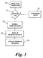
- figure 3 is a flowchart of a bus control process according to the invention.
- The invention proposes to fix the problem of improper configuration of the bus by detecting an improper configuration, and if such configuration is found, by disabling some of the devices connected to the bus before boot.
- In the specific Rambus example, the invention proposes testing the number of devices on the bus, and, if this number is higher than the highest allowable number, by disabling some of the devices connected to the bus before boot. The invention is based on the recognition that even if the number of devices connected to the bus exceeds the highest allowable number, the bus may still operate with only a limited number of devices enabled.
- In the case of the Rambus system, the limitation in the number of modules and devices connected to the bus is apparently due to the sensitivity of the high speed signalling used on the Rambus Channel (the RSL or Rambus Signalling Levels) to the number of loads; the inventors of the present application have realised that a number of loads higher than the highest allowable number has no impact on the control bus, and does not affect the RSL signals for a few devices close to the controller. This makes it possible to disable some devices and to allow the bus to operate in a degraded operation mode. This mode is sufficient for booting a computer, and for allowing a warning to the user, e. g. by displaying a message.
- Figure 3 is a flowchart of a bus control process according to the invention. The process of claim 1 is preferably carried out at the time the bus system is started. In the case of a personal computer, the process of the invention would be carried out in the BIOS of the computer, at the time of computer boot; the necessary computer code would be contained in the relevant memory. In the embodiment of figure 3, the operation of the process of the invention is described in reference to the limitation of the number of devices; the invention also applies similarly to the limitation of the number of modules.
- At
step 20 , which is the first step of the process, the controller 1 reads the control registers of all the devices connected to the bus. In the Rambus, this is made possible by the I2C bus, that accesses the control register even when the number of devices connected to the bus is higher than the highest allowable number. The controller 1 then knows the number of devices connected to the bus channel. - At
step 21, the number of devices connected to the bus channel is compared with the highest allowable number for the channel - in the case of Rambus, 32 devices. If the number of devices is lower than the highest allowable number, or equals this number, the process passes to step 22. Else, if the number of devices is higher than the highest allowable number, the process passes to step 22. - At
step 22, it is ascertained that the number of devices connected to the bus complies with the specification, and the process according to the invention is over. The bus is ready for standard operation, and the operation for which the bus is intended may be carried out. In the case of a computer, standard initialisation and boot process may take place. - At
step 23, it is ascertained that the number of devices connected to the bus violates the bus specification; the controller then enables only some of the devices. This is done with the help of the I2C bus. - The number of devices to be disabled or enabled depends on the specification, and on the total number of devices on the bus. For Rambus, all devices but a limited number are preferably disabled. A number of enabled devices of two has proved appropriate.
- More generally, at this step, the controller may enable from one to five RDRAMs. Enabling one device allows operation of the bus in a degraded mode, and would provide sufficient memory for displaying a message to the user; in other words, one device would be sufficient for copying a warning message to the video control for display on the computer screen. The upper limit on the number of enabled devices depends on the operation of the bus; an upper limit of five devices is appropriate for Rambus, and allows the bus to operate properly. Correct operation of the bus becomes less likely as the number of devices increases.
- Preferably, the enabled devices are the devices adjacent to the controller on the bus channel, so that operation of the bus is possible, even though the number of devices is higher than the highest allowable number of devices. Enabling the devices adjacent to the controller increases the chances that the bus will operate, despite the fact that the number of devices exceeds the highest allowable number. Indeed, the timing constraints are more likely to be satisfied. It is however possible to enable, e. g. the second and third devices, without enabling the first one.
- It is also advantageous to set the parameters of the enabled devices, so as to improve their operation. For Rambus, this may be done by writing in the control registers of the enabled devices, so that these devices work in the same time domain and have optimised timing parameters.
- Thus, at this step, the controller enables some of the devices. The number of enabled devices, and their location are chosen so that the bus operates properly, despite the excessive number of devices. The proper operation of the bus may easily be verified, e.g. by accessing the devices.
- After
step 23, a limited number of devices are enabled, and the bus is ready for operation in a degraded mode. The rest of the process depends on the environment where the bus is used; typically, the machine using the bus may start in a degraded mode, e. g. for warning the user.Steps step 23, the process passes to step 24; the computer starts booting using the enabled devices only. The process then passes to step 25; at this step, a message is displayed to the user, by any available means - for instance by displaying a message on the screen, setting a flag, or turning on a LED or an acoustic signal. The message may suggest a way to fix the problem, and may suggest removing one of the modules so as to reduce the number of modules. - The process then passes to step 25. At
step 25, the machine is made ready for shut down and reboot. - The process of the invention makes it possible to use the bus, in a degraded mode, even when a limitation on the number of devices is violated.
- The description of the preferred embodiment of the invention was made in reference to the Rambus specification. However, the invention also applies to other types of bus systems, where there is provided a controller, a bus, and where the controller may enable or disable devices plugged on the bus, so as to ensure that a physical-layer constraints is respected. For Rambus, the physical layer constraints is assessed as a number of devices. The invention could also apply to other types of physical layer constraints.
- In the Rambus embodiment of the invention, the controller assesses the number of devices, by reading the control register of the modules. The invention also applies to the case where control registers are provided on each device, and not on each module.
Claims (19)
- A bus system comprising a controller (1); a high speed data transfer bus (2), the data transfer bus being subject to one or more inherent physical-layer configuration constraints for proper electrical operation; and a separate control bus (14), said control bus and said data transfer bus connecting the controller and the, or each, device (3, 4, 5, 6) connected thereto, wherein the controller is arranged to communicate with devices using the control bus in order to verify whether or not one or more of the physical-layer configuration constraints are satisfied and, if such configuration constraints are not satisfied, to modify using control signals transmitted on the control bus the operation of at least some of the devices in order to bring the data transfer bus to an operable condition.
- The bus system of claim 1 wherein, if said configuration constraints are not satisfied, the controller is arranged to disable at least some of the devices using control signals transmitted on the control bus in order to bring the data transfer bus to an operable condition.
- The bus system of claim 2 wherein the controller is arranged to disable devices furthest from the controller on the data transfer bus.
- The process of claim 2 or 3, wherein the controller is arranged to disable all devices connected to the bus, except one to five devices.
- The bus system of one of claims 1 to 4, wherein, if said configuration constraints are not satisfied, the controller is arranged to set a stored indicator indicative of a error condition.
- The bus system of one of claims 1 to 5, wherein said physical-layer constraints comprise a constraint on the number of devices connected to the bus.
- In a bus system comprising a controller (1); a high speed data transfer bus (2), the data transfer bus being subject to one or more inherent physical-layer configuration constraints for proper electrical operation; and a separate control bus (14), said control bus and said data transfer bus connecting the controller and the, or each, device (3, 4, 5, 6) connected thereto, a process for bringing the data transfer bus to an operable condition, comprising the steps ofcommunicating with devices using the control bus in order to verify whether or not one or more of the physical-layer configuration constraints are satisfied and,if such configuration constraints are not satisfied, to modifying the operation of at least some of the devices using control signals transmitted on the control bus.
- The process of claim 7 wherein said step of modifying comprises disabling at least some of the devices using control signals transmitted on the control bus.
- The process of claim 8 wherein said step of modifying comprises disabling devices furthest from the controller on the data transfer bus.
- The process of claim 8 or 9 wherein said step of modifying comprises disabling all devices connected to the bus, except one to five devices.
- The process of one of claims 7 to 10 further comprising, if said configuration constraints are not satisfied, setting a stored indicator indicative of a error condition.
- The process of one of claims 7 to 11, wherein said physical-layer constraints comprise a constraint on the number of devices connected to the bus.
- A computer comprising a bus according to one of claims 1 to 6.
- A computer program product for a computer with a bus system comprising a controller (1); a high speed data transfer bus (2), the data transfer bus being subject to one or more inherent physical-layer configuration constraints for proper electrical operation; and a separate control bus (14), said control bus and said data transfer bus connecting the controller and the, or each, device (3, 4, 5, 6) connected thereto,
said computer program product comprising a computer readable medium having thereon :computer program code means, when said program is loaded, to make the controller communicate with devices using the control bus in order to verify whether or not one or more of the physical-layer configuration constraints are satisfied and,if such configuration constraints are not satisfied, to make the controller modify the operation of at least some of the devices using control signals transmitted on the control bus. - The computer program product of claim 14 wherein, if such configuration constraints are not satisfied, the computer program code means make the controller disable at least some of the devices using control signals transmitted on the control bus.
- The computer program product of claim 15 wherein, if such configuration constraints are not satisfied, the computer program code means make the controller disable devices furthest from the controller on the data transfer bus.
- The computer program product of claim 15 or 16 wherein, if such configuration constraints are not satisfied, the computer program code means make the controller disable all devices connected to the bus, except one to five devices.
- The computer program product of one of claims 14 to 17 wherein, if such configuration constraints are not satisfied, the computer program code means set a stored indicator indicative of a error condition.
- The computer program product of one of claims 14 to 18 wherein said physical-layer constraints comprise a constraint on the number of devices connected to the bus.
Priority Applications (1)
| Application Number | Priority Date | Filing Date | Title |
|---|---|---|---|
| EP00202810A EP1077412A3 (en) | 1999-08-16 | 2000-08-10 | Bus system having improved control process |
Applications Claiming Priority (3)
| Application Number | Priority Date | Filing Date | Title |
|---|---|---|---|
| EP99410099 | 1999-08-16 | ||
| EP99410099 | 1999-08-16 | ||
| EP00202810A EP1077412A3 (en) | 1999-08-16 | 2000-08-10 | Bus system having improved control process |
Publications (2)
| Publication Number | Publication Date |
|---|---|
| EP1077412A2 true EP1077412A2 (en) | 2001-02-21 |
| EP1077412A3 EP1077412A3 (en) | 2004-12-15 |
Family
ID=26072583
Family Applications (1)
| Application Number | Title | Priority Date | Filing Date |
|---|---|---|---|
| EP00202810A Withdrawn EP1077412A3 (en) | 1999-08-16 | 2000-08-10 | Bus system having improved control process |
Country Status (1)
| Country | Link |
|---|---|
| EP (1) | EP1077412A3 (en) |
Cited By (4)
| Publication number | Priority date | Publication date | Assignee | Title |
|---|---|---|---|---|
| WO2004109525A2 (en) * | 2003-06-03 | 2004-12-16 | Intel Corporation | Memory module architecture daisy chain topology detects and reports presence of outer memory module to inner module |
| US7383399B2 (en) | 2004-06-30 | 2008-06-03 | Intel Corporation | Method and apparatus for memory compression |
| CN101599055B (en) * | 2009-07-24 | 2010-08-11 | 原亮 | Embedded isomerism CPU array system based on correlative bus |
| WO2013040409A1 (en) * | 2011-09-15 | 2013-03-21 | Teletech Holdings, Inc. | Method for activating services associated with a product via a service center supporting a variety of products |
Citations (4)
| Publication number | Priority date | Publication date | Assignee | Title |
|---|---|---|---|---|
| EP0158774A2 (en) * | 1984-03-30 | 1985-10-23 | International Business Machines Corporation | Data processing system with an improved storage testing device |
| US4570220A (en) * | 1983-11-25 | 1986-02-11 | Intel Corporation | High speed parallel bus and data transfer method |
| DE3928998A1 (en) * | 1989-09-01 | 1991-03-07 | Licentia Gmbh | Programmable memory controller with parallel bus connection - has serial bus for economical independent inter-slave communications, with one slave acting as master |
| US5430859A (en) * | 1991-07-26 | 1995-07-04 | Sundisk Corporation | Solid state memory system including plural memory chips and a serialized bus |
-
2000
- 2000-08-10 EP EP00202810A patent/EP1077412A3/en not_active Withdrawn
Patent Citations (4)
| Publication number | Priority date | Publication date | Assignee | Title |
|---|---|---|---|---|
| US4570220A (en) * | 1983-11-25 | 1986-02-11 | Intel Corporation | High speed parallel bus and data transfer method |
| EP0158774A2 (en) * | 1984-03-30 | 1985-10-23 | International Business Machines Corporation | Data processing system with an improved storage testing device |
| DE3928998A1 (en) * | 1989-09-01 | 1991-03-07 | Licentia Gmbh | Programmable memory controller with parallel bus connection - has serial bus for economical independent inter-slave communications, with one slave acting as master |
| US5430859A (en) * | 1991-07-26 | 1995-07-04 | Sundisk Corporation | Solid state memory system including plural memory chips and a serialized bus |
Cited By (8)
| Publication number | Priority date | Publication date | Assignee | Title |
|---|---|---|---|---|
| WO2004109525A2 (en) * | 2003-06-03 | 2004-12-16 | Intel Corporation | Memory module architecture daisy chain topology detects and reports presence of outer memory module to inner module |
| WO2004109525A3 (en) * | 2003-06-03 | 2005-01-27 | Intel Corp | Memory module architecture daisy chain topology detects and reports presence of outer memory module to inner module |
| US7194581B2 (en) | 2003-06-03 | 2007-03-20 | Intel Corporation | Memory channel with hot add/remove |
| US7383399B2 (en) | 2004-06-30 | 2008-06-03 | Intel Corporation | Method and apparatus for memory compression |
| CN101599055B (en) * | 2009-07-24 | 2010-08-11 | 原亮 | Embedded isomerism CPU array system based on correlative bus |
| WO2013040409A1 (en) * | 2011-09-15 | 2013-03-21 | Teletech Holdings, Inc. | Method for activating services associated with a product via a service center supporting a variety of products |
| US9173090B2 (en) | 2011-09-15 | 2015-10-27 | Teletech Holdings, Inc. | Method for activating services associated with a product via a service center supporting a variety of products |
| US10009759B2 (en) | 2011-09-15 | 2018-06-26 | Teletech Holdings, Inc. | Method and system for enabling and activating a functionality of an electronic device |
Also Published As
| Publication number | Publication date |
|---|---|
| EP1077412A3 (en) | 2004-12-15 |
Similar Documents
| Publication | Publication Date | Title |
|---|---|---|
| EP0552873B1 (en) | Modifying system configuration in a computer system | |
| US5920709A (en) | Bus interface for IDE device | |
| US6487623B1 (en) | Replacement, upgrade and/or addition of hot-pluggable components in a computer system | |
| US6572384B1 (en) | Method and apparatus for interconnecting circuit cards | |
| US5628027A (en) | Method of determining the configuration of devices installed on a computer bus | |
| US5905888A (en) | Bootable redundant hard disk attached to a PC's parallel port with rom-address auto-detect and configure during BIOS scan | |
| US6401157B1 (en) | Hot-pluggable component detection logic | |
| US5119498A (en) | Feature board with automatic adjustment to one of two bus widths based on sensing power level at one connection contact | |
| JP3549410B2 (en) | Accessory resource offset mechanism | |
| KR100764921B1 (en) | Virtual rom for device enumeration | |
| US20100268874A1 (en) | Method of configuring non-volatile memory for a hybrid disk drive | |
| US5948076A (en) | Method and system for changing peripheral component interconnect configuration registers | |
| US20050041459A1 (en) | Interface for removable storage devices | |
| US8677084B2 (en) | Method of configuring non-volatile memory for a hybrid disk drive | |
| EP1372069A2 (en) | Method system and software for configuring a graphics processing communication mode | |
| US7080164B2 (en) | Peripheral device having a programmable identification configuration register | |
| US5214771A (en) | System for loading same type adaptors with latest version control codes stored on adaptor memory by selecting the identified chip during initialization | |
| CN107145198B (en) | Method for improving compatibility of server to hard disk and mainboard thereof | |
| US7103695B2 (en) | System and method for scaling a bus based on a location of a device on the bus | |
| JP2016206912A (en) | Electronic device, control apparatus, automated teller machine, and usb connector monitoring program | |
| US6957289B2 (en) | Bus system having improved control process | |
| US6647451B1 (en) | Basic input/output integration of motherboard extension features and plug and play information delivery | |
| EP1077412A2 (en) | Bus system having improved control process | |
| US7047565B2 (en) | Method and system for capturing in-service date information | |
| US6092134A (en) | Method and apparatus for locking out a processor in a computer system with a bus that is improperly terminated |
Legal Events
| Date | Code | Title | Description |
|---|---|---|---|
| PUAI | Public reference made under article 153(3) epc to a published international application that has entered the european phase |
Free format text: ORIGINAL CODE: 0009012 |
|
| AK | Designated contracting states |
Kind code of ref document: A2 Designated state(s): AT BE CH CY DE DK ES FI FR GB GR IE IT LI LU MC NL PT SE |
|
| AX | Request for extension of the european patent |
Free format text: AL;LT;LV;MK;RO;SI |
|
| RAP1 | Party data changed (applicant data changed or rights of an application transferred) |
Owner name: HEWLETT-PACKARD COMPANY, A DELAWARE CORPORATION |
|
| PUAL | Search report despatched |
Free format text: ORIGINAL CODE: 0009013 |
|
| AK | Designated contracting states |
Kind code of ref document: A3 Designated state(s): AT BE CH CY DE DK ES FI FR GB GR IE IT LI LU MC NL PT SE |
|
| AX | Request for extension of the european patent |
Extension state: AL LT LV MK RO SI |
|
| RIC1 | Information provided on ipc code assigned before grant |
Ipc: 7G 06F 13/42 B Ipc: 7G 06F 11/00 B Ipc: 7G 06F 9/445 B Ipc: 7G 06F 13/40 A |
|
| 17P | Request for examination filed |
Effective date: 20050304 |
|
| AKX | Designation fees paid |
Designated state(s): AT BE CH CY DE DK ES FI FR GB GR IE IT LI LU MC NL PT SE |
|
| STAA | Information on the status of an ep patent application or granted ep patent |
Free format text: STATUS: THE APPLICATION IS DEEMED TO BE WITHDRAWN |
|
| 18D | Application deemed to be withdrawn |
Effective date: 20080301 |