EP1079883B1 - Guidewire and catheter locking device and method - Google Patents
Guidewire and catheter locking device and method Download PDFInfo
- Publication number
- EP1079883B1 EP1079883B1 EP99908507A EP99908507A EP1079883B1 EP 1079883 B1 EP1079883 B1 EP 1079883B1 EP 99908507 A EP99908507 A EP 99908507A EP 99908507 A EP99908507 A EP 99908507A EP 1079883 B1 EP1079883 B1 EP 1079883B1
- Authority
- EP
- European Patent Office
- Prior art keywords
- catheter
- guide wire
- locking device
- lumen
- opening
- Prior art date
- Legal status (The legal status is an assumption and is not a legal conclusion. Google has not performed a legal analysis and makes no representation as to the accuracy of the status listed.)
- Expired - Lifetime
Links
Images


Classifications
-
- A—HUMAN NECESSITIES
- A61—MEDICAL OR VETERINARY SCIENCE; HYGIENE
- A61M—DEVICES FOR INTRODUCING MEDIA INTO, OR ONTO, THE BODY; DEVICES FOR TRANSDUCING BODY MEDIA OR FOR TAKING MEDIA FROM THE BODY; DEVICES FOR PRODUCING OR ENDING SLEEP OR STUPOR
- A61M25/00—Catheters; Hollow probes
- A61M25/01—Introducing, guiding, advancing, emplacing or holding catheters
- A61M25/0169—Exchanging a catheter while keeping the guidewire in place
-
- A—HUMAN NECESSITIES
- A61—MEDICAL OR VETERINARY SCIENCE; HYGIENE
- A61M—DEVICES FOR INTRODUCING MEDIA INTO, OR ONTO, THE BODY; DEVICES FOR TRANSDUCING BODY MEDIA OR FOR TAKING MEDIA FROM THE BODY; DEVICES FOR PRODUCING OR ENDING SLEEP OR STUPOR
- A61M25/00—Catheters; Hollow probes
- A61M25/0097—Catheters; Hollow probes characterised by the hub
-
- A—HUMAN NECESSITIES
- A61—MEDICAL OR VETERINARY SCIENCE; HYGIENE
- A61M—DEVICES FOR INTRODUCING MEDIA INTO, OR ONTO, THE BODY; DEVICES FOR TRANSDUCING BODY MEDIA OR FOR TAKING MEDIA FROM THE BODY; DEVICES FOR PRODUCING OR ENDING SLEEP OR STUPOR
- A61M25/00—Catheters; Hollow probes
- A61M25/01—Introducing, guiding, advancing, emplacing or holding catheters
- A61M25/0172—Exchanging a guidewire while keeping the catheter in place
-
- A—HUMAN NECESSITIES
- A61—MEDICAL OR VETERINARY SCIENCE; HYGIENE
- A61M—DEVICES FOR INTRODUCING MEDIA INTO, OR ONTO, THE BODY; DEVICES FOR TRANSDUCING BODY MEDIA OR FOR TAKING MEDIA FROM THE BODY; DEVICES FOR PRODUCING OR ENDING SLEEP OR STUPOR
- A61M25/00—Catheters; Hollow probes
- A61M25/01—Introducing, guiding, advancing, emplacing or holding catheters
- A61M25/02—Holding devices, e.g. on the body
-
- A—HUMAN NECESSITIES
- A61—MEDICAL OR VETERINARY SCIENCE; HYGIENE
- A61M—DEVICES FOR INTRODUCING MEDIA INTO, OR ONTO, THE BODY; DEVICES FOR TRANSDUCING BODY MEDIA OR FOR TAKING MEDIA FROM THE BODY; DEVICES FOR PRODUCING OR ENDING SLEEP OR STUPOR
- A61M25/00—Catheters; Hollow probes
- A61M25/01—Introducing, guiding, advancing, emplacing or holding catheters
- A61M25/09—Guide wires
- A61M25/09041—Mechanisms for insertion of guide wires
-
- A—HUMAN NECESSITIES
- A61—MEDICAL OR VETERINARY SCIENCE; HYGIENE
- A61M—DEVICES FOR INTRODUCING MEDIA INTO, OR ONTO, THE BODY; DEVICES FOR TRANSDUCING BODY MEDIA OR FOR TAKING MEDIA FROM THE BODY; DEVICES FOR PRODUCING OR ENDING SLEEP OR STUPOR
- A61M25/00—Catheters; Hollow probes
- A61M25/01—Introducing, guiding, advancing, emplacing or holding catheters
- A61M2025/0183—Rapid exchange or monorail catheters
-
- A—HUMAN NECESSITIES
- A61—MEDICAL OR VETERINARY SCIENCE; HYGIENE
- A61M—DEVICES FOR INTRODUCING MEDIA INTO, OR ONTO, THE BODY; DEVICES FOR TRANSDUCING BODY MEDIA OR FOR TAKING MEDIA FROM THE BODY; DEVICES FOR PRODUCING OR ENDING SLEEP OR STUPOR
- A61M25/00—Catheters; Hollow probes
- A61M25/01—Introducing, guiding, advancing, emplacing or holding catheters
- A61M25/09—Guide wires
- A61M2025/09125—Device for locking a guide wire in a fixed position with respect to the catheter or the human body
-
- Y—GENERAL TAGGING OF NEW TECHNOLOGICAL DEVELOPMENTS; GENERAL TAGGING OF CROSS-SECTIONAL TECHNOLOGIES SPANNING OVER SEVERAL SECTIONS OF THE IPC; TECHNICAL SUBJECTS COVERED BY FORMER USPC CROSS-REFERENCE ART COLLECTIONS [XRACs] AND DIGESTS
- Y10—TECHNICAL SUBJECTS COVERED BY FORMER USPC
- Y10T—TECHNICAL SUBJECTS COVERED BY FORMER US CLASSIFICATION
- Y10T24/00—Buckles, buttons, clasps, etc.
- Y10T24/34—Combined diverse multipart fasteners
- Y10T24/3427—Clasp
- Y10T24/3439—Plural clasps
- Y10T24/344—Resilient type clasp
- Y10T24/3444—Circular work engageable
Definitions
- the present invention relates to a guide wire and/or a catheter locking device for use in catheter procedures within the human anatomy, and methods of using the same.
- the locking device is particularly useful during catheter exchange procedures.
- the present invention includes a locking device that is attached to an endoscope, a guide catheter, or other guiding type catheter that receives a guide wire and/or another catheter.
- the locking device is used to selectively secure the guide wire and/or catheter in a desired position within the endoscope or guiding type catheter. This may reduce the likelihood that the guide wire and/or catheter will move from a desired placement during a procedure, such as a catheter exchange procedure.
- Endoscopic procedures for treating abnormal pathologies within the alimentary canal system and biliary tree are increasing in number.
- the endoscope provides access to the general area of a desired duct using direct visualization.
- the duct itself must be navigated using a catheter in conjunction with fluoroscopy and guide wires.
- Catheters are known for treatment of targeted anatomical regions.
- Known methods and devices for using biliary catheters for accessing the biliary tree for performing catheter procedures are disclosed in Weaver et al., U.S. Patent No. 5,397,302 and Karpiel.
- an endoscope is first introduced into the mouth of the patient.
- the endoscope includes a proximal end and a distal end, and has a lumen extending longitudinally between the proximal and distal ends.
- the endoscope is guided through the patient's alimentary tract or canal until an opening at the distal end of the endoscope is proximate the area to receive treatment. At this point, the endoscope allows other components, such as a catheter, to access the targeted area.
- the distal end of the endoscope is positioned proximate the papilla of vater leading to the common bile duct and the pancreatic duct.
- a catheter is guided through the lumen of the endoscope until a distal tip of the catheter emerges from the opening at the distal end of the endoscope.
- the catheter may be used for accessing the biliary tree.
- the distal end of the catheter is guided through the orifice to the papilla of vater (located between the sphincter of oddi) leading to the common bile duct and the pancreatic duct.
- a guide wire may be used in conjunction with the catheter to facilitate accessing a desired location within the biliary tree.
- the guide wire is inserted in an opening at a proximal end of the catheter and guided through the catheter until it emerges from the distal end of the catheter.
- the guide wire is guided into the common bile duct.
- the catheter is advanced over the guide wire, as previously described, until the distal end of the catheter is positioned in the common bile duct at the desired location.
- the catheter is now in position for delivery of contrast media for fluoroscopic visualization of anatomical detail within the common bile duct.
- Visualization may reveal selected areas within the common bile duct that require treatment.
- a different catheter is typically required, necessitating a catheter exchange.
- a catheter exchange typically involves removing the first catheter from the endoscope over the guide wire, and advancing a second catheter over the guide wire to the desired treatment site.
- a guide wire exchange procedure In addition to performing a catheter exchange procedure, it may also be desirable to perform a guide wire exchange procedure This may be desirable when, for example, a first guide wire is too large to fit through a desired body duct, or otherwise lacks the desired characteristics. Under these circumstances, a physician may leave the catheter in place, withdraw the first guide wire from the catheter, and insert a second guide wire through the catheter to the desired site. During this procedure, the catheter guides the guide wire to the desired site. Thus, once the catheter is positioned at a target site, it is highly desirable to maintain the position of the catheter during a guide wire exchange procedure so that the second guide wire may be guided directly to the desired site in a minimum amount of time.
- a physician typically must grasp the proximal end of the guide wire and/or catheter with one hand, and performing the corresponding exchange with the other. This is difficult, and often results in the movement of the guide wire and/or catheter. Therefore, it would be desirable to provide a locking device whereby the physician can secure the position of the guide wire and/or catheter during an exchange procedure, thereby freeing both hands to perform other tasks.
- the present invention overcomes many of the disadvantages of the prior art by providing a locking device that is mounted on an endoscope or the like for selectively securing the position of a guide wire and/or catheter relative to the endoscope or the like.
- the locking device preferably includes a side wall with an opening therein for receiving the guide wire or catheter near its proximal end or at any point along the guide wire or catheter's length depending upon how far it is inserted.
- the opening is preferably J-shaped or boot shaped, and has an entry slot and a locking slot.
- the locking device includes a body member that is funnel shaped including a horn and a neck with a lumen extending therethrough.
- the horn has a side wall with an opening provided therein.
- the neck is operatively attached to the endoscope or the like proximate an access port.
- a proximal portion of the guide wire or catheter extends out of the access port of the endoscope or the like and through the lumen of the locking device.
- the locking device is adapted for use with an endoscope having a side port.
- the side port is in fluid communication with one or more lumens, and may receive a guide wire or catheter therein.
- the locking device includes a body member, an attachment mechanism and a securing mechanism.
- the attachment mechanism preferably includes one or more hook members that engage the main shaft of the endoscope near the side port. These hook members tend to clip or secure the locking device to the main shaft of the endoscope.
- the body member extends from the hook members generally parallel to the side port.
- the securing mechanism which is preferably an opening in the body member, is preferably positioned near the end of the body member and proximate the side port opening of the endoscope.
- the proximal portion of the guide wire or catheter which extends outside of the side port of the endoscope, may be moved into the opening of the locking device and frictionally fit therein.
- the opening includes an entry slot and a locking slot, as described above.
- the locking device may include more than one securing mechanism for securing more than one guide wire or catheter or combination of guide wires and catheters. This is preferably accomplished by including two or more openings in the body member of the locking device.
- one opening may be substantially J-shaped for securing a guide wire.
- Another opening may be boot shaped for securing a catheter. The boot shape is similar to the J-shape but has increased dimensions for receiving the larger catheter shaft.
- a guide wire or catheter may be inserted into the lumen of an endoscope or the like.
- the locking device which is preferably operatively attached to the shaft of the endoscope or the like, has a wall with an opening therein.
- the opening is preferably positioned proximate an access port of the endoscope or the like.
- the opening preferably has a locking slot that has a reduced dimension relative to the outside portion of the guide wire or catheter.
- the locking device may be used in conjunction with any catheter that receives another device such as a guide wire or another catheter.
- the locking device may be used in conjunction with endoscopes, guide catheters, angioplasty catheters, etc.
- the first and second catheters should be rapid-exchange type catheters to allow access to the guide wire proximate the access port during at least most of the catheter exchange procedure.
- Fig 1. shows a perspective view of a catheter assembly 30 in accordance with the present invention.
- Catheter assembly 30 is used in catheter procedures for accessing targeted anatomical regions through the alimentary canal.
- the present invention incorporates features which allow rapid exchange of a catheter by a single operator.
- the catheter of the present invention allows shorter length guide wires to be used, resulting in procedures which require less medical personnel, are less time consuming, and less costly. Additionally, the present invention is adaptable to most catheter devices used for catheter procedures within the alimentary canal.
- Catheter assembly 30 includes a catheter hub assembly 32 and a catheter 34, having a guide wire 36 passing through a portion thereof.
- Catheter 34 includes a shaft 38, which in general terms has a proximal end 40, a U-channel 42, a distal tip region 44, a distal end 46 and various lumens described in greater detail below.
- Catheter hub assembly 32 is operably connected to proximal end 40 of shaft 38.
- Catheter hub assembly 32 is preferably configured to couple to ancillary devices allowing access to a lumen within shaft 38.
- Shaft 38 is a generally tubular shaped member having a generally uniform outer shape at proximal end 40. Shaft 38 may be sized for slidable passage through the lumen of an endoscope (not shown). Shaft 38 is preferably formed in an extrusion process. Shaft 38 may be formed of an extruded polymeric material. In one embodiment, the preferred polymeric material is polytetrafluoroethylene, polyether block amide, nylon or a combination or blend of these. Catheters which are contemplated include, but are not limited to, cannulas, sphincterotomes, cytology devices, and devices for stone retrieval and stent placement.
- shaft 38 further includes a distal taper 48 which tapers to distal tip region 44.
- tip region 44 may include high contrast, color coded distal markers 50.
- distal end 46 may be radiopaque for fluoroscopic visualization of distal tip region 44 during a catheter procedure.
- U-channel 42 of shaft 38 extends between a first, proximal channel end 52 and a second, distal channel end 54.
- U-channel 42 serves to contain, but not necessarily constrain, guide wire 36, between channel proximal end 52 and channel distal end 54.
- the term "U-channel” refers to a channel shape that allows radial removal of guide wire 36 from the channel 42, and need not be strictly in the shape of the letter U.
- Channel 42 in the preferred embodiment is sufficiently large to allow unhindered radial guide wire 36 movement out of channel 42.
- the channel walls and radial opening are substantially equal to or slightly larger than the diameter of a guide wire lumen, described in greater detail below.
- proximal channel end 52 may be located at any location distal of proximal end 40 of shaft 38
- channel distal end 54 is preferably located between 10 and 40 cm from distal end 46 of catheter shaft 38.
- Fig. 1A which is a cross-sectional view of shaft 38 taken along line 1A-1A at a location proximal of channel proximal end 52, shaft 38 includes ancillary lumen 56, ancillary lumen 58 and guide wire lumen 60.
- Ancillary lumen 56 and ancillary lumen 58 extend longitudinally between proximal end 40 and distal end 46 of shaft 38.
- Ancillary lumen 56 and ancillary lumen 58 may be injection lumens, allowing for high contrast media flow capability for bubble-free opacification and for excellent visualization of a desired anatomical region. Additionally or alternatively, ancillary lumen 56 and/or ancillary lumen 58 may be used for or as part of other ancillary devices, such as a cutting wire lumen or a retrieval balloon lumen.
- Guide wire lumen 60 extends longitudinally between proximal end 40 and distal end 46 of shaft 38 in the preferred embodiment. Further, guide wire lumen 60 is sized to receive guide wire 36. Guide wire lumen 60 may be a tubular member which is extruded integral catheter shaft 38, or alternatively, guide wire lumen 60 may be a separate tubular member which is coupled to catheter shaft 38. Although in one preferred embodiment the guide wire lumen 60 is a tubular member which is located proximate distal end 46 of catheter shaft 38, it is recognized that guide wire lumen 60 may be formed anywhere along shaft 38, may be an extension of shaft 38 coupled to distal end 46, or guide wire lumen 60 may run the entire length of shaft 38.
- Guide wire 36 may access guide wire lumen 60 at a point proximal channel distal end 54.
- Guide wire 36 extends within channel 42 to channel distal end 54, continuing within guide wire lumen 60 through distal tip region 44, and exiting through an opening in distal end 46.
- a section of catheter shaft 38 having U-channel 42 is shown.
- the embodiment shown also includes ancillary lumens 56 and 58.
- Sections of shaft 38 proximate the channel proximal end 52 and distal channel distal end 54 contain guide wire lumen 60 in communication with U-channel 42.
- U-channel 42 has an interior, closed-side geometry, substantially the same as the geometry of guide wire lumen 60. Further, U-channel 42 walls are spaced further than a diameter of guide wire 36 such that guide wire 36 moves freely into and out of U-channel 42.
- Catheter shaft 38 can be configured such that U-channel 42 is defined separately from guide wire lumen 60.
- guide wire lumen 60 is divided into two sections; a first section extending between proximal end 40 of shaft 38 and channel proximal end 52; and a second portion extending between channel distal end 54 and distal end 46 of shaft 38.
- the shaft can be configured to define guide wire lumen 60 as extending longitudinally between proximal end 40 and distal end 46 of shaft 38.
- guide wire lumen 60 is integral with U-channel 42.
- guide wire lumen 60 defines a portion of U-channel 42 such that spacing between outer walls of U-channel 42 is equal to a diameter of guide wire lumen 60. Regardless of how guide wire lumen 60 and U-channel 42 are defined.
- U-channel 42 provides for access to guide wire lumen 60 at channel distal end 54. In this regard, channel distal end 54 can be enlarged to more easily direct guide wire 36 into guide wire lumen 60.
- Guide wire lumen 60 and U-channel 42 allow rapid exchange of catheter assembly 30 when an alternative catheter is necessary during a certain medical procedure. Shorter length guide wires may be used since guide wire 36 does not pass through shaft proximal end 40 and hub assembly 32, but rather exits the catheter shaft 38 at U-channel 42 located substantially distal from proximal end 40.
- the unique catheter construction in accordance with the present invention will reduce catheter therapeutic and diagnostic procedure time since catheter device exchanges may be performed relatively more easily and quickly by a single operator. Additional personnel and time associated with maintaining the placement of a conventional (approximately 400 cm) guide wire within the targeted anatomical region is eliminated, reducing the overall costs of the procedure.
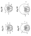
- FIG. 2A illustrates catheter shaft 38 having ancillary lumens 56 and 58, U-channel 42, and guide wire 36 within U-channel 42. Further, shaft 38 is shown within a first size endoscope working channel 70.
- guide wire 36 is effectively radially constrained by small sized working channel 70 that closely surrounds U-channel 42.
- Fig. 2B illustrates catheter containment within a second size working channel 72, slightly larger than the working channel 70 of Fig. 2A.
- guide wire 36 is able to move out of U-channel 42 to a position denoted with dashed lines at 80.
- Fig. 2C shows shaft 38 contained within a third, even larger sized working channel 74.
- Guide wire 36 is able to move completely out of U-channel 42 to position 82 shown with dashed lines.
- Fig. 2D demonstrates catheter shaft 38 within a fourth size working channel 76. In this even larger working channel, guide wire 36 lies within an even larger cross-sectional area, and is able to move to a position shown in FIG. 2D with dashed lines at 84.
- an exchange sheath having a sufficiently small inner diameter so as to constrain guide wire movement to within the catheter U-channel 42 is employed with the preferred embodiment.
- an endoscope exchange sheath in accordance with the preferred embodiment allows for use of a radially accessible guide wire, which is longitudinally aligned with the catheter, while presenting a circular profile to an endoscope and mitigating guide wire pinching problems between the catheter and the endoscope working channel wall.
- an endoscope exchange sheath assembly 100 having sheath hub assembly 102 and a sheath 104 is shown.
- the sheath 104 includes a lumen 106 and a distal end 108.
- Fig. 3A shows a section of sheath 104, having lumen 106 for receiving a catheter.
- catheter 34 is fed through lumen 106 of sheath 104 such that sheath 104 encompasses guide wire 36 within U-channel 42.
- Sheath 104 is adapted to be disposed within an endoscope working channel, thereby providing a smaller diameter channel than that of the surrounding endoscope working channel constraining the guide wire 36 (Fig. 1) to the U-channel 42 (Fig. 1), and mitigating the potential problems shown in Figs. 2C and 2D.
- Sheath assembly 110 includes a two-piece hub assembly 112 and a sheath 114 defining lumen 116 and having slit 118 extending longitudinally over its length, terminating at distal end 120. Slit 118 in sheath 114 is shown in more detail in Fig. 4B.
- two-piece hub assembly 112 has a proximal hub portion 122 and a distal hub portion 124, having a proximal slit 126 and a distal slit 128, respectively.
- Sheath slit 118 is in communication with hub slits 126 and 128, allowing a guide wire (not shown) to be radially slid into or out of sheath assembly 110.
- Proximal hub portion 122 is shown unlocked (position "A") in Fig. 4, aligning hub proximal slit 126 with hub distal slit 128 and sheath slit 118, providing a continuous slit for guide wire radial movement into and out of the sheath assembly 110.
- Proximal hub portion 122 is shown locked, in position "B", in Fig. 4A, whereby proximal hub slit 126 is rotated with respect to distal hub slit 128, preventing a guide wire (not shown) within hub assembly 112 from being moved radially out of hub assembly 112.
- Proximal hub portion 122 is set to position B (Fig. 4A) when radial guide wire movement is not desired.
- Fig. 4C illustrates a portion of an alternate embodiment sheath 130 having a lumen 132, a sheath wall opening 134 and sheath wall overlap 136.
- a guide wire (not shown) is able to be slid out of lumen 132 of sheath 130 by maneuvering the guide wire into sheath wall opening 134 and through overlap 136.
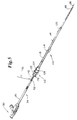
- catheter assembly 30 depicted in Fig. 1 is shown inserted within endoscope exchange sheath assembly 110 depicted in Fig. 4. More particularly, catheter 34 is inserted through slitted sheath assembly 110, extending distally out sheath distal end 120.
- Guide wire 36 (shown partially in Fig. 5) is positioned within U-channel 42 of catheter 34, along guide wire lumen 60 (Fig. 1B), and extends from shaft distal end 46. Further, guide wire 36 is engaged by hub assembly 112. More particularly, guide wire 36 passes within and is engaged by proximal slit 126 and distal slit 128 of hub assembly 112.
- Sheath proximal hub portion 122 having proximal slit 126, is shown in locked position relative to sheath distal hub portion 124, having distal slit 128.
- hub assembly 112 of sheath assembly 110 prevents radial withdrawal of guide wire 36, otherwise inserted in U-channel 42 of catheter 34, from distal the channel proximal end 52.
- Fig. 6 a section of Fig. 5 is shown in detail, having endoscope sheath 114 containing catheter shaft 38, which further maintains guide wire 36 within U-channel 42.
- sheath 114 is able to constrain movement of guide wire 36 from U-channel 42 when sheath 114 is within a larger endoscope working channel, for example as illustrated in Figs. 2C and 2D.
- the sheath 114 embodiment illustrated in Fig. 6 includes longitudinal slit 118, allowing guide wire 36 to be peeled from catheter shaft 38 and endoscope sheath 114.
- U-channel 42 is sized larger than guide wire 36 such that guide wire 36 can displace radially from U-channel 42.
- Sheath 114 prevents undesired displacement of guide wire 36 from U-channel 42 under normal operating conditions. However, if adequate radial force is placed on guide wire 36 by an operator, guide wire 36 will separate sheath 114 along slit 118 such that guide wire 36 is displaced from sheath 114 and U-channel 42.
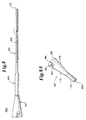
- guide wire 36 is shown inserted within catheter assembly 30 of Fig 1, which is inserted through endoscope sheath assembly 110 of Fig 4, which is in turn within an endoscope 150.
- Sheath assembly 110 includes sheath 114 that has slit 118 and two-piece hub assembly 112, shown at a locked position "B" (also in Fig. 4A). Having hub assembly 112 locked prevents guide wire 36 from moving radially out of sheath 114 through slit 118.
- Guide wire 36 can be restrained from longitudinal movement by applying finger pressure on the guide wire 36 against hub assembly 112.
- endoscope 150 and sheath assembly 110 of Fig. 7 are shown without the catheter assembly 30 inserted, as after catheter withdrawal.
- Sheath hub assembly 112 is shown in unlocked position at "A" (also in Fig. 4). Having hub assembly 112 unlocked allows radial movement of guide wire 36 out of sheath 114 through slit 118, but such movement may be restrained by trapping guide wire 36 against the outside of sheath 114 using one finger, providing ease of guide wire 36 control during catheter exchanges.
- an endoscope 150 is first introduced into the mouth of a patient and is guided through the patient's alimentary canal. Specifically, endoscope 150 is guided down the esophagus, through the stomach, past the pyloric sphincter of the stomach and into the duodenum. Endoscope 150 has a lumen extending longitudinally between its proximal end and the distal end.
- Endoscope 150 is guided through the alimentary canal until a distal end (not shown) of endoscope 150 is proximate the target area within the anatomy to receive treatment.
- endoscope 150 is guided into the duodenum until the opening at the distal end of the endoscope 150 is proximate the papilla of vater.
- the papilla of vater is located between the sphincter of oddi, which leads to the common bile duct, hepatic, and pancreatic ducts.
- the proximal end (shown in Figs. 7 and 7A) of endoscope 150 extends and remains outside the mouth of the patient.
- catheter assembly 30 is prepared for insertion into the endoscope.
- guide wire 36 is fed into the guide wire lumen 60 (Figs. 1A-1C) of shaft 38. More particularly, a distal end of guide wire 36 is placed within U-channel 42, distal the channel proximal end 52. The guide wire 36 is then fed to channel distal end 54 (Fig. 1) into guide wire lumen 60. Finally, guide wire 36 is fed through shaft 38 to distal tip region 40 (Fig. 1).
- catheter 34 is then inserted directly into endoscope 150 working channel. This method may be practiced with an endoscope having a sufficiently small working channel inside diameter, as illustrated in Fig. 2A, to constrain guide wire 36 movement without a sheath.
- catheter assembly 30, threaded with guide wire 36 is inserted into sheath assembly 110, thereby constraining guide wire 36 from slipping radially out of U-channel 42. More particularly, catheter 34 is inserted into endoscope 150 working channel, but leaving channel proximal end 52 proximate sheath hub assembly 112, and leaving a portion of guide wire 36 extending from the channel proximal end 52 as well.
- sheath hub assembly 112 includes hub slits 126 and 128 which receive a portion of guide wire 36.
- hub assembly 112 is locked, preventing unwanted radial guide wire 36 movement.
- the loading of guide wire 34 into catheter shaft 38 and catheter shaft 38 into sheath assembly 110 is done prior to inserting endoscope 150 into a patient (not shown).
- Endoscope sheath 114 containing catheter shaft 38, is inserted into endoscope 150 working channel. Endoscope sheath 114 serves to constrain radial guide wire 36 movement over the approximate length of U-channel 42. Catheter shaft 38 and sheath 114 are inserted together into endoscope 150 until both are near a distal end (not shown) of endoscope 150. Catheter shaft 38 and sheath 114 may be, either or both, advanced until exiting the distal end of endoscope 150.
- guide wire 36 is advanced until guide wire 36 distal tip is positioned within the target area in the biliary tree (including the common bile, hepatic or pancreatic ducts).
- the distal tip of guide wire 36 may be guided through the orifice leading to the papilla of vater for access to the biliary tree.
- Catheter shaft 38 may then be advanced over guide wire 36, tracking catheter assembly 30, until catheter distal up region 40 (Fig. 1) exits distal end of endoscope 150 and is positioned within the desired duct.
- guide wire 36 and catheter assembly 30 are advanced together until catheter distal end 42 (Fig. 1) is positioned at the target area. It is also recognized that the catheter could be first advanced to near the target area, followed by inserting the guide wire when needed to advance the catheter further.
- catheter procedures including injecting contrast media, such as radiopaque dye, through ancillary lumens 56 or 58 (Fig. 1A-1C) into the common bile duct for visualization of the duct, can be performed.
- catheter assembly 30 can be exchanged or removed from endoscope 150, leaving guide wire 36 in position for other catheter procedures.
- Catheter assembly 30 and sheath assembly 110 may also be removed together.
- One method of withdrawing catheter 34 from endoscope 150 is possible using either a slitted/overlapped endoscope sheath 114 as depicted in Figs. 4 through 4C, or a sheath 104 without a slit as depicted in Figs. 3 through 3A.
- guide wire 36 is held to prevent longitudinal movement while catheter 34 is retracted within endoscope sheath 114 (or 104).
- Catheter 34 retraction leaving the guide wire 36 in position within the patient is enabled by U-channel 42 being radially open to guide wire 36 removal in catheter shaft 38. Once catheter retraction has brought channel distal end 54 (Fig.
- the distal end of the endoscope can include an elevator which could be utilized to lock the distal end of the guide wire in position while the catheter is removed.
- Exchange of endoscope sheath assembly 110 may be desired, as when a stent (not shown) is to be advanced over guide wire 36, and the stent has a larger outside diameter than can be accommodated by the sheath 114.
- One method of exchanging an endoscope sheath assembly 110 may be used where sheath 114 is slitted as in Fig. 4B, or overlapped, as in sheath 130 in Fig. 4C. Referring to Fig. 7A, two-piece hub assembly 112 is turned to the unlocked position "A" (also shown in Fig. 4). Guide wire 36 is pulled radially away from sheath hub assembly 112 and through slit 118 in sheath 114.
- Guide wire 36 is then held, preferably against some portion of endoscope 150, to prevent guide wire 36 from being dislodged from position within the patient.
- Sheath 114 is retracted from endoscope 150, guide wire 36 being “peeled” away from sheath 114. Sheath retraction is continued until sheath 114 is completely outside of endoscope 150 and over guide wire 36.
- guide wire 36 is within endoscope 150 working channel, and stents, catheters, and endoscope sheaths may be advanced over guide wire 36.
- FIG. 7 and 7A Another method of exchanging both endoscope sheath assembly 110 and catheter assembly 30 may be used where the sheath 114 is slitted as in Fig. 4B, or overlapped, as in sheath 130 in Fig. 4C.
- two-piece hub assembly 112 is turned to the unlocked position "A" (Fig. 7A).
- Guide wire 36 is pulled radially away from U-channel 42 of catheter 34, from hub assembly 112 and through slit 118 in sheath 114.
- Guide wire 36 is then held, preferably against some portion of endoscope 150, to prevent guide wire 36 from being dislodged from position within the patient.
- Sheath 114 and catheter 34 are retracted from endoscope 150, with guide wire 36 being “peeled” away from sheath 114. Sheath assembly 110 and catheter assembly 30 retraction are continued until sheath 114 and catheter 34 are completely outside of endoscope 150 and over guide wire 36. At this point, guide wire 36 remains in a position within endoscope 150 and patient. A single operator can access a small portion of guide wire 36 between distal end 46 (Fig. 1) of catheter 34 to hold guide wire 36 in place while catheter assembly 30 is completely removed or disengaged from guide wire 36.
- sheath assembly 110 has been described as including a two-piece hub assembly 112 in conjunction with sheath 114, other assemblies may be used.
- sheath assembly 160 includes an introducer 162, an attachment means 164 and a sheath 166.
- sheath 166 defines a lumen (not shown) and includes a slit 168 extending longitudinally over its length, terminating at a distal end 170.
- Sheath 166 is generally identical to sheath 104 and sheath 114 previously described Introducer 162.
- attachment means 164 is attached to sheath 166 by attachment means 164 such that lumen (not shown) of sheath 166 is in fluid communication with an interior portion of introducer 162.
- attachment means 164 is a flexible membrane which seals sheath 166 to introducer 162.
- other forms of attachment such as an adhesive or frictional engagement between introducer 162 and sheath 166 may also be useful.
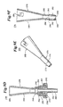
- Introducer 162 is shown in greater detail.
- Introducer 162 is a funnel-shaped device including a horn 172 and a neck 174.
- horn 172 and neck 174 are integrally formed as a singular body.
- Horn 172 is preferably a conically-shaped body having an outer wall 176.
- Outer wall 176 defines an interior space and includes a guide wire-receiving notch 180 formed near proximal end 182 of horn 172.
- Guide wire-receiving notch 180 is preferably J-shaped and includes an entry end 184 and a locking end 186. As shown in Fig. 8A, entry end 184 is open at proximal end 182 of horn 172. Conversely, locking end 186 is closed.
- Neck 174 is preferably tubular in shape, and includes a passage 188. Passage 188 is configured to be in fluid communication with interior space of horn 172.
- horn 172 and neck 174 are formed of a plastic material. Alternatively, any other semi-rigid or rigid, surgically-safe material may be used.
- catheter assembly 30 (Fig. 1) is inserted within sheath assembly 160. More particularly, distal end 46 (Fig. 1) of catheter shaft 38 (Fig. 1), including guide wire 36 (Fig. 1) is placed within horn 172 of introducer 162. The conical shape of horn 172 assists in directing distal end 46 of catheter shaft 38, including guide wire 36, into passage 188 of neck 174.
- Catheter shaft 38 continues forward within lumen (not shown) of sheath 166 until distal end 46 of catheter shaft 38 extends from distal end 170 of sheath 166.
- a proximal end of guide wire 36 (Fig. 1) is maintained within guide wire-receiving notch 180. More particularly, a portion of guide wire 36 is forced by an operator through entry end 184 of guide wire-receiving notch 180 and forced within locking end 186 thereof.
- locking end 186 preferably has a diameter slightly smaller than that of guide wire 36.
- guide wire 36 can easily be released from guide wire-receiving notch 180 by sliding guide wire 36 from locking end 186 and out of entry end 184.
- sheath assembly 160 functions in a manner highly similar to sheath assembly 100 and sheath assembly 110 previously described.
- Introducer 190 includes a horn 192, a neck 194 and a valve 196. Similar to previous embodiment, horn 192 and neck 194 are preferably integrally formed as a singular body.
- Horn 192 includes an outer wall 197 which defines a guide wire-receiving notch 198 and valve-receiving slots 200.
- Valve 196 includes a valve body 202 sized to fit within outer wall 197 of horn 192. Further, valve 196 includes ribs 204 extending from valve body 202. Ribs 204 are preferably sized to mate within valve-receiving slots 200 of horn 192.
- valve 196 is maintained within horn 192 via interaction of ribs 204 with valve-receiving slots 200.
- valve-receiving slots 200 are preferably positioned along horn 192 proximal neck 194.
- Valve 196 is preferably made of a rubber-type material.
- introducer 190 functions in a manner highly similar to introducer 162 (Figs. 8 and 8A) previously described. Additionally, however, valve 196 forms a seal about catheter shaft 38 (Fig. 1). Thus, upon insertion into a human body, valve 196 prevents bodily fluids, such as bile, from backing up through the sheath assembly. Additionally, valve 196 can provide for aspiration, if desired.
- introducer 206 is highly similar to introducer 190 (Fig. 9A) previously described.
- introducer 206 includes a horn 208, a neck 210 and a valve 212.
- Horn 208 is preferably integrally formed with neck 210 and includes an outer wall 214 defining a guide wire-receiving notch 216 and valve-receiving slots 218.
- valve 212 includes a valve body 220 and ribs 222. Ribs 222 are sized to mate within valve-receiving slots 218 of horn 208.
- valve-receiving slots 218 are positioned proximate a proximal end 224 of horn 208.
- Introducer 206 including valve 212, functions in a manner highly similar to introducer 190 (Fig. 9A) as previously described.
- Introducer 226 includes a horn 228, a neck 230 and an O-ring 232.
- Horn 228 and neck 230 are preferably formed as an integral body.
- Horn 228 preferably includes a guide wire-receiving notch (not shown) similar to that previously described and an interior slot 234.
- Interior slot 234 is preferably positioned proximate neck 230 and is sized to maintain O-ring 232.
- interior slot 234 can be formed in neck 230.
- O-ring 232 is preferably made of a rubber-type material. Further, O-ring 232 has an inner diameter slightly smaller than that of horn 228 and neck 230. Thus, during use, O-ring 232 forms a seal about catheter shaft 38 (Fig. 1), blocking passage of bodily fluids, such as bile, into horn 228.
- Introducer 236 is similar to a touhey-borst system and includes an upper horn section 238, a lower horn section 240 and a grommet 242.
- Upper horn section 238 includes an outer wall 244 defining a proximal end 246, a grommet-receiving flange 248 and a distal end 250.
- Proximal end 246 of horn section 238 preferably includes a guide wire-receiving notch (not shown) similar to that previously described.
- Distal end 250 is threaded and includes a passage 252 sized to receive a portion of lower horn section 240.
- Lower horn section 240 includes a body 254 defining a proximal end 256, an intermediate portion 258 and a distal end 260.
- An interior passage 266 is configured to communicate with passage 252 and extends from proximal end 256 to distal end 260.
- proximal end 256 includes a threaded slot 262 sized to threadably receive distal end 250 of upper horn section 238.
- Grommet 242 is preferably made of a rubber-type material and is sized to nest within grommet-receiving flange 248 of upper horn section 238 while abutting proximal end 256 of lower horn section 240.
- Introducer 236 is assembled by placing grommet 242 within grommet-receiving flange 248 of upper horn section 238. Distal end 250 of upper horn section 238 is then threadably secured to proximal end 258 of lower horn section 240. As upper horn section 238 is threadably secured to lower horn section 240, proximal end 256 of lower horn section 240 compresses grommet 242 within grommet-receiving flange 248 of upper horn section 238.
- introducer 236 functions in a manner highly similar to that previously described. In this regard, grommet 242 forms a seal about catheter shaft 38 (Fig. 1). Further, aspiration can be achieved, if desired, by loosening lower horn section 240 relative to upper horn section 238.
- Introducer 266 includes a horn 268, a neck 270 and a valve 272.
- horn 268, neck 270 and valve 272 are integrally formed as a singular body.
- valve 272 is formed while molding horn 268 and neck 270 by imparting a controlled flash at distal end 274 of neck 270.
- valve 272 forms a seal about catheter shaft 38 (Fig. 1), thereby preventing back flow of bodily fluids, such as bile, into horn 268.
- Introducer 276 includes a horn 278, a neck 280 and a valve 282.
- Horn 278 and neck 280 are preferably integrally formed as a singular body.
- horn 278 and neck 280 are defined by an outer wall 284.
- Outer wall 284 forms a guide wire-receiving notch 286 and an exterior slot 288.
- Guide wire-receiving notch 286 is similar to that previously described.
- Exterior slot 288 is positioned along neck 280 and is sized to maintain a portion of valve 282. Alternatively, exterior slot 288 can be positioned along horn 278.
- Valve 282 is preferably a rubber-type sock defined by an upper rib 290, a side wall 292 and a shoulder 294.
- Upper rib 290 is preferably sized to mount within exterior slot 288 of neck 280.
- Side wall 292 is preferably flexible so as to stretch along neck 280.
- shoulder 294 is preferably configured to abut a distal end 298 of neck 280. With this configuration, valve 282 is placed over distal end 298 of neck 280 such that shoulder 294 contacts distal end 298. Due to the preferred flexible characteristic of valve 282, side wall 292 is stretched until upper rib 290 nests within exterior slot 288 of neck 280.
- valve 282 prevents undesired back flow of bodily fluids, such as bile.
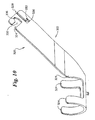
- Fig. 10 is a perspective view of a locking device according to the invention for use with an endoscope having a side instrument port.
- the locking device is generally shown at 320 and includes a body member 322.
- the body member 322 includes one or more hook members 324 for attaching the locking device to a shaft of an endoscope or the like (see Fig. 11).
- the body member 322 includes a securing mechanism for securing a guide wire or catheter to the locking device.
- the hook members 324 may be provided in pairs, as shown in Fig. 10, or offset from one another, as shown in Fig. 13. In either case, the hook members 324 are adapted to clip and secure the locking device to the shaft of an endoscope or the like.
- the securing mechanism preferably includes one or more openings provided in the body member 322.
- the body member 322 includes a guide wire opening 326 and a catheter opening 332.
- the guide wire opening 326 is similar to the guide wire-receiving notch 180 of Fig. 8A.
- the guide wire opening 326 is preferably J-shaped, and preferably includes an entry slot 328 and a locking slot 330.
- the catheter opening 332 is boot shaped, and also preferably includes an entry slot 334 and a locking slot 336.
- the entry slot 328 of the guide wire opening 326 is dimensioned to be larger than the diameter of a guide wire.
- the locking slot 330 of the guide wire opening 326 is dimensioned to be somewhat smaller than the diameter of a guide wire. Accordingly, a guide wire can be secured to the body member 322 by inserting a portion of the guide wire through the entry slot 328 of the guide wire opening 326 and into the locking slot 330. The locking slot 330 frictionally secures the guide wire relative to the body member 322.
- the entry slot 334 of the catheter opening 332 is dimensioned to be larger than the diameter of a catheter.
- the locking slot 336 of the catheter opening 332 is dimensioned to be somewhat smaller than the diameter of a catheter. Accordingly, a catheter can be secured to the body member 322 by inserting a portion of the catheter through the entry end 334 of the catheter opening 332 and into the locking slot 336. The locking slot 336 frictionally secures the catheter relative to the body member 322.
- Fig. 11 is a partial side view of a locking device positioned on an endoscope with an angled side port extending therefrom.
- the endoscope is generally shown at 350, and includes a main shaft 352 with a lumen extending therethrough.
- a side port 356 extends laterally away from the main shaft 352 at an angle.
- the side port 356 provides access to the lumen of the main shaft 352. Accordingly, a guide wire and/or catheter may access the lumen of the main shaft 352 via the side port 356.
- the side port 356 preferably includes a side port opening 354 which is laterally spaced from the main shaft 352 due to the angular displacement between the main shaft 352 and the side port 356.
- the side port opening 354 is in fluid communication with the lumen of the main shaft 352 via a connection tube 355.
- the connection tube 355 intersects a side wall of the main shaft 352 at an angle, as shown.
- a locking device having a body member 360 is shown clipped onto the main shaft 352 of the endoscope.
- the body member 360 includes a number of hook members 358 for attaching the locking device to the main shaft 352. Two hook members are visible in Fig. 11.
- the hook members 358 are similar to the hook members 324 described above with respect to Fig. 10.
- the body member 360 extends away from the hook members 358 and generally parallel to the side port 356. In Fig. 11, the body member is obscured by the main shaft 352 and side port 356. The body member 360 extends upward past the side port opening 354, wherein a securing mechanism is provided.
- the securing mechanism is a J-shaped guide wire opening 362.
- a guide wire is advanced into the body via the endoscope.
- the proximal end thereof may be moved to a first position 364, which is in the entry slot of the guide wire opening 362.
- the guide wire may be moved to a second position 366, which is in the locking slot of the guide wire opening 362.
- the locking slot of the guide wire opening 362 frictionally secures the guide wire relative to the body member 360.
- Fig. 12 is a partial side view detailing the locking device ofFig. 11, with an additional oversized catheter opening shown.
- the side port of the endoscope is shown at 356, and the body member of the locking device is shown at 360.
- a guide wire opening 362 Positioned proximate the side port opening 354 is a guide wire opening 362 and an oversized catheter opening 370.
- the guide wire opening is J-shaped and includes an entry slot and a locking slot.
- the guide wire may be moved to the first position 364, which is in the entry slot of the guide wire opening 362.
- the guide wire may be moved to the second position 366, which is in the locking slot of the guide wire opening 362.
- the locking slot of the guide wire opening 362 frictionally secures the guide wire relative to the body member 360.
- the oversized catheter opening 370 is sized to restrict lateral movement of the catheter 372 but not longitudinal movement of the catheter 372.
- Providing a guide wire opening that can secure the guide wire relative to the body member, and an oversized catheter opening for only restricting lateral movement of the catheter 372 may be particularly useful in performing a catheter exchange procedure.
- the guide wire opening may maintain the position of the guide wire.
- the oversized catheter opening 370 may separate the catheter from the guide wire, as the catheter is withdrawn.
- the first and second catheters should be single-operator exchange type catheters to provide access to the guide wire during the exchange.
- Fig. 13 is a perspective view of another locking device.
- the embodiment shown in Fig. 13 is similar to the embodiment shown in Fig. 10, but the hook members are laterally offset rather than aligned.
- hook member 380 is laterally offset from hook member 382 by a distance "D".
- This configuration is another example of an attachment mechanism for attaching the body member to a catheter shaft.
- Fig. 14 is a perspective view of yet another locking device.
- the locking device is generally shown at 400, and includes a body member 401 having an attachment mechanism 402 at one end and a securing mechanism 404 at the other.
- the attachment mechanism 402 includes a first hook member 406 and a second hook member 408.
- the first hook member 406 and the second hook member 408 are adapted to extend around a substantial portion of the shaft of an endoscope or the like. Thus, the first hook member 406 and the second hook member 408 may clip the body member 401 to the desired shaft.
- the securing mechanism 404 includes a J-shaped guide wire opening 410 and a flap-type catheter opening 412.
- the J-shaped guide wire opening 410 operates similar to that described above.
- the flap-type catheter opening 412 has a flap 414 formed by cutting the catheter opening 412 from the body member 401.
- the flap 414 is preferably curved to form a channel 416, wherein the end portion 418 of the channel 416 loops back to near the surface of the body member 401.
- a catheter or guide wire may be selectively provided in the channel 416, which may bend the flap away from the body member 401. Accordingly, the flap 412 may provide force between the guide wire or catheter and the body member 401 to effectively secured the guide wire or catheter to the body member 401.
- Fig. 15 is a partial side view of yet another locking device 500.
- the locking device 500 is positioned between a side port 504 and a main shaft 506 of an endoscope 502.
- the locking device includes a body member 510 that is attached to the main shaft 506 using a strap 512.
- the strap 512 extends around the entire circumference of the main shaft 506.
- the body member 510 may include a guide wire opening 514 and one or more catheter openings 516, as shown.
Landscapes
- Health & Medical Sciences (AREA)
- Life Sciences & Earth Sciences (AREA)
- Biophysics (AREA)
- Pulmonology (AREA)
- Engineering & Computer Science (AREA)
- Anesthesiology (AREA)
- Biomedical Technology (AREA)
- Heart & Thoracic Surgery (AREA)
- Hematology (AREA)
- Animal Behavior & Ethology (AREA)
- General Health & Medical Sciences (AREA)
- Public Health (AREA)
- Veterinary Medicine (AREA)
- Media Introduction/Drainage Providing Device (AREA)
- Endoscopes (AREA)
Description
Claims (16)
- A locking device (320; 400; 500) for use with an elongated tube, the elongated tube having a shaft (352; 506) with a lumen extending therethrough and an access port (356; 504) for accessing the lumen, the lumen adapted for receiving an elongated member with an outside portion of the elongated member extending outside of the lumen via the access port (356; 504) and an inside portion of the elongated member extending inside the lumen, wherein the shaft (352; 506) has a proximal end and distal end, the access port (356; 504) accessing the lumen of the shaft (352; 506) through a side wall of the shaft at a location distal of the proximal end of the shaft, an access port opening (354) being axially spaced from the shaft (352; 506) and in fluid communication with the lumen of the shaft via a connection tube (355), wherein the connection tube (355) extends away from the shaft (352; 506) at an angle, the locking device (320; 400; 500) comprising:a substantially rigid body member (322; 360; 401; 510) having a wall;attachment means (324; 358; 380, 382; 406, 408; 512) for operatively attaching the body member (322; 360; 401; 510) to the elongated tube, andsecuring means for selectively securing at least part of the outside portion of the elongated member to the body member (322; 360; 401; 510); wherein the securing means includes an opening (326, 332; 362; 370; 410, 412; 514, 516) in the wall of the body member (322; 360; 401; 510) for selectively receiving the elongated member; andthe rigid body member (322; 360; 401; 510) extends from the attachment means (324; 358; 380, 382; 406, 408; 512) to the securing means in a shape and size corresponding to the connection tube such that, when the locking device is attached via the attachment means to the shalf (352; 506) at a location near the access port (356; 504), the securing means is located near the access port with the body member extending along side the connection tube.
- The locking device of claim 1 wherein the elongated member is a guide wire.
- The locking device of claim 2 wherein the opening (326, 332; 362; 370; 410; 514, 516) is J-shaped with a locking slot (330).
- The locking device of claim 3, wherein the locking slot (330) has a reduced dimension relative to the outside portion of the guide wire so that the guide wire can be selectively frictionally fit in the locking slot.
- The locking device of claim 1 wherein the elongated member is a catheter (372).
- The locking device of claim 5 wherein the opening is boot shaped having a locking slot.
- The locking device of claim 6, wherein the locking slot has a reduced dimension relative to the outside portion of the catheter (372) so that the catheter can be selectively frictionally fit in the locking slot.
- The locking device of claim 5 wherein the catheter (372) is a single-operator-exchange type catheter.
- The locking device of claim 1 wherein the elongated tube is an endoscope (350; 502)
- The locking device of claim 1 wherein the elongated tube is a guide catheter.
- The locking device of claim 1 wherein the attachment means (324; 358; 380, 382; 406, 408; 512) comprises at least one hook member that extends at least half-way around the circumference of the shaft (352; 506).
- The locking device of claim 11 wherein the body member (322; 360; 401; 510) extends from the at least one hook member to a position proximate the access port opening (354), and the securing means is positioned proximate the access port opening (354).
- The locking device of claim 1 further comprising another securing means which includes another opening (326, 332; 362; 370; 410, 412, 514, 516) in the body member (322; 360; 401; 510) for selectively receiving another elongated member.
- A method comprising the steps of:providing an elongated tube with a lumen extending therethrough and an access port (356) for accessing the lumen;inserting an elongated member at least partially into the lumen via the access port (356) such that the elongated member has an outside portion that extends outside of the lumen and an inside portion that extends inside the lumen;providing a locking device (320; 400; 500) sized and shaped for operative attachment to the elongated tube, the locking device having a wall with an opening (326, 352; 362; 370; 410, 412; 514, 516) therein wherein the opening is positioned proximate the access port (356; 504), the opening having a locking slot (330) that has a reduced dimension relative to the outside portion of the elongated member;attaching the locking device to the elongated member near the access port; andselectively securing the elongated member to the locking device by positioning at least part of the outside portion of the elongated member in the locking slot of the opening.
- A method according to claim 14 wherein the elongated member is a guide wire.
- A method according to claim 14 wherein the elongated member is a catheter (372).
Applications Claiming Priority (3)
| Application Number | Priority Date | Filing Date | Title |
|---|---|---|---|
| US80520 | 1998-05-18 | ||
| US09/080,520 US6096009A (en) | 1996-09-13 | 1998-05-18 | Guidewire and catheter locking device and method |
| PCT/US1999/004208 WO1999059664A1 (en) | 1998-05-18 | 1999-02-23 | Guidewire and catheter locking device and method |
Publications (2)
| Publication Number | Publication Date |
|---|---|
| EP1079883A1 EP1079883A1 (en) | 2001-03-07 |
| EP1079883B1 true EP1079883B1 (en) | 2005-07-13 |
Family
ID=22157914
Family Applications (1)
| Application Number | Title | Priority Date | Filing Date |
|---|---|---|---|
| EP99908507A Expired - Lifetime EP1079883B1 (en) | 1998-05-18 | 1999-02-23 | Guidewire and catheter locking device and method |
Country Status (7)
| Country | Link |
|---|---|
| US (5) | US6096009A (en) |
| EP (1) | EP1079883B1 (en) |
| JP (1) | JP3816749B2 (en) |
| AU (1) | AU759421B2 (en) |
| CA (1) | CA2332551C (en) |
| DE (1) | DE69926124T2 (en) |
| WO (1) | WO1999059664A1 (en) |
Cited By (2)
| Publication number | Priority date | Publication date | Assignee | Title |
|---|---|---|---|---|
| WO2011110152A1 (en) | 2010-03-12 | 2011-09-15 | Medi-Globe Gmbh | Guide wire holder for receiving and securing a medical guide wire and for mounting on a medical appliance, in particular on an endoscope |
| CN110916769A (en) * | 2019-12-04 | 2020-03-27 | 董军强 | Improvement type pulmonary nodule puncture pilot pin external member |
Families Citing this family (163)
| Publication number | Priority date | Publication date | Assignee | Title |
|---|---|---|---|---|
| US6582401B1 (en) | 1996-09-13 | 2003-06-24 | Scimed Life Sytems, Inc. | Multi-size convertible catheter |
| US5921971A (en) | 1996-09-13 | 1999-07-13 | Boston Scientific Corporation | Single operator exchange biliary catheter |
| US6606515B1 (en) * | 1996-09-13 | 2003-08-12 | Scimed Life Systems, Inc. | Guide wire insertion and re-insertion tools and methods of use |
| US6346093B1 (en) | 1996-09-13 | 2002-02-12 | Scimed Life Systems, Inc. | Single operator exchange biliary catheter with common distal lumen |
| US6096009A (en) | 1996-09-13 | 2000-08-01 | Boston Scientific Corporation | Guidewire and catheter locking device and method |
| US6520951B1 (en) * | 1996-09-13 | 2003-02-18 | Scimed Life Systems, Inc. | Rapid exchange catheter with detachable hood |
| US6796976B1 (en) * | 1998-03-06 | 2004-09-28 | Scimed Life Systems, Inc. | Establishing access to the body |
| US6117140A (en) | 1998-06-26 | 2000-09-12 | Scimed Life Systems, Inc. | Stent delivery device |
| US7637905B2 (en) | 2003-01-15 | 2009-12-29 | Usgi Medical, Inc. | Endoluminal tool deployment system |
| US7955340B2 (en) | 1999-06-25 | 2011-06-07 | Usgi Medical, Inc. | Apparatus and methods for forming and securing gastrointestinal tissue folds |
| US7811250B1 (en) * | 2000-02-04 | 2010-10-12 | Boston Scientific Scimed, Inc. | Fluid injectable single operator exchange catheters and methods of use |
| US6858005B2 (en) | 2000-04-03 | 2005-02-22 | Neo Guide Systems, Inc. | Tendon-driven endoscope and methods of insertion |
| US6610007B2 (en) | 2000-04-03 | 2003-08-26 | Neoguide Systems, Inc. | Steerable segmented endoscope and method of insertion |
| US6468203B2 (en) | 2000-04-03 | 2002-10-22 | Neoguide Systems, Inc. | Steerable endoscope and improved method of insertion |
| US6837846B2 (en) * | 2000-04-03 | 2005-01-04 | Neo Guide Systems, Inc. | Endoscope having a guide tube |
| US6974411B2 (en) * | 2000-04-03 | 2005-12-13 | Neoguide Systems, Inc. | Endoscope with single step guiding apparatus |
| US8888688B2 (en) | 2000-04-03 | 2014-11-18 | Intuitive Surgical Operations, Inc. | Connector device for a controllable instrument |
| US8517923B2 (en) | 2000-04-03 | 2013-08-27 | Intuitive Surgical Operations, Inc. | Apparatus and methods for facilitating treatment of tissue via improved delivery of energy based and non-energy based modalities |
| US6984203B2 (en) * | 2000-04-03 | 2006-01-10 | Neoguide Systems, Inc. | Endoscope with adjacently positioned guiding apparatus |
| JP2001340468A (en) * | 2000-05-30 | 2001-12-11 | Olympus Optical Co Ltd | Medical guide wire |
| US6764484B2 (en) * | 2001-03-30 | 2004-07-20 | Scimed Life Systems, Inc. | C-channel to o-channel converter for a single operator exchange biliary catheter |
| US20050021123A1 (en) | 2001-04-30 | 2005-01-27 | Jurgen Dorn | Variable speed self-expanding stent delivery system and luer locking connector |
| US6746466B2 (en) | 2001-05-22 | 2004-06-08 | Scimed Life Systems, Inc. | Method and apparatus for managing multiple guidewires |
| WO2003011356A2 (en) * | 2001-07-27 | 2003-02-13 | Becton, Dickinson And Company | Luer connector assembly |
| US6786886B2 (en) * | 2001-08-03 | 2004-09-07 | Scimed Life Systems, Inc. | Method for stabilizing balloon during dilation |
| US6827718B2 (en) * | 2001-08-14 | 2004-12-07 | Scimed Life Systems, Inc. | Method of and apparatus for positioning and maintaining the position of endoscopic instruments |
| EP1469781B1 (en) | 2002-01-09 | 2016-06-29 | Intuitive Surgical Operations, Inc. | Apparatus for endoscopic colectomy |
| US20030187389A1 (en) * | 2002-03-29 | 2003-10-02 | Scimed Life Systems, Inc. | Center support for steerable electrophysiology catheter |
| US6800065B2 (en) | 2002-04-04 | 2004-10-05 | Medtronic Ave, Inc. | Catheter and guide wire exchange system |
| US7326224B2 (en) * | 2002-06-11 | 2008-02-05 | Boston Scientific Scimed, Inc. | Shaft and wire lock |
| US7041052B2 (en) | 2002-06-13 | 2006-05-09 | Usgi Medical Inc. | Shape lockable apparatus and method for advancing an instrument through unsupported anatomy |
| US6837847B2 (en) | 2002-06-13 | 2005-01-04 | Usgi Medical, Inc. | Shape lockable apparatus and method for advancing an instrument through unsupported anatomy |
| US6851424B2 (en) * | 2002-08-08 | 2005-02-08 | Scimed Life Systems, Inc. | Mouthguard having device securing tab |
| US7172577B2 (en) * | 2002-08-09 | 2007-02-06 | Boston Scientific Scimed, Inc. | Guidewire locking device and method |
| US6966890B2 (en) * | 2002-08-23 | 2005-11-22 | Medtronic Vascular, Inc. | Convertible balloon catheter and manufacture thereof |
| US20040059369A1 (en) * | 2002-09-20 | 2004-03-25 | Niall Duffy | Catheter and guide wire exchange system |
| US7037293B2 (en) * | 2002-11-15 | 2006-05-02 | Boston Scientific Scimed, Inc. | Rapid exchange catheter with depressable channel |
| US20040147908A1 (en) * | 2003-01-24 | 2004-07-29 | Niall Duffy | Accessory for over the wire catheter with short wire capability |
| US6893393B2 (en) * | 2003-02-19 | 2005-05-17 | Boston Scientific Scimed., Inc. | Guidewire locking device and method |
| US20040176790A1 (en) * | 2003-03-03 | 2004-09-09 | Medtronic Ave, Inc. | Single lumen catheter shaft for a balloon catheter |
| US8882657B2 (en) | 2003-03-07 | 2014-11-11 | Intuitive Surgical Operations, Inc. | Instrument having radio frequency identification systems and methods for use |
| US20040199052A1 (en) | 2003-04-01 | 2004-10-07 | Scimed Life Systems, Inc. | Endoscopic imaging system |
| US7273486B2 (en) * | 2003-04-11 | 2007-09-25 | Medtronic Vascular, Inc. | Catheter with a convertible proximal catheter shaft |
| US7208001B2 (en) * | 2003-04-24 | 2007-04-24 | Medtronic Vascular, Inc. | Catheter with detached proximal inflation and guidewire shafts |
| US9101383B1 (en) | 2003-04-25 | 2015-08-11 | Annex Medical, Inc. | Medical retrieval device |
| US20040254528A1 (en) * | 2003-06-12 | 2004-12-16 | Adams Daniel O. | Catheter with removable wire lumen segment |
| US20040260329A1 (en) * | 2003-06-19 | 2004-12-23 | Richard Gribbons | Catheter and guide wire exchange system with decoupled guide member |
| DE602004017476D1 (en) * | 2003-07-31 | 2008-12-11 | Wilson Cook Medical Inc | Guidewire holder |
| US8206320B2 (en) * | 2003-07-31 | 2012-06-26 | Cook Medical Technologies Llc | System and method for introducing multiple medical devices |
| US7276045B2 (en) * | 2003-11-24 | 2007-10-02 | Medtronic Vascular, Inc. | Apparatus and method for wire exchange |
| US7703459B2 (en) | 2004-03-09 | 2010-04-27 | Usgi Medical, Inc. | Apparatus and methods for mapping out endoluminal gastrointestinal surgery |
| ES2409160T3 (en) * | 2004-03-23 | 2013-06-25 | Boston Scientific Limited | Live View System |
| US7922654B2 (en) | 2004-08-09 | 2011-04-12 | Boston Scientific Scimed, Inc. | Fiber optic imaging catheter |
| US11832793B2 (en) | 2004-03-23 | 2023-12-05 | Boston Scientific Scimed, Inc. | Vivo visualization system |
| US7217246B1 (en) | 2004-06-17 | 2007-05-15 | Biomet Sports Medicine, Inc. | Method and apparatus for retaining a fixation pin to a cannula |
| US7828751B2 (en) * | 2004-06-17 | 2010-11-09 | Biomet Sports Medicine, Llc | Method and apparatus for retaining a fixation pin to a cannula |
| US20060047265A1 (en) * | 2004-08-25 | 2006-03-02 | Medtronic Vascular, Inc. | Multi-exchange catheter guide member with improved seal |
| US8414527B2 (en) | 2004-09-21 | 2013-04-09 | Boston Scientific Scimed, Inc. | Rapid exchange catheters having a sealed guidewire lumen and methods of making the same |
| JP4901087B2 (en) * | 2004-09-24 | 2012-03-21 | オリンパス株式会社 | Stent introduction member, stent delivery catheter, and endoscope treatment system |
| JP2006204476A (en) * | 2005-01-27 | 2006-08-10 | Olympus Corp | Operative appliance for endoscope |
| US8480629B2 (en) | 2005-01-28 | 2013-07-09 | Boston Scientific Scimed, Inc. | Universal utility board for use with medical devices and methods of use |
| EP1853341A2 (en) * | 2005-02-10 | 2007-11-14 | Wilson-Cook Medical Inc. | Wire guide holder with wire guide deflector |
| WO2006089178A2 (en) * | 2005-02-18 | 2006-08-24 | Ev3 Inc. | Rapid exchange catheters and embolic protection devices |
| JP2006246982A (en) * | 2005-03-09 | 2006-09-21 | Pentax Corp | Filling for endoscope |
| US20060224115A1 (en) * | 2005-03-30 | 2006-10-05 | Boston Scientific Scimed, Inc. | Balloon catheter with expandable wire lumen |
| US8523879B1 (en) | 2005-03-31 | 2013-09-03 | Stuart J. Lind | Stone retriever for flexible endoscopes having small diameter working channels |
| EP2179709B1 (en) | 2005-08-17 | 2011-10-05 | C. R. Bard, Inc. | Variable speed stent delivery system |
| US20070049801A1 (en) * | 2005-08-24 | 2007-03-01 | Lamport Ronald B | Endoscope accessory |
| US20070118079A1 (en) * | 2005-11-21 | 2007-05-24 | Moberg John R | Medical devices and related systems and methods |
| EP1956962B1 (en) | 2005-11-22 | 2020-09-16 | Intuitive Surgical Operations, Inc. | System for determining the shape of a bendable instrument |
| US8083879B2 (en) | 2005-11-23 | 2011-12-27 | Intuitive Surgical Operations, Inc. | Non-metallic, multi-strand control cable for steerable instruments |
| CA2936205C (en) | 2006-01-13 | 2018-08-21 | C.R. Bard, Inc. | Stent delivery system |
| US11026822B2 (en) | 2006-01-13 | 2021-06-08 | C. R. Bard, Inc. | Stent delivery system |
| JP4920279B2 (en) * | 2006-03-29 | 2012-04-18 | テルモ株式会社 | Endoscope |
| US8926499B2 (en) * | 2006-04-17 | 2015-01-06 | Boston Scientific Scimed, Inc. | Catheter for use with an endoscope |
| US20070244356A1 (en) * | 2006-04-17 | 2007-10-18 | Boston Scientific Scimed, Inc. | Elongate medical devices having an improved distal profile for use with an endoscope |
| US8992470B2 (en) | 2006-05-19 | 2015-03-31 | Boston Scientific Scimed, Inc. | Control mechanism for steerable medical device |
| US8568299B2 (en) | 2006-05-19 | 2013-10-29 | Intuitive Surgical Operations, Inc. | Methods and apparatus for displaying three-dimensional orientation of a steerable distal tip of an endoscope |
| US9149173B2 (en) * | 2006-06-20 | 2015-10-06 | Boston Scientific Scimed, Inc. | Medical device for use in endoscopic procedure |
| US9844649B2 (en) * | 2006-07-07 | 2017-12-19 | Cook Medical Technologies Llc | Telescopic wire guide |
| GB0615658D0 (en) | 2006-08-07 | 2006-09-13 | Angiomed Ag | Hand-held actuator device |
| DE602007005013D1 (en) * | 2006-09-08 | 2010-04-08 | Pamgene Bv | TEST PROCEDURE FOR NUCLEAR RECEPTORS |
| US9107736B2 (en) * | 2006-12-06 | 2015-08-18 | Abbott Cardiovascular Systems Inc. | Highly trackable balloon catheter system and method for collapsing an expanded medical device |
| WO2008085712A1 (en) | 2007-01-03 | 2008-07-17 | Boston Scientific Limited | Method and apparatus for biliary access and stone retrieval |
| WO2008092029A2 (en) | 2007-01-24 | 2008-07-31 | Access Scientific, Inc. | Access device |
| US8480570B2 (en) | 2007-02-12 | 2013-07-09 | Boston Scientific Scimed, Inc. | Endoscope cap |
| US20090062769A1 (en) * | 2007-04-13 | 2009-03-05 | Boston Scientific Scimed, Inc. | Rapid exchange catheter converter |
| US8105286B2 (en) | 2007-04-18 | 2012-01-31 | Access Scientific, Inc. | Access device |
| US20100256446A1 (en) * | 2007-05-11 | 2010-10-07 | Board Of Regents, The University Of Texas System | Medical scope carrier and scope as system and method |
| GB0713497D0 (en) | 2007-07-11 | 2007-08-22 | Angiomed Ag | Device for catheter sheath retraction |
| WO2009041968A1 (en) * | 2007-09-27 | 2009-04-02 | Cryocath Technologies Inc. | Accessory sleeve for a medical device |
| US9220398B2 (en) | 2007-10-11 | 2015-12-29 | Intuitive Surgical Operations, Inc. | System for managing Bowden cables in articulating instruments |
| US8187172B2 (en) | 2007-10-22 | 2012-05-29 | Cook Medical Technologies Llc | Endoscope cap with aperture |
| US20090299352A1 (en) * | 2007-12-21 | 2009-12-03 | Boston Scientific Scimed, Inc. | Steerable laser-energy delivery device |
| US8137336B2 (en) | 2008-06-27 | 2012-03-20 | Boston Scientific Scimed, Inc. | Steerable medical device |
| EP2249690B1 (en) | 2008-02-06 | 2021-09-29 | Intuitive Surgical Operations, Inc. | A segmented instrument having braking capabilities |
| US8343041B2 (en) | 2008-05-19 | 2013-01-01 | Boston Scientific Scimed, Inc. | Integrated locking device with passive sealing |
| US8388521B2 (en) | 2008-05-19 | 2013-03-05 | Boston Scientific Scimed, Inc. | Integrated locking device with active sealing |
| US8182418B2 (en) | 2008-02-25 | 2012-05-22 | Intuitive Surgical Operations, Inc. | Systems and methods for articulating an elongate body |
| US8979828B2 (en) | 2008-07-21 | 2015-03-17 | The Spectranetics Corporation | Tapered liquid light guide |
| US9421065B2 (en) | 2008-04-02 | 2016-08-23 | The Spectranetics Corporation | Liquid light-guide catheter with optically diverging tip |
| US9782566B1 (en) * | 2008-05-01 | 2017-10-10 | Annex Medical, Inc. | Bend limiting access sheath |
| US20090287111A1 (en) * | 2008-05-16 | 2009-11-19 | Us Endoscopy Group, Inc. | Endoscope collection vessel |
| WO2009142208A1 (en) * | 2008-05-22 | 2009-11-26 | テルモ株式会社 | Catheter retaining tool |
| JP5484699B2 (en) * | 2008-09-08 | 2014-05-07 | オリンパスメディカルシステムズ株式会社 | Endoscope insertion aid and endoscope apparatus |
| JP5052553B2 (en) * | 2009-03-19 | 2012-10-17 | オリンパス株式会社 | Treatment endoscope |
| US9023069B2 (en) | 2009-05-18 | 2015-05-05 | Covidien Lp | Attachable clamp for use with surgical instruments |
| AU2011213558A1 (en) | 2010-02-08 | 2012-09-27 | Access Scientific, Inc. | Access device |
| US8641717B2 (en) * | 2010-07-01 | 2014-02-04 | DePuy Synthes Products, LLC | Guidewire insertion methods and devices |
| JP2012075800A (en) * | 2010-10-05 | 2012-04-19 | Inter Noba Kk | Catheter |
| GB201017834D0 (en) | 2010-10-21 | 2010-12-01 | Angiomed Ag | System to deliver a bodily implant |
| WO2012141757A1 (en) * | 2010-12-29 | 2012-10-18 | Neochord, Inc. | Exchangeable system for minimally invasive beating heart repair of heart valve leaflets |
| EP2696929A1 (en) | 2011-04-11 | 2014-02-19 | The Spectranetics Corporation | Needle and guidewire holder |
| US20130035757A1 (en) | 2011-06-01 | 2013-02-07 | John Zentgraf | Minimally invasive repair of heart valve leaflets |
| WO2013003450A1 (en) | 2011-06-27 | 2013-01-03 | Boston Scientific Scimed, Inc. | Stent delivery systems and methods for making and using stent delivery systems |
| US8676301B2 (en) | 2011-07-14 | 2014-03-18 | Med Works Limited | Guide wire incorporating a handle |
| WO2013019550A2 (en) * | 2011-07-29 | 2013-02-07 | Boston Scientific Scimed, Inc. | Rapid exchange stent delivery system |
| US9597152B2 (en) | 2011-09-10 | 2017-03-21 | Cook Medical Technologies Llc | Control handles for medical devices |
| US10349958B2 (en) | 2012-03-27 | 2019-07-16 | Cook Medical Technologies Llc | Lithotripsy probes and methods for performing lithotripsy |
| EP2925401A4 (en) | 2012-10-02 | 2016-11-16 | Queens Medical Ct | Vascular access systems having a guidewire anti-migration feature |
| US20140194849A1 (en) * | 2013-01-07 | 2014-07-10 | Cook Medical Technologies Llc | Removable clip for catheter |
| US9867620B2 (en) * | 2013-03-14 | 2018-01-16 | Covidien Lp | Articulation joint for apparatus for endoscopic procedures |
| WO2014151615A2 (en) | 2013-03-15 | 2014-09-25 | Boston Scientific Scimed, Inc. | Stent delivery system |
| US9289247B2 (en) | 2013-03-15 | 2016-03-22 | Kyphon SÀRL | Surgical tool holder |
| US9566087B2 (en) | 2013-03-15 | 2017-02-14 | Access Scientific, Llc | Vascular access device |
| US9433427B2 (en) | 2014-04-08 | 2016-09-06 | Incuvate, Llc | Systems and methods for management of thrombosis |
| WO2016059908A1 (en) * | 2014-10-17 | 2016-04-21 | オリンパス株式会社 | Holding mechanism and insertion device |
| JP5977910B1 (en) * | 2014-10-17 | 2016-08-24 | オリンパス株式会社 | Holding mechanism and insertion device |
| EP3209192A4 (en) * | 2014-10-20 | 2019-01-16 | Research Development International Corporation | Steerable micro-endoscope |
| US20160166821A1 (en) * | 2014-12-15 | 2016-06-16 | Intermountain Invention Management, Llc | Devices for restraining movement of elongated medical implements and related systems and methods |
| US11027099B2 (en) | 2015-04-30 | 2021-06-08 | Smiths Medical Asd, Inc. | Vascular access device |
| CN107624056B (en) | 2015-06-30 | 2020-06-09 | 恩朵罗杰克斯股份有限公司 | Locking assembly and related system and method |
| WO2017019564A1 (en) * | 2015-07-24 | 2017-02-02 | Route 92 Medical, Inc. | Methods of intracerebral implant delivery |
| US10151336B2 (en) * | 2015-08-03 | 2018-12-11 | Mobility Holdings, Limited | Clamp device with resilience |
| US10688286B2 (en) * | 2015-09-17 | 2020-06-23 | Secure Surgical Inc | Devices and methods for securing surgical guide wires |
| US10765517B2 (en) | 2015-10-01 | 2020-09-08 | Neochord, Inc. | Ringless web for repair of heart valves |
| US20170100142A1 (en) | 2015-10-09 | 2017-04-13 | Incuvate, Llc | Systems and methods for management of thrombosis |
| US10252035B2 (en) | 2015-12-07 | 2019-04-09 | Cook Medical Techonologies Llc | Rotatable control handles for medical devices and methods of using rotatable control handles |
| WO2017183366A1 (en) * | 2016-04-18 | 2017-10-26 | オリンパス株式会社 | Instrument insertion aid |
| WO2017192520A1 (en) | 2016-05-03 | 2017-11-09 | Cook Medical Technologies Llc | Wire lock assembly |
| US11547415B2 (en) | 2016-07-22 | 2023-01-10 | Route 92 Medical, Inc. | Endovascular interventions in neurovascular anatomy |
| US11439476B2 (en) * | 2016-08-30 | 2022-09-13 | Gyrus Acmi, Inc. | Medical device handle lock |
| WO2018071651A1 (en) * | 2016-10-12 | 2018-04-19 | Kenneth Smith | Device and method for locking and tagging a medical tube |
| US10213306B2 (en) | 2017-03-31 | 2019-02-26 | Neochord, Inc. | Minimally invasive heart valve repair in a beating heart |
| KR101905318B1 (en) * | 2017-04-14 | 2018-10-05 | 김주현 | Surrical apparatus for performing microscope spine surgery of minimum invasion |
| US10674894B2 (en) * | 2017-05-03 | 2020-06-09 | Hoya Corporation | Systems and methods for device exchange in an endoscopic procedure |
| EP3664684B1 (en) | 2017-08-11 | 2022-11-30 | Boston Scientific Scimed, Inc. | Biopsy cap for use with endoscope |
| US10569059B2 (en) | 2018-03-01 | 2020-02-25 | Asspv, Llc | Guidewire retention device |
| WO2019183626A1 (en) | 2018-03-23 | 2019-09-26 | Neochord, Inc. | Device for suture attachment for minimally invasive heart valve repair |
| US11253360B2 (en) | 2018-05-09 | 2022-02-22 | Neochord, Inc. | Low profile tissue anchor for minimally invasive heart valve repair |
| US11173030B2 (en) | 2018-05-09 | 2021-11-16 | Neochord, Inc. | Suture length adjustment for minimally invasive heart valve repair |
| IT201800006767A1 (en) * | 2018-06-28 | 2019-12-28 | VALVE FOR ENDOSCOPE | |
| KR102108847B1 (en) * | 2018-07-20 | 2020-05-11 | 김주현 | Apparaturs for removing osteophyte |
| CN113194854A (en) | 2018-09-07 | 2021-07-30 | 尼奥绰德有限公司 | Suture attachment device for minimally invasive heart valve repair |
| US11666206B2 (en) | 2018-10-16 | 2023-06-06 | Olympus Corporation | Guidewire locking device |
| US11812932B2 (en) | 2018-10-16 | 2023-11-14 | Gyrus Acmi, Inc. | Guidewire locking device |
| US11672958B2 (en) | 2018-10-16 | 2023-06-13 | Olympus Corporation | Guidewire locking device |
| EP4215102A1 (en) | 2018-11-02 | 2023-07-26 | Boston Scientific Medical Device Ltd. | Devices, systems, and methods for providing sealable access to a working channel |
| WO2020112293A1 (en) * | 2018-11-27 | 2020-06-04 | Teleflex Life Sciences Limited | Guide extension catheter |
| WO2020214818A1 (en) | 2019-04-16 | 2020-10-22 | Neochord, Inc. | Transverse helical cardiac anchor for minimally invasive heart valve repair |
| US11813417B2 (en) | 2019-08-13 | 2023-11-14 | Medtronic Vascular, Inc. | Catheter modification device |
| GB2598710A (en) * | 2020-08-05 | 2022-03-16 | Creo Medical Ltd | Catheter and catheter kit including such catheter |
| US11752309B2 (en) * | 2021-09-22 | 2023-09-12 | Mark Wayne LENOX | Catheter delivery guidewire clamp |
Family Cites Families (165)
| Publication number | Priority date | Publication date | Assignee | Title |
|---|---|---|---|---|
| US31855A (en) * | 1861-03-26 | G Weiland | Straw-carrier for threshing-machines | |
| US561059A (en) * | 1896-05-26 | Hypodermic syringe | ||
| US1213001A (en) * | 1916-05-02 | 1917-01-16 | Ralph S Philips | Therapeutic apparatus. |
| US1204053A (en) * | 1916-07-14 | 1916-11-07 | William Edgar Moore | Clip for fountain-pens. |
| US2623520A (en) * | 1950-03-08 | 1952-12-30 | Jr Joseph C Bamford | Hypodermic needle |
| US2836215A (en) * | 1954-08-11 | 1958-05-27 | Illinois Tool Works | Plastic nut-like fastener with resilient wings |
| US3536281A (en) * | 1968-01-04 | 1970-10-27 | Illinois Tool Works | Bracket structure |
| US3602228A (en) | 1968-10-03 | 1971-08-31 | Bard Inc C R | Funnel unit for plastic catheter |
| BE789131A (en) | 1971-09-24 | 1973-03-22 | Extracorporeal Med Spec | SURGICAL NEEDLE FOR PERFORMING MEDICAL OPERATIONS |
| US4345606A (en) | 1977-12-13 | 1982-08-24 | Littleford Philip O | Split sleeve introducers for pacemaker electrodes and the like |
| USRE31855F1 (en) | 1978-12-01 | 1986-08-19 | Tear apart cannula | |
| US4306562A (en) | 1978-12-01 | 1981-12-22 | Cook, Inc. | Tear apart cannula |
| DE3045295A1 (en) * | 1979-05-21 | 1982-02-18 | American Cystoscope Makers Inc | Surgical instrument for an endoscope |
| AU540675B2 (en) | 1979-08-15 | 1984-11-29 | Hinders-Leslies Ltd. | Cathetor-needle insertion removal |
| US4326516A (en) * | 1980-01-02 | 1982-04-27 | Schultz Kenneth E | Intracatheter-intravenous tubing lock |
| US4411654A (en) * | 1981-04-30 | 1983-10-25 | Baxter Travenol Laboratories, Inc. | Peelable catheter with securing ring and suture sleeve |
| US4412832A (en) * | 1981-04-30 | 1983-11-01 | Baxter Travenol Laboratories, Inc. | Peelable catheter introduction device |
| US4609370A (en) * | 1983-06-20 | 1986-09-02 | Morrison Peter C | Surgical needle assembly and apparatus for attachment on a surgical needle assembly |
| DE3569876D1 (en) * | 1984-02-20 | 1989-06-08 | Olympus Optical Co | Endoscopic ovum picker instruments |
| US4627436A (en) * | 1984-03-01 | 1986-12-09 | Innoventions Biomedical Inc. | Angioplasty catheter and method for use thereof |
| US4723942A (en) | 1984-09-06 | 1988-02-09 | Scott Van E | Clinical catheterization technique and apparatus for performing same |
| US4653477A (en) | 1984-09-13 | 1987-03-31 | Olympus Optical Co., Ltd. | Endoscope forceps stopcock |
| US5232445A (en) * | 1984-11-23 | 1993-08-03 | Tassilo Bonzel | Dilatation catheter |
| DE3442736A1 (en) | 1984-11-23 | 1986-06-05 | Tassilo Dr.med. 7800 Freiburg Bonzel | DILATATION CATHETER |
| US4781677A (en) * | 1985-07-17 | 1988-11-01 | Wilcox Gilbert M | Method of treatment utilizing a double balloon nasobiliary occlusion catheter |
| US4696668A (en) * | 1985-07-17 | 1987-09-29 | Wilcox Gilbert M | Double balloon nasobiliary occlusion catheter for treating gallstones and method of using the same |
| US4917103A (en) * | 1985-09-18 | 1990-04-17 | C. R. Bard, Inc. | Guide wire extension |
| US4687470A (en) | 1985-12-16 | 1987-08-18 | Sherwood Medical Company | Catheter for nasogastric intubation |
| USD301365S (en) | 1986-04-11 | 1989-05-30 | Gette Carter S | Funnel for simultaneous mixing and dispensing of gasoline and oil for use in internal combustion engines |
| US5040548A (en) * | 1989-06-01 | 1991-08-20 | Yock Paul G | Angioplasty mehtod |
| US5350395A (en) * | 1986-04-15 | 1994-09-27 | Yock Paul G | Angioplasty apparatus facilitating rapid exchanges |
| US5061273A (en) * | 1989-06-01 | 1991-10-29 | Yock Paul G | Angioplasty apparatus facilitating rapid exchanges |
| US4997421A (en) * | 1986-12-10 | 1991-03-05 | Dale Medical Products, Inc. | IV connector lock and stabilizer |
| US4771777A (en) | 1987-01-06 | 1988-09-20 | Advanced Cardiovascular Systems, Inc. | Perfusion type balloon dilatation catheter, apparatus and method |
| US4748982A (en) * | 1987-01-06 | 1988-06-07 | Advanced Cardiovascular Systems, Inc. | Reinforced balloon dilatation catheter with slitted exchange sleeve and method |
| US4988356A (en) * | 1987-02-27 | 1991-01-29 | C. R. Bard, Inc. | Catheter and guidewire exchange system |
| DE8717643U1 (en) * | 1987-05-12 | 1989-09-21 | Foerster, Ernst, Dr.Med. Dr.Rer.Nat. | |
| CH672255A5 (en) * | 1987-06-29 | 1989-11-15 | Renaud Croisy | |
| FR2622117B1 (en) * | 1987-10-27 | 1997-01-31 | Cordis Sa | CANNULA AND PEN CATHETER INTRODUCER |
| US5273042A (en) | 1987-10-28 | 1993-12-28 | Medical Parameters, Inc. | Guidewire advancement method |
| DE3804944A1 (en) | 1988-02-18 | 1989-08-31 | Braun Melsungen Ag | DEVICE FOR THREADING A GUIDE WIRE INTO A CATHETER |
| US5171222A (en) | 1988-03-10 | 1992-12-15 | Scimed Life Systems, Inc. | Interlocking peel-away dilation catheter |
| US4844092A (en) * | 1988-03-28 | 1989-07-04 | Schneider-Shiley (Usa) Inc. | Catheter Y-connector with guidewire locking means |
| US4835824A (en) * | 1988-04-13 | 1989-06-06 | Durham Vaughn L | Medical clamp |
| US4973329A (en) | 1988-05-16 | 1990-11-27 | Medical Innovations Corporation | Assembly of wire inserter and lock for a medical wire |
| US5147377A (en) | 1988-11-23 | 1992-09-15 | Harvinder Sahota | Balloon catheters |
| US4983168A (en) | 1989-01-05 | 1991-01-08 | Catheter Technology Corporation | Medical layered peel away sheath and methods |
| US4927418A (en) * | 1989-01-09 | 1990-05-22 | Advanced Cardiovascular Systems, Inc. | Catheter for uniform distribution of therapeutic fluids |
| US4900184A (en) * | 1989-02-10 | 1990-02-13 | Cleveland William G | Stirrup clip |
| US4932413A (en) | 1989-03-13 | 1990-06-12 | Schneider (Usa), Inc. | Guidewire exchange catheter |
| US4928693A (en) * | 1989-03-13 | 1990-05-29 | Schneider (Usa), Inc. | Pressure monitor catheter |
| US4973312A (en) * | 1989-05-26 | 1990-11-27 | Andrew Daniel E | Method and system for inserting spinal catheters |
| US4928669A (en) * | 1989-06-26 | 1990-05-29 | Sullivan Michael J | Straightening device for flexible tubular structures |
| US5064414A (en) * | 1989-07-28 | 1991-11-12 | Angeion Corporation | Locking clip with sheath and dilator |
| US5180367A (en) * | 1989-09-06 | 1993-01-19 | Datascope Corporation | Procedure and balloon catheter system for relieving arterial or veinal restrictions without exchanging balloon catheters |
| US4995872A (en) * | 1989-10-04 | 1991-02-26 | Ferrara Janice J | Expandable catheter and bridge device |
| US5516336A (en) | 1990-02-07 | 1996-05-14 | Advanced Cardiovascular Systems, Inc. | Readily exchangeable perfusion dilatation catheter |
| US5125915A (en) * | 1990-03-02 | 1992-06-30 | Cardiopulmonics, Inc. | Locking y-connector for selective attachment to exterior of medical tubing |
| US5191888A (en) | 1990-04-18 | 1993-03-09 | Cordis Corporation | Assembly of an extension guidewire and an alignment tool for same |
| US5139032A (en) | 1990-04-18 | 1992-08-18 | Cordis Corporation | Fixed balloon on a guidewire extension wire system and kit |
| WO1992003963A1 (en) | 1990-09-12 | 1992-03-19 | Adair Edwin Lloyd | Deformable and removable sheath for optical catheter |
| US5147334A (en) | 1991-01-02 | 1992-09-15 | Moss James P | Catheter for cholangiography |
| US5454788A (en) | 1991-04-24 | 1995-10-03 | Baxter International Inc. | Exchangeable integrated-wire balloon catheter |
| US5158545A (en) | 1991-05-02 | 1992-10-27 | Brigham And Women's Hospital | Diameter expansion cannula |
| US5163941A (en) * | 1991-05-07 | 1992-11-17 | California Medical Products | Intubation device |
| DE4115007A1 (en) * | 1991-05-08 | 1992-11-12 | Ruesch Willy Ag | Surgical instrument used in operations on gall bladder - has catheter which can be moved axially in its guide tube |
| US5743875A (en) | 1991-05-15 | 1998-04-28 | Advanced Cardiovascular Systems, Inc. | Catheter shaft with an oblong transverse cross-section |
| US5219335A (en) | 1991-05-23 | 1993-06-15 | Scimed Life Systems, Inc. | Intravascular device such as introducer sheath or balloon catheter or the like and methods for use thereof |
| US5395335A (en) * | 1991-05-24 | 1995-03-07 | Jang; G. David | Universal mode vascular catheter system |
| US5127393A (en) | 1991-05-28 | 1992-07-07 | Medilase, Inc. | Flexible endoscope with rigid introducer |
| US5205822A (en) * | 1991-06-10 | 1993-04-27 | Cordis Corporation | Replaceable dilatation catheter |
| EP0592720B1 (en) * | 1991-06-10 | 1998-07-29 | Cordis Corporation | Replaceable dilatation catheter |
| US5135535A (en) * | 1991-06-11 | 1992-08-04 | Advanced Cardiovascular Systems, Inc. | Catheter system with catheter and guidewire exchange |
| US5490837A (en) | 1991-07-05 | 1996-02-13 | Scimed Life Systems, Inc. | Single operator exchange catheter having a distal catheter shaft section |
| US5281203A (en) * | 1991-07-05 | 1994-01-25 | Scimed Life Systems, Inc. | Guide wire and sheath for single operator exchange |
| US5833706A (en) | 1991-07-05 | 1998-11-10 | Scimed Life Systems, Inc. | Single operator exchange perfusion catheter having a distal catheter shaft section |
| DE69228478T2 (en) * | 1991-07-24 | 1999-09-02 | Advanced Cardiovascular System | DILATATION CATHETER WITH LOW PROFILE FOR PERFUSIONS |
| US5167634A (en) * | 1991-08-22 | 1992-12-01 | Datascope Investment Corp. | Peelable sheath with hub connector |
| US5161534A (en) | 1991-09-05 | 1992-11-10 | C. R. Bard, Inc. | Tool for manipulating a medical guidewire |
| US5324269A (en) * | 1991-09-19 | 1994-06-28 | Baxter International Inc. | Fully exchangeable dual lumen over-the-wire dilatation catheter with rip seam |
| US5389087A (en) | 1991-09-19 | 1995-02-14 | Baxter International Inc. | Fully exchangeable over-the-wire catheter with rip seam and gated side port |
| US5195978A (en) * | 1991-12-11 | 1993-03-23 | Baxter International Inc. | Rapid exchange over-the-wire catheter with breakaway feature |
| DE59104636D1 (en) * | 1991-12-11 | 1995-03-23 | Schneider Europ Ag | Balloon catheter. |
| US5324259A (en) | 1991-12-18 | 1994-06-28 | Advanced Cardiovascular Systems, Inc. | Intravascular catheter with means to seal guidewire port |
| US5267958A (en) | 1992-03-30 | 1993-12-07 | Medtronic, Inc. | Exchange catheter having exterior guide wire loops |
| US5263932A (en) | 1992-04-09 | 1993-11-23 | Jang G David | Bailout catheter for fixed wire angioplasty |
| US5334143A (en) * | 1992-04-17 | 1994-08-02 | Carroll Brendon J | Method to remove common bile duct stones |
| JPH06511409A (en) * | 1992-05-11 | 1994-12-22 | メディカル イノベイションズ コーポレイション | Improved biliary catheter |
| US5599300A (en) * | 1992-05-11 | 1997-02-04 | Arrow Precision Products, Inc. | Method for electrosurgically obtaining access to the biliary tree with an adjustably positionable needle-knife |
| US5536248A (en) | 1992-05-11 | 1996-07-16 | Arrow Precision Products, Inc. | Method and apparatus for electrosurgically obtaining access to the biliary tree and placing a stent therein |
| US5843028A (en) | 1992-05-11 | 1998-12-01 | Medical Innovations Corporation | Multi-lumen endoscopic catheter |
| US5342297A (en) * | 1992-07-10 | 1994-08-30 | Jang G David | Bailout receptacle for angioplasty catheter |
| US5328472A (en) * | 1992-07-27 | 1994-07-12 | Medtronic, Inc. | Catheter with flexible side port entry |
| CA2138805C (en) | 1992-07-27 | 1998-08-18 | Jeffrey A. Lee | Dilatation catheter with injection lumen |
| US5364376A (en) | 1992-08-04 | 1994-11-15 | Danforth Biomedical Incorporated | Convertible catheter |
| US5248306A (en) * | 1992-08-25 | 1993-09-28 | Abbott Laboratories | Axial retainer for flow connectors |
| US5352215A (en) | 1992-08-26 | 1994-10-04 | Scimed Life Systems, Inc. | Y-adapter with a sideport radius |
| US5282479A (en) | 1992-10-13 | 1994-02-01 | Boc Health Care, Inc. | Guidewire introducer with guidewire grasp and release means |
| US5290241A (en) * | 1992-10-16 | 1994-03-01 | Danforth Biomedical, Incorporated | Rapid removal over-the-wire catheter |
| US5250033A (en) | 1992-10-28 | 1993-10-05 | Interventional Thermodynamics, Inc. | Peel-away introducer sheath having proximal fitting |
| US5314408A (en) | 1992-11-13 | 1994-05-24 | Cardiovascular Imaging Systems, Inc. | Expandable member for a catheter system |
| US5460168A (en) * | 1992-12-25 | 1995-10-24 | Olympus Optical Co., Ltd. | Endoscope cover assembly and cover-system endoscope |
| US5357978A (en) * | 1993-01-12 | 1994-10-25 | Medtronic, Inc. | Rapid exchange guidewire loading attachment |
| US5370623A (en) * | 1993-03-01 | 1994-12-06 | Kreamer; Jeffry W. | Catheter with protective cover and method of catheterization |
| CA2116724A1 (en) * | 1993-03-12 | 1994-09-13 | Richard A. Gambale | Windowed catheter and method of use |
| US5415639A (en) | 1993-04-08 | 1995-05-16 | Scimed Life Systems, Inc. | Sheath and method for intravascular treatment |
| US5334147A (en) * | 1993-04-28 | 1994-08-02 | Cordis Corporation | Rapid exchange type dilatation catheter |
| US5308318A (en) * | 1993-05-07 | 1994-05-03 | Plassche Jr Walter M | Easy-exchange drainage catheter system with integral obturator channel |
| US5320602A (en) | 1993-05-14 | 1994-06-14 | Wilson-Cook Medical, Inc. | Peel-away endoscopic retrograde cholangio pancreatography catheter and a method for using the same |
| US5334187A (en) * | 1993-05-21 | 1994-08-02 | Cathco, Inc. | Balloon catheter system with slit opening handle |
| US5364355A (en) * | 1993-06-18 | 1994-11-15 | Advanced Cardiovascular Systems, Inc. | Holding system for coiled intravascular products |
| US5413559A (en) | 1993-07-08 | 1995-05-09 | Sirhan; Motasim M. | Rapid exchange type over-the-wire catheter |
| US5336184A (en) * | 1993-07-15 | 1994-08-09 | Teirstein Paul S | Rapid exchange catheter |
| US5387226A (en) * | 1994-01-14 | 1995-02-07 | Baxter International Inc. | Rapid exchange catheter |
| US5489271A (en) | 1994-03-29 | 1996-02-06 | Boston Scientific Corporation | Convertible catheter |
| US5613949A (en) * | 1994-04-01 | 1997-03-25 | Advanced Cardiovascular Systems, Inc. | Double balloon catheter assembly |
| US5458605A (en) | 1994-04-04 | 1995-10-17 | Advanced Cardiovascular Systems, Inc. | Coiled reinforced retractable sleeve for stent delivery catheter |
| WO1995029729A1 (en) | 1994-04-29 | 1995-11-09 | Boston Scientific Corporation | Novel micro occlusion balloon catheter |
| US5449363A (en) * | 1994-05-06 | 1995-09-12 | Browne Medical Systems, Inc. | Endoscopic lithotripsy system |
| US5454790A (en) | 1994-05-09 | 1995-10-03 | Innerdyne, Inc. | Method and apparatus for catheterization access |
| US5547469A (en) * | 1994-05-13 | 1996-08-20 | Boston Scientific Corporation | Apparatus for performing diagnostic and therapeutic modalities in the biliary tree |
| EP0954244A1 (en) | 1994-07-01 | 1999-11-10 | SciMed Life Systems, Inc. | Intravascular device utilizing fluid to extract occlusive material |
| US5620417A (en) | 1994-07-07 | 1997-04-15 | Cardiovascular Imaging Systems Incorporated | Rapid exchange delivery catheter |
| US5578009A (en) * | 1994-07-20 | 1996-11-26 | Danforth Biomedical Incorporated | Catheter system with push rod for advancement of balloon along guidewire |
| US5531700A (en) | 1994-07-29 | 1996-07-02 | Cardiovascular Imaging Systems, Inc. | Convertible tip catheters and sheaths |
| US5540236A (en) * | 1994-08-05 | 1996-07-30 | Cardiovascular Imaging Systems, Incorporated | Guide wire exit port |
| US5480389A (en) * | 1994-08-09 | 1996-01-02 | Becton, Dickinson And Company | Method and apparatus for adjusting the length of a combined spinal-epidural needle |
| US5634475A (en) | 1994-09-01 | 1997-06-03 | Datascope Investment Corp. | Guidewire delivery assist device and system |
| US5706827A (en) | 1994-09-21 | 1998-01-13 | Scimed Life Systems, Inc. | Magnetic lumen catheter |
| US5765682A (en) | 1994-10-13 | 1998-06-16 | Menlo Care, Inc. | Restrictive package for expandable or shape memory medical devices and method of preventing premature change of same |
| US5695491A (en) | 1994-11-22 | 1997-12-09 | Washington Research Foundation | Endoscopic accessory and containment system |
| DE9418834U1 (en) * | 1994-11-24 | 1995-01-26 | Wolf Gmbh Richard | Injection device |
| US5836306A (en) | 1994-12-23 | 1998-11-17 | Bard Connaught | Exchange accessory for use with a monorail catheter |
| EP1346748B1 (en) | 1995-02-24 | 2006-04-05 | Medtronic Vascular Connaught | Dilatation catheter |
| AUPN255895A0 (en) * | 1995-04-24 | 1995-05-18 | Microcatheters Pty Ltd | An introducing system for a very fine intravenous catheter |
| US6607529B1 (en) * | 1995-06-19 | 2003-08-19 | Medtronic Vidamed, Inc. | Electrosurgical device |
| GB9601147D0 (en) * | 1996-01-19 | 1996-03-20 | Smiths Industries Ltd | Spinal epidural needle assemblies |
| US5707363A (en) | 1996-02-29 | 1998-01-13 | Becton Dickinson And Company | Guidewire retention device |
| ES2130712T3 (en) | 1996-04-18 | 1999-07-01 | Schneider Europ Gmbh | INSERTION TOOL TO FACILITATE THE INSERTION OF THE PROXIMAL END OF A CHUCK AT THE DISTAL END OF A CATHETER. |
| US5662613A (en) * | 1996-05-14 | 1997-09-02 | Astarita; Denis C. | Endoscopic instrument lock |
| US5851189A (en) | 1996-05-24 | 1998-12-22 | B. Braun Medical, Inc. | Torque device for angioplasty guidewire |
| EP0909640B1 (en) | 1996-07-19 | 2006-02-01 | Kureha Kagaku Kogyo Kabushiki Kaisha | Gas-barrier composite film |
| US6007522A (en) * | 1996-09-13 | 1999-12-28 | Boston Scientific Corporation | Single operator exchange biliary catheter |
| US5921971A (en) | 1996-09-13 | 1999-07-13 | Boston Scientific Corporation | Single operator exchange biliary catheter |
| US6582401B1 (en) | 1996-09-13 | 2003-06-24 | Scimed Life Sytems, Inc. | Multi-size convertible catheter |
| US6346093B1 (en) | 1996-09-13 | 2002-02-12 | Scimed Life Systems, Inc. | Single operator exchange biliary catheter with common distal lumen |
| US6096009A (en) | 1996-09-13 | 2000-08-01 | Boston Scientific Corporation | Guidewire and catheter locking device and method |
| US6520951B1 (en) * | 1996-09-13 | 2003-02-18 | Scimed Life Systems, Inc. | Rapid exchange catheter with detachable hood |
| US6606515B1 (en) | 1996-09-13 | 2003-08-12 | Scimed Life Systems, Inc. | Guide wire insertion and re-insertion tools and methods of use |
| FR2754718B1 (en) | 1996-10-18 | 1998-11-13 | Synthelabo | EXTENDED FLEXIBLE BODY CATHETER |
| US5849016A (en) | 1996-12-03 | 1998-12-15 | Suhr; William S. | Catheter exchange method and apparatus |
| US6277100B1 (en) | 1997-07-17 | 2001-08-21 | Medical Components, Inc. | Catheter guide wire introducing device and method |
| DE69840178D1 (en) | 1998-01-30 | 2008-12-11 | Kaneka Corp | Balloon catheter and manufacturing process |
| JP3321075B2 (en) | 1998-03-17 | 2002-09-03 | 旭光学工業株式会社 | Endoscope forceps stopper |
| US6371944B1 (en) | 1999-04-26 | 2002-04-16 | Xuanli Liu | Percutaneous needle with entry for insertion of a wire |
| US6190333B1 (en) | 1999-10-15 | 2001-02-20 | Mark Ii Research And Development Corp. | Threader device for threading a guidewire into a catheter |
| US6764484B2 (en) | 2001-03-30 | 2004-07-20 | Scimed Life Systems, Inc. | C-channel to o-channel converter for a single operator exchange biliary catheter |
| US6746466B2 (en) | 2001-05-22 | 2004-06-08 | Scimed Life Systems, Inc. | Method and apparatus for managing multiple guidewires |
| US6827718B2 (en) * | 2001-08-14 | 2004-12-07 | Scimed Life Systems, Inc. | Method of and apparatus for positioning and maintaining the position of endoscopic instruments |
| US6851424B2 (en) * | 2002-08-08 | 2005-02-08 | Scimed Life Systems, Inc. | Mouthguard having device securing tab |
| US7172577B2 (en) * | 2002-08-09 | 2007-02-06 | Boston Scientific Scimed, Inc. | Guidewire locking device and method |
| US6893393B2 (en) | 2003-02-19 | 2005-05-17 | Boston Scientific Scimed., Inc. | Guidewire locking device and method |
| USD498992S1 (en) | 2003-07-28 | 2004-11-30 | Alvin Keith Bloom | Liquid transfer funnel |
| US8206320B2 (en) | 2003-07-31 | 2012-06-26 | Cook Medical Technologies Llc | System and method for introducing multiple medical devices |
| TWI254284B (en) * | 2003-08-20 | 2006-05-01 | Quanta Comp Inc | Integrated locking device |
-
1998
- 1998-05-18 US US09/080,520 patent/US6096009A/en not_active Expired - Lifetime
-
1999
- 1999-02-23 WO PCT/US1999/004208 patent/WO1999059664A1/en active IP Right Grant
- 1999-02-23 JP JP2000549326A patent/JP3816749B2/en not_active Expired - Fee Related
- 1999-02-23 CA CA002332551A patent/CA2332551C/en not_active Expired - Fee Related
- 1999-02-23 AU AU27921/99A patent/AU759421B2/en not_active Ceased
- 1999-02-23 DE DE69926124T patent/DE69926124T2/en not_active Expired - Lifetime
- 1999-02-23 EP EP99908507A patent/EP1079883B1/en not_active Expired - Lifetime
-
2000
- 2000-02-25 US US09/512,997 patent/US6663597B1/en not_active Expired - Lifetime
-
2003
- 2003-11-26 US US10/723,053 patent/US7060052B2/en not_active Expired - Lifetime
-
2006
- 2006-06-09 US US11/450,655 patent/US7670316B2/en not_active Expired - Fee Related
-
2010
- 2010-02-26 US US12/714,279 patent/US8206283B2/en not_active Expired - Fee Related
Cited By (3)
| Publication number | Priority date | Publication date | Assignee | Title |
|---|---|---|---|---|
| WO2011110152A1 (en) | 2010-03-12 | 2011-09-15 | Medi-Globe Gmbh | Guide wire holder for receiving and securing a medical guide wire and for mounting on a medical appliance, in particular on an endoscope |
| DE102010011222A1 (en) | 2010-03-12 | 2011-09-15 | Medi-Globe Gmbh | Guidewire holder for receiving and holding a medical guidewire and attaching it to a medical device, in particular an endoscope |
| CN110916769A (en) * | 2019-12-04 | 2020-03-27 | 董军强 | Improvement type pulmonary nodule puncture pilot pin external member |
Also Published As
| Publication number | Publication date |
|---|---|
| US20100160726A1 (en) | 2010-06-24 |
| DE69926124D1 (en) | 2005-08-18 |
| US6096009A (en) | 2000-08-01 |
| US8206283B2 (en) | 2012-06-26 |
| AU2792199A (en) | 1999-12-06 |
| AU759421B2 (en) | 2003-04-17 |
| WO1999059664A1 (en) | 1999-11-25 |
| DE69926124T2 (en) | 2005-12-29 |
| US6663597B1 (en) | 2003-12-16 |
| CA2332551C (en) | 2008-04-01 |
| US7670316B2 (en) | 2010-03-02 |
| JP2002515305A (en) | 2002-05-28 |
| JP3816749B2 (en) | 2006-08-30 |
| US7060052B2 (en) | 2006-06-13 |
| CA2332551A1 (en) | 1999-11-25 |
| EP1079883A1 (en) | 2001-03-07 |
| US20040106852A1 (en) | 2004-06-03 |
| US20060229496A1 (en) | 2006-10-12 |
Similar Documents
| Publication | Publication Date | Title |
|---|---|---|
| EP1079883B1 (en) | Guidewire and catheter locking device and method | |
| US6007522A (en) | Single operator exchange biliary catheter | |
| US6879854B2 (en) | Guide wire insertion and re-insertion tools and methods of use | |
| EP1156847B1 (en) | Multi-size convertible catheter |
Legal Events
| Date | Code | Title | Description |
|---|---|---|---|
| PUAI | Public reference made under article 153(3) epc to a published international application that has entered the european phase |
Free format text: ORIGINAL CODE: 0009012 |
|
| 17P | Request for examination filed |
Effective date: 20001215 |
|
| AK | Designated contracting states |
Kind code of ref document: A1 Designated state(s): BE DE FR GB IT NL |
|
| RIN1 | Information on inventor provided before grant (corrected) |
Inventor name: NORTON, PAUL Inventor name: HOLMES, JOHN Inventor name: MCALISTER, GARY Inventor name: CARRILLO, OSCAR Inventor name: YEARICK, JIM Inventor name: WINDHEUSER, JIM |
|
| 17Q | First examination report despatched |
Effective date: 20030707 |
|
| GRAP | Despatch of communication of intention to grant a patent |
Free format text: ORIGINAL CODE: EPIDOSNIGR1 |
|
| GRAS | Grant fee paid |
Free format text: ORIGINAL CODE: EPIDOSNIGR3 |
|
| GRAA | (expected) grant |
Free format text: ORIGINAL CODE: 0009210 |
|
| AK | Designated contracting states |
Kind code of ref document: B1 Designated state(s): BE DE FR GB IT NL |
|
| REG | Reference to a national code |
Ref country code: GB Ref legal event code: FG4D |
|
| REF | Corresponds to: |
Ref document number: 69926124 Country of ref document: DE Date of ref document: 20050818 Kind code of ref document: P |
|
| ET | Fr: translation filed | ||
| PLBE | No opposition filed within time limit |
Free format text: ORIGINAL CODE: 0009261 |
|
| STAA | Information on the status of an ep patent application or granted ep patent |
Free format text: STATUS: NO OPPOSITION FILED WITHIN TIME LIMIT |
|
| 26N | No opposition filed |
Effective date: 20060418 |
|
| PGFP | Annual fee paid to national office [announced via postgrant information from national office to epo] |
Ref country code: BE Payment date: 20070302 Year of fee payment: 9 |
|
| BERE | Be: lapsed |
Owner name: *BOSTON SCIENTIFIC LIMITED Effective date: 20080228 |
|
| PG25 | Lapsed in a contracting state [announced via postgrant information from national office to epo] |
Ref country code: BE Free format text: LAPSE BECAUSE OF NON-PAYMENT OF DUE FEES Effective date: 20080228 |
|
| PGFP | Annual fee paid to national office [announced via postgrant information from national office to epo] |
Ref country code: IT Payment date: 20100219 Year of fee payment: 12 |
|
| PGFP | Annual fee paid to national office [announced via postgrant information from national office to epo] |
Ref country code: NL Payment date: 20110216 Year of fee payment: 13 |
|
| PG25 | Lapsed in a contracting state [announced via postgrant information from national office to epo] |
Ref country code: IT Free format text: LAPSE BECAUSE OF NON-PAYMENT OF DUE FEES Effective date: 20110223 |
|
| REG | Reference to a national code |
Ref country code: NL Ref legal event code: V1 Effective date: 20120901 |
|
| PG25 | Lapsed in a contracting state [announced via postgrant information from national office to epo] |
Ref country code: NL Free format text: LAPSE BECAUSE OF NON-PAYMENT OF DUE FEES Effective date: 20120901 |
|
| REG | Reference to a national code |
Ref country code: FR Ref legal event code: CA Effective date: 20140513 |
|
| REG | Reference to a national code |
Ref country code: DE Ref legal event code: R082 Ref document number: 69926124 Country of ref document: DE Representative=s name: VOSSIUS & PARTNER PATENTANWAELTE RECHTSANWAELT, DE |
|
| REG | Reference to a national code |
Ref country code: DE Ref legal event code: R082 Ref document number: 69926124 Country of ref document: DE Representative=s name: VOSSIUS & PARTNER PATENTANWAELTE RECHTSANWAELT, DE Effective date: 20150202 Ref country code: DE Ref legal event code: R081 Ref document number: 69926124 Country of ref document: DE Owner name: BOSTON SCIENTIFIC LIMITED, BM Free format text: FORMER OWNER: BOSTON SCIENTIFIC LTD., ST. MICHAEL, BARBADOS, BB Effective date: 20150202 |
|
| REG | Reference to a national code |
Ref country code: FR Ref legal event code: PLFP Year of fee payment: 18 |
|
| REG | Reference to a national code |
Ref country code: FR Ref legal event code: PLFP Year of fee payment: 19 |
|
| PGFP | Annual fee paid to national office [announced via postgrant information from national office to epo] |
Ref country code: FR Payment date: 20170112 Year of fee payment: 19 Ref country code: DE Payment date: 20170214 Year of fee payment: 19 |
|
| PGFP | Annual fee paid to national office [announced via postgrant information from national office to epo] |
Ref country code: GB Payment date: 20170222 Year of fee payment: 19 |
|
| REG | Reference to a national code |
Ref country code: DE Ref legal event code: R119 Ref document number: 69926124 Country of ref document: DE |
|
| GBPC | Gb: european patent ceased through non-payment of renewal fee |
Effective date: 20180223 |
|
| REG | Reference to a national code |
Ref country code: FR Ref legal event code: ST Effective date: 20181031 |
|
| PG25 | Lapsed in a contracting state [announced via postgrant information from national office to epo] |
Ref country code: DE Free format text: LAPSE BECAUSE OF NON-PAYMENT OF DUE FEES Effective date: 20180901 |
|
| PG25 | Lapsed in a contracting state [announced via postgrant information from national office to epo] |
Ref country code: FR Free format text: LAPSE BECAUSE OF NON-PAYMENT OF DUE FEES Effective date: 20180228 Ref country code: GB Free format text: LAPSE BECAUSE OF NON-PAYMENT OF DUE FEES Effective date: 20180223 |