EP1084799A2 - Extraction and adjustment tool for tangless inserts - Google Patents
Extraction and adjustment tool for tangless inserts Download PDFInfo
- Publication number
- EP1084799A2 EP1084799A2 EP00307714A EP00307714A EP1084799A2 EP 1084799 A2 EP1084799 A2 EP 1084799A2 EP 00307714 A EP00307714 A EP 00307714A EP 00307714 A EP00307714 A EP 00307714A EP 1084799 A2 EP1084799 A2 EP 1084799A2
- Authority
- EP
- European Patent Office
- Prior art keywords
- mandrel
- insert
- extraction
- handle
- leading
- Prior art date
- Legal status (The legal status is an assumption and is not a legal conclusion. Google has not performed a legal analysis and makes no representation as to the accuracy of the status listed.)
- Granted
Links
Images


Classifications
-
- B—PERFORMING OPERATIONS; TRANSPORTING
- B25—HAND TOOLS; PORTABLE POWER-DRIVEN TOOLS; MANIPULATORS
- B25B—TOOLS OR BENCH DEVICES NOT OTHERWISE PROVIDED FOR, FOR FASTENING, CONNECTING, DISENGAGING OR HOLDING
- B25B27/00—Hand tools, specially adapted for fitting together or separating parts or objects whether or not involving some deformation, not otherwise provided for
- B25B27/14—Hand tools, specially adapted for fitting together or separating parts or objects whether or not involving some deformation, not otherwise provided for for assembling objects other than by press fit or detaching same
- B25B27/143—Hand tools, specially adapted for fitting together or separating parts or objects whether or not involving some deformation, not otherwise provided for for assembling objects other than by press fit or detaching same for installing wire thread inserts or tubular threaded inserts
-
- Y—GENERAL TAGGING OF NEW TECHNOLOGICAL DEVELOPMENTS; GENERAL TAGGING OF CROSS-SECTIONAL TECHNOLOGIES SPANNING OVER SEVERAL SECTIONS OF THE IPC; TECHNICAL SUBJECTS COVERED BY FORMER USPC CROSS-REFERENCE ART COLLECTIONS [XRACs] AND DIGESTS
- Y10—TECHNICAL SUBJECTS COVERED BY FORMER USPC
- Y10T—TECHNICAL SUBJECTS COVERED BY FORMER US CLASSIFICATION
- Y10T29/00—Metal working
- Y10T29/53—Means to assemble or disassemble
- Y10T29/53687—Means to assemble or disassemble by rotation of work part
- Y10T29/53691—Means to insert or remove helix
Definitions
- the invention relates to a tool for helically coiled wire inserts and, more particularly, to a mechanical tool for extracting and adjusting tangless helical coil inserts.
- Tools for the removal of helically coiled wire inserts are well known. Generally, these tools have a tapered blade with a pair of knife edges that are driven into the inner diameter threads of the insert. When using these tools to extract an insert, however, the insert is often permanently damaged. Thus, these tools are not useful for adjusting the placement of the insert or removing the insert for reuse.
- a removal tool for tangless helically coiled wire inserts is described in U.S. Patent No. 4,553,303 and includes a mandrel having a threaded lead portion and a pivotable pawl inserted in a groove below the threaded portion so that the pawl can engage a recess in the trailing end of the insert in order to extract the insert from the tapped hole.
- This pivotable pawl automatically engages the insert when the mandrel is pulled back, allowing the mandrel to extract the tangless insert.
- this known extraction tool is a relatively complicated design, and suffers from increased risks of malfunction. Further, because each insert requires a tool of complimentary size, a set of tools taught by the aforementioned patent is relatively expensive.
- An extraction and adjustment tool for tangless helically coiled wire inserts includes a mandrel with a threadless lead portion having a stationary driving tooth for engaging a recess in a trailing end of the insert for adjusting or extracting the insert from a tapped hole.
- the tool includes a handle portion having a bushing for selective reception of a mandrel adapted to fit a particular-size helically coiled wire insert.
- Tool 10 for use in adjusting and extracting helically coiled tangless wire inserts is shown.
- Tangless inserts are used, for example, where a steel fastener having conventional threads is desired to be fastened into a material of relatively softer alloy, such as aluminum.
- Tool 10 of the present invention includes a body 20 having a handle 22 at one end and a coupler 24 at an opposite end. Coupler 24 selectively receives a mandrel 30 and supports mandrel 30 in removing or adjusting a tangless insert 14 in tapped hole 16 of a parent material 18, as illustrated in Figures 5, 6, and 11.
- the mandrel 30 includes an end 32 for insertion into coupler 24 which selectively compresses a bushing 28 on end 32.
- Coupler 24 includes a nut portion 50 having an internal screw thread for tightening on an external screw thread cut in end portion 26 of handle 22.
- nut portion 50 of coupler 24 compresses bushing 28 against end 32 of mandrel 30, thereby securing mandrel 30 to body 20 of tool 10.
- the diameter of mandrel 30 pilots on the inner diameter of the tapped hole 16.
- the mandrel 30 includes a lead portion 34, which has a larger diameter portion 38 approximating an inner diameter of tangless insert 14 when insert 14 is installed in tapped hole 16 and expanded against parent material 18. More specifically, the larger diameter portion 38 of lead portion 34 is slightly smaller than the inner diameter of insert 14 in its installed state, thereby facilitating axial insertion into an installed insert 14. Further, with reference to Figure 3, cylindrical lead portion 34 includes a smaller diameter leading end 36 adjacent the larger diameter inner portion 38. Smaller diameter leading end 36 is adapted to pilot on mid-grip flats of screw-lock type tangless inserts 14', as shown in Figure 11, and described further below. A ramped leading edge 40 of the lead portion 34 facilitates insertion of mandrel 30 into tangless insert 14.
- tangless insert 14 such as that described in U.S. Patent No. 4,645,398, includes a recess 12 on a trailing end 13.
- recess 12 includes a lead wall portion 54 generally raked between 5° to 15°.
- recess 12 includes a camming surface 52 for locating the tooth or pawl of an extraction tool against lead wall portion 54.
- Tool 10 uses this same recess 12 for adjusting or removing tangless insert 14.
- a left-hand driving tooth 42 on the larger diameter portion 38 is adapted to engage the recess 12 of trailing end 13 of tangless insert 14, as illustrated in Figure 5.
- tooth 42 includes a ramp 44 for camming on surface 52 of recess 12 to facilitate removal of tooth 42 from the recess 12 of the insert 14 and a shoulder 45 for hooking lead wall 54 of recess 12 to facilitate removal and adjustment of insert 14.
- left-hand rotation of mandrel 30 causes tooth 42 to hook in recess 12, whereby insert 14 contracts about lead portion 34 of mandrel 30.
- shoulder 45 strikes lead wall 54, forcing insert 14 to tighten about lead portion 34, whereby insert 14 is no longer expanded against parent material 18.
- the insert 14' includes a reduced coil 15, preferably disposed intermediately among the series of coils of insert 14'.
- the reduced coil 15 has a generally hexagonal inner diameter including mid-grip flats 17.
- the smaller diameter leading end 36 of the lead portion 34 is adapted to pilot on the mid-grip flats 17 of the screw-lock type insert 14', as best shown in Figure 11.
- the engagement of the smaller diameter portion 36 on the mid-grip flats 17 of the reduced coil 15 facilitates removal and adjustment of the screw-lock type insert 14'.
- the user simply inserts lead portion 34 of mandrel 30 into an insert 14, 14' installed in tapped hole 16 of parent material 18 until tooth 42 is proximate recess 12 on the trailing end 13 of the insert 14, 14'.
- Left-hand rotation of tool 10 allows the user to locate tooth 42 in recess 12. Once located, tooth 42 is positioned to adjust or remove insert 14, 14' through left-hand rotation of tooth 42. For removal, continued left-hand rotation of tooth 42 removes insert 14, 14' from tapped hole 16, whereupon right-hand rotation of mandrel 30 relative to insert 14, 14' will disengage tooth 42 from recess 12.
- selective left-hand rotation of tool 10 allows a user to properly locate insert 14, 14' in tapped hole 16.
- a conventional installation tool (not shown) can be used with tool 10 to properly locate insert 14, 14' through right-hand rotation of insert 14, 14'. This is significant because prior removal tools tended to damage insert 14 if adjustment was attempted.
- the smaller diameter leading end 36 of the lead portion 34 pilots on the mid-grip flats 17 of the screw-lock type insert 14' to further facilitate adjustment and/or removal of the insert 14'.
- the tool 10 allows adjustment or removal of a tangless helical coil insert 14, 14' after it has been installed in tapped hole 16 of parent material 18.
- Tool 10 provides removal or adjustment of the insert 14, 14' without causing damage to the insert 14, 14' or parent material 18. Accordingly, tool 10 provides a relatively simple and inexpensive way to remove or adjust an incorrectly installed or damaged insert 14, 14'.
- an extraction and adjustment tool set 10 includes a single tool body 20 for adjusting or removing different-sized tangless inserts 14, 14' by simply selecting a mandrel 30, 30', 30'', or 30''' corresponding in size to the tangless insert 14, 14' to be adjusted or removed.
- Coupler 24 provides simple connection of a selected mandrel 30 to handle 22.
- mandrel 30 includes end 32, which is sized for use with various commercial types of handles or other types of mechanical holders.
- mandrel body is generally circular in cross-section, but can be made any shape, such as square or hexagonal, for example. Accordingly, mandrel 30 according to the invention can be used independently of body 20 of tool 10.
Abstract
Description
- The invention relates to a tool for helically coiled wire inserts and, more particularly, to a mechanical tool for extracting and adjusting tangless helical coil inserts.
- Tools for the removal of helically coiled wire inserts are well known. Generally, these tools have a tapered blade with a pair of knife edges that are driven into the inner diameter threads of the insert. When using these tools to extract an insert, however, the insert is often permanently damaged. Thus, these tools are not useful for adjusting the placement of the insert or removing the insert for reuse.
- A removal tool for tangless helically coiled wire inserts is described in U.S. Patent No. 4,553,303 and includes a mandrel having a threaded lead portion and a pivotable pawl inserted in a groove below the threaded portion so that the pawl can engage a recess in the trailing end of the insert in order to extract the insert from the tapped hole. This pivotable pawl automatically engages the insert when the mandrel is pulled back, allowing the mandrel to extract the tangless insert. However, this known extraction tool is a relatively complicated design, and suffers from increased risks of malfunction. Further, because each insert requires a tool of complimentary size, a set of tools taught by the aforementioned patent is relatively expensive.
- An extraction and adjustment tool for tangless helically coiled wire inserts includes a mandrel with a threadless lead portion having a stationary driving tooth for engaging a recess in a trailing end of the insert for adjusting or extracting the insert from a tapped hole. The tool includes a handle portion having a bushing for selective reception of a mandrel adapted to fit a particular-size helically coiled wire insert. Once the tool is inserted into the internal diameter of the insert, the stationary driving tooth engages the recess in the trailing end of the insert for extracting or adjusting an incorrectly installed insert.
- Figure 1 is a front view of an extraction and adjustment tool for tangless inserts according to the invention;
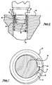
- Figure 2 is a partial sectional view of the extraction and adjustment tool of Figure 1;
- Figure 3 is a partial side view of a lead end of the extraction and adjustment tool of Figure 2;
- Figure 4 is an end view of the lead end of the extraction and adjustment tool of Figure 3;
- Figure 5 is a partial sectional view of the lead end of the extraction and adjustment tool as shown in Figures 3 and 4 removing a helically coiled wire insert in a bore of a parent material;
- Figure 6 is a partial sectional view of the lead end of the extraction and adjustment tool as shown in Figures 3 and 4 adjusting a helically coiled wire insert in a bore of a parent material;
- Figure 7 is a partially sectioned top view of the lead end of the extraction and adjustment tool as shown in Figures 5 and 6 engaging the inner diameter of the helically coiled wire insert;
- Figure 8 is a partially sectioned exploded view of the extraction and adjustment tool for tangless inserts with a series of mandrels according to the invention;
- Figure 9 is a side view of a screw-lock type insert for use with the extraction and adjustment tool of Figure 1;
- Figure 10 is a sectional view of the screw-lock type insert of Figure 9; and
- Figure 11 is a partial sectional view of the lead end of the extraction and adjustment tool as shown in Figures 3 and 4 adjusting a screw-lock type insert in a bore of a parent material.
-
- With reference to the drawings, and to Figures 1 and 2 in particular, a
tool 10 for use in adjusting and extracting helically coiled tangless wire inserts is shown. Tangless inserts are used, for example, where a steel fastener having conventional threads is desired to be fastened into a material of relatively softer alloy, such as aluminum.Tool 10 of the present invention includes abody 20 having ahandle 22 at one end and acoupler 24 at an opposite end.Coupler 24 selectively receives amandrel 30 and supportsmandrel 30 in removing or adjusting a tangless insert 14 in tappedhole 16 of aparent material 18, as illustrated in Figures 5, 6, and 11. - As shown in Figure 2, the
mandrel 30 includes anend 32 for insertion intocoupler 24 which selectively compresses abushing 28 onend 32.Coupler 24 includes anut portion 50 having an internal screw thread for tightening on an external screw thread cut inend portion 26 ofhandle 22. When fully tightened onend portion 26,nut portion 50 ofcoupler 24 compresses bushing 28 againstend 32 ofmandrel 30, thereby securingmandrel 30 tobody 20 oftool 10. Preferably, the diameter ofmandrel 30 pilots on the inner diameter of the tappedhole 16. - At an end
opposite end 32, themandrel 30 includes alead portion 34, which has alarger diameter portion 38 approximating an inner diameter of tangless insert 14 wheninsert 14 is installed in tappedhole 16 and expanded againstparent material 18. More specifically, thelarger diameter portion 38 oflead portion 34 is slightly smaller than the inner diameter ofinsert 14 in its installed state, thereby facilitating axial insertion into an installedinsert 14. Further, with reference to Figure 3,cylindrical lead portion 34 includes a smallerdiameter leading end 36 adjacent the larger diameterinner portion 38. Smallerdiameter leading end 36 is adapted to pilot on mid-grip flats of screw-lock type tangless inserts 14', as shown in Figure 11, and described further below. A ramped leadingedge 40 of thelead portion 34 facilitates insertion ofmandrel 30 into tangless insert 14. - As shown in Figures 5-7, tangless insert 14, such as that described in U.S. Patent No. 4,645,398, includes a
recess 12 on atrailing end 13. As shown best in Figure 7,recess 12 includes alead wall portion 54 generally raked between 5° to 15°. Also,recess 12 includes acamming surface 52 for locating the tooth or pawl of an extraction tool againstlead wall portion 54.Tool 10 uses thissame recess 12 for adjusting or removingtangless insert 14. - A left-hand driving
tooth 42 on thelarger diameter portion 38 is adapted to engage therecess 12 of trailingend 13 oftangless insert 14, as illustrated in Figure 5. As shown in Figure 4,tooth 42 includes a ramp 44 for camming onsurface 52 ofrecess 12 to facilitate removal oftooth 42 from therecess 12 of theinsert 14 and ashoulder 45 for hookinglead wall 54 ofrecess 12 to facilitate removal and adjustment ofinsert 14. Upon location oftooth 42 inrecess 12, left-hand rotation ofmandrel 30 causestooth 42 to hook inrecess 12, whereby insert 14 contracts aboutlead portion 34 ofmandrel 30. More specifically,shoulder 45strikes lead wall 54, forcinginsert 14 to tighten aboutlead portion 34, wherebyinsert 14 is no longer expanded againstparent material 18. Once contracted, continued left-hand driving force ofmandrel 30, against tangless insert 14 permits adjustment or removal. Upon proper adjustment, even slight right-hand rotation (approximately ¼ turn) ofmandrel 30 will disengagetooth 42 fromrecess 12 andreturn insert 14 to an expanded state againstparent material 18. - With reference to Figures 9-11, a screw-lock type insert 14' is illustrated. The insert 14' includes a reduced
coil 15, preferably disposed intermediately among the series of coils of insert 14'. As shown best in Figure 10, the reducedcoil 15 has a generally hexagonal inner diameter including mid-grip flats 17. The smallerdiameter leading end 36 of thelead portion 34 is adapted to pilot on the mid-grip flats 17 of the screw-lock type insert 14', as best shown in Figure 11. The engagement of thesmaller diameter portion 36 on the mid-grip flats 17 of the reducedcoil 15 facilitates removal and adjustment of the screw-lock type insert 14'. - To use
tool 10, the user simply insertslead portion 34 ofmandrel 30 into aninsert 14, 14' installed in tappedhole 16 ofparent material 18 untiltooth 42 isproximate recess 12 on thetrailing end 13 of theinsert 14, 14'. Left-hand rotation oftool 10 allows the user to locatetooth 42 inrecess 12. Once located,tooth 42 is positioned to adjust or removeinsert 14, 14' through left-hand rotation oftooth 42. For removal, continued left-hand rotation oftooth 42 removesinsert 14, 14' from tappedhole 16, whereupon right-hand rotation ofmandrel 30 relative toinsert 14, 14' will disengagetooth 42 fromrecess 12. For adjustment, selective left-hand rotation oftool 10 allows a user to properly locateinsert 14, 14' in tappedhole 16. Of course, a conventional installation tool (not shown) can be used withtool 10 to properly locateinsert 14, 14' through right-hand rotation ofinsert 14, 14'. This is significant because prior removal tools tended to damageinsert 14 if adjustment was attempted. In the case of an insert 14', the smallerdiameter leading end 36 of thelead portion 34 pilots on the mid-grip flats 17 of the screw-lock type insert 14' to further facilitate adjustment and/or removal of the insert 14'. - The
tool 10 allows adjustment or removal of a tanglesshelical coil insert 14, 14' after it has been installed in tappedhole 16 ofparent material 18.Tool 10 provides removal or adjustment of theinsert 14, 14' without causing damage to theinsert 14, 14' orparent material 18. Accordingly,tool 10 provides a relatively simple and inexpensive way to remove or adjust an incorrectly installed or damagedinsert 14, 14'. - While the
aforementioned tool 10 has been described as including asingle mandrel 30, it is preferred to provide a series ofmandrels 30 of different sizes corresponding to different-sizedtangless inserts 14, 14', as shown in Figure 8. Thus, an extraction andadjustment tool set 10 includes asingle tool body 20 for adjusting or removing different-sizedtangless inserts 14, 14' by simply selecting amandrel 30, 30', 30'', or 30''' corresponding in size to the tangless insert 14, 14' to be adjusted or removed.Coupler 24 provides simple connection of a selectedmandrel 30 to handle 22. Further,mandrel 30 includesend 32, which is sized for use with various commercial types of handles or other types of mechanical holders. As shown, mandrel body is generally circular in cross-section, but can be made any shape, such as square or hexagonal, for example. Accordingly,mandrel 30 according to the invention can be used independently ofbody 20 oftool 10. - Those skilled in the art can now appreciate from the foregoing description that the broad teachings of the present invention can be implemented in a variety of forms. Therefore, while this invention has been described in connection with particular examples thereof, the true scope of the invention should not be so limited since other modifications will become apparent to the skilled practitioner upon a study of the drawings, specification, and following claims.
Claims (19)
- An extraction and adjustment tool for tangless helically coiled wire inserts having a recess in a trailing end thereof, said tool comprising:a mandrel having a leading portion and an end opposite said leading portion, said leading portion including a tooth for reception of said recess of said insert for left-hand driving of said insert; anda body including a handle and connected to said end of said mandrel, whereby left-hand rotation of said handle contracts said insert about said leading portion of said mandrel to facilitate adjustment or removal of said insert.
- The extraction and adjustment tool according to claim 1, wherein said tooth includes a shoulder for hooking a lead wall of said recess upon left-hand rotation of said handle and a ramp for facilitating removal of said mandrel from said insert upon right-hand rotation of said handle.
- The extraction and adjustment tool according to claim 1, wherein said body includes a coupler for selectively securing said end of said mandrel to said handle.
- The extraction and adjustment tool according to claim 3, wherein said body includes a bushing for receiving said end of said mandrel and said coupler compresses said bushing about said end of said mandrel to selectively secure said mandrel to said handle.
- The removal and extraction tool according to claim 1, wherein said leading portion of said mandrel includes a smaller diameter leading end adjacent a larger diameter portion.
- The extraction and adjustment tool according to claim 5, wherein said smaller diameter leading portion includes a ramped leading edge.
- The extraction and adjustment tool according to claim 5 wherein said smaller diameter portion is adapted to pilot on mid-grip flats of said tangless helically coiled insert.
- A mandrel for use with a tool for adjusting or removing tangless helically coiled wire inserts having a recess and a trailing end thereof, said mandrel comprising:a body having a leading portion and an end opposite said leading portion, said leading portion including a tooth for reception in said recess of said insert for left-hand driving said insert, said end adapted to selectively secure said mandrel to said extraction and adjustment tool.
- The mandrel according to claim 8, wherein said tooth includes a shoulder for hooking a lead wall of said recess upon left-hand rotation of said mandrel and a ramp for facilitating removal of said mandrel from said insert upon right-hand rotation of said mandrel.
- The mandrel according to claim 8, wherein said leading portion of said mandrel includes a smaller diameter leading end adjacent a larger diameter portion.
- The mandrel according to claim 10, wherein said smaller diameter leading end includes a ramped leading edge.
- The mandrel according to claim 10 wherein said smaller diameter portion is adapted to pilot on mid-grip flats of said tangless helically coiled insert.
- An extraction and adjustment tool set for tangless helically coiled wire inserts having a recess and a trailing end thereof, said tool set comprising:multiple mandrels, each mandrel of said multiple mandrels having a leading portion and an end opposite said leading portion, each of said leading portions differing in diameter and including a tooth for reception in said recess of said insert for left-hand driving said insert; anda body including a handle and a bushing, said bushing selectively receiving said end of one of said multiple mandrels, whereby left-hand rotation of said handle contracts said insert about said leading portion of said mandrel to facilitate adjustment or removal of said insert, whereby a mandrel complementing an inner diameter of said insert is selected from said multiple mandrels to facilitate adjustment or removal of said insert.
- The extraction and adjustment tool set according to claim 13, wherein said tooth includes a shoulder for hooking a lead wall of said recess upon left-hand rotation of said handle and a ramp for facilitating removal of said mandrel from said insert upon right-hand rotation of said handle.
- The extraction and adjustment tool set according to claim 13, wherein said body includes a coupler for selectively securing said end of one of said multiple mandrels to said handle.
- The extraction and adjustment tool set according to claim 15, wherein said body includes a bushing for receiving said end of one of said multiple mandrels and said coupler compresses said bushing about said end to selectively secure one of said multiple mandrels to said handle.
- The extraction and adjustment tool set according to claim 13, wherein each of said leading portions includes a smaller diameter leading end adjacent a larger diameter portion.
- The extraction and adjustment tool set according to claim 17, wherein said smaller diameter leading portion includes a ramped leading edge.
- The extraction and adjustment tool set according to claim 17, wherein said smaller diameter leading end includes a ramped leading edge.
Applications Claiming Priority (4)
| Application Number | Priority Date | Filing Date | Title |
|---|---|---|---|
| US15416499P | 1999-09-15 | 1999-09-15 | |
| US154164P | 1999-09-15 | ||
| US09/596,035 US6421899B1 (en) | 1999-09-15 | 2000-06-15 | Extraction and adjustment tool for tangless inserts |
| US596035 | 2000-06-15 |
Publications (3)
| Publication Number | Publication Date |
|---|---|
| EP1084799A2 true EP1084799A2 (en) | 2001-03-21 |
| EP1084799A3 EP1084799A3 (en) | 2001-09-26 |
| EP1084799B1 EP1084799B1 (en) | 2007-11-14 |
Family
ID=26851213
Family Applications (1)
| Application Number | Title | Priority Date | Filing Date |
|---|---|---|---|
| EP00307714A Expired - Lifetime EP1084799B1 (en) | 1999-09-15 | 2000-09-06 | Extraction and adjustment tool for tangless inserts |
Country Status (4)
| Country | Link |
|---|---|
| US (1) | US6421899B1 (en) |
| EP (1) | EP1084799B1 (en) |
| JP (1) | JP2001150363A (en) |
| DE (1) | DE60037082T2 (en) |
Cited By (4)
| Publication number | Priority date | Publication date | Assignee | Title |
|---|---|---|---|---|
| WO2003024669A1 (en) * | 2001-09-17 | 2003-03-27 | Newfrey, Llc | Extraction tool for tanged helically coiled inserts |
| DE10305467A1 (en) * | 2003-02-13 | 2004-08-26 | Alstom Technology Ltd | Removal tool for extracting spiral thread inserts and use of the removal tool |
| GB2469548A (en) * | 2009-02-27 | 2010-10-20 | Bofag Fastener Ag | Extraction tool and method for extracting a wire thread insert |
| CN113909876A (en) * | 2021-11-18 | 2022-01-11 | 内蒙古第一机械集团股份有限公司 | Intelligent press-fitting and tightening mechanism for steel wire thread insert |
Families Citing this family (50)
| Publication number | Priority date | Publication date | Assignee | Title |
|---|---|---|---|---|
| US6461364B1 (en) | 2000-01-05 | 2002-10-08 | Integrated Vascular Systems, Inc. | Vascular sheath with bioabsorbable puncture site closure apparatus and methods of use |
| US9579091B2 (en) | 2000-01-05 | 2017-02-28 | Integrated Vascular Systems, Inc. | Closure system and methods of use |
| US8758400B2 (en) | 2000-01-05 | 2014-06-24 | Integrated Vascular Systems, Inc. | Closure system and methods of use |
| US6391048B1 (en) | 2000-01-05 | 2002-05-21 | Integrated Vascular Systems, Inc. | Integrated vascular device with puncture site closure component and sealant and methods of use |
| AU8800801A (en) | 2000-09-08 | 2002-03-22 | James E Coleman | Surgical staple |
| US6626918B1 (en) | 2000-10-06 | 2003-09-30 | Medical Technology Group | Apparatus and methods for positioning a vascular sheath |
| US8690910B2 (en) | 2000-12-07 | 2014-04-08 | Integrated Vascular Systems, Inc. | Closure device and methods for making and using them |
| US7211101B2 (en) | 2000-12-07 | 2007-05-01 | Abbott Vascular Devices | Methods for manufacturing a clip and clip |
| US6623510B2 (en) | 2000-12-07 | 2003-09-23 | Integrated Vascular Systems, Inc. | Closure device and methods for making and using them |
| US7905900B2 (en) | 2003-01-30 | 2011-03-15 | Integrated Vascular Systems, Inc. | Clip applier and methods of use |
| US6695867B2 (en) | 2002-02-21 | 2004-02-24 | Integrated Vascular Systems, Inc. | Plunger apparatus and methods for delivering a closure device |
| IES20010547A2 (en) | 2001-06-07 | 2002-12-11 | Christy Cummins | Surgical Staple |
| US7850709B2 (en) | 2002-06-04 | 2010-12-14 | Abbott Vascular Inc. | Blood vessel closure clip and delivery device |
| US7080432B2 (en) * | 2002-10-04 | 2006-07-25 | Clyde Jewel Norwood | Piston pin spiral or wire lock ring insertion tool |
| US8905937B2 (en) | 2009-02-26 | 2014-12-09 | Integrated Vascular Systems, Inc. | Methods and apparatus for locating a surface of a body lumen |
| US8398656B2 (en) | 2003-01-30 | 2013-03-19 | Integrated Vascular Systems, Inc. | Clip applier and methods of use |
| US8202293B2 (en) | 2003-01-30 | 2012-06-19 | Integrated Vascular Systems, Inc. | Clip applier and methods of use |
| US8758398B2 (en) | 2006-09-08 | 2014-06-24 | Integrated Vascular Systems, Inc. | Apparatus and method for delivering a closure element |
| US8821534B2 (en) | 2010-12-06 | 2014-09-02 | Integrated Vascular Systems, Inc. | Clip applier having improved hemostasis and methods of use |
| IES20040368A2 (en) | 2004-05-25 | 2005-11-30 | James E Coleman | Surgical stapler |
| US8926633B2 (en) | 2005-06-24 | 2015-01-06 | Abbott Laboratories | Apparatus and method for delivering a closure element |
| US8313497B2 (en) | 2005-07-01 | 2012-11-20 | Abbott Laboratories | Clip applier and methods of use |
| US8808310B2 (en) | 2006-04-20 | 2014-08-19 | Integrated Vascular Systems, Inc. | Resettable clip applier and reset tools |
| JP4563967B2 (en) * | 2006-06-06 | 2010-10-20 | 本田技研工業株式会社 | Helisert tool and Helisert correction tool |
| US8556930B2 (en) * | 2006-06-28 | 2013-10-15 | Abbott Laboratories | Vessel closure device |
| US20090157101A1 (en) | 2007-12-17 | 2009-06-18 | Abbott Laboratories | Tissue closure system and methods of use |
| US8893947B2 (en) | 2007-12-17 | 2014-11-25 | Abbott Laboratories | Clip applier and methods of use |
| US7841502B2 (en) | 2007-12-18 | 2010-11-30 | Abbott Laboratories | Modular clip applier |
| US7587799B2 (en) * | 2007-12-19 | 2009-09-15 | Yu Hsin Li | Installation tool for helical coil inserts |
| US9282965B2 (en) | 2008-05-16 | 2016-03-15 | Abbott Laboratories | Apparatus and methods for engaging tissue |
| US8398676B2 (en) | 2008-10-30 | 2013-03-19 | Abbott Vascular Inc. | Closure device |
| US8858594B2 (en) | 2008-12-22 | 2014-10-14 | Abbott Laboratories | Curved closure device |
| US20100179589A1 (en) | 2009-01-09 | 2010-07-15 | Abbott Vascular Inc. | Rapidly eroding anchor |
| US9173644B2 (en) | 2009-01-09 | 2015-11-03 | Abbott Vascular Inc. | Closure devices, systems, and methods |
| US9089311B2 (en) | 2009-01-09 | 2015-07-28 | Abbott Vascular Inc. | Vessel closure devices and methods |
| US9414820B2 (en) | 2009-01-09 | 2016-08-16 | Abbott Vascular Inc. | Closure devices, systems, and methods |
| US9486191B2 (en) | 2009-01-09 | 2016-11-08 | Abbott Vascular, Inc. | Closure devices |
| US20100185234A1 (en) | 2009-01-16 | 2010-07-22 | Abbott Vascular Inc. | Closure devices, systems, and methods |
| US20110054492A1 (en) | 2009-08-26 | 2011-03-03 | Abbott Laboratories | Medical device for repairing a fistula |
| DE102010017739B4 (en) | 2010-07-05 | 2023-03-30 | Böllhoff Verbindungstechnik GmbH | Threaded armoring element, screw with threaded armoring element, installation method thereof, component with threaded armoring element installed, winding spindle for manufacturing a threaded armoring element, and manufacturing method of a threaded armoring element |
| US8758399B2 (en) | 2010-08-02 | 2014-06-24 | Abbott Cardiovascular Systems, Inc. | Expandable bioabsorbable plug apparatus and method |
| US9149276B2 (en) | 2011-03-21 | 2015-10-06 | Abbott Cardiovascular Systems, Inc. | Clip and deployment apparatus for tissue closure |
| US9332976B2 (en) | 2011-11-30 | 2016-05-10 | Abbott Cardiovascular Systems, Inc. | Tissue closure device |
| JP5815471B2 (en) * | 2012-05-29 | 2015-11-17 | 日本スプリュー株式会社 | Tongue-free spiral coil insert extraction tool |
| US9364209B2 (en) | 2012-12-21 | 2016-06-14 | Abbott Cardiovascular Systems, Inc. | Articulating suturing device |
| US9897347B2 (en) * | 2013-03-15 | 2018-02-20 | Thomas Scott Breidenbach | Screw-in geothermal heat exchanger systems and methods |
| US9597787B2 (en) | 2014-04-07 | 2017-03-21 | Newfrey Llc | Iinsertion tool |
| CN104369146A (en) * | 2014-11-05 | 2015-02-25 | 南岳电控(衡阳)工业技术有限公司 | Assembling assembly and method for fast installing steel wire swivel nut |
| JP6879581B2 (en) | 2019-06-04 | 2021-06-02 | 株式会社三友精機 | Tongue cutting tool and tongue breaking method |
| EP3915763B1 (en) | 2020-05-25 | 2024-04-17 | Böllhoff Verbindungstechnik GmbH | 3d print component and manufacturing method for same |
Citations (6)
| Publication number | Priority date | Publication date | Assignee | Title |
|---|---|---|---|---|
| GB215530A (en) * | 1923-04-03 | 1924-05-15 | Henry Butters Mackay Mcfarlane | Condenser ferrule extractor |
| GB224665A (en) * | 1923-10-01 | 1924-11-20 | John Hamilton | Ferrule extractor |
| US2244824A (en) * | 1939-01-24 | 1941-06-10 | Aireraft Screw Products Compan | Extracting tool |
| US2755699A (en) * | 1953-07-16 | 1956-07-24 | Heli Coil Corp | Wire coil screw thread insert with grip end having an angular configuration |
| US4553303A (en) * | 1984-02-21 | 1985-11-19 | Rexnord Inc. | Removal tool for tangless, helically coiled insert |
| US5309617A (en) * | 1993-06-07 | 1994-05-10 | Thiokol Corporation | Threaded insert removal tool |
-
2000
- 2000-06-15 US US09/596,035 patent/US6421899B1/en not_active Expired - Fee Related
- 2000-09-06 DE DE60037082T patent/DE60037082T2/en not_active Expired - Lifetime
- 2000-09-06 EP EP00307714A patent/EP1084799B1/en not_active Expired - Lifetime
- 2000-09-08 JP JP2000272972A patent/JP2001150363A/en active Pending
Patent Citations (6)
| Publication number | Priority date | Publication date | Assignee | Title |
|---|---|---|---|---|
| GB215530A (en) * | 1923-04-03 | 1924-05-15 | Henry Butters Mackay Mcfarlane | Condenser ferrule extractor |
| GB224665A (en) * | 1923-10-01 | 1924-11-20 | John Hamilton | Ferrule extractor |
| US2244824A (en) * | 1939-01-24 | 1941-06-10 | Aireraft Screw Products Compan | Extracting tool |
| US2755699A (en) * | 1953-07-16 | 1956-07-24 | Heli Coil Corp | Wire coil screw thread insert with grip end having an angular configuration |
| US4553303A (en) * | 1984-02-21 | 1985-11-19 | Rexnord Inc. | Removal tool for tangless, helically coiled insert |
| US5309617A (en) * | 1993-06-07 | 1994-05-10 | Thiokol Corporation | Threaded insert removal tool |
Cited By (8)
| Publication number | Priority date | Publication date | Assignee | Title |
|---|---|---|---|---|
| WO2003024669A1 (en) * | 2001-09-17 | 2003-03-27 | Newfrey, Llc | Extraction tool for tanged helically coiled inserts |
| DE10305467A1 (en) * | 2003-02-13 | 2004-08-26 | Alstom Technology Ltd | Removal tool for extracting spiral thread inserts and use of the removal tool |
| US7131175B2 (en) | 2003-02-13 | 2006-11-07 | Alstom Technology Ltd. | Extraction tool for extracting spiral threaded inserts and use of the extraction tool |
| DE10305467B4 (en) * | 2003-02-13 | 2012-10-31 | Alstom Technology Ltd. | Removal tool for extracting spiral thread inserts and application of the removal tool |
| GB2469548A (en) * | 2009-02-27 | 2010-10-20 | Bofag Fastener Ag | Extraction tool and method for extracting a wire thread insert |
| GB2469548B (en) * | 2009-02-27 | 2013-05-15 | Bofag Fastener Ag | Extraction tool and method for extracting a wire thread insert |
| CN113909876A (en) * | 2021-11-18 | 2022-01-11 | 内蒙古第一机械集团股份有限公司 | Intelligent press-fitting and tightening mechanism for steel wire thread insert |
| CN113909876B (en) * | 2021-11-18 | 2023-11-17 | 内蒙古第一机械集团股份有限公司 | Intelligent press-fitting screwing mechanism for steel wire thread sleeve |
Also Published As
| Publication number | Publication date |
|---|---|
| EP1084799A3 (en) | 2001-09-26 |
| DE60037082T2 (en) | 2008-09-11 |
| DE60037082D1 (en) | 2007-12-27 |
| EP1084799B1 (en) | 2007-11-14 |
| JP2001150363A (en) | 2001-06-05 |
| US6421899B1 (en) | 2002-07-23 |
Similar Documents
| Publication | Publication Date | Title |
|---|---|---|
| US6421899B1 (en) | Extraction and adjustment tool for tangless inserts | |
| US6361258B1 (en) | Permanently placeable fasteners, inserter head for fastener placement and related methods | |
| EP0153267B1 (en) | Removal tool for tangless helically coiled insert | |
| EP0438965B1 (en) | Front end assembly installation tool for helical coil wire inserts | |
| EP3814060B1 (en) | Fastener extractor device | |
| EP0153266B1 (en) | Adapter for power tool installation of tangless helically coiled insert | |
| EP0580544A1 (en) | Tools for installation of both tanged and tangless wire inserts | |
| EP2845673B1 (en) | Arbor assembly and method of assembly | |
| EP2252421A1 (en) | Quick change arbor, hole cutter, and method | |
| AU2002241870A1 (en) | Self-tapping insert, insert assembly, and method for mounting the insert | |
| US7308746B2 (en) | Fastener removal apparatus and associated method | |
| AU2001266565A1 (en) | Thread replacement system and device | |
| US8087328B2 (en) | Adjustable one way screw remover | |
| US6588305B2 (en) | Notch-forming extraction tool for helical inserts | |
| EP0140812B1 (en) | Tangless helically coiled insert | |
| US20110197410A1 (en) | Frangible collar removal tool | |
| US10773365B2 (en) | Installation tool for a wire thread insert having an installation pin that can be bent back, and installation method | |
| US6726421B2 (en) | Tanged screw thread inserts with improved removability | |
| US20080104814A1 (en) | Semiautomatic installation tool | |
| JP2000084714A (en) | Disassembling tool for connecting member | |
| EP2230434A1 (en) | Bite type pipe connection structure, valve, bite type pipe joint, and freezing apparatus | |
| WO2020128881A1 (en) | Orthopaedic tool |
Legal Events
| Date | Code | Title | Description |
|---|---|---|---|
| PUAI | Public reference made under article 153(3) epc to a published international application that has entered the european phase |
Free format text: ORIGINAL CODE: 0009012 |
|
| 17P | Request for examination filed |
Effective date: 20000916 |
|
| AK | Designated contracting states |
Kind code of ref document: A2 Designated state(s): AT BE CH CY DE DK ES FI FR GB GR IE IT LI LU MC NL PT SE Kind code of ref document: A2 Designated state(s): DE FR GB |
|
| AX | Request for extension of the european patent |
Free format text: AL;LT;LV;MK;RO;SI |
|
| PUAL | Search report despatched |
Free format text: ORIGINAL CODE: 0009013 |
|
| AK | Designated contracting states |
Kind code of ref document: A3 Designated state(s): AT BE CH CY DE DK ES FI FR GB GR IE IT LI LU MC NL PT SE |
|
| AX | Request for extension of the european patent |
Free format text: AL;LT;LV;MK;RO;SI |
|
| AKX | Designation fees paid |
Free format text: DE FR GB |
|
| RAP1 | Party data changed (applicant data changed or rights of an application transferred) |
Owner name: EMHART LLC |
|
| RAP1 | Party data changed (applicant data changed or rights of an application transferred) |
Owner name: NEWFREY LLC |
|
| RAP1 | Party data changed (applicant data changed or rights of an application transferred) |
Owner name: NEWFREY LLC |
|
| GRAP | Despatch of communication of intention to grant a patent |
Free format text: ORIGINAL CODE: EPIDOSNIGR1 |
|
| GRAS | Grant fee paid |
Free format text: ORIGINAL CODE: EPIDOSNIGR3 |
|
| GRAA | (expected) grant |
Free format text: ORIGINAL CODE: 0009210 |
|
| AK | Designated contracting states |
Kind code of ref document: B1 Designated state(s): DE FR GB |
|
| REG | Reference to a national code |
Ref country code: GB Ref legal event code: FG4D |
|
| REF | Corresponds to: |
Ref document number: 60037082 Country of ref document: DE Date of ref document: 20071227 Kind code of ref document: P |
|
| ET | Fr: translation filed | ||
| PLBE | No opposition filed within time limit |
Free format text: ORIGINAL CODE: 0009261 |
|
| STAA | Information on the status of an ep patent application or granted ep patent |
Free format text: STATUS: NO OPPOSITION FILED WITHIN TIME LIMIT |
|
| 26N | No opposition filed |
Effective date: 20080815 |
|
| PGFP | Annual fee paid to national office [announced via postgrant information from national office to epo] |
Ref country code: GB Payment date: 20090929 Year of fee payment: 10 |
|
| PGFP | Annual fee paid to national office [announced via postgrant information from national office to epo] |
Ref country code: DE Payment date: 20090929 Year of fee payment: 10 |
|
| GBPC | Gb: european patent ceased through non-payment of renewal fee |
Effective date: 20100906 |
|
| REG | Reference to a national code |
Ref country code: FR Ref legal event code: ST Effective date: 20110531 |
|
| REG | Reference to a national code |
Ref country code: DE Ref legal event code: R119 Ref document number: 60037082 Country of ref document: DE Effective date: 20110401 |
|
| PG25 | Lapsed in a contracting state [announced via postgrant information from national office to epo] |
Ref country code: FR Free format text: LAPSE BECAUSE OF NON-PAYMENT OF DUE FEES Effective date: 20100930 Ref country code: DE Free format text: LAPSE BECAUSE OF NON-PAYMENT OF DUE FEES Effective date: 20110401 |
|
| PG25 | Lapsed in a contracting state [announced via postgrant information from national office to epo] |
Ref country code: GB Free format text: LAPSE BECAUSE OF NON-PAYMENT OF DUE FEES Effective date: 20100906 |
|
| PGFP | Annual fee paid to national office [announced via postgrant information from national office to epo] |
Ref country code: FR Payment date: 20091006 Year of fee payment: 10 |