EP1085705A2 - Network with several nodes and at least one network hub - Google Patents
Network with several nodes and at least one network hub Download PDFInfo
- Publication number
- EP1085705A2 EP1085705A2 EP00203163A EP00203163A EP1085705A2 EP 1085705 A2 EP1085705 A2 EP 1085705A2 EP 00203163 A EP00203163 A EP 00203163A EP 00203163 A EP00203163 A EP 00203163A EP 1085705 A2 EP1085705 A2 EP 1085705A2
- Authority
- EP
- European Patent Office
- Prior art keywords
- star
- network
- pilot signal
- node
- assigned
- Prior art date
- Legal status (The legal status is an assumption and is not a legal conclusion. Google has not performed a legal analysis and makes no representation as to the accuracy of the status listed.)
- Granted
Links
Images


Classifications
-
- H—ELECTRICITY
- H04—ELECTRIC COMMUNICATION TECHNIQUE
- H04L—TRANSMISSION OF DIGITAL INFORMATION, e.g. TELEGRAPHIC COMMUNICATION
- H04L12/00—Data switching networks
- H04L12/28—Data switching networks characterised by path configuration, e.g. LAN [Local Area Networks] or WAN [Wide Area Networks]
- H04L12/44—Star or tree networks
Definitions
- the invention relates to a network with several network nodes.
- Such networks can, for example, in motor vehicles, in industrial automation (e.g. sensor systems) and home automation (e.g. lighting technology, alarm systems, heating system, Air conditioning technology etc.).
- industrial automation e.g. sensor systems
- home automation e.g. lighting technology, alarm systems, heating system, Air conditioning technology etc.
- TTP Time-Triggered Protocol
- This protocol enables secure data transmission and can therefore also be used in networks for safety-relevant devices (eg brakes).
- a bus system is mentioned as the network structure.
- the invention is based, another network with several mink nodes the task to accomplish.
- the idea on which this invention is based is the control of a star node by means of a pilot signal that is generated by the network nodes.
- the pilot signal will be before and after changed a message transmission so that one contained in the star node and one Star interface assigned to network nodes detects when the assigned network node does this Pilot signal changed.
- the other star interfaces then become like this in the star node switched that they only receive a message from the star interface that a message received from the assigned network node.
- the star interfaces ensure correct line termination at the input of a Star interface reached and by means of the pilot signal a clear control of the Enables traffic.
- each network node in the network is a specific, periodic repeating period of time assigned to send his messages.
- the Pilot signal generator in a network node signals when a pilot signal is sent this period.
- the pilot signal can be different from the actual one Message can be distinguished. For example, the pilot signal uses a different one Frequency range as the signal with the message to be transmitted.
- Claim 3 indicates that each star interface has a first and second switching element and contains a pilot signal detector.
- the switching elements can be a switchable amplifier, control depending on the pilot signal the flow of messages in a star interface.
- a star interface is generated during the transmission of messages by the pilot signal is displayed, an enable signal that via an OR link to the other star interfaces is supplied as described in claim 5.
- Claim 6 indicates that the OR link can be designed as an OR gate or as a wired-OR link can.
- pilot signal to control the message traffic enables this optionally adding redundant line connections such that for each additional Another star interface is added to the line connection. Beyond that the network node for each additional line connection by one circuit component for sending a message combined with a pilot signal and for Received such a message expanded. For fault finding and for selecting one A control unit is still required for the line connection.
- a line connection can be used, for example, for symmetrical signal transmission Line pair.
- the invention further relates to a star node in a network for coupling of multiple network nodes with multiple star interfaces that have at least one network node are assigned, and each in dependence on a pilot signal for forwarding a message from the assigned network node to the other star interfaces or from another star interface to at least one of the assigned Network nodes are provided.
- FIG. 1 An embodiment of the network according to the invention is shown in FIG. 1.
- This network contains, for example, four network nodes 1 to 4, each of which is coupled to one another via an active star node 9 via twisted line pairs 5 to 8 (twisted pair) provided for symmetrical signal transmission.
- the active star node 9 carries out a line adaptation, so that the line pairs 5 to 8 in the active star node 9 are terminated with the characteristic impedance, and detects a pilot signal transmitted by a network node 1 to 4. If the line pairs 5 to 8 were connected to each other without an active star node 9, a mismatch would result for each line pair in the star point due to the impedance jump from Z 0 to 1/3 Z 0 , which is caused by the parallel connection of the other line pairs.
- each network node 1 to 4 also contains a pilot signal generator.
- the active star node 9 contains a star interface for each line pair 5 to 8 forwarding the messages of a sending network node to all others on active star connected network node.
- An embodiment of a such a star interface is shown in FIG. 2.
- a pair of lines 5 to 8 is with the inputs of a switchable amplifier 10, with the outputs of another switchable Amplifier 11, with a pilot signal detector 12 and with a terminating resistor 13 connected.
- the value of the terminating resistor 13 corresponds to the characteristic impedance and is used for correct line termination.
- pilot signal detector 12 If the pilot signal detector 12 is a pilot signal detected, this generates an enable signal, which to a switching input 14 of the switchable amplifier 10, to an inverting input of an AND gate 15 and via an amplifier 17 and a line 18 to an OR gate 23 (FIG. 3) becomes. If the switchable amplifier 10 is released, this supplies data to one a data line 19 carrying a connection point. From this data line 19 data is also received from the other star interfaces and via the switchable Amplifier 11 passed to the associated line pair. Via a line 20 still the non-inverting input of the AND gate 15, an enable signal via the OR gate 23 (Fig. 3) supplied by another star interface. The non-inverting Output of the AND gate 15 is with a switching input 21 of the switchable Amplifier 11 and via an inverter 16 with an enable input 22 of the pilot signal detector connected.
- a switchable amplifier 10 or 11 can also be connected in series from the amplifier and Switch (switching element) are executed. When this switch is closed the output signal of the amplifier is passed on.
- the pilot signal detector checks whether the assigned network node by sending the Pilot signal shows that it is transmitting messages or data. If so, it will the amplifier 11 deactivated (in general it will already be in this state) and the amplifier 10 activated or released. That of the assigned line pair incoming message signal is routed to line 19 and thus to the others Star interfaces passed. In addition, the pilot signal detector 12 generated release signal to the other star interfaces signals that they in turn their Amplifier 11 should activate or release the messages to the respective forward assigned network nodes.
- the lines 18 of all star interfaces in the OR gate 23 linked. 3 shows four star interfaces 24 to 27, each with the line pairs 5 to 8 are coupled.
- the output of the OR gate 23 is with the Lines 20 (Fig. 2) each star interface 24 to 27 connected.
- the lines 19 (Fig. 2) each star interface 24 to 27 are connected to one another via a circuit node 28 connected.
- the enable signal transported via line 20 (FIG. 2) is activated via AND gates 15 and inverter 16 for suppressing the enable signal for the pilot signal detector 12 used.
- the amplifier 10 is thus also connected via its switching input 14 switched off or deactivated.
- the pilot signal detector 12, the pilot signal of which causes however, the assigned star interface receives or is to receive data still active in order to be able to recognize the end of the data transmission.
- the star node 9 In order for the active star node 9 to function properly, it is necessary that the network nodes 1 to 4 send their messages in a non-overlapping manner. Furthermore it must be ensured that there is no network node for the duration of a certain dead time is active or sends messages or data. In this state, the star node switched completely impermeable (i.e. all amplifiers 10 and 11 are deactivated). In this State, a star interface 24 to 27 in the star node 9 waits for a new pilot signal, with which a transmission request of messages is specified.
- the pilot signal is always before the start of the actual message transmission must be sent out. Only then is it ensured that the active Star node 9 is configured in time and also the start of the message all reached another network node.
- FIG. 4 shows the manner in which the pilot signal in a network node 1 to 4 generated and transmitted over a pair of lines 5 to 8.
- a network node is one
- a pilot signal generator receives a message or data to send to other network nodes 29 via a line 30, for example a start signal.
- the pilot signal generator 29 then supplies a pilot signal to a multiplexer 31, which is still supplied by a line 32 sending data are supplied.
- the signal output from the multiplexer 31 becomes given via an amplifier 33 to the assigned line pair.
- One from another Node-derived signal is transmitted from the line pair via an amplifier 34 led to a line 35 for further processing.
- the multiplexer shown in Fig. 4 can be used both as a time multiplexer (sending the Pilot signal as start and stop signal before and after the actual message) or be designed as a frequency multiplexer.
- the pilot signal is either as a continuous signal can accompany the entire message to be transmitted or that it is can be sent in the form of a start and stop signal.
- a start and stop signal e.g. by Different duration can be ensured that the start and stop signal are sufficient distinguish and the change between transmission period and transmission pause is not confused.
- the pilot signal can be generated in various ways.
- One possibility is that it can be a periodic signal whose frequency range lies outside the frequency range used for the transmission of the messages. This frequency range can be above or below the useful frequency band, but also with a corresponding specification of the useful band due to the narrow-band nature of the pilot signal in Gaps "of the useful frequency band.
- Another possibility is to transmit the actual message as a balanced push-pull signal and the pilot signal as a common-mode signal.
- the common-mode signal can be designed both in the form of a constant voltage and in the form of a periodic signal.
- a third possibility for the pilot signal is that this is realized in the form of message transmission of special symbols placed in front and behind.
- the proposed invention is particularly well suited for use in networks that work according to the TTP protocol for real-time communication, for example in a motor vehicle (cf. electronics booklet 14/1999: TTP: Drive by Wire "within reach", pages 36 to 43).
- TDMA Time Division Multiple Access
- a dead time interframe gap
- the TDMA method thus ensures that only one network node may ever send a message at a predetermined time and, for this purpose, activates or initiates the star interface assigned to it for forwarding messages by means of the pilot signal it sends out in the star node.
- bus guardian bus guardian
- This control signal can be used immediately
- Control of the pilot signal generator 29 can be used by this control signal the line 30 is supplied to the pilot signal generator 29.
- this control signal is identified by BG and the actual message by data.
- the control signal BG is, for example, during the transmission of a message in a low condition. During this low state of the control signal, the Message to be transmitted.
- a first time period T1 after a change in the control signal in the low state and a second period T2 before a change of Control signals in the high state must be selected so that the active Star node 9 is configured correctly and remains to transmit a message without errors to be able to. It remains to be mentioned that the TTP protocol is different (Constant) message delay times between different network nodes in the network supported. This violates that caused by the active star node 9 Delay time not against the TTP protocol.
- the network according to the invention enables the transmission of a pilot signal with everyone Type of signal transmission for the messages from a network node 1 to 4.
- a symmetrical push-pull transmission can be used for message transmission, Single wire transmission or carrier frequency modulated transmission can be selected.
- a supply voltage can be transmitted.
- FIG. 6 Another embodiment of a network is shown in FIG. 6.
- This network is with the network shown in Fig. 1 (mink nodes 1 to 4 and line pairs 5 to 8) almost identical except for four additional network nodes 36 to 39.
- the network node 36 is coupled directly to the active star node 9 via a further line pair 40.
- the network node 37 is connected to the line pair 5 via a line pair 41.
- the Network node 38 is via a line pair 42 with line pair 8 and the network node 39 connected to the line pair 42 via a line pair 43.
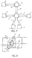
- FIG. 7 again shows the one known from FIG. 1 Topology of the network with nodes 1 to 4, line pairs 5 to 8 and the active star node 9.
- the active star node 9 is connected via a line pair 44 coupled to another active star node 45, to which in turn further network nodes can be connected.
- a network node 46 is shown here as an example.
- FIG. 8 shows a star interface suitable for the wired-OR connection.
- This star interface according to FIG. 8 is identical to the star interface of FIG. 2 except for the circuit-like connection of the output of the amplifier 17.
- the output of the amplifier 17 is thus connected to the inverting input of the AND gate 15.
- the amplifier 17 is shown in FIG Push-Pull "amplifier and in Fig. 8 as Open Collector "- or Open-drain "amplifier realized.
- the OR gate 23 is omitted in the active star node 9 and the result is a simple one Expandability of the network with further network nodes by eliminating the otherwise OR gate to be kept in different variants.
- the star interfaces 24 to 27 are connected to their respective lines 19 and 20 in this case, so that thereby forming two circuit nodes 47 and 48, as shown in FIG. 9.
- the resistor 49 the one with the circuit node 47 and the other is coupled to a supply voltage. This resistance forms together with the amplifiers 17 of each star interface, the wired OR link.
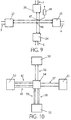
- the network of Fig. 10 contains four nodes 50 to 53 and a star node 54.
- the nodes 50 and 51 are via a pair of lines 56 and 57 and the nodes 52 and 53 via two each Line pairs 58 to 61 coupled to the star node 54. That means the network node 52 via the line pair 58 and 59 and the network node 53 via the line pair 60 and 61 is connected to the star node 54.
- FIG. 11 shows how a pilot signal is generated in a network node 52 and 53 and is sent over one of the line pairs 64 or 65.
- To generate a pilot signal serve the pilot signal generators 66 and 67.
- the lines 68 or 69 of a control unit 82 determine which pilot signal generator (66 or 67) generates a pilot signal.
- the pilot signal generator 66 or 67 delivers such a pilot signal to an associated multiplexer 70 or 71.
- the multiplexer 70 or 71 still receives a message or data via a line 72 or 73.
- the output signal of the multiplexer 70 or 71 is switched via a switchable amplifier 74 or 75 supplied to the respective line pair 64 or 65.
- Data originating from the star node 54 are transmitted via the line pair 64 or 65 fed to an amplifier 76 or 77.
- the amplifier 76 or 77 delivers the data a line 78 or 79 to further circuit components of the network node.
- a pilot signal detector 80 or 81 is connected to the output of each amplifier 76 or 77 connected.
- a control unit 82 state machine
- This control unit 82 controls the two switchable amplifiers 74 and 75.
- the control unit 82 controls the pilot signal generators 66 and 67 via lines 68 and 69.
- From the network node the start signal mentioned above is led on a line 83 to the control unit 82, which forms a control signal for the pilot signal generators 66 and 67.
- control unit 82 can report states to the network node, for example.
- circuit elements 66, 68, 70, 72, 74, 76, 78 and 80 form a first circuit component 85 and the circuit elements 67, 69, 71, 73, 75, 77, 79 and 81 a second Circuit component 86.
- Circuit components 85 and 86 are each identical built up.
- This control unit 82 manages the line pairs 64 and connected to the network node 65 so that the functionality of the line pairs 64 and 65 and the Circuit components 85 and 86 is checked.
- the control unit 82 checks whether the pilot signal actually arrives via both line pairs 64 and 65 - the arrival of one Pilot signal on one of the two redundant line pairs signals the start of one Receiving messages.
- the controller 82 checks during a particular one Time period whether after the arrival of the first pilot signal on one of the line pairs 64 or 65 the pilot signal has arrived on the other pair of lines. If not Case, it can be assumed that the other pair of lines is faulty.
- control unit 82 If there is no error and the control unit 82 has both line pairs 64 and 65 and has registered the two circuit components 85 and 86 as functional, for example, the circuit components 85 and 86 alternate with that send assigned star interface. In the event of an error, only the sends as error-free registered circuit component 85 or 86.
Abstract
Description
Die Erfindung bezieht sich auf ein Netzwerk mit mehreren Netzknoten. Solche Netzwerke können beispielsweise in Kraftfahrzeugen, in der Industrieautomatisierung (z.B. Sensorsysteme) und Hausautomatisierung (z.B. Lichttechnik, Alarmanlagen, Heizungsanlage, Klimatechnik etc.) eingesetzt werden.The invention relates to a network with several network nodes. Such networks can, for example, in motor vehicles, in industrial automation (e.g. sensor systems) and home automation (e.g. lighting technology, alarm systems, heating system, Air conditioning technology etc.).
In einem solchen Netzwerk für die Kraftfahrzeugtechnik kann z.B. das aus der Zeitschrift
![]()
![]()
Der Erfindung liegt die Aufgabe zugrunde, ein anderes Netzwerk mit mehreren Nerzknoten zu schaffen.The invention is based, another network with several mink nodes the task to accomplish.
Die Aufgabe wird durch ein Netzwerk der eingangs genannten Art dadurch gelöst,
dass wenigstens ein Teil der Netzknoten über wenigstens einen Sternknoten direkt
miteinander gekoppelt sind,
Die dieser Erfindung zugrundeliegende Idee ist die Steuerung eines Sternknotens mittels eines Pilotsignals, das von den Netzknoten erzeugt wird. Das Pilotsignal wird vor und nach einer Nachrichtenübertragung so geändert, dass eine im Sternknoten enthaltene und einem Netzknoten zugeordnete Sternschnittstelle erkennt, wenn der zugeordnete Netzknoten das Pilotsignal verändert. Im Sternknoten werden dann die anderen Sternschnittstellen so geschaltet, dass sie nur eine Nachricht von der Sternschnittstelle erhalten, die eine Nachricht von dem zugeordneten Netzknoten empfängt.The idea on which this invention is based is the control of a star node by means of a pilot signal that is generated by the network nodes. The pilot signal will be before and after changed a message transmission so that one contained in the star node and one Star interface assigned to network nodes detects when the assigned network node does this Pilot signal changed. The other star interfaces then become like this in the star node switched that they only receive a message from the star interface that a message received from the assigned network node.
Durch die Sternschnittstellen wird ein korrekter Leitungsabschluss am Eingang einer Sternschnittstelle erreicht und mittels des Pilotsignals eine eindeutige Steuerung des Nachrichtenverkehrs ermöglicht.The star interfaces ensure correct line termination at the input of a Star interface reached and by means of the pilot signal a clear control of the Enables traffic.
Wie Patentanspruch 2 zeigt, ist jedem Netzknoten im Netzwerk eine bestimmter, periodisch
sich wiederholender Zeitabschnitt zur Sendung seiner Nachrichten zugeordnet. Der
Pilotsignalgenerator in einem Netzknoten signalisiert bei Aussendung eines Pilotsignals
diesen Zeitabschnitt. Das Pilotsignal kann auf verschiedene Weise von der Eigentlichen
Nachricht unterschieden werden. Beispielsweise verwendet das Pilotsignal einen anderen
Frequenzbereich als das Signal mit der zu übertragenden Nachricht.As
Patentanspruch 3 gibt ein an, dass jede Sternschnittstelle ein erstes und zweites Schaltelement
und einen Pilotsignaldetektor enthält. Die Schaltelemente, die, wie Anspruch 3
beschreibt, ein schaltbarer Verstärker sein können, steuern in Abhängigkeit vom Pilotsignal
den Nachrichtenfluss in einer Sternschnittstelle.
Eine Sternschnittstelle erzeugt während der Nachrichtenübertragung, die vom Pilotsignal
angezeigt wird, ein Freigabesignal, dass über eine ODER-Verknüpfung den anderen Sternschnittstellen
zugeführt wird, wie Anspruch 5 beschreibt. Anspruch 6 gibt an, dass die
ODER-Verknüpfung als ODER-Gatter oder als Wired-OR-Verknüpfung ausgebildet sein
kann.A star interface is generated during the transmission of messages by the pilot signal
is displayed, an enable signal that via an OR link to the other star interfaces
is supplied as described in
Die Verwendung eines Pilotsignals zur Steuerung des Nachrichtenverkehrs ermöglicht das wahlweise Hinzufügen redundanter Leitungsverbindungen derart, dass für jede zusätzliche Leitungsverbindung eine weitere Sternschnittstelle hinzugefügt wird. Darüber hinaus wird der Netzknoten für jede zusätzliche Leitungsverbindung um jeweils eine Schaltungskomponente zur Sendung einer mit einem Pilotsignal kombinierten Nachricht und zum Empfang einer solchen Nachricht erweitert. Zur Fehlerfindung und zur Auswahl einer Leitungsverbindung wird noch ein Steuerwerk benötigt.The use of a pilot signal to control the message traffic enables this optionally adding redundant line connections such that for each additional Another star interface is added to the line connection. Beyond that the network node for each additional line connection by one circuit component for sending a message combined with a pilot signal and for Received such a message expanded. For fault finding and for selecting one A control unit is still required for the line connection.
Eine Leitungsverbindung kann beispielsweise bei symmetrischer Signalübertragung ein Leitungspaar sein.A line connection can be used, for example, for symmetrical signal transmission Line pair.
Die Erfindung bezieht sich auch auf einen Netzknoten, der dadurch gekennzeichnet ist,
Ferner bezieht sich die Erfindung auf einen Sternknoten in einem Netzwerk zur Kopplung von mehreren Netzknoten mit mehreren Sternschnittstellen, die wenigstens einem Netzknoten zugeordnet sind, und die jeweils in Abhängigkeit von einem Pilotsignal zur Weiterleitung einer Nachricht von dem zugeordneten Netzknoten zu den anderen Sternschnittstellen oder von einer anderen Sternschnittstelle zu wenigstens einem der zugeordneten Netzknoten vorgesehen sind.The invention further relates to a star node in a network for coupling of multiple network nodes with multiple star interfaces that have at least one network node are assigned, and each in dependence on a pilot signal for forwarding a message from the assigned network node to the other star interfaces or from another star interface to at least one of the assigned Network nodes are provided.
Ausführungsbeispiele der Erfindung werden nachstehend anhand der Fig. näher erläutert. Es zeigen:
- Fig. 1
- ein Netzwerk in Sternstruktur mit mehreren Netzknoten, die über einen aktiven Sternknoten gekoppelt sind,
- Fig. 2
- eine erste Ausführungsform einer Sternschnittstelle in einem Sternknoten,
- Fig. 3
- eine erste Ausführungsform eines ersten Sternknotens,
- Fig. 4
- einen Teil eines Netzknotens mit einem Pilotsignalgenerator,
- Fig. 5
- ein Teil eines Zeitverlaufs zweier Signale im Netzwerk,
- Fig. 6 und 7
- zwei weitere Ausführungsformen des Netzwerkes,
- Fig. 8
- eine zweite Ausführungsform einer Sternschnittstelle in einem Sternknoten,
- Fig. 9
- eine zweite Ausführungsform eines ersten Sternknotens,
- Fig. 10
- eine Ausführungsform des Netzwerks mit zusätzlichen redundanten Komponenten und
- Fig. 11
- eine weitere Ausführungsform eines Teil eines Netzknotens mit zwei Pilotsignalgeneratoren, -detektoren und einem Steuerwerk.
- Fig. 1
- a network in a star structure with several network nodes that are coupled via an active star node,
- Fig. 2
- a first embodiment of a star interface in a star node,
- Fig. 3
- a first embodiment of a first star node,
- Fig. 4
- part of a network node with a pilot signal generator,
- Fig. 5
- part of a time course of two signals in the network,
- 6 and 7
- two further embodiments of the network,
- Fig. 8
- a second embodiment of a star interface in a star node,
- Fig. 9
- a second embodiment of a first star node,
- Fig. 10
- an embodiment of the network with additional redundant components and
- Fig. 11
- a further embodiment of a part of a network node with two pilot signal generators, detectors and a control unit.
Ein Ausführungsbeispiel des erfindungsgemäßen Netzwerks ist in Fig. 1 dargestellt. Dieses
Netzwerk enthält beispielsweise vier Netzknoten 1 bis 4, die jeweils über verdrillte, für eine
symmetrische Signalübertragung vorgesehene Leitungspaare 5 bis 8 (twisted-pair) miteinander
über einen aktiven Sternknoten 9 gekoppelt sind. Der aktive Sternknoten 9 führt
eine Leitungsanpassung durch, so dass die Leitungspaare 5 bis 8 im aktiven Sternknoten 9
mit dem Wellenwiderstand abgeschlossen sind, und detektiert ein von einem Netzknoten 1
bis 4 ausgesendetes Pilotsignal. Wenn die Leitungspaare 5 bis 8 ohne aktiven Sternknoten
9 miteinander verbunden wären, entstände für jedes Leitungspaar im Sternpunkt eine
Fehlanpassung durch den Impedanzsprung von Z0 auf 1/3 Z0, die durch die Parallelschaltung
der jeweils anderen Leitungspaare verursacht wird. Zur Erzeugung eines Pilotsignals
enthält noch jeder Netzknoten 1 bis 4 einen Pilotsignalgenerator.An embodiment of the network according to the invention is shown in FIG. 1. This network contains, for example, four
Der aktive Sternknoten 9 enthält für jedes Leitungspaar 5 bis 8 eine Sternschnittstelle, die
eine Weiterleitung der Nachrichten eines sendenden Netzknotens zu allen anderen am
aktiven Stern angeschlossenen Netzknoten ermöglicht. Ein Ausführungsbeispiel einer
solchen Sternschnittstelle ist in Fig. 2 gezeigt. Ein Leitungspaar 5 bis 8 ist mit den Eingängen
eines schaltbaren Verstärkers 10, mit den Ausgängen eines weiteren schaltbaren
Verstärkers 11, mit einem Pilotsignaldetektor 12 und mit einem Abschlusswiderstand 13
verbunden. Der Wert des Abschlusswiderstandes 13 entspricht dem Wellenwiderstand und
dient damit zum korrekten Leitungsabschluss. Wenn der Pilotsignaldetektor 12 ein Pilotsignal
detektiert, erzeugt dieser ein Freigabesignal, welches zu einem Schalteingang 14 des
schaltbaren Verstärkers 10, zu einem invertierenden Eingang eines UND-Gatters 15 und
über einen Verstärker 17 und eine Leitung 18 zu einem ODER-Gatter 23 (Fig. 3) geführt
wird. Wenn der schaltbare Verstärker 10 freigegeben ist, liefert dieser Daten zu einer zu
einem Verknüpfungspunkt führenden Datenleitung 19. Von dieser Datenleitung 19
werden auch Daten von den anderen Sternschnittstellen empfangen und über den schaltbaren
Verstärker 11 zu dem zugeordneten Leitungspaar geleitet. Über eine Leitung 20 wird
noch dem nichtinvertierenden Eingang des UND-Gatters 15 ein Freigabesignal über das
ODER-Gatter 23 (Fig. 3) von einer anderen Sternschnittstelle geliefert. Der nichtinvertierende
Ausgang des UND-Gatters 15 ist mit einem Schalteingang 21 des schaltbaren
Verstärkers 11 sowie über einen Inverter 16 mit einem Freigabeeingang 22 des Pilotsignaldetektors
verbunden.The
Ein schaltbarer Verstärker 10 oder 11 kann auch als Reihenschaltung aus Verstärker und Schalter (Schaltelement) ausgeführt werden. Im geschlossenen Zustand dieses Schalters wird das Ausgangssignal des Verstärkers weitergeleitet.A switchable amplifier 10 or 11 can also be connected in series from the amplifier and Switch (switching element) are executed. When this switch is closed the output signal of the amplifier is passed on.
Der Pilotsignaldetektor überprüft, ob der zugeordnete Netzknoten durch Aussenden des
Pilotsignals zeigt, dass er Nachrichten bzw. Daten übertragen wird. Ist dies der Fall, wird
der Verstärker 11 deaktiviert (im allgemeinen wird er bereits in diesem Zustand sein) und
der Verstärker 10 aktiviert bzw. freigegeben. Das von dem zugeordneten Leitungspaar
kommende Nachrichtensignal wird zur Leitung 19 geführt und damit an die anderen
Sternschnittstellen weitergegeben. Zusätzlich wird durch das vom Pilotsignaldetektor 12
erzeugte Freigabesignal den anderen Sternschnittstellen signalisiert, dass sie ihrerseits ihren
Verstärker 11 aktivieren oder freigeben sollen, um die Nachrichten an die jeweiligen
zugeordneten Netzknoten weiterzuleiten.The pilot signal detector checks whether the assigned network node by sending the
Pilot signal shows that it is transmitting messages or data. If so, it will
the amplifier 11 deactivated (in general it will already be in this state) and
the amplifier 10 activated or released. That of the assigned line pair
incoming message signal is routed to
Wie in Fig. 3 dargestellt, werden die Leitungen 18 aller Sternschnittstellen in dem ODER-Gatter
23 verknüpft. Weiter zeigt Fig. 3 vier Sternschnittstellen 24 bis 27, die jeweils mit
den Leitungspaaren 5 bis 8 gekoppelt sind. Der Ausgang des ODER-Gatters 23 ist mit den
Leitungen 20 (Fig. 2) jeder Sternschnittstelle 24 bis 27 verbunden. Die Leitungen 19 (Fig.
2) jeder Sternschnittstelle 24 bis 27 sind miteinander über einen Schaltungsknoten 28
verknüpft.As shown in Fig. 3, the
Um zu verhindern, dass ein von einem Leitungspaar 5 bis 8 kommendes Signal in dasselbe
wieder zurückgespeist wird, wird über den invertierenden Eingang des UND-Gatters 15
der Verstärker 11 deaktiviert oder abgeschaltet. Um andererseits zu verhindern, dass der
einem anderen Netzknoten zugeordnete Pilotsignaldetektor seinerseits seinen Verstärker 10
aktiviert, wird das über die Leitung 20 (Fig. 2) transportierte Freigabesignal über UND-Gatter
15 und Inverter 16 zur Unterdrückung des Freigabesignals für den Pilotsignaldetektor
12 verwendet. Damit wird auch der Verstärker 10 über seinen Schalteingang 14
abgeschaltet oder deaktiviert. Der Pilotsignaldetektor 12, dessen Pilotsignal bewirkt, dass
die zugeordnete Sternschnittstelle Daten empfängt oder empfangen soll, bleibt allerdings
weiterhin aktiv, um das Ende der Datenübertragung erkennen zu können.To prevent a signal coming from a pair of
Zur einwandfreien Funktion des aktiven Sternknotens 9 ist es erforderlich, dass die Netzknoten
1 bis 4 ihre Nachrichten zeitlich nicht-überlappend versenden. Darüber hinaus
muss sichergestellt werden, dass für die Dauer einer gewissen Totzeit kein Netzknoten
aktiv ist oder Nachrichten bzw. Daten sendet. In diesem Zustand wird der Sternknoten
völlig undurchlässig geschaltet (d.h. alle Verstärker 10 und 11 sind deaktiviert). In diesem
Zustand wartet eine Sternschnittstelle 24 bis 27 in dem Sternknoten 9 auf ein neues Pilotsignal,
mit dem ein Übertragungswunsch von Nachrichten angegeben wird.In order for the
Grundsätzlich gilt, dass das Pilotsignal immer vor dem Beginn der tatsächlichen Nachrichtenübertragung
ausgesendet werden muss. Nur dann ist sichergestellt, dass der aktive
Sternknoten 9 rechtzeitig konfiguriert wird und auch der Beginn der Nachricht alle
anderen Netzwerkknoten erreicht.Basically, the pilot signal is always before the start of the actual message transmission
must be sent out. Only then is it ensured that the
In Fig. 4 ist dargestellt, auf welche Weise das Pilotsignal in einem Netzknoten 1 bis 4
erzeugt und über ein Leitungspaar 5 bis 8 übertragen wird. Wenn ein Netzknoten eine
Nachricht oder Daten zu anderen Netzknoten senden möchte, erhält ein Pilotsignalgenerator
29 über eine Leitung 30 beispielsweise ein Startsignal. Der Pilotsignalgenerator 29
liefert dann ein Pilotsignal zu einem Multiplexer 31, dem noch von einer Leitung 32 zu
sendende Daten zugeführt werden. Das von dem Multiplexer 31 abgegebene Signal wird
über einen Verstärker 33 auf das zugeordnete Leitungspaar gegeben. Ein von einem anderen
Netzknoten stammendes Signal wird von dem Leitungspaar über einen Verstärker 34
auf eine Leitung 35 zur weiteren Verarbeitung geführt.FIG. 4 shows the manner in which the pilot signal in a
Der in Fig. 4 gezeigte Multiplexer kann dabei sowohl als zeitlicher Multiplexer (Senden des Pilotsignals als Start- und Stopsignal jeweils vor und nach der eigentlichen Nachricht) oder als Frequenzmultiplexer ausgestaltet sein. Das bedeutet, dass das Pilotsignal entweder als ein andauerndes Signal die gesamte zu übertragene Nachricht begleiten kann oder dass es in Form eines Start- und Stopsignals ausgesendet werden kann. Dabei kann z.B. durch unterschiedliche Dauer sichergestellt werden, dass das Start- und Stopsignal sich hinreichend unterscheiden und der Wechsel zwischen Übertragungszeitraum und Übertragungspause nicht verwechselt wird.The multiplexer shown in Fig. 4 can be used both as a time multiplexer (sending the Pilot signal as start and stop signal before and after the actual message) or be designed as a frequency multiplexer. This means that the pilot signal is either as a continuous signal can accompany the entire message to be transmitted or that it is can be sent in the form of a start and stop signal. Here, e.g. by Different duration can be ensured that the start and stop signal are sufficient distinguish and the change between transmission period and transmission pause is not confused.
Das Pilotsignal kann auf verschiedene Weisen erzeugt werden. Eine Möglichkeit besteht
darin, dass es ein periodisches Signal sein kann, dessen Frequenzbereich außerhalb des für
die Übertragung der Nachrichten genutzten Frequenzbereiches liegt. Dieser Frequenzbereich
kann ober- oder unterhalb des Nutzfrequenzbandes liegen, aber auch bei
entsprechender Spezifikation des Nutzbandes aufgrund der schmalbandigen Natur des
Pilotsignals in
Die vorgeschlagene Erfindung eignet sich besonders gut für die Anwendung in Netzwerken,
die nach dem TTP-Protokoll für eine Echtzeit-Kommunikation beispielsweise im
Kraftfahrzeug arbeiten (vgl. Elektronik Heft 14/1999:
Ein zusätzlicher Vorteil besteht darin, dass zur Ansteuerung des sogenannten Bus-Wächters (bus guardian) ein Steuersignal im Nerzwerkknoten vorliegen muss, das zeitlich kurz vor dem Beginn der Nachrichtenübertragung liegt. Dieses Steuersignal kann unmittelbar zur Ansteuerung des Pilotsignalgenerators 29 verwendet werden, indem dieses Steuersignal auf der Leitung 30 dem Pilotsignalgenerator 29 zugeführt wird.An additional advantage is that to control the so-called bus guardian (bus guardian) there must be a control signal in the mink node that is shortly before the beginning of the message transmission. This control signal can be used immediately Control of the pilot signal generator 29 can be used by this control signal the line 30 is supplied to the pilot signal generator 29.
In Fig. 5 ist dieses Steuersignal mit BG und die eigentliche Nachricht mit data gekennzeichnet.
Das Steuersignal BG ist während der Aussendung einer Nachricht beispielsweise
in einem niedrigen Zustand. Während dieses niedrigen Zustandes des Steuersignals soll die
Nachricht übertragen werden. Ein erster Zeitraumes T1 nach einem Wechsel des Steuersignals
in den niedrigen Zustand und ein zweiter Zeitraum T2 vor einem Wechsel des
Steuersignals in den hohen Zustand müssen dabei so gewählt werden, dass der aktive
Sternknoten 9 korrekt konfiguriert ist und bleibt, um eine Nachricht fehlerlos übertragen
zu können. Es bleibt noch zu erwähnen, dass das TTP-Protokoll unterschiedliche
(konstante) Nachrichtenverzögerungszeiten zwischen verschiedenen Netzknoten im Netzwerk
unterstützt. Damit verstößt die durch den aktiven Sternknoten 9 hervorgerufene
Verzögerungszeit nicht gegen das TTP-Protokoll.5 this control signal is identified by BG and the actual message by data.
The control signal BG is, for example, during the transmission of a message
in a low condition. During this low state of the control signal, the
Message to be transmitted. A first time period T1 after a change in the control signal
in the low state and a second period T2 before a change of
Control signals in the high state must be selected so that the
Das erfindungsgemäße Netzwerk ermöglicht die Aussendung eines Pilotsignals mit jeder
Art von Signalübertragung für die Nachrichten von einem Netzknoten 1 bis 4. Beispielsweise
kann für die Nachrichtenübertragung eine symmetrische Gegentaktübertragung,
Einzelleiterübertragung oder trägerfrequenzmodulierte Übertragung gewählt werden. Bei
gleichtaktmäßiger Kopplung der Leitungspaare 5 bis 8 könnte ggf. auch mit der Nachrichtenübertragung
eine Versorgungsspannung übertragen werden.The network according to the invention enables the transmission of a pilot signal with everyone
Type of signal transmission for the messages from a
Ein weiteres Ausführungsbeispiel eines Netzwerkes ist in Fig. 6 dargestellt. Dieses Netzwerk
ist mit dem in der Fig. 1 dargestellten Netzwerk (Nerzknoten 1 bis 4 und Leitungspaare
5 bis 8) fast identisch bis auf vier zusätzliche Netzknoten 36 bis 39. Der Netzknoten
36 ist direkt über ein weiteres Leitungspaar 40 mit dem aktiven Sternknoten 9 gekoppelt.
Der Netzknoten 37 ist an das Leitungspaar 5 über ein Leitungspaar 41 angeschlossen. Der
Netzknoten 38 ist über ein Leitungspaar 42 mit dem Leitungspaar 8 und der Netzknoten
39 über ein Leitungspaar 43 mit dem Leitungspaar 42 verbunden.Another embodiment of a network is shown in FIG. 6. This network
is with the network shown in Fig. 1 (
Das in Fig. 7 gezeigte Ausführungsbeispiel zeigt wieder die aus der Fig. 1 bekannte
Topologie des Netzwerkes mit den Netzknoten 1 bis 4, den Leitungspaaren 5 bis 8 und
dem aktiven Sternknoten 9. Über ein Leitungspaar 44 ist der aktive Sternknoten 9 mit
einem weiteren aktiven Sternknoten 45 gekoppelt, an den wiederum weitere Netzknoten
angeschlossen sein können. Beispielhaft ist hier ein Netzknoten 46 eingezeichnet.The embodiment shown in FIG. 7 again shows the one known from FIG. 1
Topology of the network with
Anstelle des in der Fig. 3 benötigten ODER-Gatters 23 kann diese ODER-Verknüpfung
auch direkt durch eine Wired-OR-Verknüpfung realisiert werden. Eine für die Wired-OR-Verknüpfung
geeignete Sternschnittstelle zeigt Fig. 8. Diese Sternschnittstelle nach der Fig.
8 ist bis auf die schaltungsmäßige Verknüpfung des Ausgangs des Verstärkers 17 identisch
mit der Sternschnittstelle der Fig. 2. In der Fig. 8 führt der Ausgang des Verstärkers 17
nicht auf die Leitung 18, sondern auf die Leitung 20 (Wired-OR). Damit ist der Ausgang
des Verstärkers 17 mit dem invertierenden Eingang des UND-Gatters 15 verbunden. Der
Verstärker 17 ist in der Fig. 2 als
Durch diese Wired-OR-Verknüpfung verringert sich der Verdrahtungsaufwand und es
entfällt das ODER-Gatter 23 in dem aktiven Sternknoten 9 und es ergibt sich eine einfache
Erweiterbarkeit des Netzwerks mit weiteren Netzknoten durch Wegfall des ansonsten
in verschiedenen Varianten vorzuhaltenden ODER-Gatters. Die Sternschnittstellen 24 bis
27 sind in diesem Fall mit ihrem jeweiligen Leitungen 19 und 20 verbunden, so dass sich
dadurch, wie in Fig. 9 gezeigt, zwei Schaltungsknoten 47 und 48 bilden. Zusätzlich ist nur
ein Widerstand 49 vorzusehen, der einerseits mit dem Schaltungsknoten 47 und andererseits
mit einer Versorgungsspannung gekoppelt ist. Dieser Widerstand bildet zusammen
mit den Verstärkern 17 jeder Sternschnittstelle die Wired-OR-Verknüpfung.This wired-OR connection reduces the wiring effort and it
The
Um die Verfügbarkeit von Netzknoten in einem Netzwerk zu erhöhen, sind wie in Fig. 10
dargestellt, mehrere Leitungspaare und damit die zugeordnete Schaltungskomponente zur
Erzeugung eines Pilotsignals (vgl. Fig.4) verdoppelt. Das Netzwerk nach Fig. 10 enthält
vier Netzknoten 50 bis 53 und einen Sternknoten 54. Die Netzknoten 50 und 51 sind
über jeweils ein Leitungspaar 56 und 57 und die Netzknoten 52 und 53 über jeweils zwei
Leitungspaare 58 bis 61 mit dem Sternknoten 54 gekoppelt. Das bedeutet, dass der Netzknoten
52 über das Leitungspaar 58 und 59 und der Netzknoten 53 über das Leitungspaar
60 und 61 mit dem Sternknoten 54 verbunden ist.In order to increase the availability of network nodes in a network, as in FIG. 10
shown, several pairs of lines and thus the associated circuit component for
Generation of a pilot signal (see Fig. 4) doubled. The network of Fig. 10 contains
four
In Fig. 11 ist dargestellt, wie ein Pilotsignal in einem Netzknoten 52 und 53 erzeugt und
über eines der Leitungspaare 64 oder 65 gesendet wird. Zur Erzeugung eines Pilotsignals
dienen die Pilotsignalsgeneratoren 66 und 67. Durch Zuführung eines Steuersignals auf
den Leitungen 68 oder 69 von einem Steuerwerk 82 wird bestimmt, welcher Pilotsignalgenerator
(66 oder 67) ein Pilotsignal erzeugt. Der Pilotsignalgenerator 66 bzw. 67 liefert
ein solches Pilotsignal zu einem zugehörigen Multiplexer 70 bzw. 71. Der Multiplexer 70
bzw. 71 erhält noch eine Nachricht oder Daten über eine Leitung 72 bzw. 73. Das Ausgangssignal
des Multiplexers 70 bzw. 71 wird über einen schaltbaren Verstärker 74 bzw. 75
dem jeweiligen Leitungspaar 64 bzw. 65 zugeführt.FIG. 11 shows how a pilot signal is generated in a
Von dem Sternknoten 54 stammende Daten werden über das Leitungspaar 64 bzw. 65
einem Verstärker 76 bzw. 77 zugeleitet. Der Verstärker 76 bzw. 77 liefert die Daten über
eine Leitung 78 bzw. 79 zu weiteren Schaltungskomponenten des Netzknotens.Data originating from the
Mit dem Ausgang jedes Verstärkers 76 bzw. 77 ist ein Pilotsignaldetektor 80 bzw. 81
verbunden. Wenn von einen Pilotsignaldetektor 80 oder 81 ein Pilotsignal detektiert
worden ist, wird dies einem Steuerwerk 82 (state machine) mitgeteilt. Dieses Steuerwerk
82 steuert die beiden schaltbaren Verstärker 74 und 75. Ferner steuert das Steuerwerk 82
die Pilotsignalgeneratoren 66 und 67 über die Leitungen 68 und 69. Von dem Netzknoten
wird das schon oben erwähnte Startsignal auf einer Leitung 83 zum Steuerwerk 82 geführt,
welches daraus ein Steuersignal für die Pilotsignalgeneratoren 66 bzw. 67 bildet. Über eine
Leitung 84 kann das Steuerwerk 82 dem Netzknoten beispielsweise Zustände melden.A
Die Schaltungselemente 66, 68, 70, 72, 74, 76, 78 und 80 bilden eine erste Schaltungskomponente
85 und die Schaltungselemente 67, 69, 71, 73, 75, 77, 79 und 81 eine zweite
Schaltungskomponente 86. Die Schaltungskomponenten 85 und 86 sind jeweils identisch
aufgebaut. The
Dieses Steuerwerk 82 verwaltet die am Netzknoten angeschlossenen Leitungspaare 64 und
65 so, dass ständig die Funktionsfähigkeit der Leitungspaare 64 und 65 und der
Schaltungskomponente 85 und 86 überprüft wird.This
Während des Nachrichtenempfangs wird von dem Steuerwerk 82 geprüft, ob das Pilotsignal
tatsächlich über beide Leitungspaare 64 und 65 eintrifft- Das Eintreffen eines
Pilotsignals auf einem der beiden redundanten Leitungspaare signalisiert den Beginn eines
Nachrichtenempfangs. Das Steuerwerk 82 prüft während eines bestimmten
Zeitabschnittes, ob nach Eintreffen des ersten Pilotsignals auf einem der Leitungspaare 64
bzw. 65 das Pilotsignal auf dem anderen Leitungspaar eingetroffen ist. Ist dies nicht der
Fall, kann davon ausgegangen werden, dass das andere Leitungspaar fehlerhaft ist.During the message reception, the
Gesendet wird grundsätzlich nur auf einem der redundanten Leitungspaare. Um zu
erreichen, dass auch bei Ausfall einer Schaltungskomponente 85 bzw. 86 die
Kommunikation aufrechterhalten bleiben kann, wird bei jedem Sendevorgang geprüft, ob
tatsächlich das die Nachricht begleitende Pilotsignal ausgesendet wird. Der Aufbau des
Sternknotens stellt sicher, dass über das für das Aussenden einer Nachricht gerade nicht
verwendete Leitungspaar das Pilotsignal zum sendenden Netzknoten zurückgeführt wird.
Auch hierbei prüft das Steuerwerk 82, ob innerhalb eines anderen bestimmten Zeitabschnittes
nach Beginn der Aussendung der Nachricht das Pilotsignal auf dem anderen
Leitungspaar eintrifft.Basically, only one of the redundant line pairs is sent. In order to
achieve that even if a
Die Kombination dieser beiden Prüfungen erlaubt es, einen Defekt der zur Zeit für die
Aussendung von Nachrichten verwendete Schakungskomponente 85 bzw. 86 sowie der
Leitungspaare 64 bzw. 65 zu erkennen und die intakte Schaltungskomponente mit dem
zugeordneten intakten Leitungspaar von dem Steuerwerk 82 umzuschalten.The combination of these two tests allows a defect that is currently in use for the
Transmission of messages used
Wenn kein Fehler vorliegt und damit das Steuerwerk 82 beide Leitungspaare 64 und 65
und die beiden Schaltungskomponenten 85 und 86 als funktionsfähig registriert hat,
werden die Schaltungskomponenten 85 und 86 beispielsweise abwechselnd zu der
zugeordneten Sternschnittstelle senden. Im Fehlerfall sendet nur die als fehlerfrei
registrierte Schaltungskomponente 85 oder 86.If there is no error and the
Claims (11)
dadurch gekennzeichnet,
characterized by
dadurch gekennzeichnet,
characterized by
dadurch gekennzeichnet,
characterized by
dadurch gekennzeichnet,
characterized by
dadurch gekennzeichnet,
characterized by
dadurch gekennzeichnet,
characterized by
dadurch gekennzeichnet,
characterized by
dadurch gekennzeichnet,
characterized by
dadurch gekennzeichnet,
characterized by
Applications Claiming Priority (4)
| Application Number | Priority Date | Filing Date | Title |
|---|---|---|---|
| DE1999144597 DE19944597A1 (en) | 1999-09-16 | 1999-09-16 | Network with several network nodes and at least one star node, forwarding message from associated network node to other star interfaces in dependence on pilot signal |
| DE19944597 | 1999-09-16 | ||
| DE19944596 | 1999-09-16 | ||
| DE1999144596 DE19944596A1 (en) | 1999-09-16 | 1999-09-16 | Network with several network nodes and at least one star node, forwarding message from associated network node to other star interfaces in dependence on pilot signal |
Publications (3)
| Publication Number | Publication Date |
|---|---|
| EP1085705A2 true EP1085705A2 (en) | 2001-03-21 |
| EP1085705A3 EP1085705A3 (en) | 2003-10-22 |
| EP1085705B1 EP1085705B1 (en) | 2006-10-18 |
Family
ID=26054982
Family Applications (1)
| Application Number | Title | Priority Date | Filing Date |
|---|---|---|---|
| EP00203163A Expired - Lifetime EP1085705B1 (en) | 1999-09-16 | 2000-09-12 | Network with several nodes and at least one network hub |
Country Status (7)
| Country | Link |
|---|---|
| US (1) | US7099959B1 (en) |
| EP (1) | EP1085705B1 (en) |
| JP (1) | JP2001144792A (en) |
| KR (1) | KR100686397B1 (en) |
| CN (1) | CN1178433C (en) |
| DE (1) | DE50013628D1 (en) |
| ES (1) | ES2274763T3 (en) |
Cited By (5)
| Publication number | Priority date | Publication date | Assignee | Title |
|---|---|---|---|---|
| EP1179921A2 (en) * | 2000-08-10 | 2002-02-13 | Philips Corporate Intellectual Property GmbH | Activity detection in a hub coupled to a pluality of nodes |
| EP1213861A2 (en) * | 2000-12-07 | 2002-06-12 | Siemens Aktiengesellschaft | Node device for plural devices being connected by a serial data bus |
| WO2004100449A1 (en) * | 2003-05-08 | 2004-11-18 | Philips Intellectual Property & Standards Gmbh | Communication network and method of controlling the communication network |
| EP1801967A2 (en) * | 2005-12-22 | 2007-06-27 | Robert Bosch Gmbh | Active star point for use in a communications system with star topology |
| WO2008107217A1 (en) * | 2007-03-02 | 2008-09-12 | Robert Bosch Gmbh | Device for connecting an external device to a serial flexray data bus |
Families Citing this family (6)
| Publication number | Priority date | Publication date | Assignee | Title |
|---|---|---|---|---|
| WO2005053243A2 (en) * | 2003-11-19 | 2005-06-09 | Honeywell International Inc. | Priority based arbitration for tdma schedule enforcement in a multi-channel system in star configuration |
| US7366528B1 (en) * | 2004-01-13 | 2008-04-29 | At&T Mobility Ii Llc | Preventing wireless message delivery outside of specified times |
| EP2064841B1 (en) * | 2006-09-06 | 2017-08-02 | Nxp B.V. | Intelligent star coupler for time triggered communication protocol and method for communicating between nodes within a network using a time trigger protocol |
| DE102008014254B4 (en) * | 2008-03-13 | 2014-11-27 | Audi Ag | Star coupler for a bus system, bus system with such a star coupler and method for exchanging signals in a bus system |
| KR101536921B1 (en) * | 2009-01-07 | 2015-07-15 | 삼성전자주식회사 | Method and apparatus for synchronizing quiet period in cognitive radio system |
| DE102009026430A1 (en) * | 2009-05-25 | 2010-12-09 | Robert Bosch Gmbh | A vehicle sensor, system having a vehicle state determination control device and at least two vehicle sensors, and methods of operating a system including a vehicle state determination control device and at least two vehicle sensors |
Citations (3)
| Publication number | Priority date | Publication date | Assignee | Title |
|---|---|---|---|---|
| US4428046A (en) * | 1980-05-05 | 1984-01-24 | Ncr Corporation | Data processing system having a star coupler with contention circuitry |
| US5621895A (en) * | 1992-07-23 | 1997-04-15 | Alcatel Sel Aktiengesellschaft | Frame-structured bus system for transmitting both synchronous and asynchronous data over a star-coupled local operation network |
| US5784547A (en) * | 1995-03-16 | 1998-07-21 | Abb Patent Gmbh | Method for fault-tolerant communication under strictly real-time conditions |
Family Cites Families (18)
| Publication number | Priority date | Publication date | Assignee | Title |
|---|---|---|---|---|
| DE2917675A1 (en) * | 1979-04-27 | 1980-11-06 | Hertz Inst Heinrich | DIGITAL TIME MULTIPLEX MESSAGE SYSTEM |
| GB2155718B (en) * | 1984-03-08 | 1987-01-28 | Standard Telephones Cables Ltd | Local area network |
| JPS6167398A (en) * | 1984-09-11 | 1986-04-07 | Kokusai Denshin Denwa Co Ltd <Kdd> | Optical fiber signal branch transmission system |
| US4630254A (en) * | 1984-10-26 | 1986-12-16 | Trw Inc. | Controlled star network |
| JPS61145995A (en) * | 1984-12-20 | 1986-07-03 | Toshiba Corp | Line concentration and line distribution system |
| US4781427A (en) * | 1985-09-19 | 1988-11-01 | The Mitre Corporation | Active star centered fiber optic local area network |
| US5189414A (en) * | 1986-09-30 | 1993-02-23 | Kabushiki Kaisha Toshiba | Network system for simultaneously coupling pairs of nodes |
| CA1322390C (en) * | 1987-09-22 | 1993-09-21 | Nec Corporation | Star topology local area network |
| DE3919962C3 (en) * | 1989-06-19 | 1994-07-14 | Hirschmann Richard Gmbh Co | Method and arrangement for securing data transmission in a linear computer network |
| US5200949A (en) * | 1990-05-14 | 1993-04-06 | Fujitsu Limited | Link changeover control system for local area network of broadcasting arrangement |
| US5127067A (en) * | 1990-09-10 | 1992-06-30 | Westinghouse Electric Corp. | Local area network with star topology and ring protocol |
| US5463488A (en) * | 1992-07-31 | 1995-10-31 | At&T Ipm Corp. | Distribution of clock signals by pump power modulation in an optically amplified network |
| US6076117A (en) * | 1995-11-13 | 2000-06-13 | Billings; Roger E. | Packet merging hub system for sequentially merging received data in a network hub into data packets before broadcasting to a plurality of destination computers |
| US5764630A (en) * | 1996-03-25 | 1998-06-09 | Stanford Telecommunications, Inc. | Forward link carrier recovery in an OCDMA spread spectrum communication system without a pilot tone |
| US6493335B1 (en) * | 1996-09-24 | 2002-12-10 | At&T Corp. | Method and system for providing low-cost high-speed data services |
| JPH1117685A (en) * | 1997-06-20 | 1999-01-22 | Oki Electric Ind Co Ltd | Band management circuit, transmitter and transmission system |
| KR100309748B1 (en) * | 1997-12-26 | 2001-12-17 | 윤종용 | Bidirectional trunk amplifier for cable hybrid fiber coaxial network by using upstream signals and cable modem of hybrid fiber coaxial network |
| DE19950433A1 (en) * | 1999-10-19 | 2001-04-26 | Philips Corp Intellectual Pty | Network has nodes for media access checking with test signal generators for providing test signals outside allocated time slots, detectors of faults in associated and/or other node(s) |
-
2000
- 2000-09-12 DE DE50013628T patent/DE50013628D1/en not_active Expired - Lifetime
- 2000-09-12 CN CNB00130982XA patent/CN1178433C/en not_active Expired - Fee Related
- 2000-09-12 EP EP00203163A patent/EP1085705B1/en not_active Expired - Lifetime
- 2000-09-12 ES ES00203163T patent/ES2274763T3/en not_active Expired - Lifetime
- 2000-09-16 KR KR1020000054398A patent/KR100686397B1/en not_active IP Right Cessation
- 2000-09-18 US US09/663,594 patent/US7099959B1/en not_active Expired - Lifetime
- 2000-09-18 JP JP2000281471A patent/JP2001144792A/en not_active Withdrawn
Patent Citations (3)
| Publication number | Priority date | Publication date | Assignee | Title |
|---|---|---|---|---|
| US4428046A (en) * | 1980-05-05 | 1984-01-24 | Ncr Corporation | Data processing system having a star coupler with contention circuitry |
| US5621895A (en) * | 1992-07-23 | 1997-04-15 | Alcatel Sel Aktiengesellschaft | Frame-structured bus system for transmitting both synchronous and asynchronous data over a star-coupled local operation network |
| US5784547A (en) * | 1995-03-16 | 1998-07-21 | Abb Patent Gmbh | Method for fault-tolerant communication under strictly real-time conditions |
Non-Patent Citations (1)
| Title |
|---|
| HUNG KHEI HUANG ET AL.: "COLLISION AVOIDANCE TREE NETWORKS" COMPUTER NETWORKS AND ISDN SYSTEMS, NORTH HOLLAND PUBLISHING. AMSTERDAM, NL, Bd. 26, Nr. 6/8, 1. M{rz 1994 (1994-03-01), Seiten 895-911, XP000434921 ISSN: 0169-7552 * |
Cited By (9)
| Publication number | Priority date | Publication date | Assignee | Title |
|---|---|---|---|---|
| EP1179921A2 (en) * | 2000-08-10 | 2002-02-13 | Philips Corporate Intellectual Property GmbH | Activity detection in a hub coupled to a pluality of nodes |
| EP1179921A3 (en) * | 2000-08-10 | 2004-05-19 | Philips Intellectual Property & Standards GmbH | Activity detection in a hub coupled to a pluality of nodes |
| KR100793451B1 (en) * | 2000-08-10 | 2008-01-14 | 엔엑스피 비 브이 | Activity detection in a star node with a plurality of coupled network nodes |
| EP1213861A2 (en) * | 2000-12-07 | 2002-06-12 | Siemens Aktiengesellschaft | Node device for plural devices being connected by a serial data bus |
| EP1213861A3 (en) * | 2000-12-07 | 2005-10-05 | Siemens Aktiengesellschaft | Node device for plural devices being connected by a serial data bus |
| WO2004100449A1 (en) * | 2003-05-08 | 2004-11-18 | Philips Intellectual Property & Standards Gmbh | Communication network and method of controlling the communication network |
| EP1801967A2 (en) * | 2005-12-22 | 2007-06-27 | Robert Bosch Gmbh | Active star point for use in a communications system with star topology |
| EP1801967A3 (en) * | 2005-12-22 | 2012-07-04 | Robert Bosch Gmbh | Active star point for use in a communications system with star topology |
| WO2008107217A1 (en) * | 2007-03-02 | 2008-09-12 | Robert Bosch Gmbh | Device for connecting an external device to a serial flexray data bus |
Also Published As
| Publication number | Publication date |
|---|---|
| ES2274763T3 (en) | 2007-06-01 |
| EP1085705A3 (en) | 2003-10-22 |
| JP2001144792A (en) | 2001-05-25 |
| KR100686397B1 (en) | 2007-02-23 |
| US7099959B1 (en) | 2006-08-29 |
| CN1178433C (en) | 2004-12-01 |
| KR20010050487A (en) | 2001-06-15 |
| CN1292613A (en) | 2001-04-25 |
| DE50013628D1 (en) | 2006-11-30 |
| EP1085705B1 (en) | 2006-10-18 |
Similar Documents
| Publication | Publication Date | Title |
|---|---|---|
| DE10261174B3 (en) | Automatic addressing method for control devices connected to data bus system with series or ring structure | |
| DE19950433A1 (en) | Network has nodes for media access checking with test signal generators for providing test signals outside allocated time slots, detectors of faults in associated and/or other node(s) | |
| DE10349600B4 (en) | Method for checking line faults in a bus system and bus system | |
| DE102012101957B3 (en) | Bus subscriber device for connection to a line-redundant, serial data bus and method for controlling the communication of a bus subscriber with a line-redundant, serial data bus | |
| EP3977682B1 (en) | Error detection test device for a subscriber station of a serial bus system, and method for testing mechanisms for detecting errors in a communication in a serial bus system | |
| DE102008060007A1 (en) | Method for transmitting data in an automated control system | |
| EP1085705A2 (en) | Network with several nodes and at least one network hub | |
| EP1687681A2 (en) | Method for operating a network | |
| EP0214474A1 (en) | Method and circuit arrangement for the transmission of data signals between control devices interconnected by a loop system | |
| DE19750317A1 (en) | Receive circuit for a CAN system | |
| WO2021004835A1 (en) | Method and data network for communicating data content, in particular in an elevator system | |
| DE102009015944A1 (en) | Time divider More driving access communication network system | |
| EP1143668B1 (en) | Resolving media access conflicts in networks with a plurality of network nodes and at least one star node | |
| DE19944597A1 (en) | Network with several network nodes and at least one star node, forwarding message from associated network node to other star interfaces in dependence on pilot signal | |
| DE102008049662B4 (en) | Method and device for checking asynchronous transmission of control signals | |
| EP1227406A1 (en) | Transceiver with means for error management | |
| EP1179921B1 (en) | Activity detection in a hub coupled to a pluality of nodes | |
| DE3327489C2 (en) | ||
| DE102019125493A1 (en) | Slave device, bus system and method | |
| DE19944596A1 (en) | Network with several network nodes and at least one star node, forwarding message from associated network node to other star interfaces in dependence on pilot signal | |
| DE102019200907A1 (en) | Subscriber station for a bus system and method for data transmission in a bus system | |
| DE102021127310B4 (en) | System and method for data transmission | |
| EP3915227B1 (en) | Transmitting/receiving device for a subscriber station of a serial bus system, and method for communication in a serial bus system | |
| EP3742680B1 (en) | Adjustment device and corresponding method | |
| DE102008064761B3 (en) | Method for asynchronously transmitting control signals from transmitter to receiver, involves logically combining control signals with each other at receiver end, where logic combination result is transmitted to transmitter end |
Legal Events
| Date | Code | Title | Description |
|---|---|---|---|
| PUAI | Public reference made under article 153(3) epc to a published international application that has entered the european phase |
Free format text: ORIGINAL CODE: 0009012 |
|
| AK | Designated contracting states |
Kind code of ref document: A2 Designated state(s): AT BE CH CY DE DK ES FI FR GB GR IE IT LI LU MC NL PT SE |
|
| AX | Request for extension of the european patent |
Free format text: AL;LT;LV;MK;RO;SI |
|
| RAP1 | Party data changed (applicant data changed or rights of an application transferred) |
Owner name: PHILIPS CORPORATE INTELLECTUAL PROPERTY GMBH Owner name: KONINKLIJKE PHILIPS ELECTRONICS N.V. |
|
| RAP1 | Party data changed (applicant data changed or rights of an application transferred) |
Owner name: KONINKLIJKE PHILIPS ELECTRONICS N.V. Owner name: PHILIPS INTELLECTUAL PROPERTY & STANDARDS GMBH |
|
| PUAL | Search report despatched |
Free format text: ORIGINAL CODE: 0009013 |
|
| AK | Designated contracting states |
Kind code of ref document: A3 Designated state(s): AT BE CH CY DE DK ES FI FR GB GR IE IT LI LU MC NL PT SE |
|
| AX | Request for extension of the european patent |
Extension state: AL LT LV MK RO SI |
|
| 17P | Request for examination filed |
Effective date: 20040422 |
|
| 17Q | First examination report despatched |
Effective date: 20040517 |
|
| AKX | Designation fees paid |
Designated state(s): DE ES FR GB IT |
|
| GRAP | Despatch of communication of intention to grant a patent |
Free format text: ORIGINAL CODE: EPIDOSNIGR1 |
|
| GRAS | Grant fee paid |
Free format text: ORIGINAL CODE: EPIDOSNIGR3 |
|
| GRAA | (expected) grant |
Free format text: ORIGINAL CODE: 0009210 |
|
| AK | Designated contracting states |
Kind code of ref document: B1 Designated state(s): DE ES FR GB IT |
|
| REG | Reference to a national code |
Ref country code: GB Ref legal event code: FG4D Free format text: NOT ENGLISH |
|
| REF | Corresponds to: |
Ref document number: 50013628 Country of ref document: DE Date of ref document: 20061130 Kind code of ref document: P |
|
| REG | Reference to a national code |
Ref country code: GB Ref legal event code: 732E |
|
| GBT | Gb: translation of ep patent filed (gb section 77(6)(a)/1977) |
Effective date: 20070116 |
|
| REG | Reference to a national code |
Ref country code: FR Ref legal event code: TP |
|
| ET | Fr: translation filed | ||
| REG | Reference to a national code |
Ref country code: ES Ref legal event code: FG2A Ref document number: 2274763 Country of ref document: ES Kind code of ref document: T3 |
|
| PLBE | No opposition filed within time limit |
Free format text: ORIGINAL CODE: 0009261 |
|
| STAA | Information on the status of an ep patent application or granted ep patent |
Free format text: STATUS: NO OPPOSITION FILED WITHIN TIME LIMIT |
|
| 26N | No opposition filed |
Effective date: 20070719 |
|
| REG | Reference to a national code |
Ref country code: ES Ref legal event code: PC2A |
|
| PGFP | Annual fee paid to national office [announced via postgrant information from national office to epo] |
Ref country code: DE Payment date: 20090910 Year of fee payment: 10 |
|
| PGFP | Annual fee paid to national office [announced via postgrant information from national office to epo] |
Ref country code: IT Payment date: 20090915 Year of fee payment: 10 |
|
| PG25 | Lapsed in a contracting state [announced via postgrant information from national office to epo] |
Ref country code: IT Free format text: LAPSE BECAUSE OF NON-PAYMENT OF DUE FEES Effective date: 20100912 |
|
| REG | Reference to a national code |
Ref country code: DE Ref legal event code: R119 Ref document number: 50013628 Country of ref document: DE Effective date: 20110401 |
|
| PG25 | Lapsed in a contracting state [announced via postgrant information from national office to epo] |
Ref country code: DE Free format text: LAPSE BECAUSE OF NON-PAYMENT OF DUE FEES Effective date: 20110401 |
|
| PGFP | Annual fee paid to national office [announced via postgrant information from national office to epo] |
Ref country code: ES Payment date: 20120910 Year of fee payment: 13 |
|
| REG | Reference to a national code |
Ref country code: ES Ref legal event code: FD2A Effective date: 20141010 |
|
| PGFP | Annual fee paid to national office [announced via postgrant information from national office to epo] |
Ref country code: GB Payment date: 20140910 Year of fee payment: 15 |
|
| PG25 | Lapsed in a contracting state [announced via postgrant information from national office to epo] |
Ref country code: ES Free format text: LAPSE BECAUSE OF NON-PAYMENT OF DUE FEES Effective date: 20130913 |
|
| PGFP | Annual fee paid to national office [announced via postgrant information from national office to epo] |
Ref country code: FR Payment date: 20140906 Year of fee payment: 15 |
|
| GBPC | Gb: european patent ceased through non-payment of renewal fee |
Effective date: 20150912 |
|
| REG | Reference to a national code |
Ref country code: FR Ref legal event code: ST Effective date: 20160531 |
|
| PG25 | Lapsed in a contracting state [announced via postgrant information from national office to epo] |
Ref country code: GB Free format text: LAPSE BECAUSE OF NON-PAYMENT OF DUE FEES Effective date: 20150912 |
|
| PG25 | Lapsed in a contracting state [announced via postgrant information from national office to epo] |
Ref country code: FR Free format text: LAPSE BECAUSE OF NON-PAYMENT OF DUE FEES Effective date: 20150930 |