EP1089880B1 - Receptor sheet for inkjet printing having an embossed surface - Google Patents
Receptor sheet for inkjet printing having an embossed surface Download PDFInfo
- Publication number
- EP1089880B1 EP1089880B1 EP99917444A EP99917444A EP1089880B1 EP 1089880 B1 EP1089880 B1 EP 1089880B1 EP 99917444 A EP99917444 A EP 99917444A EP 99917444 A EP99917444 A EP 99917444A EP 1089880 B1 EP1089880 B1 EP 1089880B1
- Authority
- EP
- European Patent Office
- Prior art keywords
- medium
- ink
- inkjet
- embossed
- embossed surface
- Prior art date
- Legal status (The legal status is an assumption and is not a legal conclusion. Google has not performed a legal analysis and makes no representation as to the accuracy of the status listed.)
- Expired - Lifetime
Links
Images

Classifications
-
- B—PERFORMING OPERATIONS; TRANSPORTING
- B41—PRINTING; LINING MACHINES; TYPEWRITERS; STAMPS
- B41M—PRINTING, DUPLICATING, MARKING, OR COPYING PROCESSES; COLOUR PRINTING
- B41M5/00—Duplicating or marking methods; Sheet materials for use therein
-
- B—PERFORMING OPERATIONS; TRANSPORTING
- B41—PRINTING; LINING MACHINES; TYPEWRITERS; STAMPS
- B41M—PRINTING, DUPLICATING, MARKING, OR COPYING PROCESSES; COLOUR PRINTING
- B41M5/00—Duplicating or marking methods; Sheet materials for use therein
- B41M5/50—Recording sheets characterised by the coating used to improve ink, dye or pigment receptivity, e.g. for ink-jet or thermal dye transfer recording
- B41M5/502—Recording sheets characterised by the coating used to improve ink, dye or pigment receptivity, e.g. for ink-jet or thermal dye transfer recording characterised by structural details, e.g. multilayer materials
- B41M5/508—Supports
-
- B—PERFORMING OPERATIONS; TRANSPORTING
- B33—ADDITIVE MANUFACTURING TECHNOLOGY
- B33Y—ADDITIVE MANUFACTURING, i.e. MANUFACTURING OF THREE-DIMENSIONAL [3-D] OBJECTS BY ADDITIVE DEPOSITION, ADDITIVE AGGLOMERATION OR ADDITIVE LAYERING, e.g. BY 3-D PRINTING, STEREOLITHOGRAPHY OR SELECTIVE LASER SINTERING
- B33Y80/00—Products made by additive manufacturing
-
- B—PERFORMING OPERATIONS; TRANSPORTING
- B41—PRINTING; LINING MACHINES; TYPEWRITERS; STAMPS
- B41M—PRINTING, DUPLICATING, MARKING, OR COPYING PROCESSES; COLOUR PRINTING
- B41M5/00—Duplicating or marking methods; Sheet materials for use therein
- B41M5/50—Recording sheets characterised by the coating used to improve ink, dye or pigment receptivity, e.g. for ink-jet or thermal dye transfer recording
- B41M5/502—Recording sheets characterised by the coating used to improve ink, dye or pigment receptivity, e.g. for ink-jet or thermal dye transfer recording characterised by structural details, e.g. multilayer materials
- B41M5/504—Backcoats
Definitions
- This application relates to inkjet printing media to improve drying times of the inkjet ink, improve abrasion resistance of the inkjet image after drying, and prevent visual defects caused by ink beading, ink spreading, or mudcracking, resulting in improved print quality.
- Image graphics are omnipresent in modem life. Images and data that warn, educate, entertain, advertise, etc. are applied on a variety of interior and exterior, vertical and horizontal surfaces. Nonlimiting examples of image graphics range from advertisements on walls or sides of trucks, posters that advertise the arrival of a new movie, warning signs near the edges of stairways.
- thermal and piezo inkjet inks have greatly increased in recent years with accelerated development of inexpensive and efficient inkjet printers. ink delivery systems, and the like.
- Thermal inkjet hardware is commercially available from a number of multinational companies, including without limitation, Hewlett-Packard Corporation of Palo Alto, CA, USA; Encad Corporation of San Diego, CA, USA; Xerox Corporation of Rochester, NY, USA; ColorSpan Corporation of Eden Prairie, MN, USA; and Mimaki Engineering Co., Ltd. of Tokyo, Japan.
- the number and variety of printers change rapidly as printer makers are constantly improving their products for consumers. Printers are made both in desk-top size and wide format size depending on the size of the finished image graphic desired.
- Nonlimiting examples of popular commercial scale thermal inkjet printers are Encad's NovaJet Pro printers and HP's 650C, 750C, and 2500CP printers.
- Nonlimiting examples of popular wide format thermal inkjet printers include HP's DesignJet printers, where the 2500CP is preferred because it has 600X600 dots/inch (dpi) (600x600 dots 12.54cm) resolution with a drop size in the vicinity of 20 picoliters.
- 3M markets Graphic Maker Inkjet software useful in converting digital images from the Internet, ClipArt, or Digital Camera sources into signals to thermal inkjet printers to print such image graphics.
- Inkjet inks are also commercially available from a number of multinational companies, particularly 3M which markets its Series 8551; 8552; 8553; and 8554 pigmented inkjet inks.
- the use of four process colors: cyan, magenta, yellow, and black (generally abbreviated "CMYK") permit the formation of as many as 256 colors or more in the digital image.
- Inkjet printers have come into general use for wide-format electronic printing for applications such as, engineering and architectural drawings. Because of the simplicity of operation and economy of inkjet printers, this image process holds a superior growth potential promise for the printing industry to produce wide format, image on demand, presentation quality graphics.
- the computer, software, and printer will control the size, number and placement of the ink drops and will transport the receptor medium through the printer.
- the ink will contain the colorant which forms the image and carrier for that colorant.
- the receptor medium provides the repository which accepts and holds the ink.
- the quality of the inkjet image is a function of the total system. However, the composition and interaction between the ink and receptor medium is most important in an inkjet system.
- Image quality is what the viewing public and paying customers will want and demand to see. From the producer of the image graphic. Many other obscure demands are also placed on the inkjet media/ink system from the print shop. Also, exposure to the environment can place additional demands on the media and ink (depending on the application of the graphic).
- PCT International Patent Publication WO97/17207 (Warner et al.) and are marketed by 3M under the brands 3MTM ScotchcalTM Opaque Imaging Media 3657-10 and 3MTM ScotchcalTM Translucent Imaging Media 3637-20.
- Another inkjet receptor media is disclosed in PCT Patent Publication WO97/33758 which combines a hygroscopic layer on a hydrophilic microporous media.
- Inkjet inks are typically wholly or partially water-based, such as disclosed in U.S. Pat. No. 5,271.765.
- Typical receptors for these inks are plain papers or preferably specialty inkjet receptive papers which are treated or coated to improve their receptor properties or the quality of the images resulting therefrom, such as disclosed in U.S. Pat. No. 5,213,873.
- inkjet receptor compositions suitable for coating onto plastics to make them inkjet receptive have been disclosed.
- Applications for overhead transparencies are known in the art. These are composed of transparent plastic materials such as poly(ethylene terephthalate), which alone will not accept the aqueous inks and are therefore coated with receptor layers.
- these receptor layers are composed of mixtures of water soluble polymers which can absorb the aqueous mixture from which the inkjet ink comprises.
- Very common are hydrophilic layers comprising poly(vinyl pyrrolidone) or poly(vinyl alcohol), as exemplified by U. S. Pat. Nos. 4,379,804; 4,903,041; and 4,904,519.
- microporous films As inkjet receptors to address some or all of the above disadvantages.
- Both Warner et al. and Steelman et al. applications identified above disclose microporous films to advantage. If the film is absorbant to the ink, after printing the ink absorbs into the film itself into the pores by capillary action and feels dry very quickly because the ink is away from the surface of the printed graphic.
- the film need not necessarily contain water-soluble or water swellable polymers, so potentially could be heat and UV resistant and need not be subject to water damage.
- Porous films are not necessarily receptive to water-based inkjet if the material is inherently hydrophobic and methods of making them hydrophilic have been exemplified e.g. by PCT Publication WO 92/07899.
- TeslinTM a silica-filled polyolefin microporous film
- PPG Industries PPG Industries and of the type exemplified in U.S. Pat. No. 4,861,644.
- Possible issues with this type of material are that if used with dye based inks image density can be low depending on how much of the colorant remains inside the pores after drying.
- One way of avoiding this is to fuse the film following printing as exemplified in PCT Publication WO 92/07899.
- inkjet drop size is smaller than in the past.
- a typical drop size for this dpi precision is 20 picoliters, which is a fraction of the size of prior drop sizes of 140 picoliters used in wide format inkjet printers, most notably and commonly EncadTM NovaJet III, IV, and Pro models.
- Some printer makers are striving for even smaller drop sizes, while other printer makers are content with the larger drop sizes for large format graphics.
- drop size determines the quantity of pigment particles that reside in each drop and are to be directed to a predetermined area of media.
- the inkjet drop When the inkjet ink drop contacts the receptor medium, a combination of two things occur.
- the inkjet drop diffuses vertically into the medium and diffuses horizontally along the receptor surface, with a resulting spread of the dot.
- U.S. Pat. No. 5,605.750 exemplifies a pseudo-boehmite coating applied to the silica-filled microporous film such as TeslinTM.
- the coating contains alumina particles of pseudo-boehmite of pore radius 10 to 80 ⁇ (1 to 8 nm).
- an additional protective layer of hydroxypropylmethyl cellulose is also disclosed.
- EP-A-0 832 756 discloses an image-receiving laminate for an identification card stock comprising an oriented polymeric film support having an image-receiving layer located on a first outermost surface thereof.
- the image-receiving layer has an embossed surface
- the second outermost surface of the oriented polymeric films support has a heat- or chemically-activated adhesive thereon.
- WO-A-92/07723 relates to a coated sheet for decorative or informational applications that is formed of an oil-absorbing substrate and an oil permeable decorative layer.
- the decorative layer is a porous oleophilic membrane formed from fused polymer particles. Skin oil and certain other liquids placed on the exposed surface of the decorative article are absorbed into the sheet so that they do not appear on the surface and do not interfere with the optical effect of diffraction gratings or holograms thereon.
- JP-A-08002096 relates to an ink jet recording paper consisting of base paper based on cellulose pulp and an inorganic pigment and an ink receptive coating layer formed on one surface of the base paper and containing a white pigment and a resin as main components.
- the base paper contains the inorganic pigment in a ratio of 30-70% by weight of the base paper and has an embossed pattern on the surface thereof.
- JP-A-07089217 also disclosed an ink jet recording paper consisting of base paper based on cellulose pulp and an ink receiving coating layer formed on at least one surface of the base paper and containing white pigment and a binder resin as main components. Embossed patterns are preliminary applied to the surface of the base paper before the ink receiving coating layer is provided on the base paper.
- Mudcracking is the term used to describe the observation that swellable receptor coatings take up pigments by filtration of the particles at the surface and swelling to accommodate the carrier solvents, followed by drying, when the pigment particle film cracks as swelling goes down. The image appears as fragmented as a dried lake bed, with its mud cracked.
- This invention is defined by the features of the claims and has utility for the production of image graphics using wide format inkjet printers and pigment-based ink.
- This invention unexpectedly solves such common inkjet printing problems as feathering, banding, and mudcracking in inkjet printing systems by controlling how an inkjet drop contacts and dries on an inkjet receptor medium.
- One aspect of the invention is a patterned ink-jet receptor medium comprising a sheet having an engineered embossed surface as one major surface thereof and a material deposited on the embossed surface wherein the sheet is nonporous and wherein each element of the engineered embossed surface has a capacity of at least 20 pL.
- Nonporous means that the unembossed sheet is not substantially porous or having a reticulated outer surface before the imaging surface is embossed.
- Embossed capacity means that the imaging surface is capable of receiving at least two colors of inkjet ink within or about each embossed element on the imaging surface.
- the receptor medium is an inkjet receptor medium.
- the embossed imaging surface comprises a repeated pattern over the area of the imaging surface. More preferably, the embossed imaging surface is a microembossed pattern. Most preferably, the embossed imaging surface comprises cavities completely enclosed by walls on all sides and packed closely together such that (1) thickness of the wall tops is 10 ⁇ m or less, (2) crevice volume is commensurate with 100 to 300% ink from the targeted printer, and (3) the number of crevices per inch is equal to or greater than the number of dots per inch (dpi) of the targeted printer. Additionally, if transparency of the substrate is desired, the walls should have as close to 0° tilt from normal to the surface of the substrate as is possible.
- Another aspect of the present invention is an imaged inkjet receptor medium comprising a sheet having an embossed image surface and particles of pigment or dye dried on the embossed image surface.
- Another aspect of the invention is a method of making an inkjet receptor medium, comprising the steps of (a) selecting an embossing mold with a molding surface having a microreplicated topography, and (b) contacting the molding surface of the mold against a polymeric sheet to form an embossed surface on the sheet mirroring the microreplicated topography.
- Another aspect of the invention in a method of making an inkjet receptor medium, comprising the steps of (a) selecting an embossing mold with a molding surface having a microreplicated topography, (b) extruding a polymer over the molding surface of the mold to form a polymeric sheet having an embossed surface on the sheet mirroring the microreplicated topography.
- a feature of the invention is an embossed image surface having a pattern of cavities or wells to contain the ink drops contacting the surface during inkjet printing, with at least as many cavities or wells as the printing resolution contemplated for the image printed on the image surface.
- Another feature of the invention is an embossed image surface having a pattern of posts protruding from the surface which can trap liquid inkjet inks around the base of the post where the post and the flat sheet surface intersect.
- Another feature of the invention is the ability to emboss an inkjet receptor medium with a pattern selected to maximize the match of the volume of the cavity with the volume of all ink likely to be deposited in that cavity.
- Another feature of the invention is the use of surface tension in the ink to minimize surface area of the inkjet image to only those locations on the topography of the embossed image surface where the maximum imaging precision is obtained.
- Another feature of the invention is the ability to engineer embossed inkjet receptor media, such that the number of cavities meets or exceeds the desired resolution of the inkjet printing process.
- media of the present invention can tailor media of the present invention to match a 300x300 dots/inch (dpi) (300x300 dots/2.54cm) printing resolution by embossing a sheet to have at least 90,000 cavities/square inch. (13,950 cavities/cm 2 ).
- An advantage of the invention is the minimization of common inkjet printing problems, such as banding, feathering, bleeding, and mudcracking, by altering the receiving surface of the inkjet receptor media rather than altering the formulation of the inkjet inks.
- Another advantage of the invention is ease by which an embossed image surface can be formed.
- Another advantage of the invention is the control of the appearance of inkjet images where the ink used is a pigmented water-based ink.
- Another advantage of the present invention is the protection of the inkjet image from abrasion at the surface of the inkjet receptor medium because the colored entities forming the image reside within cavities of the topography of the embossed image surface or around the base of a post.
- the medium of the present invention provides abrasion resistance, smear resistance, and prevention of feathering or bleeding of the image.
- Another advantage of the invention is the usefulness of the embossed image surface with organic solvent-based. water-based, phase change, or radiation polymerizable inks.
- the inks can further comprise either dye or pigment based colorants.
- Fig. 1a illustrates the premise of the present invention: an inkjet receptor medium 10 that can be constructed to have an embossed image surface 12 of multiple cavities or wells 14 for receiving and protecting pigment particles contained in an inkjet ink and multiple peaks 16.
- an inkjet drop 20 typically ranging in size from 10 to 150 and preferably from 20 to 140 pL, approaching embossed image surface 12.
- Fig. 1a In the middle of Fig. 1a, one sees an inkjet drop 30 within one cavity 14 as drop 30 begins to dry, cure, or otherwise coalesce, depending on the nature of the inkjet ink formulation.
- Fig. 1a On the right of Fig. 1a, one sees an inkjet drop 40 that has dried and residing within a cavity 14 such that it is protected from abrasion from items contacting the multiplicity of peaks 16 that, on a macroscopic level, constitute the outermost surface of medium 10.
- Fig. 1b shows a post pattern (not claimed) At the left side of Fig. 1b, one sees an inkjet drop 50, typically ranging in size from 10 to 150 and preferably from 20 to 140 pL, approaching embossed image surface 52.
- ink 70 that has dried about a post 72 such that it is protected from abrasion from items contacting the multiplicity of peaks 16 that. on a macroscopic level, constitute the outermost surface of medium 10.
- Figs. 1a and 1b also illustrate an important hallmark of the present invention: the use of ink surface tension to minimize the surface area of the dried ink on the inkjet medium.
- ink surface tension to minimize the surface area of the dried ink on the inkjet medium.
- one embodiment of the invention has found the presence of a continuous layer of dried ink in connecting cavities around a single peak. This ability to manipulate interfacial tension opens many possibilities of precision inkjet printing to one skilled in the art, such as use of different half tone patterns and control of dot gain, forcing the ink into the crevices.
- one skilled in the art could create one image seen from one perspective toward the inkjet medium with a second or more images seen from other perspectives. For example, one could see one image graphic viewed from the extreme left side of the medium because ink drops gather under surface tension at the left slope of the cavities, while one could see the second image graphic from the extreme right side of the medium because ink drops of a different formulation gather under that different surface tension on the right side of the cavities.
- Fig. 1a also illustrates an important consideration of the invention: more than one drop of ink is destined to reside in a single cavity, because mixing of the colors: cyan, yellow, and magenta are needed to create the infinite number of colors now demanded in inkjet printing. Thus, one should size the volume of cavities to anticipate the placement of as many as three drops of different colors in order to satisfy multi-color printing.
- the volume of a cavity can range from 20 to 1,000 and preferably from 60 to 600 pL.
- the designed volume of the cavities depends on the desired shape of the cavities and the printed ink drop volume. While the illustration of Fig. 1a shows curvilinear slopes to the bottom of a cavity 14 between adjacent peaks 16, a variety of embossing geometries can be chosen within the scope of the invention.
- Nonlimiting examples of topographies for cavities 14 range from the extreme of cubic cavities with parallel vertical, planar walls to the extreme of hemispherical cavities, with any possible solid geometrical configuration of walls in between those extremes.
- Preferred examples of topographies for cavities 14 include conical cavities with angular, planar walls; truncated pyramid cavities with angular, planar walls; and cube-comer shaped cavities .
- One acceptable way of characterizing the cavity structure is to identify aspect ratios for such cavities.
- “Aspect ratio” means the ratio of depth to width of the cavity.
- the aspect ratio of cavities 14 can range from 0.3 to 2 and preferably from 0.5 to 1.
- the overall depth of cavities 14 depends on the shape of the cavity, aspect ratio, and the desired volume for the cavity, described above. For a cubic-shaped cavity, the depth ranges from 25 to 75 ⁇ m. For a hemispherical-shaped cavity, the depth ranges from 35 to 70 ⁇ m. The depth of another geometrically-shaped cavity resides in between these extremes for a given volume.
- a cube having 75 ⁇ m sides and depth, 5 ⁇ m walls, with an aspect ratio of 1, giving a void volume of 420 pL capable of holding three drops of ink from a Hewlett-Packard 51626 print cartridge.
- the shape of cavities 14 has a 85 ⁇ m square face at the top of the cavity 14, a 75 ⁇ m depth, a 5 ⁇ m or less wall thickness at the top of cavity 14 with a 15° tilt to normal, i.e., to a "floor" at the bottom of cavity of a 44 ⁇ m square.
- This solid geometry is a truncated pyramid generally.
- the following algorithm can project the volume and depth of cavities for a variety of shapes of cavities:
- the polymeric sheet used in the inkjet medium can be made from any polymer capable of being embossed in the manner of the present invention.
- the sheet can be a solid film.
- the sheet can be transparent, translucent, or opaque, depending on desired usage.
- the sheet can be clear or tinted, depending on desired usage.
- the sheet can be optically transmissive, optically reflective, or optically retroreflective, depending on desired usage.
- Nonlimiting examples of polymeric films include thermoplastics such as polyolefins, poly(vinyl chloride), copolymers of ethylene with vinyl acetate or vinyl alcohol, fluorinated thermoplastics such as copolymers and terpolymers of hexafluoropropylene and surface modified versions thereof, poly(ethylene terephthalate) and copolymers thereof, polyurethanes, polyimides. acrylics, and filled versions of the above using fillers such as silicates, aluminates. feldspar, talc, calcium carbonate, titanium dioxide, and the like. Also useful in the application are non-wovens. coextruded films, and laminated films made from the materials listed above._.
- polyolefins can be ethylene homopolymers or copolymers, such as "7C50” brand ethylene propylene copolymer commercially available from Union Carbide Co. of Houston, Texas, USA.
- Other specifically useful films include THV-500 from Dyneon LLC, plasticized poly(vinyl chloride), poly(ethylene terephthalate) copolymer Eastar 6763 from Eastman, Affinity PL 1845 from Dow Chemical, and SurlynTM acrylic acid copolymers from DuPont.
- Surfactants can be cationic, anionic, nonionic, or zwitterionic. Many of each type of surfactant are widely available to one skilled in the art. Accordingly, any surfactant or combination of surfactants or polymer(s) that will render said substrate hydrophilic and can be employed.
- surfactants can be imbibed into recessed surfaces of the embossed substrate.
- Various types of surfactants have been used in the coating systems. These may include but are not limited to fluorochemical, silicon and hydrocarbon-based ones wherein the said surfactants may be cationic, anionic or nonionic.
- the nonionic surfactant may be used either as it is or in combination with another anionic surfactant in an organic solvent or in a mixture of water and organic solvent, the said organic solvents being selected from the group of alcohol, amide, ketone and the like.
- non-ionic surfactants can be used, including but not limited to: Dupont's Zonyl fluorocarbons (e.g., Zonyl FSO); 3M's FC- 170 or 171 surfactants; BASF's (Pluronic) block copolymers of ethylene and propylene oxide to an ethylene glycol base; ICI's (Tween) polyoxyethylene sorbitan fatty acid esters; Rohm and Haas's (Triton X series) octylphenoxy polyethoxy ethanol ; Air Products and Chemicals, Inc. (Surfynol) tetramethyl decynediol; and Union Carbide's Silwet L-7614 and L-7607 silicon surfactants and the like known to those skilled in the art.
- Dupont's Zonyl fluorocarbons e.g., Zonyl FSO
- 3M's FC- 170 or 171 surfactants
- hydrocarbon-based anionic surfactants can also be used, including but not limited to: American Cyanamid's (Aerosol OT) surfactants like dioctylsulfosuccinate-Na-salt or dialkylsulfosuccinate-Na-salt.
- cationic surfactants can also be used, including but not limited to: benzalkonium chloride, a typical quaternary ammonium salt.
- coating materials may be used which are intended to improve the appearance or durability of the embossed and printed substrate.
- inkjet receptor coatings may be found in the patent literature; for example, boehmite alumina based coatings, silica based coatings, and the like should not be considered outside the scope of the invention. If the targeted printer prints aqueous dye inks, then a suitable mordant may be coated onto the embossed surface in order to demobilize or "fix" the dyes.
- Mordants which may be used generally consist of, but are not limited to, those found in patents such as US 4,500,631; US 5,342,688; 5,354,813; US 5,589,269; and US 5,712,027.
- Various blends of these materials with other coating materials listed herein are also within the scope of the invention.
- corona treated poly(ethylene terephthalate) or surface dehydrochlorinated poly(vinyl chloride) could be embossed and used as a printable substrate.
- the receptor medium 10 optionally but preferably has an adhesive layer on the major surface of the sheet opposite embossed image surface 12 that is also optionally but preferably protected by a release liner. After imaging, the receptor medium 10 can be adhered to a horizontal or vertical, interior or exterior surface to warn, educate, entertain, advertise, etc.
- Pressure sensitive adhesives can be any conventional pressure sensitive adhesive that adheres to both the polymer sheet and to the surface of the item upon which the inkjet receptor medium having the permanent, precise image is destined to be placed. Pressure sensitive adhesives are generally described in Satas, Ed., Handbook of Pressure Sensitive Adhesives 2nd Ed. (Von Nostrand Reinhold 1989). Pressure sensitive adhesives are commercially available from a number of sources. Particularly preferred are acrylate pressure sensitive adhesives commercially available from Minnesota Mining and Manufacturing Company of St. Paul, Minnesota and generally described in U.S. Pat. Nos. 5,141,790, 4,605,592, 5,045,386, and 5,229,207 and EPO Patent Publication EP 0 570 515 B1 (Steelman et al.).
- Release liners are also well known and commercially available from a number of sources.
- Nonlimiting examples of release liners include silicone coated kraft paper, silicone coated polyethylene coated paper, silicone coated or non-coated polymeric materials such as polyethylene or polypropylene, as well as the aforementioned base materials coated with polymeric release agents such as silicone urea, urethanes, and long chain alkyl acrylates, such as defined in U.S. Pat. No.
- the embossed image surface can be made from any contacting technique such as casting, coating, or compressing techniques. More particularly, microreplication can be achieved by at least any of (1) casting using a tool having a microembossed pattern, (2) coating of a fluid onto a substrate having that microembossed pattern, or (3) passing through a nip roll to compress a thermoplastic film against a substrate having that microembossed pattern. Desired embossing topography can be formed in tools via any of a number of well-known techniques, selected depending in part upon the tool material and features of the desired topography.
- Illustrative techniques include etching (e.g., via chemical etching, mechanical etching, or other ablative means such as laser ablation or reactive ion etching, etc.), photolithography, stereolithography, micromachining, knurling (e.g., cutting knurling or acid enhanced knurling), scoring or cutting, etc.
- etching e.g., via chemical etching, mechanical etching, or other ablative means such as laser ablation or reactive ion etching, etc.
- photolithography stereolithography
- micromachining knurling (e.g., cutting knurling or acid enhanced knurling)
- scoring or cutting etc.
- patents that disclose these various techniques include U.S. Pat. Nos. 5,183,597 (Lu); 4,588,258 (Hoopman); and U.S. Pat. No. 5,175,030 (Lu et al.), and PCT Patent Publication WO96/338
- embossing tooling can be made by casting a two part curable silicone material over a master mold which has the same pattern as desired for the embossed image surface 12 of the inkjet receptor medium 10.
- the silicone mold therefore has the mirror image (cavity-forming geometry protruding).
- This mold can then be used in a hot press or in actual extrusion or casting operations.
- Extrusion embossing is accomplished by passing the mold through the nip to make embossed sections on the extruded film.
- Most preferable for extrusion embossing is the use of a metal cast roll which is itself embossed with the mirror image of the pattern which is to be embossed on the thermoplastic sheet.
- the pressure exerted in the press can range from 4.1 x 10 4 to 1.38x10 5 kPa and preferably from 6.9x10 4 to 1.0x10 5 kPa .
- the temperature of the press at the mold surface can range from 100 to 200°C and preferably from 110 to 150°C.
- the dwell time of pressure and temperature in the press can range from 1 to 5 min. and preferably from 90s. to 150s.
- Any generally available commercial hot press may be used, such as Wabash model 20-122TM2WCB press from Wabash MPI of Wabash, Indiana, USA.
- a typical extrusion process for the present invention involves passing an extruded substrate through a nip created by a chilled roll and a roll having a surface having a pattern inverse of desired embossed image surface, with the two rolls rotating in opposite directions.
- Single screw or twin screw extruders can be used. Conditions are chosen to meet the general requirements which are understood to the skilled artisan. Representative but non-limiting conditions are outlined below.
- the temperature profile in the extruder can range from 100°C to 200°C depending on the melt characteristics of the resin.
- the temperature at the die ranges from 150°C to 230°C depending on the melt strength of the resin.
- the pressure exerted in the nip can range from 140 to 1380 kPa and preferably from 350 to 550 kPa.
- the temperature of the nip roll can range from 5 to 30°C and preferably from 10 to 15°C, and the temperature of the cast roll can range from 25 to 60°C and preferably 40 to 50°C.
- the speed of movement through the nip can range from 0.25 to 10 m/min and preferably from 1 to 5 m/min.
- Nonlimiting examples of equipment useful for this extrusion method include single screw extruders such as a 11 ⁇ 4 inch (3.175cm) Killion (Killion Extruders, Inc. of Cedar Grove, NJ) equipped with a gear pump such as a Zenith gear pump to control flow rate, co-rotating twin screw extruders such as a 25mm Berstorff (Berstorff Corporation of Charlotte, NC) and counter-rotating twin screw extruders such as a 30mm Leistritz (American Leistritz Extruder Corporation of Somerville, NJ).
- Flow rate in the a twin screw extruder can be controlled using a weight loss feeders such as a K-tron (K-tron America of Pitman, NJ) to feed the raw material into the extruder.
- a film die with adjustable slot is used to form a uniform film out of the extruder.
- Inkjet receptor media of the present invention can be employed in any environment where inkjet images are desired to be precise, stable, rapid drying, and abrasion resistant.
- Commercial graphic applications include opaque signs and banners.
- Inkjet receptor media of the present invention can accept a variety of inkjet ink formulations to produce rapid drying and precise inkjet images.
- the topography of the embossed image surface of the inkjet receptor medium can be varied for optimum results, depending on several factors, such as: ink droplet volume; ink liquid carrier composition; ink type (pigment or blend of pigment and dye); and manufacturing technique (machine speed, resolution, roller configuration); etc.
- inkjet ink formulations have pigments in water blended with other solvents. Both water and the other solvents carry the pigments into the imaging layer and then continue into membrane for rapid drying of the image in the imaging layer to form the precise image.
- the imaging layer of the present invention has been found to control dot location to remain within isolated cavities 14 of surface 12.
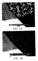
- a test pattern of 3 overlapping circles of primary colors (cyan. magenta, yellow), secondary colors (red, green blue) and tertiary color (black) inkjet printed onto an inkjet receptor medium of the present invention shows the precision of color control and pigment location on the medium.
- Fig. 2b is a photomicrograph of 50X magnification of the intersection of the red, green, black, and yellow colors of a test pattern printed on an embossed image surface having a microembossed pattern of cube comer shapes having a depth of 87 microns (87 ⁇ m) and a tip to base distance on the triangular face of the void of 175 microns (175 ⁇ m).
- the yellow color in the lower left portion of Fig. 2b is supplied by only one pigment, whereas the red and green are formed by the mixing of two primary pigments each and the black by the mixing of the three pigments.
- the clarity and precision of the lines of demarcation between adjoining colors as well as the continuity of the color within the areas of each of the colors are direct and surprising advantages of the present invention.
- the pigment particles reside beneath the nominal macroscopic surface of the inkjet receptor medium, the pigment particles are protected from abrasion that does not penetrate as deep as the location of the particles. Incidental abrasion of the graphic during graphic handling after printing is minimized.
- the shape of cavity geometry can contribute significantly to the final appearance of the image graphic because of the appearance of the image caused by presence of pigments residing in cavities 14 having different geometries to the line of sight, i.e., one can see pigment deposited on angular planar walls but not on walls parallel to the line of sight.
- the half tone printing pattern will be so refined as to align the printing pattern of the ink, drop by drop, with the embossed pattern on the medium, cavity by cavity. That would permit full justification of the printing process resembling the image displayed on a digital color monitor.
- Another benefit of the media of the present invention is the controlled rate of drying of the ink drop in each cavity. Drying can be measured as the time required before the image becomes tack free or does not smear when lightly rubbed. Typically, the image feels dry within 2 minutes and preferably within 30 seconds after imaging.
- the use of isolated cavities to minimize migration of color during drying is an advantage in the receptor medium of the invention not previously found in the art.
- inkjet images are provided by a variety of commercially available printing techniques.
- thermal inkjet printers such as DeskJet brand, PaintJet brand, Deskwriter brand, DesignJet brand, and other printers commercially available from Hewlett Packard Corporation of Palo Alto, California.
- piezo type inkjet printers such as those from Seiko-Epson, Raster Graphics, and Xerox, spray jet printers and continuous inkjet printers. Any of these commercially available printing techniques introduce the ink in a jet spray of a specific image into the medium of the present invention. Drying is much more rapid under the present invention than if the imaging layer were to be applied to a similar non-embossed media.
- the media of the present invention can be used with a variety of inkjet inks obtainable from a variety of commercial sources. It should be understood that each of these inks have different formulations, even for different colors within the same ink family. Nonlimiting sources include Minnesota Mining and Manufacturing Company, Encad Corporation, Hewlett Packard Corporation, NuKote, and the like. These inks are preferably designed to work with the inkjet printers described immediately above and in the background section above, although the specifications of the printers and the inks will have to be reviewed for appropriate drop volumes and dpi in order to further refine the usefulness of the present invention.
- Jettable materials i.e., those materials capable of passing through an inkjet printing head.
- jettable materials include adhesives, biological fluids, chemical assay reagents, pharmaceuticals, particulate dispersions, waxes, and combinations thereof.
- Media of the present invention can also be employed with non-jettable materials so long as an inkjet printing head is not needed to deposit the material on the embossed surface.
- U.S. Pat. No. 5,658,802 discloses printed arrays for DNA, immunoassay reagents or the like using arrays of electromechanical dispensers to form extremely small drops of fluid and locate them precisely on substrate surfaces in miniature arrays.
- CIRCLE pattern An internal test pattern used throughout these examples, developed to observe printing of 100%, 200% and 300% of cyan, magenta, and yellow inks, is called the CIRCLE pattern.
- a circle of 100% fill of each of the three colors is printed such that the circles overlap to produce red where the yellow and magenta circles overlap, blue where magenta and cyan overlap, and green where yellow and cyan overlap.
- all three circles overlap and 300% ink is deposited to form black.
- Several different qualitative print properties can be observed using this test pattern, including dry time, absorption capacity, bleed of one color into another, and color density.
- 3M Thermal Inkjet Media 3657-10 was removed from the finished roll with coating, adhesive, and liner intact and set against the CCP embossing mold in a hot press. Conditions which work well for both the 3657-10 and 8502 media were 1.0x10 5 kPa at 143°C, both platens, for two minutes. Thus the media was embossed after the inkjet receptor coating was applied.
- the print cartridges in the NovaJet III are Hewlett-Packard 51626A type and these were filled with 3M's cyan, magenta, yellow, and black pigmented inks (Yellow: TB 14002, Lot 01x2; Magenta: TB14003, Lot 01x2A; Cyan: TB14001, Lot 01x2; Black: TB14004, Lot 2A).
- the print test called CIRCLES is a simple pattern of the three primary colors (cyan, magenta, yellow) which overlap to form secondary colors (blue, red, green) with 200% ink and a three color (300% ink) black at the center. In addition to showing aspects of ink mixing and mudcracking, the pattern is small; this means a short carriage return time of the printer which, in turn, means that problems such as feathering, banding, and coalescence of the ink are maximized.
- Figure 1a and 1b are 50X micrographs of the yellow/red/green/black interface of these two samples respectively.
- the CUBE and PYR1 pattern were extrusion embossed on Union Carbide 7C50 (a propylene - ethylene random copolymer).
- the embossed sheets were coated with a salt/surfactant dispersion, the components of which are listed in the table below. Coating was accomplished using a #3 Mayer rod, a coating rod manufactured by RD Specialties of Webster, NY, followed by low heat drying with a heat gun.
- the coated 7C50 sheets were printed upon using an Encad NovaJet 4 equipped with 3M pigmented inks.
- the CIRCLES pattern was used to illustrate printing properties.
- embossed uncoated sheets were printed in the same manner. (A second control, coating onto a flat 7C50 sheet, could not be carried out: the resulting dried coating leaves large salt crystals and sticky puddles of surfactant. The embossed recesses allow for deposition of the material without visible or tactile changes.)
- the embossed and coated samples produced very good image quality in the test pattern. There was no feathering evident.
- the coated sample with the CUBE recesses had a dry time of less than a minute for CMY, 2-3 minutes for RGB, and 5-10 minutes for black.
- dry means the ability to withstand smearing with light finger pressure.
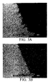
- Figure 4a shows resolution of the CIRCLE pattern generated on the coated PYR1 patterned 7C50 by the HP2500CP.
- Figure 4b is a 25X micrograph of the intersection of black, red, green , and yellow printed areas in 4a. Note that the resolution of the print is very good. Color density was also good.
- Example 3 Transparency of embossed substrates on an overhead projector
- PET copolymer Eastar 6763 from Eastman Chemicals was extrusion embossed with four patterns for comparison to an extruded, unpatterned sample of Eastar 6763 as observed as a projection onto a white background from an overhead projector.
- the first pattern, CUBE produced a projection which was as clear as the control sample.
- RECT also produced a clear projection.
- PYR 2 projected a gray image
- CCP projected a black image.
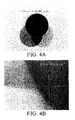
- a sample of 4 mil (0.101 ⁇ m) PET sheeting embossed with the POST pattern was passed unmodified through a Hewlett-Packard DeskJet 855Cse, to print solid areas of color in cyan, red, blue, green, purple, yellow, and magenta.
- Figure 5a is a 100X micrograph of the unprinted post sample.
- Figure 5b is the same sample after printing, showing dried cyan ink which is principally located around the base of the posts with almost no ink present in other areas.
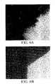
- Example 5 printing on olefin substrate with waterborne inks
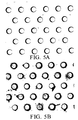
- FIG. 6a and 6b A picture of each of these printed samples is shown in Figure 6a and 6b.
- the control (smooth) 7C50 sample is shown at 100X to show the lack of ink uptake by the substrate.
- Figure 6b shows the print at the same magnification for the PYR1 embossed 7C50 sheet, which exemplifies the effect of embossing: the ink is completely retained in the cavities and thus resolution and lack of feathering, as well as the dry feel, are a direct result of printing on a microembossed substrate.
- Phase change inks from Tektronix Company of Oregon, were printed on flat and embossed PVC, 7C50 film and 40 wt% feldspar-filled 7C50.
- the CCP pattern was used.
- the Tektronix wax inks were printed using a Tektronix Phaser 300x.
- the ink printed well however, the solidified ink was very easily scratched from the surface with the fingernail: this is a major shortcoming of the wax based inks.
- Specially coated substrates are marketed by several companies which essentially provide a bumpy surface to produce mechanical adhesion.
- the embossed substrates exhibited a remarkable improvement in abrasion resistance, with no loss of color density. Particularly in the case of both the filled and unfilled 7C50 materials, resistance to fingernail scratching was almost complete; only the hardest finger pressure resulted in scratching of the ink from the surface.
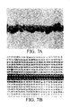
- Figure 7a and 7b shows micrographs of lines printed on plain extruded vinyl film and microembossed vinyl film.
- the microembossed structure RECT is optimized for the MIT printhead that produces 40 ⁇ m drops at 360 dpi (360 dots/2.54cm) resolution.
- Figure 7a shows that on plain vinyl film, the lines are 120 - 150 (over 300% dot gain) ⁇ m in width (this is the same line width seen on cast vinyl film also).
- the microembossed film gives line width of 50 ⁇ m (25% dot gain), the same width as the microembossed structure. This example shows that microreplication can provide precise control of dot gain.
- the RECT pattern was embossed by hot press into a coextruded film of poly(ethylene terephthalate) (PET) and Eastar 6763.
- PET poly(ethylene terephthalate)
- the film was biaxially oriented 2 X 2 prior to embossing.
- the total thickness of the oriented film was 50 ⁇ m, of which the Eastar 6763 layer was about 21 ⁇ m.
- the temperature of the press was not higher than 165°C, which is insufficient to relax the biaxially oriented PET layer. This film was used without further modification by topical coating, etc.
- the patterned sheet was subjected to a print test in an HP 855Cse desktop inkjet printer.
- 3M's CG3460 overhead transparency product was printed with the same test pattern.
- the print mode chosen was "normal"/"plain paper". This print mode instructs the printer to print at the highest possible speed.
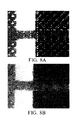
- Figure 8 shows 33X micrographs of one area of the print test pattern, to illustrate the difference between the ink uptake mechanism of the two films.
- Figure 8a shows the intersection of a red line with a blue solid area printed on the CG3460 film.
- Figure 8b shows the corresponding area of the microembossed sheet. Poor print quality due to ink beading is apparent in Figure 8a; ink beading is presumably caused by the fast print speed. Good quality prints can be obtained on CG3460 by using the "transparency" print mode. Ink beading is not apparent in Figure 8b, and the uncoated embossed sample shows good line width control and resolution of the test pattern.
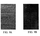
- Figure 9 further shows the benefits of microembossing in the same test print.
- Figure 9a shows a solid black printed block on the CG3460 sample without magnification;
- 9b shows the corresponding area on the RECT embossed sample.
- the black print area formed by the pigmented ink in the Hewlett Packard DeskJet 855Cse was observed to undergo severe mudcracking in the fast print mode when printed on CG3460.
- black areas look continuous, dense, and sharp.
- banding patterns which were apparent in the black and colored areas of the CG3460 sample (again presumably due to the fast printing), were absent in the microembossed sample.
Description
More specifically, polyolefins can be ethylene homopolymers or copolymers, such as "7C50" brand ethylene propylene copolymer commercially available from Union Carbide Co. of Houston, Texas, USA. Other specifically useful films include THV-500 from Dyneon LLC, plasticized poly(vinyl chloride), poly(ethylene terephthalate) copolymer Eastar 6763 from Eastman, Affinity PL 1845 from Dow Chemical, and Surlyn™ acrylic acid copolymers from DuPont.
| DEFINITION OF EMBOSSED PATTERNS | |||||||
| Shape ID | Description | # Sides at Top | CENTER-CENTER DISTANCE µm | Feature Depth µm | Wall Thickness µm | ° Wall Tilt From Normal To Surface | POST height, diameter & spacing, µm |
| CCP | Cube corner prism shaped crevice | 3 | 175 | 87 | Knife edge | 60 | - |
| CUBE | Cube shaped crevice | 4 | 80 | 75 | 5µm | <5 | - |
| RECT | Rectangular shaped crevice | 4 | 55 | 25 | 5µm | <5 | - |
| PYR1 | Truncated pyramid shaped crevice | 4 | 90 | 75 | 7µm | 12 | - |
| PYR2 | Pyramid shaped crevice | 4 | 80 | 75 | 5µm | 15 | - |
| POST | Cylinder protruding from substrate surface | - | - | - | - | <5 | 400 (H) 100 (D) 140 (spacing) |
| 7C50 Coating Formulation | |
| Al2(SO4)3 | 6 wt% |
| Dioctyl sulfosuccinate (DOSS) | 7 wt% |
| Silwet L7607 | 1 wt% |
| Surfynol 204 | 2 wt% |
| Ethanol | 25 wt% |
| Water | 59 wt% |
Claims (14)
- A patterned inkjet receptor medium comprising a sheet having an embossed surface as one major surface thereof and a material deposited on the embossed surface, wherein the sheet is nonporous and wherein each element of the embossed surface is a cavity enclosed by walls on all sides and has a capacity of at least 20 pL.
- The medium of Claim 1, wherein the embossed surface comprises a repeated pattern over the area of the major surface, and wherein the sheet is transparent, translucent, or opaque, wherein the sheet is clear or tinted, and wherein the sheet is optically transmissive, optically reflective, or optically retroreflective.
- The medium of Claim 1, wherein the embossed surface is a microembossed pattern.
- The medium of any of Claims 1-3, wherein the embossed surface comprises cavities completely enclosed by walls on all sides and packed closely together such that (1) thickness of the wall tops is 10 µm or less, (2) crevice volume is commensurate with 100 to 300% ink, and (3) the number of crevices per inch is equal to or greater than the number of dots per inch (dpi) of a targeted printer.
- The medium of Claim 1, wherein the embossed surface has a topography to protect material from abrasion from items contacting the embossed surface, that on a macroscopic level, constitute the outermost surface of the medium.
- The medium of any of Claims 1-5, wherein the embossed surface has a pattern of cavities to control dot gain of inkjet ink.
- The medium of any of Claims 1-5, wherein the embossed surface has a pattern of cavities wherein volume of any one cavity is sufficient enough to anticipate placement of at least two drops of ink, and wherein aspect ratio of a cavity can range from 0.3 to 2, and wherein the pattern comprises cube comer prism, cube, pyramid, truncated pyramid, or hemi-ellipse.
- The medium of Claim 7, wherein the volume of a cavity can range from 20 to 1000 pL.
- The medium of Claim 7, wherein one cavity ranges from being cubic-shaped and having a depth ranging from 25 to 75µm and wherein walls between cavities are at 0° tilt from normal to being hemi-spherical and has a depth ranging from 35 to 70µm.
- The medium of any of Claims 2-5, wherein the sheet is a polymeric film selected from the group consisting of polyolefins, poly(vinyl chloride), copolymers of ethylene with vinyl acetate or vinyl alcohol, copolymers and terpolymers of hexafluoropropylene and surface modified versions thereof, poly(ethylene terephthalate) and copolymers thereof, polyurethanes, polyimides, acrylics, and filled versions thereof, wherein the filled versions employ fillers selected from the group consisting of silicates, aluminates, feldspar, talc, calcium carbonate, and titanium dioxide.
- The medium of any one of Claims 1-10, further comprising an adhesive layer on a major surface opposite the embossed surface.
- The medium of Claim 1, wherein the material is jettable and selected from the group consisting of inks, adhesives, biological fluids, pharmaceuticals, chemical assay reagents, particulate dispersions, waxes, and combinations thereof.
- A method of producing an image, comprising the step of printing a jettable material through an inkjet printing head onto an embossed surface of a receptor medium comprising a sheet having an embossed surface as one major surface wherein the sheet is nonporous and wherein each element of the embossed surface is a cavity enclosed by walls on all sides and has a capacity of at least 20 pL.
- The method of Claim 13, wherein the material is selected from the group consisting of inks, adhesives, biological fluids, pharmaceuticals, chemical assay reagents, particulate dispersions, waxes, and combinations thereof.
Applications Claiming Priority (3)
| Application Number | Priority Date | Filing Date | Title |
|---|---|---|---|
| US6966598A | 1998-04-29 | 1998-04-29 | |
| US69665 | 1998-04-29 | ||
| PCT/US1999/008037 WO1999055537A1 (en) | 1998-04-29 | 1999-04-13 | Receptor sheet for inkjet printing having an embossed surface |
Publications (2)
| Publication Number | Publication Date |
|---|---|
| EP1089880A1 EP1089880A1 (en) | 2001-04-11 |
| EP1089880B1 true EP1089880B1 (en) | 2004-02-11 |
Family
ID=22090453
Family Applications (1)
| Application Number | Title | Priority Date | Filing Date |
|---|---|---|---|
| EP99917444A Expired - Lifetime EP1089880B1 (en) | 1998-04-29 | 1999-04-13 | Receptor sheet for inkjet printing having an embossed surface |
Country Status (11)
| Country | Link |
|---|---|
| US (1) | US6386699B1 (en) |
| EP (1) | EP1089880B1 (en) |
| JP (1) | JP2002512911A (en) |
| KR (1) | KR100615913B1 (en) |
| CN (1) | CN1173835C (en) |
| AU (1) | AU742184B2 (en) |
| BR (1) | BR9910015A (en) |
| CA (1) | CA2329011A1 (en) |
| DE (1) | DE69914754T2 (en) |
| NZ (1) | NZ507729A (en) |
| WO (1) | WO1999055537A1 (en) |
Cited By (1)
| Publication number | Priority date | Publication date | Assignee | Title |
|---|---|---|---|---|
| WO2017127049A1 (en) * | 2016-01-19 | 2017-07-27 | Hewlett-Packard Development Company, L.P. | Embossed print media |
Families Citing this family (70)
| Publication number | Priority date | Publication date | Assignee | Title |
|---|---|---|---|---|
| AU5452500A (en) * | 1999-06-01 | 2000-12-18 | 3M Innovative Properties Company | Random microembossed receptor media |
| CN1170693C (en) | 1999-06-01 | 2004-10-13 | 3M创新有限公司 | Optically transmissive microembossed receptor media |
| US6667080B2 (en) * | 2000-02-04 | 2003-12-23 | Canon Kabushiki Kaisha | Recording medium, production process and heat-treatment process of the recording medium, and recording apparatus |
| AU4905601A (en) * | 2000-02-08 | 2001-08-20 | 3M Innovative Properties Company | Improved media for cold image transfer |
| WO2001058697A2 (en) | 2000-02-08 | 2001-08-16 | 3M Innovative Properties Company | Ink fixing materials and methods of fixing ink |
| BR0015893A (en) * | 2000-06-09 | 2003-07-01 | 3M Innovative Properties Co | Image-retaining laminate assembly, and methods of forming an image-retaining laminate and medium |
| US6555213B1 (en) * | 2000-06-09 | 2003-04-29 | 3M Innovative Properties Company | Polypropylene card construction |
| US20020052439A1 (en) | 2000-08-08 | 2002-05-02 | 3M Innovative Properties Company | Ink receptive compositions and articles for image transfer |
| US6874421B2 (en) | 2001-04-20 | 2005-04-05 | 3M Innovative Properties Company | Ink jet transfer printing process |
| WO2003035406A1 (en) * | 2001-10-22 | 2003-05-01 | 3M Innovative Properties Company | Transfer printing process and transfer printing sheet |
| US20030082352A1 (en) | 2001-10-29 | 2003-05-01 | Eastman Kodak Company | Receiver media for high quality ink jet printing |
| US6638693B2 (en) | 2001-10-29 | 2003-10-28 | Eastman Kodak Company | Process for making media for high quality ink jet printing |
| US20030219552A1 (en) * | 2002-02-19 | 2003-11-27 | Graham Paul D. | Polyvinylpyridine image receptive material |
| US7255909B2 (en) * | 2002-02-19 | 2007-08-14 | 3M Innovative Properties Company | Security laminate |
| US6978896B2 (en) | 2002-04-11 | 2005-12-27 | 3M Innovative Properties Company | Method of making retrochromic beads and kit thereof |
| US7036944B2 (en) | 2002-04-11 | 2006-05-02 | 3M Innovative Properties Company | Retrochromic articles |
| US20030235678A1 (en) * | 2002-06-25 | 2003-12-25 | Graham Paul D. | Complex microstructure film |
| US20030235677A1 (en) | 2002-06-25 | 2003-12-25 | 3M Innovative Properties Company | Complex microstructure film |
| FR2843911B1 (en) * | 2002-08-30 | 2005-09-02 | Bretonne D Etiquettes Soc | METHOD AND DEVICE FOR MANUFACTURING A FILM HAVING BRAILLE TYPE RELIEF INFORMATION AND FOR MAKING LABELS |
| US6848795B2 (en) * | 2002-10-24 | 2005-02-01 | Eastman Kodak Company | Increased contrast overhead projection films |
| US7678443B2 (en) | 2003-05-16 | 2010-03-16 | 3M Innovative Properties Company | Complex microstructure film |
| US20040229018A1 (en) * | 2003-05-16 | 2004-11-18 | Graham Paul D | Complex microstructure film |
| US7648744B2 (en) * | 2004-08-06 | 2010-01-19 | 3M Innovative Properties Company | Tamper-indicating printable sheet for securing documents of value and methods of making the same |
| US7658980B2 (en) * | 2004-08-06 | 2010-02-09 | 3M Innovative Properties Company | Tamper-indicating printable sheet for securing documents of value and methods of making the same |
| US7404997B2 (en) * | 2004-09-02 | 2008-07-29 | 3M Innovative Properties Company | Substrates with multiple images |
| US8114502B2 (en) | 2004-09-02 | 2012-02-14 | 3M Innovative Properties Company | Substrates with multiple images |
| US20060046159A1 (en) * | 2004-09-02 | 2006-03-02 | Emslander Jeffrey O | Methods of manufacturing substrates with multiple images |
| US7446940B2 (en) * | 2004-09-02 | 2008-11-04 | 3M Innovative Properties Company | Substrates with multiple images and methods of use |
| US7416776B2 (en) * | 2004-09-02 | 2008-08-26 | 3M Innovative Properties Company | Substrates with multiple images |
| US7195360B2 (en) * | 2004-12-28 | 2007-03-27 | 3M Innovative Properties Company | Prismatic retroreflective article and method |
| KR20130008643A (en) * | 2004-12-28 | 2013-01-22 | 쓰리엠 이노베이티브 프로퍼티즈 컴파니 | Prismatic retroreflective article with fluorine- or silicon-containing prisms |
| US7594976B2 (en) * | 2005-05-13 | 2009-09-29 | 3M Innovative Properties Company | Methods of manufacturing substrates |
| TWI338189B (en) * | 2006-01-13 | 2011-03-01 | Hon Hai Prec Ind Co Ltd | Substrate structure and method of manufacturing thin film pattern layer using the same |
| US8513322B2 (en) * | 2007-05-31 | 2013-08-20 | 3M Innovative Properties Company | Polymeric beads and methods of making polymeric beads |
| US7547105B2 (en) * | 2007-07-16 | 2009-06-16 | 3M Innovative Properties Company | Prismatic retroreflective article with cross-linked image layer and method of making same |
| TW200934449A (en) | 2007-12-12 | 2009-08-16 | 3M Innovative Properties Co | Hydrophilic gel materials and methods of making |
| US8318282B2 (en) * | 2007-12-12 | 2012-11-27 | 3M Innovative Properties Company | Microstructured antimicrobial film |
| JP2011508265A (en) | 2007-12-21 | 2011-03-10 | スリーエム イノベイティブ プロパティズ カンパニー | Retroreflective article and retroreflective element comprising a spherical core and two concentric optical interference layers |
| CN101590775A (en) * | 2008-05-28 | 2009-12-02 | Icf科技有限公司 | Surface treatment method of plastic components |
| JP5319769B2 (en) * | 2008-06-30 | 2013-10-16 | スリーエム イノベイティブ プロパティズ カンパニー | Method for forming a patterned substrate |
| KR20110049777A (en) * | 2008-06-30 | 2011-05-12 | 쓰리엠 이노베이티브 프로퍼티즈 컴파니 | Method of forming a microstructure |
| WO2010080236A1 (en) * | 2008-12-19 | 2010-07-15 | 3M Innovative Properties Company | System and method for processing samples |
| CN102301220B (en) | 2008-12-19 | 2014-06-25 | 3M创新有限公司 | System And Method For Concentrating Samples |
| DE102009005132A1 (en) * | 2009-01-15 | 2010-07-22 | Sebastian Gepp | Method for producing structures on substrate surface in micrometer range by applying printing techniques, involves filling structures with functional ink by nozzles |
| EP2404739A1 (en) | 2010-07-09 | 2012-01-11 | 3M Innovative Properties Co. | Durable hyrophobic structured surface |
| EP2632613B1 (en) | 2010-10-28 | 2017-08-30 | 3M Innovative Properties Company | Engineered surfaces for reducing bacterial adhesion |
| US8530021B2 (en) | 2011-03-08 | 2013-09-10 | 3M Innovative Properties Company | Microstructured tape |
| WO2013003373A1 (en) | 2011-06-27 | 2013-01-03 | 3M Innovative Properties Company | Microstructured surfaces for reducing bacterial adhesion |
| JP2014518394A (en) | 2011-06-30 | 2014-07-28 | スリーエム イノベイティブ プロパティズ カンパニー | System and method for detecting a target analyte in a sample using a microstructured surface |
| CN103620373B (en) | 2011-06-30 | 2017-07-07 | 3M创新有限公司 | Using the method for analyte of interest in filter and microstructured surface detection sample |
| US10102778B2 (en) * | 2012-12-13 | 2018-10-16 | Shinichiro Kakuda | Information writable film and a sample storage body |
| WO2014189716A1 (en) | 2013-05-21 | 2014-11-27 | 3M Innovative Properties Company | Nanostructured spore carrier |
| EP3083055A1 (en) | 2013-12-20 | 2016-10-26 | 3M Innovative Properties Company | Systems and methods for sample concentration and detection using a separation liquid |
| WO2015095142A2 (en) | 2013-12-20 | 2015-06-25 | 3M Innovative Properties Company | Systems and methods for sample concentration and detection |
| BR112017006724A2 (en) | 2014-10-03 | 2017-12-19 | 3M Innovative Properties Co | methods for managing incident light scattering and articles created from them |
| WO2017048276A1 (en) * | 2015-09-18 | 2017-03-23 | Hewlett-Packard Development Company, L.P. | Leveling compositions |
| US10618335B2 (en) * | 2015-12-15 | 2020-04-14 | Hewlett-Packard Development Company, L.P. | Embossed print media |
| JP6772496B2 (en) * | 2016-03-17 | 2020-10-21 | 凸版印刷株式会社 | How to make foam wallpaper |
| BR112018072385B1 (en) * | 2016-07-20 | 2022-03-03 | Hewlett-Packard Development Company, L.P. | Methods of printing a three-dimensional object and non-transient machine-readable storage medium |
| EP3551991A1 (en) | 2016-12-09 | 2019-10-16 | 3M Innovative Properties Company | Systems and methods for rapid detection of an analyte of interest |
| JP2022545424A (en) | 2019-08-20 | 2022-10-27 | スリーエム イノベイティブ プロパティズ カンパニー | Microstructured Surfaces, Articles, and Methods with Enhanced Microbial Removal During Cleaning |
| US11766822B2 (en) | 2019-08-20 | 2023-09-26 | 3M Innovative Properties Company | Microstructured surface with increased microorganism removal when cleaned, articles and methods |
| WO2021033151A1 (en) | 2019-08-20 | 2021-02-25 | 3M Innovative Properties Company | Medical articles with microstructured surface having increased microorganism removal when cleaned and methods thereof |
| EP4153060A1 (en) | 2020-05-20 | 2023-03-29 | 3M Innovative Properties Company | Medical articles with microstructured surface |
| JP2023553925A (en) | 2020-12-11 | 2023-12-26 | スリーエム イノベイティブ プロパティズ カンパニー | Methods and articles for thermoforming films with structured surfaces |
| WO2022162528A1 (en) | 2021-01-28 | 2022-08-04 | 3M Innovative Properties Company | Microstructured surface with increased microorganism removal when cleaned, articles and methods |
| US20240099815A1 (en) | 2021-02-23 | 2024-03-28 | 3M Innovative Properties Company | Medical articles with microstructured surface having increased microorganism removal when cleaned and methods thereof |
| WO2023042072A1 (en) | 2021-09-14 | 2023-03-23 | 3M Innovative Properties Company | Articles including a microstructured curved surface and methods of making same |
| WO2023105372A1 (en) | 2021-12-07 | 2023-06-15 | 3M Innovative Properties Company | Microstructured surface and articles with lower visibilty of scratches and methods |
| KR102442915B1 (en) * | 2022-01-25 | 2022-09-15 | 주식회사 에코월드팜 | Smart print bed for tissue constructs under biomimetic control |
Family Cites Families (65)
| Publication number | Priority date | Publication date | Assignee | Title |
|---|---|---|---|---|
| US3957724A (en) | 1973-12-11 | 1976-05-18 | Minnesota Mining And Manufacturing Company | Stratum having release properties and method of making |
| DE2651427A1 (en) | 1976-11-11 | 1978-05-18 | Agfa Gevaert Ag | Electrophotographic copying onto sheet with fine surface indentations - giving high resolution of final image obtd. by toner transfer |
| US4145112A (en) | 1977-07-14 | 1979-03-20 | Minnesota Mining And Manufacturing Company | Low-profile raised retroreflective sheeting |
| US4576850A (en) | 1978-07-20 | 1986-03-18 | Minnesota Mining And Manufacturing Company | Shaped plastic articles having replicated microstructure surfaces |
| US4379804A (en) | 1979-04-09 | 1983-04-12 | Minnesota Mining And Manufacturing Company | Liquid sorbent materials |
| US4313988A (en) | 1980-02-25 | 1982-02-02 | Minnesota Mining And Manufacturing Company | Epoxypolysiloxane release coatings for adhesive materials |
| US4567073A (en) | 1982-07-02 | 1986-01-28 | Minnesota Mining And Manufacturing Company | Composite low surface energy liner of perfluoropolyether |
| JPS6058458B2 (en) | 1982-08-12 | 1985-12-20 | コニカ株式会社 | Radiographic image forming method |
| US4605592A (en) | 1982-08-19 | 1986-08-12 | Minnesota Mining And Manufacturing Company | Composite decorative article |
| US4588258A (en) | 1983-09-12 | 1986-05-13 | Minnesota Mining And Manufacturing Company | Cube-corner retroreflective articles having wide angularity in multiple viewing planes |
| US4614667A (en) | 1984-05-21 | 1986-09-30 | Minnesota Mining And Manufacturing Company | Composite low surface energy liner of perfluoropolyether |
| JPS6186971A (en) * | 1984-10-04 | 1986-05-02 | Toyoda Gosei Co Ltd | Formation of decorative layer to product having impression |
| US4649064A (en) | 1986-03-10 | 1987-03-10 | Eastman Kodak Company | Rapid-drying recording element for liquid ink marking |
| US4904519A (en) | 1986-05-12 | 1990-02-27 | Minnesota Mining And Manufacturing Company | Ink-receptive sheet |
| US5214119A (en) | 1986-06-20 | 1993-05-25 | Minnesota Mining And Manufacturing Company | Block copolymer, method of making the same, dimaine precursors of the same, method of making such diamines and end products comprising the block copolymer |
| US4861644A (en) | 1987-04-24 | 1989-08-29 | Ppg Industries, Inc. | Printed microporous material |
| US4935307A (en) | 1988-10-21 | 1990-06-19 | Minnesota Mining And Manufacturing Company | Transparent coatings for graphics applications |
| US5045386A (en) | 1989-02-01 | 1991-09-03 | Minnesota Mining And Manufacturing Company | Pressure-sensitive film composite having improved adhesion to plasticized vinyl substrates |
| US5175030A (en) | 1989-02-10 | 1992-12-29 | Minnesota Mining And Manufacturing Company | Microstructure-bearing composite plastic articles and method of making |
| US5183597A (en) | 1989-02-10 | 1993-02-02 | Minnesota Mining And Manufacturing Company | Method of molding microstructure bearing composite plastic articles |
| JP2513902B2 (en) | 1989-06-02 | 1996-07-10 | 東レ株式会社 | Surface porous film |
| US5023129A (en) | 1989-07-06 | 1991-06-11 | E. I. Du Pont De Nemours And Company | Element as a receptor for nonimpact printing |
| US5202190A (en) | 1989-08-14 | 1993-04-13 | Minnesota Mining And Manufacturing Company | Method of making vinyl-silicone copolymers using mercapto functional silicone chain-transfer agents and release coatings made therewith |
| US4903041A (en) | 1989-08-14 | 1990-02-20 | Eastman Kodak Company | Transparent image-recording elements comprising vinyl pyrrolidone polymers and polyesters |
| US5213873A (en) | 1989-10-20 | 1993-05-25 | Oji Paper Co., Ltd. | Aqueous ink-jet recording sheet |
| US5141790A (en) | 1989-11-20 | 1992-08-25 | Minnesota Mining And Manufacturing Company | Repositionable pressure-sensitive adhesive tape |
| US5229207A (en) | 1990-04-24 | 1993-07-20 | Minnesota Mining And Manufacturing Company | Film composite having repositionable adhesive by which it can become permanently bonded to a plasticized substrate |
| US5192548A (en) | 1990-04-30 | 1993-03-09 | Riker Laboratoires, Inc. | Device |
| DE4024544A1 (en) | 1990-08-02 | 1992-02-06 | Boehringer Mannheim Gmbh | ANALYZING ELEMENT AND METHOD FOR THE PRODUCTION THEREOF |
| US5138488A (en) | 1990-09-10 | 1992-08-11 | Minnesota Mining And Manufacturing Company | Retroreflective material with improved angularity |
| US5208092A (en) | 1990-10-24 | 1993-05-04 | Minnesota Mining And Manufacturing Company | Transparent liquid absorbent materials for use as ink-receptive layers |
| KR100216669B1 (en) | 1990-10-30 | 1999-09-01 | 스프레이그 로버트 월터 | Articles having a hydrophilic polymeric shell and method for preparing the same |
| CA2095337A1 (en) * | 1990-11-01 | 1992-05-02 | John J. Fitch | Method of forming a coated sheet which wicks away oil and product thereof |
| US5084338A (en) | 1990-12-03 | 1992-01-28 | Eastman Kodak Company | Transparent image-recording elements containing ink-receptive layers |
| DK0570515T3 (en) | 1991-02-06 | 1996-10-07 | Minnesota Mining & Mfg | Positionable adhesive system with high shear strength |
| US5141797A (en) | 1991-06-06 | 1992-08-25 | E. I. Du Pont De Nemours And Company | Ink jet paper having crosslinked binder |
| JP3213630B2 (en) | 1991-07-25 | 2001-10-02 | 三菱製紙株式会社 | Inkjet recording sheet |
| KR100219954B1 (en) | 1991-09-12 | 1999-09-01 | 스프레이그 로버트 월터 | Patterned pressure sensitive adhesive transfer tape |
| US5219462A (en) | 1992-01-13 | 1993-06-15 | Minnesota Mining And Manufacturing Company | Abrasive article having abrasive composite members positioned in recesses |
| US5437754A (en) | 1992-01-13 | 1995-08-01 | Minnesota Mining And Manufacturing Company | Abrasive article having precise lateral spacing between abrasive composite members |
| US5271765A (en) | 1992-02-03 | 1993-12-21 | E. I. Du Pont De Nemours And Company | Aqueous cationic dye-based ink jet inks |
| US5212008A (en) | 1992-04-01 | 1993-05-18 | Xerox Corporation | Coated recording sheets |
| US5589269A (en) | 1993-03-12 | 1996-12-31 | Minnesota Mining And Manufacturing Company | Ink receptive sheet |
| US5342688A (en) | 1993-03-12 | 1994-08-30 | Minnesota Mining And Manufacturing Company | Ink-receptive sheet |
| US5354813A (en) | 1993-03-12 | 1994-10-11 | Minnesota Mining And Manufacturing Company | Polymeric mordants for dyes and the like |
| JP3039752B2 (en) | 1993-09-24 | 2000-05-08 | キヤノン株式会社 | Marking sheet, marking sheet and manufacturing method thereof |
| JP3282761B2 (en) * | 1993-09-27 | 2002-05-20 | 王子製紙株式会社 | Inkjet recording paper |
| US5450235A (en) | 1993-10-20 | 1995-09-12 | Minnesota Mining And Manufacturing Company | Flexible cube-corner retroreflective sheeting |
| JPH082096A (en) * | 1994-06-23 | 1996-01-09 | New Oji Paper Co Ltd | Ink jet recording paper |
| US5747148A (en) | 1994-09-12 | 1998-05-05 | Minnesota Mining And Manufacturing Company | Ink jet printing sheet |
| EP0822881B1 (en) | 1995-04-26 | 2009-08-12 | Minnesota Mining And Manufacturing Company | Laser imaging ablation method |
| US5702559A (en) | 1995-07-13 | 1997-12-30 | B&H Manufacturing Company, Inc. | Method and apparatus for applying a tactilely distinguishable marking on an article |
| US5658802A (en) | 1995-09-07 | 1997-08-19 | Microfab Technologies, Inc. | Method and apparatus for making miniaturized diagnostic arrays |
| JP3973709B2 (en) | 1995-09-22 | 2007-09-12 | 王子製紙株式会社 | Molded inkjet recording paper |
| JPH09127327A (en) | 1995-11-02 | 1997-05-16 | Asahi Glass Co Ltd | Production of color filter and liquid crystal display element using that |
| IL116123A (en) | 1995-11-23 | 1999-07-14 | Scitex Corp Ltd | System and method for printing |
| JPH09175004A (en) | 1995-12-22 | 1997-07-08 | Kimoto & Co Ltd | Ink-jet recording material |
| US5605750A (en) | 1995-12-29 | 1997-02-25 | Eastman Kodak Company | Microporous ink-jet recording elements |
| AU2006197A (en) | 1996-03-12 | 1997-10-01 | Minnesota Mining And Manufacturing Company | Inkjet recording medium |
| US5756188A (en) * | 1996-09-26 | 1998-05-26 | Eastman Kodak Company | Image-receiving laminate for ID card stock |
| US5756183A (en) | 1996-12-13 | 1998-05-26 | Foilmark Manufacturing Corporation | Microembossed paper, microembossable coating for paper substrates and a process for microembossing paper substrates |
| US6197397B1 (en) | 1996-12-31 | 2001-03-06 | 3M Innovative Properties Company | Adhesives having a microreplicated topography and methods of making and using same |
| KR20010005995A (en) | 1997-04-04 | 2001-01-15 | 스프레이그 로버트 월터 | Continuous fluid-coating flow chemical alteration process |
| US5965243A (en) | 1997-04-04 | 1999-10-12 | 3M Innovative Properties Company | Electrostatic receptors having release layers with texture and means for providing such receptors |
| US6203885B1 (en) | 1998-06-18 | 2001-03-20 | 3M Innovative Properties Company | Cling films having a microreplicated topography and methods of making and using same |
-
1999
- 1999-04-13 CA CA002329011A patent/CA2329011A1/en not_active Abandoned
- 1999-04-13 EP EP99917444A patent/EP1089880B1/en not_active Expired - Lifetime
- 1999-04-13 CN CNB998080322A patent/CN1173835C/en not_active Expired - Fee Related
- 1999-04-13 KR KR1020007012072A patent/KR100615913B1/en not_active IP Right Cessation
- 1999-04-13 AU AU35566/99A patent/AU742184B2/en not_active Ceased
- 1999-04-13 JP JP2000545714A patent/JP2002512911A/en not_active Withdrawn
- 1999-04-13 NZ NZ507729A patent/NZ507729A/en unknown
- 1999-04-13 DE DE69914754T patent/DE69914754T2/en not_active Expired - Fee Related
- 1999-04-13 WO PCT/US1999/008037 patent/WO1999055537A1/en active IP Right Grant
- 1999-04-13 BR BR9910015-0A patent/BR9910015A/en not_active Application Discontinuation
-
2000
- 2000-11-15 US US09/713,610 patent/US6386699B1/en not_active Expired - Fee Related
Cited By (1)
| Publication number | Priority date | Publication date | Assignee | Title |
|---|---|---|---|---|
| WO2017127049A1 (en) * | 2016-01-19 | 2017-07-27 | Hewlett-Packard Development Company, L.P. | Embossed print media |
Also Published As
| Publication number | Publication date |
|---|---|
| DE69914754D1 (en) | 2004-03-18 |
| DE69914754T2 (en) | 2004-12-09 |
| US6386699B1 (en) | 2002-05-14 |
| AU742184B2 (en) | 2001-12-20 |
| WO1999055537A1 (en) | 1999-11-04 |
| CN1173835C (en) | 2004-11-03 |
| NZ507729A (en) | 2003-05-30 |
| KR100615913B1 (en) | 2006-08-28 |
| BR9910015A (en) | 2001-01-09 |
| CN1307524A (en) | 2001-08-08 |
| AU3556699A (en) | 1999-11-16 |
| CA2329011A1 (en) | 1999-11-04 |
| EP1089880A1 (en) | 2001-04-11 |
| KR20010043159A (en) | 2001-05-25 |
| JP2002512911A (en) | 2002-05-08 |
Similar Documents
| Publication | Publication Date | Title |
|---|---|---|
| EP1089880B1 (en) | Receptor sheet for inkjet printing having an embossed surface | |
| EP1189758B1 (en) | Random microembossed receptor media | |
| EP1189757B1 (en) | Optically transmissive microembossed receptor media | |
| KR100550370B1 (en) | Coated microporous inkjet receptive media and method for controlling dot diameter | |
| EP1263605B1 (en) | Improved methods for cold image transfer | |
| EP0996548B1 (en) | Ink-jet printable microporous film | |
| EP1289743A1 (en) | Materials and methods for creating waterproof, durable aqueous inkjet receptive media | |
| EP0864438A1 (en) | Recording material for the ink-jet process | |
| KR19990087703A (en) | Inkjet recording media | |
| JPH09109544A (en) | Recording sheet for ink jet | |
| MXPA98003460A (en) | Sheet to print by jeting it |
Legal Events
| Date | Code | Title | Description |
|---|---|---|---|
| PUAI | Public reference made under article 153(3) epc to a published international application that has entered the european phase |
Free format text: ORIGINAL CODE: 0009012 |
|
| 17P | Request for examination filed |
Effective date: 20001122 |
|
| AK | Designated contracting states |
Kind code of ref document: A1 Designated state(s): CH DE ES FR GB IT LI NL SE |
|
| 17Q | First examination report despatched |
Effective date: 20010529 |
|
| GRAH | Despatch of communication of intention to grant a patent |
Free format text: ORIGINAL CODE: EPIDOS IGRA |
|
| GRAS | Grant fee paid |
Free format text: ORIGINAL CODE: EPIDOSNIGR3 |
|
| GRAA | (expected) grant |
Free format text: ORIGINAL CODE: 0009210 |
|
| AK | Designated contracting states |
Kind code of ref document: B1 Designated state(s): CH DE ES FR GB IT LI NL SE |
|
| PG25 | Lapsed in a contracting state [announced via postgrant information from national office to epo] |
Ref country code: LI Free format text: LAPSE BECAUSE OF FAILURE TO SUBMIT A TRANSLATION OF THE DESCRIPTION OR TO PAY THE FEE WITHIN THE PRESCRIBED TIME-LIMIT Effective date: 20040211 Ref country code: ES Free format text: LAPSE BECAUSE OF FAILURE TO SUBMIT A TRANSLATION OF THE DESCRIPTION OR TO PAY THE FEE WITHIN THE PRESCRIBED TIME-LIMIT Effective date: 20040211 Ref country code: CH Free format text: LAPSE BECAUSE OF FAILURE TO SUBMIT A TRANSLATION OF THE DESCRIPTION OR TO PAY THE FEE WITHIN THE PRESCRIBED TIME-LIMIT Effective date: 20040211 |
|
| REG | Reference to a national code |
Ref country code: GB Ref legal event code: FG4D |
|
| REG | Reference to a national code |
Ref country code: CH Ref legal event code: EP |
|
| REF | Corresponds to: |
Ref document number: 69914754 Country of ref document: DE Date of ref document: 20040318 Kind code of ref document: P |
|
| PG25 | Lapsed in a contracting state [announced via postgrant information from national office to epo] |
Ref country code: SE Free format text: LAPSE BECAUSE OF FAILURE TO SUBMIT A TRANSLATION OF THE DESCRIPTION OR TO PAY THE FEE WITHIN THE PRESCRIBED TIME-LIMIT Effective date: 20040511 |
|
| REG | Reference to a national code |
Ref country code: CH Ref legal event code: PL |
|
| ET | Fr: translation filed | ||
| PLBE | No opposition filed within time limit |
Free format text: ORIGINAL CODE: 0009261 |
|
| STAA | Information on the status of an ep patent application or granted ep patent |
Free format text: STATUS: NO OPPOSITION FILED WITHIN TIME LIMIT |
|
| 26N | No opposition filed |
Effective date: 20041112 |
|
| PGFP | Annual fee paid to national office [announced via postgrant information from national office to epo] |
Ref country code: FR Payment date: 20060417 Year of fee payment: 8 |
|
| PGFP | Annual fee paid to national office [announced via postgrant information from national office to epo] |
Ref country code: GB Payment date: 20060424 Year of fee payment: 8 |
|
| PGFP | Annual fee paid to national office [announced via postgrant information from national office to epo] |
Ref country code: IT Payment date: 20060430 Year of fee payment: 8 |
|
| PGFP | Annual fee paid to national office [announced via postgrant information from national office to epo] |
Ref country code: NL Payment date: 20060517 Year of fee payment: 8 |
|
| PGFP | Annual fee paid to national office [announced via postgrant information from national office to epo] |
Ref country code: DE Payment date: 20060531 Year of fee payment: 8 |
|
| GBPC | Gb: european patent ceased through non-payment of renewal fee |
Effective date: 20070413 |
|
| NLV4 | Nl: lapsed or anulled due to non-payment of the annual fee |
Effective date: 20071101 |
|
| PG25 | Lapsed in a contracting state [announced via postgrant information from national office to epo] |
Ref country code: NL Free format text: LAPSE BECAUSE OF NON-PAYMENT OF DUE FEES Effective date: 20071101 Ref country code: DE Free format text: LAPSE BECAUSE OF NON-PAYMENT OF DUE FEES Effective date: 20071101 |
|
| PG25 | Lapsed in a contracting state [announced via postgrant information from national office to epo] |
Ref country code: GB Free format text: LAPSE BECAUSE OF NON-PAYMENT OF DUE FEES Effective date: 20070413 |
|
| PG25 | Lapsed in a contracting state [announced via postgrant information from national office to epo] |
Ref country code: FR Free format text: LAPSE BECAUSE OF NON-PAYMENT OF DUE FEES Effective date: 20070430 |
|
| PG25 | Lapsed in a contracting state [announced via postgrant information from national office to epo] |
Ref country code: IT Free format text: LAPSE BECAUSE OF NON-PAYMENT OF DUE FEES Effective date: 20070413 |