EP1091186A2 - Method and apparatus for calibrating a non-contact gauging sensor with respect to an external coordinate system - Google Patents
Method and apparatus for calibrating a non-contact gauging sensor with respect to an external coordinate system Download PDFInfo
- Publication number
- EP1091186A2 EP1091186A2 EP00121738A EP00121738A EP1091186A2 EP 1091186 A2 EP1091186 A2 EP 1091186A2 EP 00121738 A EP00121738 A EP 00121738A EP 00121738 A EP00121738 A EP 00121738A EP 1091186 A2 EP1091186 A2 EP 1091186A2
- Authority
- EP
- European Patent Office
- Prior art keywords
- target
- sensor
- calibration
- reference frame
- calibration device
- Prior art date
- Legal status (The legal status is an assumption and is not a legal conclusion. Google has not performed a legal analysis and makes no representation as to the accuracy of the status listed.)
- Withdrawn
Links
Images


Classifications
-
- G—PHYSICS
- G01—MEASURING; TESTING
- G01B—MEASURING LENGTH, THICKNESS OR SIMILAR LINEAR DIMENSIONS; MEASURING ANGLES; MEASURING AREAS; MEASURING IRREGULARITIES OF SURFACES OR CONTOURS
- G01B11/00—Measuring arrangements characterised by the use of optical techniques
- G01B11/002—Measuring arrangements characterised by the use of optical techniques for measuring two or more coordinates
-
- G—PHYSICS
- G01—MEASURING; TESTING
- G01B—MEASURING LENGTH, THICKNESS OR SIMILAR LINEAR DIMENSIONS; MEASURING ANGLES; MEASURING AREAS; MEASURING IRREGULARITIES OF SURFACES OR CONTOURS
- G01B21/00—Measuring arrangements or details thereof, where the measuring technique is not covered by the other groups of this subclass, unspecified or not relevant
- G01B21/02—Measuring arrangements or details thereof, where the measuring technique is not covered by the other groups of this subclass, unspecified or not relevant for measuring length, width, or thickness
- G01B21/04—Measuring arrangements or details thereof, where the measuring technique is not covered by the other groups of this subclass, unspecified or not relevant for measuring length, width, or thickness by measuring coordinates of points
- G01B21/042—Calibration or calibration artifacts
Definitions
- the present invention relates generally to non-contact gauging systems. More particularly, the invention relates to an apparatus system and method for calibrating non-contact gauging systems.
- Achieving high quality manufactured parts requires highly accurate, tightly calibrated machine vision sensors. Not only must a sensor have a suitable resolution to discern a manufactured feature of interest, the sensor must be accurately calibrated to a known frame of reference so that the feature of interest may be related to other features on the workpiece. Without accurate calibration, even the most sensitive, high resolution sensor will fail to produce high quality results.
- non-contact sensors such as optical sensors
- the workpiece is placed at a predetermined, fixed location within the station, allowing various predetermined features of the workpiece to be examined by the sensors.
- all of the sensors are properly positioned and should be carefully calibrated with respect to some common fixed frame of reference, such as a common reference frame on the workpiece or at the workstation.
- Proper sensor positioning, alignment and calibration can present significant time and labor requirements.
- the entire manufacturing assembly line may need to be shut down and the workstation cleared, so that the sensor may be positioned, aligned and recalibrated. In some instances this entails placing a highly accurate, and very expensive full-scale model of the part or assembly into the workstation.
- This independently measured part is sometimes called a master part.
- the master part is placed in careful registration with the external coordinate system of the workstation and then each sensor is trained on its assigned feature (such as a hole or edge). Once positioned, the sensors are locked into place and calibrated and the master part is removed. Only then can the assembly line be brought back online.
- the gauging sensor As an alternative to using a master part, it is possible to calibrate the gauging sensor by attaching a target to the sensor and illuminating the target using a plane of structured light produced by the sensor.
- a pair of optical sighting devices such as theodolites, are placed at different vantage points within the workspace.
- the theodolites triangulate on the illuminated target to provide an independent reading of the position of the target.
- the theodolites are placed at carefullly prescribed locations relative to an external reference frame.
- the gauging sensor projecting structured light onto the target the theodolites are manually aimed at the illuminated targets and readings are taken.
- the respective readings of the theodolites and the gauging sensor are coordinated and translated to calibrate the sensor relative to the external reference frame.
- the present invention provides a calibration system that can be used in a matter of minutes, instead of hours, and without the need for precisely manufactured master parts.
- One of the major advantages of the invention is that it allows the calibration of the sensors to be checked or realigned between line shifts, without requiring the line to be shut down for an extended period.
- the calibration system employs reference indicia that are disposed in fixed relation to the external reference frame of the manufacturing or assembly zone or gauging station.
- a target calibration device is positioned at a vantage point, typically above the gauging station, so that the reference indicia are within the field of view of the target calibration device.
- the target calibration device is operative to determine the spatial location and orientation of a portable reference target within the gauging station.
- Exemplary target calibration devices may include, but are not limited to a photogrammetry system, a theodolite system, or a laser tracker system.
- the calibration system further employs a portable reference target that is placed within the observation field of the target calibration device and also within the sensing zone of the feature sensor.
- the presently preferred portable reference target is a three-dimensional framework that provides at least three non-coplanar reflective structures (e.g., straight edges) that can be illuminated by structured light emanating from the feature sensor.
- the feature sensor includes, but is not limited to, a structured light triangulation sensor.
- the non-coplanar reflective structures provide the feature sensor with spatial data for measuring the position and orientation of the portable reference target
- the present invention improves the accuracy of the measurement data by adapting the target to support a visible dot pattern or a light sensitive imaging array device (e.g., CCD). In this way, the portable reference target provides unambiguous spatial data for measuring its spatial position and orientation.
- the calibration system further includes a coordinate transformation system for coordinating the measurement data from the target calibration device and from the feature sensor. More specifically, the calibration system is adapted to collect data from the target calibration device and the feature sensor. The transformation system establishes a first relationship between the reference frame of the target calibration device and the external reference frame. The transformation system also establishes a second relationship between the reference frame of the target calibration device and the reference frame of the feature sensor. Finally, the transformation system determines a third relationship between the reference frame of the feature sensor and the external reference frame, whereby the feature sensor is calibrated with respect to the external reference frame.
- the system and technique of the present invention allows for simplified calibration of a feature sensor.
- the target calibration device is first calibrated via the reference indicia to the external reference frame.
- the portable reference target is placed within the field of view of the target calibration device and the feature sensor.
- the portable reference target is calibrated with respect to the reference frame of the target calibration device.
- the feature sensor is then calibrated by projecting structured light from the feature sensor onto the portable reference target.
- the structured light intersects the target, producing reflected light patterns at the edges of the target that are then read by the feature sensor.
- the coordinate transformation system simultaneously receives measurement data as to where the structured light strikes the dot patterns or the light sensitive imaging array devices associated with the target.
- the coordinate transformation system then performs the appropriate coordinate transformation to map the data of the feature sensor back to the external reference frame.
- the entire calibration sequence can be performed quite quickly.
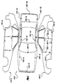
- FIG. 1 With reference to Figure 1, there is shown a typical automotive vehicle body portion which, prior to its assembly with other of the vehicle components, would require gauging of certain key points.
- Such miscellaneous points of interest on workpiece 100 of Figure 1 are shown as points 110-1 through 110-n .
- the left side 100L of the vehicle body and the right side 100R of the vehicle body are shown in an "unfolded" view for convenience in Figure 1.
- Typical usage of the points or the manner in which they are selected would be dictated, for example, by the ensuing assembly process to take place with respect to the workpiece 100 . For example, assume that the hood has not yet been assembled over the hood cavity at the front of the vehicle.
- measurements about the periphery of the hood cavity such as at points 110-6 , 110-7 , 110-8 and 110-9 could be made to determine whether the ensuing assembly of the hood lid to the vehicle body can be performed with an acceptable fit between the parts to be assembled.
- a typical gauging station for an automotive vehicle part as shown in Figure 1 could take the form shown in Figure 2.
- Workpieces to be gauged at gauging station 200 rest on transporting pallets 220 , which are moved along an assembly line via pallet guides 230 that pass through guide channels 231 in the pallet.
- a sensor mounting frame 210 (only one half of which is shown in perspective in Figure 2) surrounds the workpiece 100 to be gauged and provides a plurality of mounting positions for a series of optical gauging sensors or non-contact feature sensors 240-1 through 240-n , each designed in accordance with the disclosure of U.S. Patent No. 4,645,348, for example.
- Communication cables which are not specifically shown in Figure 2 for clarity, couple the sensors 240 to a machine vision computer 250 which includes a CRT or cathode ray tube display 251 .
- a printer 260 Optionally provided with a typical machine vision computer is a printer 260 .
- the apparatus and method of this invention may be used to effect calibration of each of the non-contact sensors 240 with respect to a predetermined external coordinate system or reference frame, associated, for example, with the workpiece 100 to be measured or with respect to an external reference frame associated with the gauging station itself.
- gauging station 200 is shown in conjunction with the calibration system of the present invention.
- the feature sensor 240 includes, but is not limited to, a structured light triangulation sensor.
- the feature sensor 240 is adjustably secured to the gauging station frame at 270 , thereby allowing the feature sensor 240 to be positionally adjusted and then tightened or locked into place once it is properly aimed at the point in space (x, y, z) where the workpiece feature of interest will be located and is properly oriented at the correct attitude (pitch, yaw and roll).
- the non-contact feature sensor 240 includes a sensing zone and an associated sensor reference frame and coordinate system.
- the calibration system of the present invention also includes a portable reference target 400 .
- the portable reference target 400 can be mounted on any suitable fixture, allowing it to be positioned in front of the feature sensor 240 for the calibration operation.
- the portable reference target 400 is shown attached to a simple tripod stand 402 with cantilevered arm 404 . It is envisioned that other support structures may be used within the scope of the present invention.
- the portable reference target 400 is further defined as a three-dimensional framework that provides at least three non-coplanar reflective members 406 that may be illuminated by the structured light emanating from the feature sensor 240 . Although the non-coplanar reflective members 406 provide the feature sensor 240 with spatial data for measuring the position and orientation of the portable reference target 400 , the accuracy of the measurement data is improved by adapting the portable reference target 400 to support light sensitive imaging array devices or passive reflective dots.
- one type of portable reference target 400 is comprised of at least three upright corner members 406 coupled to a planar base 408 .
- An outer corner edge 405 of each member 406 serves as a reflective surface for the structured light plane from the feature sensor 240 .
- a light-sensitive charge coupled device (CCD) or other light sensitive imaging array device is aligned along the outer corner edge 405 of each member 406 .
- the CCDs provide location data as to where the structured light from the non-contact sensor 240 strikes each of the corner members 406 on the portable reference target 400 .
- the CCD is a 1 x N (linear) device, where N is selected to provide suitable resolution (e.g., 4096 pixels).
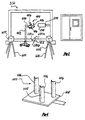
- the calibration system further includes a target calibration device 600 which may be positioned at a convenient vantage point, such as above the space that is occupied by the workpiece in the gauging station 200 .
- the target calibration device 600 can be temporarily positioned in a fixed location, such as by hanging it from the gauging station frame or mounting it on a movable stand, allowing the target calibration device 600 to be moved from location to location throughout the manufacturing facility.
- a photogrammetry system serves as the target calibration device 600 .
- Photogrammetry systems work on well known principles of using dots or points of light as photogrammetry targets.
- at least two cameras 604 , 605 that are calibrated as a pair can be used to measure the photogrammetry targets in a three-dimensional coordinate frame.
- the photogrammetry system can measure the XYZ coordinates of at least three non-collinear points with known coordinates affixed to the portable reference target 400 , thus creating a full six-degree-of-freedom link between the feature sensor 240 and the photogrammetry system, It should be noted that some commercially available photogrammetry systems can provide fast enough response times to provide real-time position feedback of the sensor.
- An exemplary photogrammetric camera is the ProReflex Motion Capture System manufactured by Qualisys AB of Savedalen, Sweden or the Metronor System manufactured by Metronor ASA of Nesbru, Norway.
- the two photogrammetric cameras 604 , 605 are positioned at a convenient vantage point, such as above and/or adjacent to the space that is occupied by the workpiece in the gauging station 200 .
- a plurality of non-colinear photogrammetry targets are also incorporated into the base of the portable reference target 400 .
- light-emitting diodes serve as the photogrammetry targets.
- simple switched LED devices are easy to implement and therefore presently preferred, other types of active or passive (e.g., dots, holes or retro-reflectors) photogrammetry targets may be used in the present invention.
- a series of dots aligned on the upright members of the portable reference target may also serve as the photogrammetry targets.
- the photogrammetric cameras will provide an accurate determination of the position of the portable reference target 400 . More specifically, three or more non-collinear photogrammetry target measurements will yield a six degree-of-freedom location and orientation of the portable reference target 400 .
- a second alternative preferred embodiment for the portable reference target 401 uses a series of dots 414 in place of each light sensitive imaging array device.
- the portable reference target 403 is generally a three-dimensional framework that provides at least three non-coplanar reflective surfaces.
- the framework is comprised of at least three upright members 410 which are coupled to a planar base 412 .
- the series of visible dots 414 are aligned vertically along the surface of each upright member 410 . It is envisioned that the visible dots 414 may be active (e.g., light emitting diodes) or passive (dots, holes or retro-reflectors).
- a third alternative preferred embodiment of the portable reference target 403 is shown in Figure 6.
- the portable reference target body 403 utilizes a series of visible dots 414 in place of each light sensitive imaging array device.
- the portable reference target 403 is also a three-dimensional framework that provides at least three non-coplanar reflective surfaces.
- the framework is comprised of at least three upright surfaces 410 formed on a solid T-shaped body 411 .
- the body 411 is then secured to a planar base 412 .
- a series of visible dots 414 are aligned vertically along each upright surface 410 .
- the visible dots 414 are preferably passive black dots against a white background.
- the visible dots 414 may also be other types of passive shapes including holes or retroreflectors, or may be active devices such as light emitting diodes.
- a retroreflector 802 may be mounted to the top surface of the T-shaped body.
- the retroreflector 802 may also be mounted to other locations of the portable reference target 401 .
- the portable reference targets 401, 403 are illuminated by the structured light emanating from the non-contact feature sensor 240 .
- an auxiliary light may be used to illuminate the visible dots 414 or holes above and below the laser line.
- the calibration system which operates the feature sensor 240 is able to calibrate the feature sensor 240 based on the spatial location of the visible dots 414 on the portable reference target 401, 403 .
- the emanating structured light from the sensor may strike the area between two dots 414 on an upright member 410 .
- One type of non-contact feature sensor 240 is designed to only perform measurements within the structured light plane, so in this case a correction is needed.
- the target calibration device 600 is calibrated to the external reference frame so that the exact location of the it is known within the external reference frame. This location is then stored in a memory.
- a coordinate transformation system connected to the target calibration device can be used for this step.
- the coordinate transformation system is a processor forming part of the machine vision computer 250 of Figure 2.
- the portable reference target 400 is placed within the calibration field of the target calibration device.
- the target calibration device 600 then establishes a relationship between the portable reference target 401 and the reference frame of the target calibration device 600 .
- the feature sensor 240 projects structured light onto the portable reference target 400 and collects reflected light data from the portable reference target 400 .
- the position of the upright surfaces are ascertained and then used to describe the spatial position of the portable reference target 400 in the reference frame of the non-contact feature sensor 240 .
- the calibration system of the present invention simultaneously collects data from the non-contact feature sensor 240 and the target calibration device 600 .
- the calibration system also collects data from the imaging array devices on the reference target.
- measurement data is combined in order to locate and calibrate the non-contact sensor 240 with respect to the external reference frame.
- the feature sensor 240 is then partially calibrated with respect to the fixed reference frame R E . It will be necessary to repeat this measurement at preferably four different locations within the sensor field of view to determine complete position and orientation of the non-contact feature sensor 240 with respect to the external reference frame and coordinate system.
- the above steps for determining complete position and orientation of the non-contact feature sensor 240 can be performed by the processor executing the coordinate transformation system.
- the target calibration device 600 was calibrated first, the position of the portable reference target 401 was calibrated second, and the non-contact feature sensor 240 was calibrated third, It is envisioned that these operations could be performed in a different sequence and thereby achieve the same end result.
- a servo driven laser tracker serves as the target calibration device.
- a servo driven laser tracker 800 may be positioned at a convenient vantage point in the gauging station, such as above the space that is occupied by the workpiece.
- the laser tracker can be temporarily positioned at a location within the gauging station, such as by hanging it from the gauging station frame or mounting it on a movable stand.
- the servo driven laser tracker 800 emits an outgoing laser beam and detects an incoming laser beam.
- the laser tracker 800 includes a servo drive mechanism with closed loop controller that points the laser tracker in the direction of the incoming beam as reflected by a retroreflector 802 .
- the laser tracker 800 will precisely follow or track the position of the retroreflector 802 .
- the retroreflector is preferably affixed to the top surface of the reference target 403 .
- the laser tracker system can precisely track where the center of the retroreflector is at all times, even as the retroreflector is moved around within the gauging station.
- the servo system and closed loop controller of the laser tracker provides a signal indicative of the line of sight through the center of the retroreflector and suitable interferometer measurements can be used to accurately ascertain the distance between the center of the retroreflector and the laser tracker.
- the laser tracker provides only a partial link to the external reference frame. It will generate the X, Y, Z position of the retroreflector.
- the reference target may be moved to three or more locations while acquiring data. Preferably, four or more non-collinear location points are used. Once this has been done the data may be used to triangulate onto a six degree-of-freedom location and orientation for the reference target.
- a theodolite system 900 serves as the target calibration device.
- a theodolite system 900 is a commercially available survey instrument system for measuring horizontal and vertical angles, similar in principle to the transit. The fundamental mathematical principle of operation of the theodolites is based on triangulation, such that theodolites are able to measure both horizontal and vertical angles to a selected target.
- An exemplary theodolite system for use with this invention may include a T105 Theodolite heads from Leica supported by a PC running Axyz software.
- At least two theodolite devices 902 and 904 are positioned at a convenient vantage points in the space that is occupied by the workpiece in the gauging station 200 .
- a plurality of non-colinear theodolite observable targets are incorporated into the base of the portable reference target 401 .
- These theodolite observable targets may include scribe marks, stick-on dots, machined holes or other well known types of theodolite observable targets.
- an accurate determination of the position of the reference target 401 is provided by theodolite system 900 .
- the calibration system of the present invention otherwise operates in accordance with the previously described embodiments for either of these alternative target calibration devices.
- the above target calibration devices are presently preferred, this is not intended as a limitation on the broader aspects of the invention.
- a commercially available portable measurement arm may also be used as the target calibration device.
- the reference target is coupled to an end effector of the arm. Since the arm is a six degree-of-freedom measuring tool, the calibration system can deduce the actual position of the sensor as its positioned by the measurement arm.
- An exemplary measurement arm is manufactured by Romer of Carlsbad, California.
Abstract
Description
- The present invention relates generally to non-contact gauging systems. More particularly, the invention relates to an apparatus system and method for calibrating non-contact gauging systems.
- Demand for higher quality has pressed manufacturers of mass produced articles, such as automotive vehicles, to employ automated manufacturing techniques that were unheard of when assembly line manufacturing was first conceived. Today, robotic equipment is used to assemble, weld, finish, gauge and test manufactured articles with a much higher degree of quality and precision than has been heretofore possible. Computer-aided manufacturing techniques allow designers to graphically conceptualize and design a new product on a computer workstation and the automated manufacturing process ensures that the design is faithfully carried out precisely according to specification. Machine vision is a key part of today's manufacturing environment. Machine vision systems are used with robotics and computer-aided design systems to ensure high quality is achieved at the lowest practical cost.
- Achieving high quality manufactured parts requires highly accurate, tightly calibrated machine vision sensors. Not only must a sensor have a suitable resolution to discern a manufactured feature of interest, the sensor must be accurately calibrated to a known frame of reference so that the feature of interest may be related to other features on the workpiece. Without accurate calibration, even the most sensitive, high resolution sensor will fail to produce high quality results.
- In a typical manufacturing environment, there may be a plurality of different non-contact sensors, such as optical sensors, positioned at various predetermined locations within the workpiece manufacturing, gauging or testing station. The workpiece is placed at a predetermined, fixed location within the station, allowing various predetermined features of the workpiece to be examined by the sensors. Preferably, all of the sensors are properly positioned and should be carefully calibrated with respect to some common fixed frame of reference, such as a common reference frame on the workpiece or at the workstation.
- Maintaining sensors which are properly positioned and calibrated presents several challenges. In a typical manufacturing environment sensors and their associated mounting structures may get bumped or jarred, throwing the sensor out of alignment. Also, from time to time, a sensor needs to be replaced, almost certainly requiring reorienting and recalibrating. Quite simply, sensor positioning, alignment and calibration requires careful attention in the typical manufacturing plant.
- Proper sensor positioning, alignment and calibration can present significant time and labor requirements. For a given part or assembly, the entire manufacturing assembly line may need to be shut down and the workstation cleared, so that the sensor may be positioned, aligned and recalibrated. In some instances this entails placing a highly accurate, and very expensive full-scale model of the part or assembly into the workstation. This independently measured part is sometimes called a master part. The master part is placed in careful registration with the external coordinate system of the workstation and then each sensor is trained on its assigned feature (such as a hole or edge). Once positioned, the sensors are locked into place and calibrated and the master part is removed. Only then can the assembly line be brought back online.
- As an alternative to using a master part, it is possible to calibrate the gauging sensor by attaching a target to the sensor and illuminating the target using a plane of structured light produced by the sensor. A pair of optical sighting devices, such as theodolites, are placed at different vantage points within the workspace. The theodolites triangulate on the illuminated target to provide an independent reading of the position of the target. The theodolites are placed at carefullly prescribed locations relative to an external reference frame. With the gauging sensor projecting structured light onto the target, the theodolites are manually aimed at the illuminated targets and readings are taken. The respective readings of the theodolites and the gauging sensor are coordinated and translated to calibrate the sensor relative to the external reference frame. It is a trial and error process. If the sensor needs to be reoriented (as is often the case), the theodolites must be manually retrained on the target after each sensor position adjustment. For more information on this calibration technique, see U.S. Patent No. 4,841,460 to Dewar et al.
- Whereas both of the aforementioned calibration techniques do work, there is considerable interest in a calibration technique that is more efficient and easier to accomplish, and which eliminates the need to rely on expensive master parts. To this end, the present invention provides a calibration system that can be used in a matter of minutes, instead of hours, and without the need for precisely manufactured master parts. One of the major advantages of the invention is that it allows the calibration of the sensors to be checked or realigned between line shifts, without requiring the line to be shut down for an extended period.
- The calibration system employs reference indicia that are disposed in fixed relation to the external reference frame of the manufacturing or assembly zone or gauging station. A target calibration device is positioned at a vantage point, typically above the gauging station, so that the reference indicia are within the field of view of the target calibration device. The target calibration device is operative to determine the spatial location and orientation of a portable reference target within the gauging station. Exemplary target calibration devices may include, but are not limited to a photogrammetry system, a theodolite system, or a laser tracker system.
- The calibration system further employs a portable reference target that is placed within the observation field of the target calibration device and also within the sensing zone of the feature sensor. The presently preferred portable reference target is a three-dimensional framework that provides at least three non-coplanar reflective structures (e.g., straight edges) that can be illuminated by structured light emanating from the feature sensor. As part of the present invention the feature sensor includes, but is not limited to, a structured light triangulation sensor. Although the non-coplanar reflective structures provide the feature sensor with spatial data for measuring the position and orientation of the portable reference target, the present invention improves the accuracy of the measurement data by adapting the target to support a visible dot pattern or a light sensitive imaging array device (e.g., CCD). In this way, the portable reference target provides unambiguous spatial data for measuring its spatial position and orientation.
- The calibration system further includes a coordinate transformation system for coordinating the measurement data from the target calibration device and from the feature sensor. More specifically, the calibration system is adapted to collect data from the target calibration device and the feature sensor. The transformation system establishes a first relationship between the reference frame of the target calibration device and the external reference frame. The transformation system also establishes a second relationship between the reference frame of the target calibration device and the reference frame of the feature sensor. Finally, the transformation system determines a third relationship between the reference frame of the feature sensor and the external reference frame, whereby the feature sensor is calibrated with respect to the external reference frame.
- The system and technique of the present invention allows for simplified calibration of a feature sensor. The target calibration device is first calibrated via the reference indicia to the external reference frame. Next, the portable reference target is placed within the field of view of the target calibration device and the feature sensor. The portable reference target is calibrated with respect to the reference frame of the target calibration device. The feature sensor is then calibrated by projecting structured light from the feature sensor onto the portable reference target. The structured light intersects the target, producing reflected light patterns at the edges of the target that are then read by the feature sensor. The coordinate transformation system simultaneously receives measurement data as to where the structured light strikes the dot patterns or the light sensitive imaging array devices associated with the target. The coordinate transformation system then performs the appropriate coordinate transformation to map the data of the feature sensor back to the external reference frame. The entire calibration sequence can be performed quite quickly.
- For a more complete understanding of the invention, its objects and advantages, reference may be had to the following specification and to the accompanying drawings.
-
- Figure 1 is a simultaneous top and side view of a portion of an automotive vehicle body, showing typical points of interest which would be placed in the field of view of a plurality of non-contact feature sensors at a gauging station;
- Figure 2 is a perspective view of a typical gauging station on an automotive assembly line, including a plurality of non-contact feature sensors to be calibrated in accordance with the principles of the invention;
- Figure 3 is a side elevational view of a calibration system in accordance with the teachings of the present invention;
- Figure 4 is perspective view of a portable reference target body in accordance with one embodiment of the present invention which employs imaging array CCD devices;
- Figure 5 is a perspective view of a second alternative embodiment of the portable reference target body in accordance with the present invention;
- Figure 6 is a perspective view of a third alternative embodiment of the portable reference target in accordance with the present invention;
- Figure 7 is a diagram showing the how the location of the visible dot on the reference target may be determined by the feature sensor in accordance with the present invention;
- Figure 8 is a flowchart further illustrating the calibration method of the present invention;
- Figure 9 is a perspective view of a preferred embodiment of the present invention which employs a laser tracker system as the target calibration device; and
- Figure 10 is a perspective view of an alternative preferred embodiment of the present invention which employs a theodolite system as the target calibration device.
-
- With reference to Figure 1, there is shown a typical automotive vehicle body portion which, prior to its assembly with other of the vehicle components, would require gauging of certain key points. Such miscellaneous points of interest on
workpiece 100 of Figure 1 are shown as points 110-1 through 110-n. The left side 100L of the vehicle body and the right side 100R of the vehicle body are shown in an "unfolded" view for convenience in Figure 1. Typical usage of the points or the manner in which they are selected would be dictated, for example, by the ensuing assembly process to take place with respect to theworkpiece 100. For example, assume that the hood has not yet been assembled over the hood cavity at the front of the vehicle. Then measurements about the periphery of the hood cavity, such as at points 110-6, 110-7, 110-8 and 110-9 could be made to determine whether the ensuing assembly of the hood lid to the vehicle body can be performed with an acceptable fit between the parts to be assembled. - While there are many sensor arrangements known, including the optical arrangement disclosed in U.S. Patent 4,645,348 to Dewar et al., assigned to the assignee of the present invention, it has been time consuming to calibrate the sensor readings at all the desired points of interest about a large workpiece with respect to any desired external reference frame. The present invention addresses the need for faster calibration.
- A typical gauging station for an automotive vehicle part as shown in Figure 1 could take the form shown in Figure 2. Workpieces to be gauged at gauging
station 200 rest on transportingpallets 220, which are moved along an assembly line via pallet guides 230 that pass throughguide channels 231 in the pallet. At the gaugingstation 200, a sensor mounting frame 210 (only one half of which is shown in perspective in Figure 2) surrounds theworkpiece 100 to be gauged and provides a plurality of mounting positions for a series of optical gauging sensors or non-contact feature sensors 240-1 through 240-n, each designed in accordance with the disclosure of U.S. Patent No. 4,645,348, for example. Communication cables which are not specifically shown in Figure 2 for clarity, couple thesensors 240 to amachine vision computer 250 which includes a CRT or cathoderay tube display 251. Optionally provided with a typical machine vision computer is aprinter 260. The apparatus and method of this invention may be used to effect calibration of each of thenon-contact sensors 240 with respect to a predetermined external coordinate system or reference frame, associated, for example, with theworkpiece 100 to be measured or with respect to an external reference frame associated with the gauging station itself. - Referring to Figure 3, gauging
station 200 is shown in conjunction with the calibration system of the present invention. To simplify the illustration, only onefeature sensor 240 has been illustrated. As part of the present invention thefeature sensor 240 includes, but is not limited to, a structured light triangulation sensor. Thefeature sensor 240 is adjustably secured to the gauging station frame at 270, thereby allowing thefeature sensor 240 to be positionally adjusted and then tightened or locked into place once it is properly aimed at the point in space (x, y, z) where the workpiece feature of interest will be located and is properly oriented at the correct attitude (pitch, yaw and roll). Thenon-contact feature sensor 240 includes a sensing zone and an associated sensor reference frame and coordinate system. - The calibration system of the present invention also includes a
portable reference target 400. Theportable reference target 400 can be mounted on any suitable fixture, allowing it to be positioned in front of thefeature sensor 240 for the calibration operation. In this case, theportable reference target 400 is shown attached to asimple tripod stand 402 with cantilevered arm 404. It is envisioned that other support structures may be used within the scope of the present invention. Theportable reference target 400 is further defined as a three-dimensional framework that provides at least three non-coplanarreflective members 406 that may be illuminated by the structured light emanating from thefeature sensor 240. Although the non-coplanarreflective members 406 provide thefeature sensor 240 with spatial data for measuring the position and orientation of theportable reference target 400, the accuracy of the measurement data is improved by adapting theportable reference target 400 to support light sensitive imaging array devices or passive reflective dots. - Referring to Figure 4, one type of
portable reference target 400 is comprised of at least threeupright corner members 406 coupled to aplanar base 408. Anouter corner edge 405 of eachmember 406 serves as a reflective surface for the structured light plane from thefeature sensor 240. A light-sensitive charge coupled device (CCD) or other light sensitive imaging array device is aligned along theouter corner edge 405 of eachmember 406. In this way, the CCDs provide location data as to where the structured light from thenon-contact sensor 240 strikes each of thecorner members 406 on theportable reference target 400. It is envisioned that the CCD is a 1 x N (linear) device, where N is selected to provide suitable resolution (e.g., 4096 pixels). One skilled in the art will readily recognize from such discussions that other geometric configurations providing at least three non-coplanar reflective surfaces may be used for the portable reference target - Referring back to Figure 3, the calibration system further includes a
target calibration device 600 which may be positioned at a convenient vantage point, such as above the space that is occupied by the workpiece in the gaugingstation 200. Alternatively, thetarget calibration device 600 can be temporarily positioned in a fixed location, such as by hanging it from the gauging station frame or mounting it on a movable stand, allowing thetarget calibration device 600 to be moved from location to location throughout the manufacturing facility. - According to one aspect of the present invention, a photogrammetry system serves as the
target calibration device 600. Photogrammetry systems work on well known principles of using dots or points of light as photogrammetry targets. In general, at least twocameras portable reference target 400, thus creating a full six-degree-of-freedom link between thefeature sensor 240 and the photogrammetry system, It should be noted that some commercially available photogrammetry systems can provide fast enough response times to provide real-time position feedback of the sensor. An exemplary photogrammetric camera is the ProReflex Motion Capture System manufactured by Qualisys AB of Savedalen, Sweden or the Metronor System manufactured by Metronor ASA of Nesbru, Norway. - The two
photogrammetric cameras station 200. A plurality of non-colinear photogrammetry targets (not specifically shown) are also incorporated into the base of theportable reference target 400. In the presently preferred embodiment, light-emitting diodes (LEDs) serve as the photogrammetry targets. Although simple switched LED devices are easy to implement and therefore presently preferred, other types of active or passive (e.g., dots, holes or retro-reflectors) photogrammetry targets may be used in the present invention. It is further envisioned that a series of dots aligned on the upright members of the portable reference target (as described below) may also serve as the photogrammetry targets. As long as theportable reference target 400 is within the field of view of thephotogrammetric cameras portable reference target 400. More specifically, three or more non-collinear photogrammetry target measurements will yield a six degree-of-freedom location and orientation of theportable reference target 400. - To illustrate the principals of the invention, it will be assumed that the
feature sensor 240 is to be calibrated with respect to an external frame of reference associated with the stationary gaugingstation 200. In this regard, external reference frame RE has been diagrammatically included in Figure 3. A plurality ofnon-colinear reference indicia station 200. - With reference to Figure 6, a second alternative preferred embodiment for the
portable reference target 401 uses a series ofdots 414 in place of each light sensitive imaging array device. Theportable reference target 403 is generally a three-dimensional framework that provides at least three non-coplanar reflective surfaces. In particular, the framework is comprised of at least threeupright members 410 which are coupled to aplanar base 412. The series ofvisible dots 414 are aligned vertically along the surface of eachupright member 410. It is envisioned that thevisible dots 414 may be active (e.g., light emitting diodes) or passive (dots, holes or retro-reflectors). - A third alternative preferred embodiment of the
portable reference target 403 is shown in Figure 6. Again, the portablereference target body 403 utilizes a series ofvisible dots 414 in place of each light sensitive imaging array device. Theportable reference target 403 is also a three-dimensional framework that provides at least three non-coplanar reflective surfaces. In this case, the framework is comprised of at least threeupright surfaces 410 formed on a solid T-shapedbody 411. Thebody 411 is then secured to aplanar base 412. A series ofvisible dots 414 are aligned vertically along eachupright surface 410. Thevisible dots 414 are preferably passive black dots against a white background. However, thevisible dots 414 may also be other types of passive shapes including holes or retroreflectors, or may be active devices such as light emitting diodes. To the extent that the target calibration device is a laser tracker, aretroreflector 802 may be mounted to the top surface of the T-shaped body. However, theretroreflector 802 may also be mounted to other locations of theportable reference target 401. - In operation, the
portable reference targets non-contact feature sensor 240. In the case of passive visible dots or holes, an auxiliary light may be used to illuminate thevisible dots 414 or holes above and below the laser line. The calibration system which operates thefeature sensor 240 is able to calibrate thefeature sensor 240 based on the spatial location of thevisible dots 414 on theportable reference target dots 414 on anupright member 410. One type ofnon-contact feature sensor 240 is designed to only perform measurements within the structured light plane, so in this case a correction is needed. Even though adot 414 does not lie in the measurement plane of thesensor 240, it appears in the plane as shown in Figure 7. In this case, a simple geometric projection is performed in three dimensional space to determine the physical location of thevisible dot 414, and therefore determine the location of theportable reference target feature sensor 240. - Referring to Figure 8, the calibration technique of the present invention will now be described. First, the
target calibration device 600 is calibrated to the external reference frame so that the exact location of the it is known within the external reference frame. This location is then stored in a memory. A coordinate transformation system connected to the target calibration device can be used for this step. Preferably, the coordinate transformation system is a processor forming part of themachine vision computer 250 of Figure 2. Atstep 701, theportable reference target 400 is placed within the calibration field of the target calibration device. Thetarget calibration device 600 then establishes a relationship between theportable reference target 401 and the reference frame of thetarget calibration device 600. - Next, at
step 702, thefeature sensor 240 projects structured light onto theportable reference target 400 and collects reflected light data from theportable reference target 400. As previously described, the position of the upright surfaces are ascertained and then used to describe the spatial position of theportable reference target 400 in the reference frame of thenon-contact feature sensor 240. In order to determine the orientation of theportable reference target 400, the calibration system of the present invention simultaneously collects data from thenon-contact feature sensor 240 and thetarget calibration device 600. In the case of the first embodiment of the reference target, the calibration system also collects data from the imaging array devices on the reference target. Atstep 703, measurement data is combined in order to locate and calibrate thenon-contact sensor 240 with respect to the external reference frame. Once this data is collected, thefeature sensor 240 is then partially calibrated with respect to the fixed reference frame RE. It will be necessary to repeat this measurement at preferably four different locations within the sensor field of view to determine complete position and orientation of thenon-contact feature sensor 240 with respect to the external reference frame and coordinate system. The above steps for determining complete position and orientation of thenon-contact feature sensor 240 can be performed by the processor executing the coordinate transformation system. - In the foregoing example, the
target calibration device 600 was calibrated first, the position of theportable reference target 401 was calibrated second, and thenon-contact feature sensor 240 was calibrated third, It is envisioned that these operations could be performed in a different sequence and thereby achieve the same end result. - In addition to the photogrammetry system, other target calibration devices may be used in conjunction with the calibration system of the present invention. In an alternative embodiment, a servo driven laser tracker serves as the target calibration device. Referring to Figure 9, a servo driven
laser tracker 800 may be positioned at a convenient vantage point in the gauging station, such as above the space that is occupied by the workpiece. Alternatively, the laser tracker can be temporarily positioned at a location within the gauging station, such as by hanging it from the gauging station frame or mounting it on a movable stand. - The servo driven
laser tracker 800 emits an outgoing laser beam and detects an incoming laser beam. Thelaser tracker 800 includes a servo drive mechanism with closed loop controller that points the laser tracker in the direction of the incoming beam as reflected by aretroreflector 802. As long as the laser tracker is within the 45-60° field of view of the retroreflector, thelaser tracker 800 will precisely follow or track the position of theretroreflector 802. In the present invention, the retroreflector is preferably affixed to the top surface of thereference target 403. Thus, the laser tracker system can precisely track where the center of the retroreflector is at all times, even as the retroreflector is moved around within the gauging station. - In operation, the servo system and closed loop controller of the laser tracker provides a signal indicative of the line of sight through the center of the retroreflector and suitable interferometer measurements can be used to accurately ascertain the distance between the center of the retroreflector and the laser tracker. However, the laser tracker provides only a partial link to the external reference frame. It will generate the X, Y, Z position of the retroreflector. In order to acquire all six degrees-of-freedom (X, Y, Z as well as roll, pitch, yaw) the reference target may be moved to three or more locations while acquiring data. Preferably, four or more non-collinear location points are used. Once this has been done the data may be used to triangulate onto a six degree-of-freedom location and orientation for the reference target.
- In another preferred embodiment, a
theodolite system 900 serves as the target calibration device. Atheodolite system 900 is a commercially available survey instrument system for measuring horizontal and vertical angles, similar in principle to the transit. The fundamental mathematical principle of operation of the theodolites is based on triangulation, such that theodolites are able to measure both horizontal and vertical angles to a selected target. An exemplary theodolite system for use with this invention may include a T105 Theodolite heads from Leica supported by a PC running Axyz software. - As shown in Figure 10, at least two
theodolite devices station 200. While not specifically shown, a plurality of non-colinear theodolite observable targets are incorporated into the base of theportable reference target 401. These theodolite observable targets may include scribe marks, stick-on dots, machined holes or other well known types of theodolite observable targets. Again, as long as thereference target 401 is within the field of view of thetheodolite devices reference target 401 is provided by thetheodolite system 900. Using twotheodolite devices portable reference target 401. The calibration system of the present invention otherwise operates in accordance with the previously described embodiments for either of these alternative target calibration devices. - Although the above target calibration devices are presently preferred, this is not intended as a limitation on the broader aspects of the invention. On the contrary, it is envisioned that a commercially available portable measurement arm may also be used as the target calibration device. In this case, the reference target is coupled to an end effector of the arm. Since the arm is a six degree-of-freedom measuring tool, the calibration system can deduce the actual position of the sensor as its positioned by the measurement arm. An exemplary measurement arm is manufactured by Romer of Carlsbad, California.
- While the invention has been described in its presently preferred form, it will be understood that the invention is capable of modification without departing from the spirit of the invention as set forth in the appended claims.
Claims (14)
- A sensor calibration system for calibrating a non-contact sensor (240) with respect to an external reference frame (RE), in particular for a motor vehicle manufacturing system, the non-contact sensor (240) of the type having a sensing zone associated with a sensor reference frame, characterized by:a target calibration device (600) having a calibration field of observation associated with a calibration device reference frame; anda reference target (400, 401, 403) for placement within the observation field of said target calibration device (600) and within the sensing zone of said non-contact sensor (240), said reference target (400, 401, 403) having at least three non-coplanar reflective surfaces (406).
- The calibration system of Claim 1, characterized in that each reflective surface (406) of the reference target (400, 401, 403) is adapted to support an imaging array.
- The calibration system of Claim 1 or 2, characterized in that the non-contact sensor (240) is an active optical feature sensor (240) that emits structured light and each imaging array is operable to detect the structured light from the feature sensor (240), thereby determining the location of the reference target (400, 401, 403) in relation to the feature sensor (240).
- The calibration system of any of Claims 1 to 3, characterized in that each reflective surface member (406) has a series of visible dots (414) aligned along the reflective surface.
- The calibration system of Claim 4, characterized in that the feature sensor (240) is an active optical sensor that emits structured light and detects reflected light, such that the feature sensor (240) is operable to determine the location of at least one of the visible dots (414) on each reflective surface (406) and thereby determine the location of the reference target (400, 401, 403) in relation to the feature sensor (240).
- The calibration system of Claim 1, characterized by:a reference indicia (280a, b, c) disposed in fixed relation to said external reference frame (RE), such that the target calibration device (600) is positionable at vantage points where the reference indicia (280a, b, c) is within the calibration field; anda coordinate transformation system being adapted for coupling to said target calibration device (600) for collecting data from said reference indicia (280a, b, c) and for establishing a first relationship between the calibration device reference frame and external reference frame (RE);said coordinate transformation system further being adapted for coupling to said target calibration device (600) and to said feature sensor (240) for collecting data from the reference target (400, 401, 403) and for establishing a second relationship between the calibration device reference frame and the feature sensor reference frame; andsaid coordinate transformation system determining a third relationship between the external reference frame (RE) and the feature sensor reference frame, whereby the feature sensor (240) is calibrated with respect to the external reference frame (RE).
- The calibration system of any of Claims 1 to 6, characterized in that said target calibration device (600) is further defined by a laser tracker (800).
- The calibration system of any of Claims 1 to 7, characterized in that said reference target further includes a retroreflector (802) affixed to the reference target.
- The calibration system of any of Claims 1 to 8, characterized in that said laser tracker (800) tracks a center position of said retroreflector (802) in at least three non-colinear locations, thereby establishing said second relationship between the calibration device reference frame and the feature sensor reference frame.
- The calibration system of any of Claims 6 to 9, characterized in that said target calibration device (600) is further defined by at least two photogrammetric cameras (604, 605) being positionabls at two or more vantage points such that said reference indicia (280a, b, c) is within the calibration field.
- The calibration system of any of Claims 1 to 10, characterized in that said reference target (400, 401, 403) further includes a plurality of photogrammetry targets or theodolite targets.
- The calibration system of Claim 10 or 11, characterized in that said photogrammetric cameras (604, 605) measure a position of said reference target (400, 401, 403) in at least two non-collinear locations, thereby establishing said second relationship between the calibration device reference frame and the feature sensor reference frame.
- The calibration system of Claim 11 or 12, characterized in that said theodolite targets measure a position of said reference target in at least three locations, thereby establishing said second relationship between the calibration device reference frame and the feature sensor reference frame.
- The calibration system of any of Claims 1 to 13, characterized by a gauging station (200) for gauging a workpiece, in particular a motor vehicle, said feature sensor (240) being securely connected to said gauging station (200) for determining positions upon said workpiece (100).
Applications Claiming Priority (4)
| Application Number | Priority Date | Filing Date | Title |
|---|---|---|---|
| US15776999P | 1999-10-05 | 1999-10-05 | |
| US157769P | 1999-10-05 | ||
| US18579600P | 2000-02-29 | 2000-02-29 | |
| US185796P | 2000-02-29 |
Publications (2)
| Publication Number | Publication Date |
|---|---|
| EP1091186A2 true EP1091186A2 (en) | 2001-04-11 |
| EP1091186A3 EP1091186A3 (en) | 2001-12-12 |
Family
ID=26854475
Family Applications (1)
| Application Number | Title | Priority Date | Filing Date |
|---|---|---|---|
| EP00121738A Withdrawn EP1091186A3 (en) | 1999-10-05 | 2000-10-05 | Method and apparatus for calibrating a non-contact gauging sensor with respect to an external coordinate system |
Country Status (3)
| Country | Link |
|---|---|
| EP (1) | EP1091186A3 (en) |
| JP (1) | JP2001264062A (en) |
| CA (1) | CA2322367A1 (en) |
Cited By (21)
| Publication number | Priority date | Publication date | Assignee | Title |
|---|---|---|---|---|
| WO2002086420A1 (en) * | 2001-04-19 | 2002-10-31 | Dimensional Photonics, Inc. | Calibration apparatus, system and method |
| WO2002088630A1 (en) * | 2001-04-24 | 2002-11-07 | Krypton Electronic Engineering N.V. | Method and device for the verification and identification of a measuring device |
| WO2002097362A1 (en) * | 2001-05-31 | 2002-12-05 | Bae Systems Plc | Photogrammetry targets |
| WO2003044458A1 (en) * | 2001-11-23 | 2003-05-30 | Mapvision Oy Ltd | Method and system for the calibration of a computer vision system |
| WO2005017450A1 (en) * | 2003-08-11 | 2005-02-24 | Multi-Dimension Technology, Llc | Calibration block and calibration system for 3d scanner |
| US7084386B2 (en) * | 2003-05-02 | 2006-08-01 | International Business Machines Corporation | System and method for light source calibration |
| DE102006026265A1 (en) * | 2006-06-02 | 2007-12-06 | Benteler Automobiltechnik Gmbh | Device for optical measurement and / or inspection of welded assemblies |
| WO2012019877A1 (en) * | 2010-08-12 | 2012-02-16 | Robert Bosch Gmbh | Method for calibrating a measurement system and device for carrying out the method |
| CN103115612A (en) * | 2013-01-25 | 2013-05-22 | 爱佩仪中测(成都)精密仪器有限公司 | Digital photogrammetry system combined with laser tracking technology, and combined measured target |
| WO2013096454A1 (en) * | 2011-12-19 | 2013-06-27 | Perceptron, Inc. | Non-contact sensor having improved laser spot |
| EP2837907A1 (en) * | 2013-08-14 | 2015-02-18 | Telmat Industrie (Société Anonyme) | Method and device for automatic acquisition of three-dimensional surfaces |
| CN104697500A (en) * | 2015-02-05 | 2015-06-10 | 北京林业大学 | Method for determining moving target state parameters based on image method |
| EP3040677A1 (en) * | 2015-01-05 | 2016-07-06 | BAE Systems PLC | Calibration verification tool |
| US10197539B2 (en) | 2015-01-05 | 2019-02-05 | Bae Systems Plc | System and method for assessing a calibration of a multi-axis ultrasonic scanner |
| EP3368858A4 (en) * | 2015-10-30 | 2019-06-26 | Carestream Dental Technology Topco Limited | Target with features for 3-d scanner calibration |
| WO2020000137A1 (en) * | 2018-06-25 | 2020-01-02 | Beijing DIDI Infinity Technology and Development Co., Ltd | Integrated sensor calibration in natural scenes |
| CN111854589A (en) * | 2019-04-29 | 2020-10-30 | 核工业理化工程研究院 | Rapid calibration device and calibration method for contact type displacement sensor array |
| CN112549018A (en) * | 2020-11-03 | 2021-03-26 | 武汉数字化设计与制造创新中心有限公司 | Robot line laser rapid hand-eye calibration method |
| US11092667B2 (en) | 2017-12-20 | 2021-08-17 | Bosch Automotive Service Solutions Inc. | Portable apparatus for vehicle sensor calibration |
| US11162785B2 (en) | 2018-02-26 | 2021-11-02 | Bosch Automotive Service Solutions Inc. | Assisted portable vehicle sensor calibration alignment |
| CN115210134A (en) * | 2020-03-11 | 2022-10-18 | 本田技研工业株式会社 | Target setting device |
Families Citing this family (6)
| Publication number | Priority date | Publication date | Assignee | Title |
|---|---|---|---|---|
| ATE494561T1 (en) * | 2002-11-15 | 2011-01-15 | Leica Geosystems Ag | METHOD AND DEVICE FOR CALIBRATION OF A MEASURING SYSTEM |
| KR101405212B1 (en) | 2012-12-21 | 2014-06-27 | 현대자동차 주식회사 | Calibration Target Apparatus of Radar Sensor |
| JP6179979B2 (en) * | 2013-06-07 | 2017-08-16 | 能美防災株式会社 | Structure deterioration diagnosis system |
| CN106370142B (en) * | 2016-11-15 | 2023-12-15 | 江苏方天电力技术有限公司 | Calibration device and calibration method for wide-range displacement sensor |
| CN114166126A (en) * | 2021-12-08 | 2022-03-11 | 中航西安飞机工业集团股份有限公司 | Calibration device and calibration method for laser scanning equipment |
| CN114322767A (en) * | 2021-12-29 | 2022-04-12 | 北京交通大学 | Space multi-point positioning method, device, equipment and medium based on multi-line fitting |
Citations (5)
| Publication number | Priority date | Publication date | Assignee | Title |
|---|---|---|---|---|
| US4645348A (en) * | 1983-09-01 | 1987-02-24 | Perceptron, Inc. | Sensor-illumination system for use in three-dimensional measurement of objects and assemblies of objects |
| US5446548A (en) * | 1993-10-08 | 1995-08-29 | Siemens Medical Systems, Inc. | Patient positioning and monitoring system |
| US5748505A (en) * | 1996-02-06 | 1998-05-05 | Perceptron, Inc. | Method and apparatus for calibrating a noncontact gauging sensor with respect to an external coordinate system |
| US5816096A (en) * | 1994-09-06 | 1998-10-06 | Southwal Pty, Ltd | Calibration frame |
| EP0895096A2 (en) * | 1997-07-31 | 1999-02-03 | The Boeing Company | Portable laser digitizing system for large parts |
-
2000
- 2000-10-05 EP EP00121738A patent/EP1091186A3/en not_active Withdrawn
- 2000-10-05 JP JP2000306207A patent/JP2001264062A/en active Pending
- 2000-10-05 CA CA 2322367 patent/CA2322367A1/en not_active Abandoned
Patent Citations (5)
| Publication number | Priority date | Publication date | Assignee | Title |
|---|---|---|---|---|
| US4645348A (en) * | 1983-09-01 | 1987-02-24 | Perceptron, Inc. | Sensor-illumination system for use in three-dimensional measurement of objects and assemblies of objects |
| US5446548A (en) * | 1993-10-08 | 1995-08-29 | Siemens Medical Systems, Inc. | Patient positioning and monitoring system |
| US5816096A (en) * | 1994-09-06 | 1998-10-06 | Southwal Pty, Ltd | Calibration frame |
| US5748505A (en) * | 1996-02-06 | 1998-05-05 | Perceptron, Inc. | Method and apparatus for calibrating a noncontact gauging sensor with respect to an external coordinate system |
| EP0895096A2 (en) * | 1997-07-31 | 1999-02-03 | The Boeing Company | Portable laser digitizing system for large parts |
Cited By (32)
| Publication number | Priority date | Publication date | Assignee | Title |
|---|---|---|---|---|
| WO2002086420A1 (en) * | 2001-04-19 | 2002-10-31 | Dimensional Photonics, Inc. | Calibration apparatus, system and method |
| WO2002088630A1 (en) * | 2001-04-24 | 2002-11-07 | Krypton Electronic Engineering N.V. | Method and device for the verification and identification of a measuring device |
| WO2002097362A1 (en) * | 2001-05-31 | 2002-12-05 | Bae Systems Plc | Photogrammetry targets |
| US7860298B2 (en) | 2001-11-23 | 2010-12-28 | Mapvision Oy Ltd. | Method and system for the calibration of a computer vision system |
| WO2003044458A1 (en) * | 2001-11-23 | 2003-05-30 | Mapvision Oy Ltd | Method and system for the calibration of a computer vision system |
| US7084386B2 (en) * | 2003-05-02 | 2006-08-01 | International Business Machines Corporation | System and method for light source calibration |
| WO2005017450A1 (en) * | 2003-08-11 | 2005-02-24 | Multi-Dimension Technology, Llc | Calibration block and calibration system for 3d scanner |
| DE102006026265A1 (en) * | 2006-06-02 | 2007-12-06 | Benteler Automobiltechnik Gmbh | Device for optical measurement and / or inspection of welded assemblies |
| US7649623B2 (en) | 2006-06-02 | 2010-01-19 | Benteler Automobiltechnik Gmbh | Apparatus for optical measurement and/or examination of a welding assembly |
| DE102006026265B4 (en) * | 2006-06-02 | 2016-03-10 | Benteler Automobiltechnik Gmbh | Device for optical measurement and / or inspection of welded assemblies |
| WO2012019877A1 (en) * | 2010-08-12 | 2012-02-16 | Robert Bosch Gmbh | Method for calibrating a measurement system and device for carrying out the method |
| US9215453B2 (en) | 2010-08-12 | 2015-12-15 | Robert Bosch Gmbh | Method for calibrating a measurement system and device for carrying out the method |
| WO2013096454A1 (en) * | 2011-12-19 | 2013-06-27 | Perceptron, Inc. | Non-contact sensor having improved laser spot |
| US8520219B2 (en) | 2011-12-19 | 2013-08-27 | Perceptron, Inc. | Non-contact sensor having improved laser spot |
| CN103115612B (en) * | 2013-01-25 | 2015-11-25 | 爱佩仪中测(成都)精密仪器有限公司 | In conjunction with digital Photogrammetric System and the combined type measured target of laser tracking technology |
| CN103115612A (en) * | 2013-01-25 | 2013-05-22 | 爱佩仪中测(成都)精密仪器有限公司 | Digital photogrammetry system combined with laser tracking technology, and combined measured target |
| FR3009749A1 (en) * | 2013-08-14 | 2015-02-20 | Telmat Ind | METHOD AND INSTALLATION FOR THE AUTOMATIC ACQUISITION OF THREE DIMENSIONAL SURFACES |
| EP2837907A1 (en) * | 2013-08-14 | 2015-02-18 | Telmat Industrie (Société Anonyme) | Method and device for automatic acquisition of three-dimensional surfaces |
| EP3040677A1 (en) * | 2015-01-05 | 2016-07-06 | BAE Systems PLC | Calibration verification tool |
| US10197539B2 (en) | 2015-01-05 | 2019-02-05 | Bae Systems Plc | System and method for assessing a calibration of a multi-axis ultrasonic scanner |
| CN104697500A (en) * | 2015-02-05 | 2015-06-10 | 北京林业大学 | Method for determining moving target state parameters based on image method |
| CN104697500B (en) * | 2015-02-05 | 2017-02-22 | 北京林业大学 | Method for determining moving target state parameters based on image method |
| EP3368858A4 (en) * | 2015-10-30 | 2019-06-26 | Carestream Dental Technology Topco Limited | Target with features for 3-d scanner calibration |
| US11333490B2 (en) | 2015-10-30 | 2022-05-17 | Carestream Dental Technology Topco Limited | Target with features for 3-D scanner calibration |
| US11092667B2 (en) | 2017-12-20 | 2021-08-17 | Bosch Automotive Service Solutions Inc. | Portable apparatus for vehicle sensor calibration |
| US11162785B2 (en) | 2018-02-26 | 2021-11-02 | Bosch Automotive Service Solutions Inc. | Assisted portable vehicle sensor calibration alignment |
| US10860871B2 (en) | 2018-06-25 | 2020-12-08 | Beijing Didi Infinity Technology And Development Co., Ltd. | Integrated sensor calibration in natural scenes |
| WO2020000137A1 (en) * | 2018-06-25 | 2020-01-02 | Beijing DIDI Infinity Technology and Development Co., Ltd | Integrated sensor calibration in natural scenes |
| CN111854589A (en) * | 2019-04-29 | 2020-10-30 | 核工业理化工程研究院 | Rapid calibration device and calibration method for contact type displacement sensor array |
| CN115210134A (en) * | 2020-03-11 | 2022-10-18 | 本田技研工业株式会社 | Target setting device |
| CN115210134B (en) * | 2020-03-11 | 2023-07-04 | 本田技研工业株式会社 | Target setting device |
| CN112549018A (en) * | 2020-11-03 | 2021-03-26 | 武汉数字化设计与制造创新中心有限公司 | Robot line laser rapid hand-eye calibration method |
Also Published As
| Publication number | Publication date |
|---|---|
| JP2001264062A (en) | 2001-09-26 |
| EP1091186A3 (en) | 2001-12-12 |
| CA2322367A1 (en) | 2001-04-05 |
Similar Documents
| Publication | Publication Date | Title |
|---|---|---|
| US6460004B2 (en) | Method and apparatus for calibrating a non-contact gauging sensor with respect to an external coordinate system | |
| EP1091186A2 (en) | Method and apparatus for calibrating a non-contact gauging sensor with respect to an external coordinate system | |
| CA2382394C (en) | Method and apparatus for calibrating a non-contact gauging sensor with respect to an external coordinate system | |
| US6134507A (en) | Method and apparatus for calibrating a non-contact gauging sensor with respect to an external coordinate system | |
| US5748505A (en) | Method and apparatus for calibrating a noncontact gauging sensor with respect to an external coordinate system | |
| JP4071440B2 (en) | Movable gauging system | |
| US10323927B2 (en) | Calibration of a triangulation sensor | |
| US7324217B2 (en) | Device and method for measuring components | |
| US7952728B2 (en) | Robot-controlled optical measurement array, and method and auxiliary mechanism for calibrating said measurement array | |
| US8346392B2 (en) | Method and system for the high-precision positioning of at least one object in a final location in space | |
| US5805287A (en) | Method and system for geometry measurements | |
| EP2381214B1 (en) | Optical measurement system | |
| US6310644B1 (en) | Camera theodolite system | |
| US7113878B1 (en) | Target for calibrating a non-contact sensor | |
| US20060145703A1 (en) | Automatic component testing | |
| US7199881B2 (en) | Apparatus for and method of measurements of components | |
| Liu et al. | Binocular-vision-based error detection system and identification method for PIGEs of rotary axis in five-axis machine tool | |
| US20060271332A1 (en) | Method for calibrating a non-contact sensor using a robot | |
| JPH0364801B2 (en) |
Legal Events
| Date | Code | Title | Description |
|---|---|---|---|
| PUAI | Public reference made under article 153(3) epc to a published international application that has entered the european phase |
Free format text: ORIGINAL CODE: 0009012 |
|
| AK | Designated contracting states |
Kind code of ref document: A2 Designated state(s): DE FR GB IT Kind code of ref document: A2 Designated state(s): AT BE CH CY DE DK ES FI FR GB GR IE IT LI LU MC NL PT SE |
|
| AX | Request for extension of the european patent |
Free format text: AL;LT;LV;MK;RO;SI |
|
| PUAL | Search report despatched |
Free format text: ORIGINAL CODE: 0009013 |
|
| AK | Designated contracting states |
Kind code of ref document: A3 Designated state(s): AT BE CH CY DE DK ES FI FR GB GR IE IT LI LU MC NL PT SE |
|
| AX | Request for extension of the european patent |
Free format text: AL;LT;LV;MK;RO;SI |
|
| RAP1 | Party data changed (applicant data changed or rights of an application transferred) |
Owner name: PERCEPTRON, INC. |
|
| 17P | Request for examination filed |
Effective date: 20020604 |
|
| AKX | Designation fees paid |
Free format text: DE FR GB IT |
|
| STAA | Information on the status of an ep patent application or granted ep patent |
Free format text: STATUS: THE APPLICATION HAS BEEN WITHDRAWN |
|
| 18W | Application withdrawn |
Effective date: 20061012 |