EP1092443B1 - Retracting needle syringe - Google Patents
Retracting needle syringe Download PDFInfo
- Publication number
- EP1092443B1 EP1092443B1 EP00117127A EP00117127A EP1092443B1 EP 1092443 B1 EP1092443 B1 EP 1092443B1 EP 00117127 A EP00117127 A EP 00117127A EP 00117127 A EP00117127 A EP 00117127A EP 1092443 B1 EP1092443 B1 EP 1092443B1
- Authority
- EP
- European Patent Office
- Prior art keywords
- distal end
- hub
- needle
- plunger
- outer hub
- Prior art date
- Legal status (The legal status is an assumption and is not a legal conclusion. Google has not performed a legal analysis and makes no representation as to the accuracy of the status listed.)
- Expired - Lifetime
Links
Images


Classifications
-
- A—HUMAN NECESSITIES
- A61—MEDICAL OR VETERINARY SCIENCE; HYGIENE
- A61M—DEVICES FOR INTRODUCING MEDIA INTO, OR ONTO, THE BODY; DEVICES FOR TRANSDUCING BODY MEDIA OR FOR TAKING MEDIA FROM THE BODY; DEVICES FOR PRODUCING OR ENDING SLEEP OR STUPOR
- A61M5/00—Devices for bringing media into the body in a subcutaneous, intra-vascular or intramuscular way; Accessories therefor, e.g. filling or cleaning devices, arm-rests
- A61M5/178—Syringes
- A61M5/31—Details
- A61M5/32—Needles; Details of needles pertaining to their connection with syringe or hub; Accessories for bringing the needle into, or holding the needle on, the body; Devices for protection of needles
- A61M5/3205—Apparatus for removing or disposing of used needles or syringes, e.g. containers; Means for protection against accidental injuries from used needles
- A61M5/321—Means for protection against accidental injuries by used needles
- A61M5/322—Retractable needles, i.e. disconnected from and withdrawn into the syringe barrel by the piston
- A61M5/3234—Fully automatic needle retraction, i.e. in which triggering of the needle does not require a deliberate action by the user
-
- A—HUMAN NECESSITIES
- A61—MEDICAL OR VETERINARY SCIENCE; HYGIENE
- A61M—DEVICES FOR INTRODUCING MEDIA INTO, OR ONTO, THE BODY; DEVICES FOR TRANSDUCING BODY MEDIA OR FOR TAKING MEDIA FROM THE BODY; DEVICES FOR PRODUCING OR ENDING SLEEP OR STUPOR
- A61M5/00—Devices for bringing media into the body in a subcutaneous, intra-vascular or intramuscular way; Accessories therefor, e.g. filling or cleaning devices, arm-rests
- A61M5/002—Packages specially adapted therefor, e.g. for syringes or needles, kits for diabetics
-
- A—HUMAN NECESSITIES
- A61—MEDICAL OR VETERINARY SCIENCE; HYGIENE
- A61M—DEVICES FOR INTRODUCING MEDIA INTO, OR ONTO, THE BODY; DEVICES FOR TRANSDUCING BODY MEDIA OR FOR TAKING MEDIA FROM THE BODY; DEVICES FOR PRODUCING OR ENDING SLEEP OR STUPOR
- A61M5/00—Devices for bringing media into the body in a subcutaneous, intra-vascular or intramuscular way; Accessories therefor, e.g. filling or cleaning devices, arm-rests
- A61M5/178—Syringes
- A61M5/31—Details
- A61M5/32—Needles; Details of needles pertaining to their connection with syringe or hub; Accessories for bringing the needle into, or holding the needle on, the body; Devices for protection of needles
- A61M5/3202—Devices for protection of the needle before use, e.g. caps
-
- A—HUMAN NECESSITIES
- A61—MEDICAL OR VETERINARY SCIENCE; HYGIENE
- A61M—DEVICES FOR INTRODUCING MEDIA INTO, OR ONTO, THE BODY; DEVICES FOR TRANSDUCING BODY MEDIA OR FOR TAKING MEDIA FROM THE BODY; DEVICES FOR PRODUCING OR ENDING SLEEP OR STUPOR
- A61M5/00—Devices for bringing media into the body in a subcutaneous, intra-vascular or intramuscular way; Accessories therefor, e.g. filling or cleaning devices, arm-rests
- A61M5/178—Syringes
- A61M5/31—Details
- A61M5/32—Needles; Details of needles pertaining to their connection with syringe or hub; Accessories for bringing the needle into, or holding the needle on, the body; Devices for protection of needles
- A61M5/34—Constructions for connecting the needle, e.g. to syringe nozzle or needle hub
- A61M5/344—Constructions for connecting the needle, e.g. to syringe nozzle or needle hub using additional parts, e.g. clamping rings or collets
-
- A—HUMAN NECESSITIES
- A61—MEDICAL OR VETERINARY SCIENCE; HYGIENE
- A61M—DEVICES FOR INTRODUCING MEDIA INTO, OR ONTO, THE BODY; DEVICES FOR TRANSDUCING BODY MEDIA OR FOR TAKING MEDIA FROM THE BODY; DEVICES FOR PRODUCING OR ENDING SLEEP OR STUPOR
- A61M5/00—Devices for bringing media into the body in a subcutaneous, intra-vascular or intramuscular way; Accessories therefor, e.g. filling or cleaning devices, arm-rests
- A61M5/178—Syringes
- A61M5/31—Details
- A61M5/32—Needles; Details of needles pertaining to their connection with syringe or hub; Accessories for bringing the needle into, or holding the needle on, the body; Devices for protection of needles
- A61M5/34—Constructions for connecting the needle, e.g. to syringe nozzle or needle hub
- A61M5/347—Constructions for connecting the needle, e.g. to syringe nozzle or needle hub rotatable, e.g. bayonet or screw
-
- A—HUMAN NECESSITIES
- A61—MEDICAL OR VETERINARY SCIENCE; HYGIENE
- A61M—DEVICES FOR INTRODUCING MEDIA INTO, OR ONTO, THE BODY; DEVICES FOR TRANSDUCING BODY MEDIA OR FOR TAKING MEDIA FROM THE BODY; DEVICES FOR PRODUCING OR ENDING SLEEP OR STUPOR
- A61M5/00—Devices for bringing media into the body in a subcutaneous, intra-vascular or intramuscular way; Accessories therefor, e.g. filling or cleaning devices, arm-rests
- A61M5/178—Syringes
- A61M5/31—Details
- A61M5/32—Needles; Details of needles pertaining to their connection with syringe or hub; Accessories for bringing the needle into, or holding the needle on, the body; Devices for protection of needles
- A61M5/34—Constructions for connecting the needle, e.g. to syringe nozzle or needle hub
- A61M5/349—Constructions for connecting the needle, e.g. to syringe nozzle or needle hub using adhesive bond or glues
-
- A—HUMAN NECESSITIES
- A61—MEDICAL OR VETERINARY SCIENCE; HYGIENE
- A61M—DEVICES FOR INTRODUCING MEDIA INTO, OR ONTO, THE BODY; DEVICES FOR TRANSDUCING BODY MEDIA OR FOR TAKING MEDIA FROM THE BODY; DEVICES FOR PRODUCING OR ENDING SLEEP OR STUPOR
- A61M5/00—Devices for bringing media into the body in a subcutaneous, intra-vascular or intramuscular way; Accessories therefor, e.g. filling or cleaning devices, arm-rests
- A61M5/50—Devices for bringing media into the body in a subcutaneous, intra-vascular or intramuscular way; Accessories therefor, e.g. filling or cleaning devices, arm-rests having means for preventing re-use, or for indicating if defective, used, tampered with or unsterile
- A61M5/5013—Means for blocking the piston or the fluid passageway to prevent illegal refilling of a syringe
- A61M5/502—Means for blocking the piston or the fluid passageway to prevent illegal refilling of a syringe for blocking the piston
-
- A—HUMAN NECESSITIES
- A61—MEDICAL OR VETERINARY SCIENCE; HYGIENE
- A61M—DEVICES FOR INTRODUCING MEDIA INTO, OR ONTO, THE BODY; DEVICES FOR TRANSDUCING BODY MEDIA OR FOR TAKING MEDIA FROM THE BODY; DEVICES FOR PRODUCING OR ENDING SLEEP OR STUPOR
- A61M5/00—Devices for bringing media into the body in a subcutaneous, intra-vascular or intramuscular way; Accessories therefor, e.g. filling or cleaning devices, arm-rests
- A61M5/50—Devices for bringing media into the body in a subcutaneous, intra-vascular or intramuscular way; Accessories therefor, e.g. filling or cleaning devices, arm-rests having means for preventing re-use, or for indicating if defective, used, tampered with or unsterile
- A61M5/508—Means for preventing re-use by disrupting the piston seal, e.g. by puncturing
Definitions
- the present invention relates to syringes and needle assemblies. More particularly, the present invention relates to a syringe and needle assembly having structure allowing for the automatic withdrawal of the needle cannula into the syringe barrel after use.
- a safety device contained within the syringe or needle assembly is activated to prevent further contact with the sharp needle tip.
- One type of safety syringe includes structure which allows the withdrawal of the hypodermic needle into the syringe barrel to minimize the chance of further contact with the sharp needle tip.
- One such prior art retractable needle syringe includes a frangible zone which allows the separation of the forward wall of the barrel, which is connected to the hypodermic needle, from the sidewall of the barrel.
- the syringe also contains structure on the interior of the forward wall and the exterior of the piston for selectively attaching the piston to the forward wall so that the user can forcibly twist the piston to break the frangible structure and draw the forward wall, including the hypodermic needle, into the syringe barrel.
- This design requires a compromise in the design of the syringe barrel.
- the barrel must be strong enough to remain intact during normal use yet weak enough to be sheared apart by any user regardless of strength.
- the prior art also includes other retractable needle syringes. These syringes have structure that engages a needle carrier allowing the needle carrier to be forcibly disengaged from the syringe barrel, by action of the plunger rod, and withdrawn into the syringe barrel.
- Many prior art retractable needle syringes have deficiencies similar to that described above.
- the needle or the needle carrier of the retractable needle syringe must be securely held by the syringe barrel during normal use which often includes substantial hydraulic pressures experienced during injection, especially with highly viscous liquids, and forces including piercing rubber stoppers of medication vials.
- the syringe barrel must hold the needle carrier to a degree that it will not be overcome by the forces of normal use and will still be disengageable through forces applied to a plunger rod which extends from the open proximal end of the syringe barrel.
- Many prior art retractable needle syringe designs when made with sufficient strength to withstand the forces of normal use have a needle carrier which cannot be easily disengaged.
- easy disengagement of the needle or the needle carrier can lead to a structure which may not withstand the forces of normal use. This is especially true with needle carriers which are structured to allow a needle assembly to be installed and removed so that the user can select the hypodermic needle size at the time of use.
- These syringes must also resist the high torque and forces of needle installation and removal.
- retractable needle syringes require a two-handed withdrawal procedure which increases the difficulty of use.
- the prior art also includes retracting needle syringes which include a spring loaded needle assembly which is held in position during normal use of the syringe assembly and a hollow plunger rod which is sealed during normal use of the syringe assembly so that medication may not enter the plunger rod cavity.
- retracting needle syringes must have structure to allow release of the spring-loaded needle and the opening of the plunger rod cavity so that the needle may enter the plunger rod cavity after the syringe is used for its intended purpose.
- the retracting needle syringes have similar design problems as those recited hereinabove for retractable needle syringes. In particular, the cavity in the plunger rod must be sealed so that medication cannot enter the plunger rod during use.
- This seal must sometimes withstand high hydraulic pressures when injecting relatively viscous medication through small needles and still be capable of being easily unsealed and to allow access by the needle assembly.
- the needle assembly must be firmly held in place through the forces of injection and still be disengageable so that it may retract into the syringe barrel and into the plunger rod.
- a non-reusable retractable safety syringe which has a hollow plunger and a seal member carried thereon.
- the provision of the plunger and the seal relative to the barrel permits the plunger, with sufficient strength, to carry applied pressure through the device during injection of a medicinal or other fluid into a patient, and yet permit the seal disposed at one end of the plunger to have maximum sealing integrity between the plunger and a cylindrical barrel disposed around the exterior of the plunger, to abate leakage of the liquid in a chamber within the barrel, as the plunger is manipulated from an expanded position to an expended position.
- Designs for securing the seal relative to the plunger are disclosed.
- the syringe may be used to insert and/or withdraw fluid relative to the patient.
- US patent 5,935,104 teaches a syringe having a retractable needle which includes an internal mechanism for releasing and retracting a needle into the syringe after the injection has been given. Specifically, after the plunger has been depressed to expel fluid from the barrel, further depression of the plunger causes a cutting punch to sever a disc shaped portion of the flange on a needle retaining stem member. As the cutting punch advances the central portion of the severed stem flange contacts and breaks a disc shaped end wall on the plunger thereby permitting the spring to propel the needle into the hollow plunger.
- the needle, stem and spring are placed in the barrel through the open breach end and the stem is ultrasonically bonded to the inside of the barrel.
- US patent 5,605,544 teaches a safety injector with a returnable needle wherein the needle is capable of moving approximately into the syringe barrel through a force provided by a coil spring which is held in a compressed condition by a mechanical latch. Upon release of the mechanical latch, the momentum of the needle and the base to which it is attached destroys a frangible sealing element on the distal end of the plunger allowing the needle and base to enter the plunger.
- an operable retracting needle syringe including:
- An operable retracting needle assembly of the present invention can be made by a method of including the steps of: providing an outer hub having a proximal end, a distal end and a passageway therethrough; providing an inner hub having a proximal end, a distal end and a conduit therethrough; providing a needle cannula having a distal end, a proximal end, and a lumen therethrough; providing a coil compression spring; assembling the inner hub, the spring and the outer hub so that the spring is compressed and held within the outer hub by the inner hub being connected to the outer hub so that the distal end of the inner hub is accessible from the passageway at the distal end of the outer hub; positioning the proximal end of the cannula in the distal end of the conduit of the inner hub; and applying adhesive in the space between the conduit and the needle cannula.
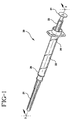
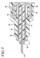
- an operable retracting needle syringe 20 includes a retracting needle assembly 21, a syringe barrel 22 and a plunger 23.
- the barrel includes an inside surface 25 defining a chamber 27, an open proximal end 28 and an open distal end 29 including a cylindrical collar 31 having an outside surface 32 and an inside surface 33.
- the plunger is slidably positioned in fluid-tight engagement with the inside surface of the barrel.
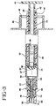
- the plunger includes a proximal portion 37 having a distal end 38 with an elongated cavity 39 therein.
- a release element 43 having a sharp distal edge 44 is positioned at distal end 38 of the proximal portion of plunger 23.
- a hollow distal portion 46 of plunger 23 is releasably connected to proximal portion 37 and capable of telescopic motion with respect to the proximal portion.
- a cover element on the distal portion seals a distal end 47. In this embodiment the cover element is stopper 50. It is preferred that the cover element be made of an elastomeric material selected from the group of thermoplastic elastomers, natural rubber, synthetic rubber and combinations thereof.
- Retracting needle assembly 21 includes an outer hub 53 having a proximal end 55, a distal end 56 and a passageway 57 therethrough.
- the retracting needle assembly also includes an inner hub 61 having a proximal end 62, a distal end 63 and a conduit therethrough 64.
- the inner hub includes an inner portion 65 and a dissociable outer portion 67 connected to the inner portion.
- the dissociable outer portion is connected to outer hub 53.
- Distal end 63 of the inner hub is smaller than passageway 57 of the outer hub at distal end 56 and is accessible therefrom and preferably projects distally outwardly therefrom.
- a needle cannula 71 having a distal end 73, a proximal end 74 and a lumen 75 therethrough.
- the proximal end of the cannula is connected to distal end 63 of the inner hub so that the lumen is in fluid communication with conduit 64 of the inner hub.
- the distal end of the cannula preferably includes a sharp or sharpened distal tip.
- An energized spring is contained between the outer and inner hubs and this preferred embodiment the energized spring is a compressed coil spring 76.
- Various spring types and elastomeric materials and the like can be used to provide a biasing force between the inner and outer hubs with the coil spring being merely representative of these many possibilities all of which are within the purview of the present invention.
- a coil spring is preferred because of its compact size and the ability to easily design the spring to provide the forces necessary for proper operation of the retractable needle assembly.
- the coil spring is placed over the inner portion of the inner hub and then the distal end of the spring is positioned in the outer hub and the inner and outer hubs are moved toward each other to compress the spring and lock together through the action of annular locking projection 70 on the inner hub and annular locking recess 59 in the outer hub.
- annular locking projection on the inner hub snaps into annular locking recess 59 in the outer hub.
- the projection and the recess are shaped so that much less force is required to assemble the components than to reverse the process, thus providing for a permanent locked condition wherein the inner hub and the outer hub are inseparable during normal operating conditions.
- the retracting needle assembly also includes means for connecting the outer hub to the collar of the syringe barrel.
- means for connecting includes structure providing for threadable engagement between the collar and the outer hub.
- the structure for threadable engagement includes at least one thread 58 in passageway 57 of outer hub 53 and at least one thread 34 on outside surface 32 of the cylindrical collar.
- the structure of the preferred embodiment allows the installation and removal of the needle assembly from the barrel using the same motions required for installation and removal of a standard hypodermic needle from a standard hypodermic syringe so that no additional training is required for the health care worker.
- Another important feature of the present invention is providing a retracting needle syringe with low dead space. This means that almost all of the medication in the chamber is expelled from the syringe during the injection process.
- Many prior art retractable and retracting needle syringes have structure protruding into the chamber for holding and/or releasing the retracting or retractable needle. Much of the medication surrounding these structures is lost and will not be delivered because needle retraction will have begun while the medication is still in the barrel.
- the user could begin the needle retracting process while the needle is still within the patient. The needle could still come out of the patient while medication is being delivered and there is a potential for injury to the patient if the needle is moved laterally as the result of the force being applied to initiate the needle retraction process.
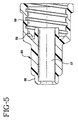
- the preferred embodiment includes a frusto-conically shaped surface 68 at proximal end 62 of the inner hub which is preferably a recess. This surface is adapted to mate a conically-shaped surface 51 on stopper 50. Surface 51 is preferably a projection.
- the distal end of the syringe barrel includes a frusto-conically shaped surface 30 which also approaches and preferably touches the stopper when the plunger is in its distal-most position with respect to delivering medication from the chamber.
- the structure for threadable engagement between the collar and the outer hub can include a wide variety of thread-like and bayonette-type structures including a thread on the outside surface of the collar and a thread follower projection on the inside surface of the outer hub which will follow the collar thread as the hub is screwed onto the collar.
- This structure is similar to the well-known locking luer-type needle assembly and syringe combinations wherein the syringe collar has a thread on its inside surface and the needle assembly has two outwardly directed projections on the base of its hub for allowing the hub follow the threads of the collar as it is screwed onto the luer tip and collar.
- the inside of the collar can be threaded in the outside of the outer hub can have thread followers.
- the preferred embodiment includes tapered cylindrical surface 69 on inner hub 61 and tapered cylindrical surface 35 on the inside of cylindrical collar 31 of the barrel.
- the tapered cylindrical surface 35 on the collar engages tapered cylindrical surface 69 on the inner hub to seal the interface between the hub and the collar to prevent leakage during normal use.
- the present invention provides a clear departure and improvement over the prior art by offering features such as leakage protection without the use of gaskets, and low dead-space in combination with a removable retracting needle assembly.
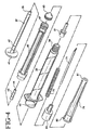
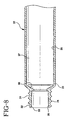
- Retracting needle assembly 21 preferably, but not necessarily, includes an elongated needle shield 79 having an open proximal end 80, a distal end 81 and a sidewall 82 therebetween defining a recess 83 in the shield.
- the shield removably engages the outer hub and covers the needle cannula.
- the shield helps protect the needle cannula from contamination before use.
- the shield preferably frictionally engages portions of outer hub 53.
- the retracting needle assembly of the present invention can be removably connected to syringe barrel 22 containing plunger 23. Needle shield 79 can now be removed from the retracting needle assembly thus exposing the needle cannula for use.
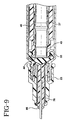
- the retracting needle syringe can be filled using known methods such as withdrawing injectable liquid from a vial having a pierceable stopper. A syringe may then be used to inject liquid into a patient, an I.V. set, a catheter or other suitable device. After the liquid in the chamber is injected or otherwise delivered, the distal end of the stopper will be contacting the distal end of the barrel chamber as best illustrated in Fig. 9.
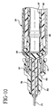
- the user can apply additional distally directed axial force to the proximal end of the plunger to bottom out the stopper on the distal end of the barrel chamber and to cause the disengagement of the proximal portion 37 of the plunger from distal portion 46 of the plunger. Because the connection between the proximal portion of the plunger and the distal portion of the plunger is broken or overcome, the proximal portion will move distally within the distal portion and along the barrel advancing release element 43 so that its sharp distal end will press on and cut through stopper 50 and through the inner hub between inner portion 65 and dissociable outer portion 67, as best illustrated in Fig. 10.
- Another feature of the syringe barrel and plunger of the present invention is proximally facing circular wall 40 on the proximal end of the barrel which is slightly larger than flange 41 on the proximal end of the plunger so that when the plunger reaches its furthest distal position with respect to the barrel, the flange 41 is within the circular wall 40 thus preventing the user from attempting to pull the plunger in a proximal direction in an attempt to re-expose the needle.
- a mechanical interference such as an overlap or snap fit structure can also be provided to further hold the flange inside the circular wall.
- inwardly directed ledge 45 is provided to hold the plunger in the barrel after the needle cannula has been retracted.
- a second groove 48 on the plunger rod can be used to help hold the plunger in the barrel after needle retraction.
- This second groove is preferably used if an inwardly directed ledge or other structure is not used on circular wall 40.
- annular projection 49 on the plunger will engage groove 48 after needle retraction. This engagement will hold the proximal portion of the plunger to the distal portion of the plunger, wherein the distal portion of the plunger will be held in the barrel by the friction of the stopper.
- the releasable connection between proximal portion 37 of the plunger and distal portion 46 of the plunger which allows the telescopic relative motion between the two plunger portions is provided by a snap-fit arrangement between the proximal portion of the plunger and the distal portion of the plunger.
- an annular projection 49 on the inside of the proximal end of the distal portion 46 of the plunger engages an annular groove 42 on the proximal end of proximal portion 37 of the plunger.
- annular projection 49 disengages from annular groove 42 allowing the distal end of the release element to cut through the stopper and the inner hub between the dissociable outer portion and the inner portion.
- connection can also be breakable as well as disengageable such as by use of a frangible adhesive between the two elements or molding the elements as an integral structure containing a brittle plastic projection or projections which join the elements and can be broken with a force applied to the plunger.
- a breakable connection can also be made by connecting the elements with a sheer pin.
- a sheer pin made be made of plastic with one or more notches or stress risers suitably placed to cause breaking at the desired force levels.
- a breakable connection may also be accomplished similar to the snap fit arrangement but designing the various projections and recesses to fail upon reaching the desired stress level.
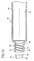
- Fig. 12 illustrates an alternative embodiment of the present invention which functions similarly to the embodiment of Figs. 1-11 except that means for connecting the outer hub to the collar.
- syringe barrel 122 includes an inside surface 125 defining a chamber 127, an open distal end 129, an open proximal end (not shown) and a cylindrical collar 131.
- the cylindrical collar includes an outside surface 132 and an inside surface 133.
- the inside surface includes at least one thread 134.
- a retracting needle assembly 121 includes an outer hub 153 having at least one, and in this preferred embodiment two radially directed outwardly projecting tabs sized and shaped to engage thread 134 so that the retracting needle assembly can be releasably engaged with the syringe barrel through rotational motion of the needle assembly relative to the barrel.
- the outer hub can be attached to the collar using adhesive or ultrasonic welding, retaining clips or a one-way snap-fit arrangement that renders the assembly irreversible under normal use.
- Such structures fall within the purview of the prevent invention.
- a major improvement provided by the present invention is overcoming the aforementioned shortcomings of prior art retractable needle syringes and retractable needles.
- the present invention allows the assembly of the inner and outer hub and the spring before the addition and connection of the sharpened needle cannula. This allows the retracting needle assembly of the present invention to be manufactured in a similar manner to conventional needle assemblies wherein the needle is attached to the finished hub after which there are no further assembly steps but for the application of a needle shield.
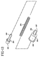
- a method of making an operable retracting needle assembly 221 of the present invention comprises the steps of: providing an outer hub 253 having a proximal end 255, a distal end 256 and a passageway 257 therethrough; providing an inner hub 261 having a proximal end 262, a distal end 263 and a conduit therethrough; providing a needle cannula 271 having a distal end 273, a proximal end 274 and a lumen therethrough; providing a coil compression spring 276; assembling the inner hub, the spring and the outer hub so that the spring is compressed and held within the outer hub by the inner hub being connected to the outer hub so that the distal end of the inner hub is accessible from the passageway at the distal end of the outer hub; position proximal end 274 of cannula 271, (as best illustrated in Fig.
- adhesives are suitable for attaching a cannula to a hub including epoxy adhesives which may be self-curing or curable with heat, ultraviolet light and the like.
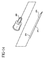
- the method of making an operable retracting needle assembly preferably further includes providing an elongated needle shield 279 and removably connecting the needle shield to outer hub 253 so that the distal end of the needle cannula is in the needle shield.
- the retracting needle assembly may be sealed in a package 288 which functions as a microbial barrier and sterilized along with the package using a method such as radiation sterilization, autoclaving or the like.
- the method of making a retracting needle assembly may also include attaching the needle assembly to a syringe barrel 22 (see Figs. 1-11) having an inside surface 25 defining a chamber 27, an open proximal end 28 and open distal end 29 including a cylindrical collar 31 so that outer hub 253 engages collar 31.
- the method may further include providing a plunger 23 either before or after the retracting needle assembly is attached to the syringe barrel. Preferably, this step occurs first before the attachment of the retracting needle assembly.
- This step includes providing a plunger 23 slidably positioned in fluid-tight engagement with the inside surface of said syringe barrel.
- the retracting needle syringe may be sealed in a package 289 which function as a microbial barrier and the package along with the retracting needle syringe is sterilized using a method such as radiation sterilization, autoclaving or the like.
- the present invention offers a major advantage over the prior art by allowing the needle cannula to be assembled to the retracting needle assembly after the components of the needle assembly have been assembled thereby greatly reducing any potential for damaging the fragile needle tip during the assembly process.
Abstract
Description
wherein distal motion of said plunger with respect to said barrel will cause said proximal portion of said plunger to separate from said distal portion of said plunger allowing said proximal portion to move distally so that said release element contacts and cuts through said cover element and said inner hub disconnecting said dissociable outer portion from said inner portion and allowing said spring to move said needle cannula far enough into said cavity of said proximal portion so that the distal end of the cannula is positioned proximally of the distal end of said outer hub.
Claims (9)
- An operable retracting needle syringe (20) including:characterised in that said distal end (63) of said inner hub (61) is smaller than said passageway (57) of said outer hub (53) at said distal end (56) of said outer hub (53) and projects distally outwardly therefrom; anda syringe barrel (22) having an inside surface (25) defining a chamber (27), an open proximal end (28) and an open distal end (29) including a cylindrical collar (31);an outer hub (53) having a proximal end (55), a distal end (56) and apassageway (57) therethrough;an inner hub (61) having a proximal end (62), a distal end (63) and a conduit (64) therethrough, said proximal end (62) of said inner hub (61) having an inner portion (65) and a dissociable outer portion (67) connected to said inner portion (65), said dissociable outer portion (67) connected to said outer hub (53);a needle cannula (71) having a distal end (73), a proximal end (74), and a lumen (75) therethrough, said proximal end (74) of said cannula (71) being connected to said distal end (63) of said inner hub (61) so that said lumen (75) is in fluid communication with said conduit (64);a plunger (23) slidably positioned in fluid-tight engagement with said inside surface (25) of said barrel (22), said plunger (23) including a proximal portion (37) having a distal end (38) with an elongated cavity (39) therein, a release element (43) having a sharp distal edge (44) positioned at said distal end (38) of said proximal portion (37), and a cover element (50) on a distal end (47) of said distal portion sealing said distal end (47) of said distal portion;said plunger (23) has a hollow distal portion (46) releasably connected to said proximal portion (37) and capable of telescopic motion with respect to said proximal portion (37);an energized spring (76) contained between said outer hub (53) and said inner hub (61);means (58, 34) for connecting said outer hub (53) to the collar (31) of a syringe barrel (22); and
wherein distal motion of said plunger (23) with respect to said barrel (22) will cause said proximal portion (37) of said plunger (23) to separate from said distal portion of said plunger (23) allowing said proximal portion (37) to move distally so that said release element (43) contacts and cuts through said cover element (50) and said inner hub (61) disconnecting said dissociable outer portion (67) from said inner portion (65) and allowing said spring (76) to move said needle cannula (71) far enough into said cavity (39) of said proximal portion (37) so that the distal end (73) of the cannula (71) is positioned proximally of the distal end (56) of said outer hub (53). - The assembly of Claim 1 further including an elongated needle shield (79) removably engaging said outer hub (53) and covering said needle cannula (71).
- The assembly of Claim 1 wherein said energized spring is a compressed coil spring (76).
- The assembly of Claim 1 wherein the cylindrical collar (31) has an outside surface (32) and an inside surface (33), said outer hub (53) being connected to said collar (31) so that said cannula (71) projects distally outwardly from said syringe barrel (22).
- The assembly of Claim 4 wherein said means (58, 34) for connecting said outer hub to said collar includes structure for threadable engagement between said collar and said outer hub.
- The assembly of Claim 5 wherein said structure for threadable engagement includes structure on the outside of said collar and in said passageway of said outer hub.
- The assembly of Claim 4 wherein said inner hub (61) includes a frusto-conically-shaped surface (68) adapted to mate with a frusto-conically-shaped surface in said collar (51) for helping to prevent leakage through the interface of said inner hub (61) and said collar.
- The assembly of Claim 1 wherein said cover element is a stopper (50) having a side portion which contacts said inside surface of said barrel.
- The assembly of Claim 1wherein said cover element (50) further includes a projection (51) extending outwardly from said cover element, sized and shaped to fit inside a recess in said inner hub.
Priority Applications (3)
| Application Number | Priority Date | Filing Date | Title |
|---|---|---|---|
| DK03005683T DK1323447T3 (en) | 1999-10-15 | 2000-08-10 | Spray with retractable needle |
| DK00117127T DK1092443T3 (en) | 1999-10-15 | 2000-08-10 | Spray with retractable needle |
| EP03005683A EP1323447B1 (en) | 1999-10-15 | 2000-08-10 | Retracting needle syringe |
Applications Claiming Priority (2)
| Application Number | Priority Date | Filing Date | Title |
|---|---|---|---|
| US09/419,184 US6368303B1 (en) | 1999-10-15 | 1999-10-15 | Retracting needle syringe |
| US419184 | 1999-10-15 |
Related Child Applications (2)
| Application Number | Title | Priority Date | Filing Date |
|---|---|---|---|
| EP03005683A Division EP1323447B1 (en) | 1999-10-15 | 2000-08-10 | Retracting needle syringe |
| EP03005683.2 Division-Into | 2003-03-13 |
Publications (3)
| Publication Number | Publication Date |
|---|---|
| EP1092443A2 EP1092443A2 (en) | 2001-04-18 |
| EP1092443A3 EP1092443A3 (en) | 2002-04-03 |
| EP1092443B1 true EP1092443B1 (en) | 2005-06-01 |
Family
ID=23661160
Family Applications (2)
| Application Number | Title | Priority Date | Filing Date |
|---|---|---|---|
| EP03005683A Expired - Lifetime EP1323447B1 (en) | 1999-10-15 | 2000-08-10 | Retracting needle syringe |
| EP00117127A Expired - Lifetime EP1092443B1 (en) | 1999-10-15 | 2000-08-10 | Retracting needle syringe |
Family Applications Before (1)
| Application Number | Title | Priority Date | Filing Date |
|---|---|---|---|
| EP03005683A Expired - Lifetime EP1323447B1 (en) | 1999-10-15 | 2000-08-10 | Retracting needle syringe |
Country Status (13)
| Country | Link |
|---|---|
| US (2) | US6368303B1 (en) |
| EP (2) | EP1323447B1 (en) |
| JP (1) | JP4312368B2 (en) |
| CN (1) | CN1243575C (en) |
| AT (2) | ATE296651T1 (en) |
| AU (1) | AU779820B2 (en) |
| BR (1) | BR0004721B1 (en) |
| CA (1) | CA2316064C (en) |
| DE (2) | DE60020479T2 (en) |
| DK (2) | DK1323447T3 (en) |
| ES (2) | ES2243179T3 (en) |
| MX (1) | MXPA00010073A (en) |
| NZ (1) | NZ506456A (en) |
Cited By (1)
| Publication number | Priority date | Publication date | Assignee | Title |
|---|---|---|---|---|
| US7862547B2 (en) | 1999-11-04 | 2011-01-04 | Tyco Healthcare Group Lp | Safety shield for medical needles |
Families Citing this family (119)
| Publication number | Priority date | Publication date | Assignee | Title |
|---|---|---|---|---|
| US6843781B2 (en) * | 1999-10-14 | 2005-01-18 | Becton, Dickinson And Company | Intradermal needle |
| US6280420B1 (en) | 1999-11-04 | 2001-08-28 | Specialized Health Products | Reaccessible medical needle safety devices and methods |
| US8226617B2 (en) | 1999-11-04 | 2012-07-24 | Tyco Healthcare Group Lp | Safety shield apparatus and mounting structure for use with medical needle devices |
| US20030050605A1 (en) * | 1999-12-08 | 2003-03-13 | John Targell | Closure assembly in particular for hypodermic syringes |
| OA11679A (en) * | 2000-01-26 | 2005-01-12 | Tecnedil Srl | Improved disposable syringe with a retractable needle. |
| US6475194B2 (en) * | 2000-04-05 | 2002-11-05 | Gem Plastics, Inc. | Safety syringe |
| US6592555B1 (en) * | 2000-06-23 | 2003-07-15 | Wang Wen-Pi | Syringe device |
| US6599268B1 (en) * | 2000-06-27 | 2003-07-29 | Becton Dickinson And Company | Hypodermic syringe with a selectively retractable needle |
| US6585690B1 (en) * | 2000-06-29 | 2003-07-01 | Becton Dickinson And Company | Hypodermic syringe with selectivity retractable needle |
| US6689106B2 (en) * | 2000-07-31 | 2004-02-10 | Becton Dickinson And Company | Retracting needle assembly for a syringe |
| US6413237B1 (en) * | 2000-08-31 | 2002-07-02 | Becton, Dickinson And Company | Hypodermic syringe with selectively retractable needle |
| US6511459B1 (en) * | 2000-09-29 | 2003-01-28 | Mallinckrodt Inc. | Syringe plunger having an improved sealing ability |
| US7544189B2 (en) * | 2000-10-10 | 2009-06-09 | Meridian Medical Technologies, Inc. | Needle and hub assembly for automatic injector |
| US7621887B2 (en) * | 2000-10-10 | 2009-11-24 | Meridian Medical Technologies, Inc. | Wet/dry automatic injector assembly |
| AUPR131000A0 (en) * | 2000-11-09 | 2000-11-30 | Southern Dental Industries Limited | A dental cartridge |
| AUPR373001A0 (en) * | 2001-03-14 | 2001-04-12 | Glenord Pty Ltd | Improved non-reusable syringe |
| US6800066B2 (en) * | 2001-04-26 | 2004-10-05 | Nmt Group Plc | Retractable needle syringe |
| AU2002223385B2 (en) * | 2001-07-20 | 2007-01-25 | Medicalchain International Corp. | An automatically retractable safety syringe |
| US20030040720A1 (en) * | 2001-08-22 | 2003-02-27 | Steube Gregory Alan | Needle hub assembly |
| US6835190B2 (en) * | 2002-04-17 | 2004-12-28 | Smiths Medical Asd, Inc. | Retractable safety infusion needle |
| DK1747789T3 (en) * | 2002-07-03 | 2009-11-30 | Novo Nordisk As | Needle mounting means and use of the needle mounting means for mounting a needle assembly |
| US7654986B2 (en) | 2002-07-03 | 2010-02-02 | Novo Nordisk A/S | Needle mounting system and a method for mounting a needle assembly |
| US6905485B2 (en) * | 2003-02-19 | 2005-06-14 | Becton, Dickinson And Company | Medical device with needle safety shielding |
| US20040176705A1 (en) * | 2003-03-04 | 2004-09-09 | Stevens Timothy A. | Cartridge having an integrated collection element for point of care system |
| US20040176704A1 (en) * | 2003-03-04 | 2004-09-09 | Stevens Timothy A | Collection device adapted to accept cartridge for point of care system |
| US7452324B2 (en) * | 2003-04-16 | 2008-11-18 | Mallinckrodt Inc. | Radiation shield for a safety syringe having a needle sheath |
| JP4289919B2 (en) * | 2003-05-06 | 2009-07-01 | 朝日インテック株式会社 | Chemical injection device |
| US7037292B2 (en) * | 2003-06-27 | 2006-05-02 | Sherwood Services Ag | Safety needle shield apparatus |
| IL157984A (en) | 2003-09-17 | 2015-02-26 | Dali Medical Devices Ltd | Autoneedle |
| IL157981A (en) | 2003-09-17 | 2014-01-30 | Elcam Medical Agricultural Cooperative Ass Ltd | Auto-injector |
| GB2410188B (en) | 2004-01-23 | 2006-01-25 | Medical House Plc | Injection device |
| GB2410190A (en) * | 2004-01-26 | 2005-07-27 | Medical House Plc | Disposable gas-powered needle-free injection device |
| US8002745B2 (en) * | 2004-01-28 | 2011-08-23 | Unitract Syringe Pty Ltd. | Retractable syringe with plunger disabling system |
| IL160891A0 (en) | 2004-03-16 | 2004-08-31 | Auto-mix needle | |
| SE0401569D0 (en) * | 2004-06-17 | 2004-06-17 | Gambro Lundia Ab | applicator |
| MX2007001726A (en) * | 2004-08-13 | 2007-04-20 | Becton Dickinson Co | Retractable needle syringe assembly. |
| CA2584106C (en) * | 2004-10-14 | 2011-09-06 | Safety Medical International, Incorporated | Safety medical syringe with retractable needle |
| WO2006111806A2 (en) * | 2005-02-07 | 2006-10-26 | Indigo Orb, Inc. | Safety syringes |
| US8062252B2 (en) * | 2005-02-18 | 2011-11-22 | Becton, Dickinson And Company | Safety shield system for a syringe |
| JP4622876B2 (en) * | 2005-03-24 | 2011-02-02 | 株式会社ジェイ・エム・エス | Indwelling needle device |
| US7740636B2 (en) * | 2005-04-15 | 2010-06-22 | Abbott Medical Optics Inc. | Multi-action device for inserting an intraocular lens into an eye |
| CN100544784C (en) * | 2005-04-26 | 2009-09-30 | 刘文杰 | The barrel type push bar of needle retraction type syringe and needle retractable controllable type syringe |
| US20060264840A1 (en) * | 2005-05-09 | 2006-11-23 | Daniel Thayer | Syringe |
| US7947020B2 (en) * | 2005-05-09 | 2011-05-24 | Safeshot Technologies, Llc | Retractable safety syringe |
| GB0601309D0 (en) | 2006-01-23 | 2006-03-01 | Medical House The Plc | Injection device |
| US20070173770A1 (en) * | 2006-01-23 | 2007-07-26 | The Medical House Plc | Injection device |
| TWI294782B (en) * | 2006-01-27 | 2008-03-21 | Bencha Internat Group Inc | Medically safety injector with a collapsable plunger combination thereof |
| AU2007227200B2 (en) | 2006-03-21 | 2013-01-24 | Covidien Lp | Passive latch ring safety shield for injection devices |
| US20070250003A1 (en) * | 2006-04-03 | 2007-10-25 | Bare Rex O | Fluid activated retractable safety syringe |
| US7972301B2 (en) | 2006-04-03 | 2011-07-05 | Safeshot Technologies, Llc | Safety needle syringe braking system |
| CN100408120C (en) * | 2006-04-05 | 2008-08-06 | 刘文杰 | Changeable needle structure of needle retraction type injector, and said injector |
| US7806858B2 (en) * | 2006-04-19 | 2010-10-05 | Safeshot Technologies, Llc | Vacuum actuated small volume syringe |
| US8152762B2 (en) * | 2006-04-20 | 2012-04-10 | Safeshot Technologies, Llc | Plunger activated vacuum release mechanism for a syringe |
| US20080114307A1 (en) * | 2006-11-06 | 2008-05-15 | Jeffrey Smith | Puncturable membrane for safety syringe |
| US8398601B2 (en) * | 2006-11-06 | 2013-03-19 | Safeshot Technologies, Llc | Puncturable membrane for safety syringe |
| US20080097306A1 (en) * | 2006-08-29 | 2008-04-24 | Jeffrey Smith | Sterilized syringe |
| US7972300B2 (en) * | 2006-05-05 | 2011-07-05 | Safeshot Technologies, Llc | Syringe |
| US8088104B2 (en) * | 2006-05-24 | 2012-01-03 | Safeshot Technologies, Llc | Syringe |
| US20080033347A1 (en) * | 2006-08-03 | 2008-02-07 | Becton, Dickinson And Company | Detachable needle syringe having reduced dead space |
| US20080033370A1 (en) | 2006-08-03 | 2008-02-07 | Becton, Dickinson And Company | Binary needle attachment mechanisms |
| US7637889B2 (en) * | 2006-11-15 | 2009-12-29 | Glynntech, Inc. | Drug delivery device with sliding valve and methodology |
| ITMI20062190A1 (en) | 2006-11-15 | 2008-05-16 | Amendola Carlo | DISPOSABLE SYRINGE OF PERFECT TYPE |
| US8088110B2 (en) * | 2006-11-17 | 2012-01-03 | Bencha International Group Inc. | Automatically retractable safety injector for non-liquid material |
| US8382713B2 (en) * | 2006-12-11 | 2013-02-26 | Kenergy Scientific, Inc. | Drug delivery device and methodology |
| GB0625169D0 (en) | 2006-12-18 | 2007-01-24 | Medical House Plc The | Improved autoinjector |
| US20080154212A1 (en) * | 2006-12-26 | 2008-06-26 | Stat Medical Devices, Inc. | Syringe with retractable needle support |
| GB0704351D0 (en) | 2007-03-07 | 2007-04-11 | Medical House Plc The | Improved autoinjector |
| JP5362591B2 (en) * | 2007-03-09 | 2013-12-11 | イーライ リリー アンド カンパニー | Delay mechanism for automatic injection equipment |
| US8095870B2 (en) * | 2007-06-06 | 2012-01-10 | Oracle International Corporation | Extensible document transformation language: an innovative way of generating business document and report |
| USD675316S1 (en) * | 2007-08-22 | 2013-01-29 | Novo Nordisk A/S | Needle hub |
| GB0721774D0 (en) * | 2007-11-07 | 2007-12-19 | 3M Innovative Properties Co | one-piece vented piston |
| US8172813B2 (en) * | 2008-02-28 | 2012-05-08 | Becton, Dickinson And Company | Syringe with two piece plunger rod |
| US7976510B2 (en) | 2008-02-28 | 2011-07-12 | Becton, Dickinson And Company | Syringe with adjustable two piece plunger rod |
| BRPI0908311B8 (en) * | 2008-05-08 | 2021-06-22 | Shantou Wealy Medical Instr Co Ltd | disposable self-destruct safety syringe with no residual fluid |
| US7785296B2 (en) | 2008-07-17 | 2010-08-31 | Smiths Medical Asd, Inc. | Needle tip spring protector |
| CN101480511B (en) * | 2009-02-08 | 2011-10-05 | 浙江康康医疗器械有限公司 | Disposable safety syringe with syringe needle capable of automatically retracting |
| US8986249B2 (en) * | 2009-04-08 | 2015-03-24 | Stat Medical Devices, Inc. | Retractable needle assembly and syringe utilizing the same |
| US9480799B2 (en) * | 2009-04-08 | 2016-11-01 | Stat Medical Devices, Inc. | Retractable needle assembly utilizing a standard interface and syringe utilizing the same |
| US20110125130A1 (en) * | 2009-04-08 | 2011-05-26 | Stat Medical Devices, Inc. | Retractable needle assembly and syringe utilizing the same |
| GB2469672B (en) | 2009-04-23 | 2013-09-25 | Medical House Ltd | Improved autoinjector |
| US9145253B2 (en) | 2009-08-04 | 2015-09-29 | 3M Innovative Properties Company | Dispensing device with pressure release |
| JP2011136153A (en) * | 2009-10-19 | 2011-07-14 | Terumo Medical Corp | Kit with syringe assembly |
| USD658763S1 (en) | 2010-02-02 | 2012-05-01 | 3M Innovative Properties Company | Dental capsule |
| PL2708252T3 (en) | 2010-03-01 | 2016-01-29 | Lilly Co Eli | Automatic injection device with delay mechanism including dual functioning biasing member |
| US9320856B2 (en) | 2010-05-07 | 2016-04-26 | Intuitive Creations Pte. Ltd. | Syringe assembly and a needle unit for attachment to a syringe unit to form a syringe assembly |
| EP2566542A4 (en) | 2010-05-07 | 2015-09-16 | Intuitive Creations Pte Ltd | A retractable syringe with a cutting crown |
| US8333737B2 (en) | 2010-06-03 | 2012-12-18 | Jms North America Corporation | Systems and methods for a medical syringe |
| US9550030B2 (en) | 2010-07-22 | 2017-01-24 | Becton, Dickinson And Company | Dual chamber syringe with retractable needle |
| US8721599B2 (en) | 2010-07-22 | 2014-05-13 | Becton, Dickinson And Company | Dual chamber passive retraction needle syringe |
| US8556855B2 (en) | 2010-07-22 | 2013-10-15 | Becton, Dickinson And Company | Dual chamber syringe with retractable needle |
| US8556854B2 (en) | 2010-07-22 | 2013-10-15 | Becton, Dickinson And Company | Dual chamber syringe with retractable needle |
| US8277422B2 (en) | 2010-07-23 | 2012-10-02 | Safeshot Technologies, Llc | Multi-chambered retractable safety syringe |
| WO2012023938A1 (en) | 2010-08-19 | 2012-02-23 | West Pharmaceutical Services, Inc. | Rigid needle shield |
| USD665498S1 (en) * | 2011-01-11 | 2012-08-14 | Fuso Pharmaceutical Industries, Ltd. | Gasket for injector |
| ES2710905T3 (en) | 2011-01-24 | 2019-04-29 | E3D Agricultural Coop Association Ltd | Injector |
| US8657793B2 (en) | 2011-09-30 | 2014-02-25 | Becton Dickinson France, S.A.S | Space saving plunger cap and rod assembly |
| MX366271B (en) | 2011-11-07 | 2019-07-04 | Safety Syringes Inc | Contact trigger release needle guard. |
| US8784376B2 (en) | 2012-12-04 | 2014-07-22 | Becton, Dickinson And Company | Thumb press frangible feature for re-use prevention |
| US10780229B2 (en) | 2013-03-07 | 2020-09-22 | David B. Brothers | Low waste syringe and needle assemblage |
| CA2908822C (en) | 2013-03-07 | 2019-05-07 | David B. Brothers | Low waste syringe and needle assemblage |
| CA2899558A1 (en) | 2013-03-14 | 2014-10-02 | Eli Lilly And Company | Delay mechanism suitable for compact automatic injection device |
| CN105025957A (en) | 2013-03-14 | 2015-11-04 | 伊莱利利公司 | Trigger assembly for an automatic injection device |
| WO2014179599A1 (en) * | 2013-05-03 | 2014-11-06 | Chen Rayfu | Auto-retractable safety syringe |
| EP3043830A1 (en) | 2013-09-09 | 2016-07-20 | Covidien LP | Sealed self-activating injecton device for delivery of medicine from a prefilled cartridge or vial |
| WO2015035378A1 (en) * | 2013-09-09 | 2015-03-12 | Covidien Lp | Single-use device for injection of cartridge drugs |
| US9937299B2 (en) | 2013-09-26 | 2018-04-10 | Becton, Dickinson And Company | Adjustable penetration depth syringe |
| US9078977B2 (en) | 2013-09-30 | 2015-07-14 | Becton, Dickinson And Company | Dual shielded syringe |
| USD747797S1 (en) | 2013-11-14 | 2016-01-19 | Eli Lilly And Company | Injection device |
| GB2522656A (en) * | 2014-01-31 | 2015-08-05 | Consort Medical Plc | Improved syringe for autoinjector device |
| US9555221B2 (en) | 2014-04-10 | 2017-01-31 | Smiths Medical Asd, Inc. | Constant force hold tip protector for a safety catheter |
| USD814630S1 (en) * | 2014-09-09 | 2018-04-03 | Covidien Lp | Syringe |
| CN107106280A (en) | 2014-12-23 | 2017-08-29 | 奥特梅德私人有限公司 | Conveying equipment, system and associated method |
| JP6635698B2 (en) * | 2015-07-14 | 2020-01-29 | ぺんてる株式会社 | Applicator with limited plunger movable range by resistance structure |
| USD823460S1 (en) * | 2015-12-08 | 2018-07-17 | Glenmark Pharmaceuticals S.A. | Anal device |
| KR102165159B1 (en) * | 2018-03-28 | 2020-11-04 | (주) 에스엔제이 | disposable safety syringe |
| EP3821925B1 (en) * | 2019-09-18 | 2024-03-20 | KAISHA PACKAGING Private Ltd. | Device for locking a plunger rod of a syringe after use and preventing re-use of the syringe, and syringe assembly |
| WO2021163004A1 (en) * | 2020-02-14 | 2021-08-19 | Merck Sharp & Dohme Corp. | Patient training device for use with a safety syringe injector |
| USD986413S1 (en) | 2021-07-23 | 2023-05-16 | Eli Lilly And Company | Drug delivery device |
| CA211897S (en) * | 2021-10-18 | 2024-03-04 | Tellgen Corp | Pcr tube assembly |
Family Cites Families (83)
| Publication number | Priority date | Publication date | Assignee | Title |
|---|---|---|---|---|
| IT1273192B (en) | 1994-05-10 | 1997-07-07 | Musetta Angela | DISPOSABLE SAFETY SYRINGE |
| US4233975A (en) | 1978-10-04 | 1980-11-18 | Yerman Arthur J | Anti-drug abuse single-use syringe |
| US4687467A (en) | 1986-06-11 | 1987-08-18 | C.T.F. Research Company | One-time use medical syringe invention |
| GB2197792A (en) | 1986-11-26 | 1988-06-02 | Power Richard Kiteley | Disposable syringes |
| US4900307A (en) | 1987-04-29 | 1990-02-13 | Kulli John C | Safety retracting needle for use with syringe |
| US4927414A (en) | 1987-04-29 | 1990-05-22 | Kulli John C | Syringe with safety retracting needle |
| IN169618B (en) | 1987-06-25 | 1991-11-23 | Agven Medical Corp Ltd | |
| US5011476A (en) | 1987-07-01 | 1991-04-30 | Foster Robert J C | Single fill and use syringe |
| DK156414C (en) | 1987-07-13 | 1990-01-22 | Gerda Ingrid Maria Gaarde | INJECTIVE SPRAY WITH CANNEL THAT CAN BE WITHDRAWED AND FIXED IN THE SPRAY |
| US4838869A (en) | 1987-08-29 | 1989-06-13 | Allard Edward F | Retractable needle syringe |
| US4838863A (en) | 1987-09-21 | 1989-06-13 | Allard Edward F | Safe needle system for collecting fluids |
| US4955870A (en) | 1988-08-23 | 1990-09-11 | Ridderheim Kristen A | Hypodermic syringe with retractable needle |
| US4929237A (en) | 1988-11-07 | 1990-05-29 | David Medway | Hypodermic needle protection device |
| US5013301A (en) | 1988-11-18 | 1991-05-07 | Marotta Jr Phillip | Syringe holder |
| IT1227658B (en) | 1988-12-01 | 1991-04-23 | Vittorio Boschetti B | DISPOSABLE SYRINGE WITH RETURN AND NEEDLE LOCK AT THE END OF INJECTION FOR THE PURPOSE OF AVOID RE-USE |
| IT1225440B (en) | 1988-12-07 | 1990-11-13 | Nacci Gaetano | PISTON FOR SYRINGES THAT AUTOMATICALLY MAKES THE HYPODERMIC NEEDLE, MODIFIED PURPOSE, AFTER USE |
| ES2019792A6 (en) | 1990-01-17 | 1991-07-01 | Caralt Batlle Jaime | Disposable hypodermic syringe. |
| ES2009709A6 (en) | 1989-01-24 | 1989-10-01 | Villar Pascual Jose Antonio | Single-use safety syringe |
| US4966593A (en) | 1989-03-06 | 1990-10-30 | Design Specialties Laboratories | Disposable hypodermic syringe with retractable needle |
| US5045063A (en) | 1989-05-30 | 1991-09-03 | Spielberg Alissa R | Hypodermic syringe |
| US4946446A (en) | 1989-06-14 | 1990-08-07 | Vadher Dinesh L | Retractable needle |
| US5407431A (en) | 1989-07-11 | 1995-04-18 | Med-Design Inc. | Intravenous catheter insertion device with retractable needle |
| US4994034A (en) | 1989-07-11 | 1991-02-19 | Botich Michael J | Retractable needle hypodermic syringe system |
| US6096005A (en) * | 1989-07-11 | 2000-08-01 | Mdc Investment Holdings, Inc. | Retractable needle medical devices |
| US5188599A (en) | 1989-07-11 | 1993-02-23 | Med-Design, Inc. | Retractable needle system |
| US5084018A (en) | 1989-08-14 | 1992-01-28 | Tsao Chien Hua | Safety syringe |
| US5019044A (en) | 1989-08-14 | 1991-05-28 | Tsao Chien Hua | Safety hypodermic syringe |
| US5046508A (en) | 1989-12-19 | 1991-09-10 | Jonathan Weissler | Syringe with retractable needle |
| US4973316A (en) | 1990-01-16 | 1990-11-27 | Dysarz Edward D | One handed retractable safety syringe |
| ES2074168T3 (en) | 1990-03-08 | 1995-09-01 | Blue Star Corp Sa | SELF-SWEEPING NEEDLE SYRINGE. |
| US5085640A (en) | 1990-04-06 | 1992-02-04 | Gibbs Andrew H | Non-reusable medical needle apparatus |
| US5053010A (en) | 1990-10-03 | 1991-10-01 | Triad Technology | Safety syringe with retractable needle |
| US5376080A (en) | 1991-01-30 | 1994-12-27 | Petrussa; Gian L. | Single use retractable needle syringe |
| US5092853A (en) | 1991-02-04 | 1992-03-03 | Couvertier Ii Douglas | Automatic retractable medical needle and method |
| US5267961A (en) | 1991-04-03 | 1993-12-07 | Shaw Thomas J | Nonreusable syringe with safety indicator |
| GB9107647D0 (en) | 1991-04-11 | 1991-05-29 | Jeffrey Peter | Syringe construction providing needle point protection |
| EP0515766B1 (en) | 1991-05-29 | 1994-08-24 | Paolo Caselli | Security syringe with retractable hollow needle |
| ES1017717Y (en) | 1991-05-30 | 1993-12-16 | Serrano Gonzalez | SELF-RETRACTILE HYPODERMIC NEEDLE PROTECTOR. |
| US5232447A (en) | 1991-08-08 | 1993-08-03 | Jetfill, Inc. | Non-reusable syringe |
| US5211629A (en) | 1991-12-23 | 1993-05-18 | Pressly William B S | Safety syringe |
| US5613952A (en) | 1991-12-23 | 1997-03-25 | Syringe Develpoment Partners | Safety syringe |
| US5180369A (en) | 1992-01-20 | 1993-01-19 | Dysarz Edward D | Self destructive safety syringe |
| US5188597A (en) | 1992-04-13 | 1993-02-23 | Becton, Dickinson And Company | Safety needle syringe |
| IL105706A (en) | 1992-05-15 | 1996-10-16 | Safe T Ltd | Hollow needle applicator |
| US5180370A (en) | 1992-05-18 | 1993-01-19 | Gillespie Elgene R | Safety hypodermic syringe with retractable needle |
| US5531694A (en) | 1993-08-31 | 1996-07-02 | Clemens; Anton H. | Needle retraction system |
| US5562629A (en) | 1993-08-31 | 1996-10-08 | Haughton; Victor M. | Catheter placement system utilizing a handle, a sharp, and a releasable retainer mechanism providing retraction of the sharp upon disengagement of the catheter from the handle |
| US5395337A (en) | 1993-08-31 | 1995-03-07 | Clemens; Anton H. | Needle retraction system |
| US5385551A (en) | 1993-09-22 | 1995-01-31 | Shaw; Thomas J. | Nonreusable medical device with front retraction |
| WO1995011713A1 (en) | 1993-10-28 | 1995-05-04 | Lok-Tek Syringe Pty Ltd | Hypodermic syringe with retractable needle mount |
| CA2135706C (en) | 1993-11-15 | 1999-06-15 | Walter E. Cover | Retractable-needle cannula insertion set with refinements to better control leakage, retraction speed, and reuse |
| US5634909A (en) | 1993-12-09 | 1997-06-03 | Schmitz; William L. | Auto-retracting needle injector system |
| US5423758A (en) | 1993-12-16 | 1995-06-13 | Shaw; Thomas J. | Retractable fluid collection device |
| US5573510A (en) | 1994-02-28 | 1996-11-12 | Isaacson; Dennis R. | Safety intravenous catheter assembly with automatically retractable needle |
| US5389076A (en) | 1994-04-05 | 1995-02-14 | Shaw; Thomas J. | Single use medical device with retraction mechanism |
| CZ287479B6 (en) | 1994-08-18 | 2000-12-13 | Nmt Group Plc | Syringe with retractable needle |
| US5533970A (en) | 1994-09-28 | 1996-07-09 | Becton, Dickinson And Company | Retractable needle syringe |
| US5480385A (en) | 1995-01-10 | 1996-01-02 | Specialized Health Products, Inc. | Self retracting medical needle apparatus and methods |
| US5637092A (en) | 1995-01-30 | 1997-06-10 | Shaw; Thomas J. | Syringe plunger locking assembly |
| US5632733A (en) | 1995-05-11 | 1997-05-27 | Shaw; Thomas J. | Tamperproof retractable syringe |
| US5578011A (en) | 1995-05-11 | 1996-11-26 | Shaw; Thomas J. | Tamperproof retractable syringe |
| US6090077A (en) * | 1995-05-11 | 2000-07-18 | Shaw; Thomas J. | Syringe plunger assembly and barrel |
| US5685863A (en) | 1995-08-15 | 1997-11-11 | Mdc Investment Holdings Inc. | Retractable needle apparatus for transmission of intravenous fluids |
| DE69628048T2 (en) | 1995-08-22 | 2004-03-18 | MDC Investment Holdings, Inc., Wilmington | PRE-FILLED INJECTION Vials WITH WITHDRAWABLE NEEDLE |
| IT1279684B1 (en) | 1995-11-10 | 1997-12-16 | Claudio Freschi | SYRINGE FOR HYPODERMIC INJECTIONS. |
| US5605544A (en) | 1996-02-12 | 1997-02-25 | Tsao; Chien-Hua | Safety injector with returnable needle |
| US5643211A (en) | 1996-02-29 | 1997-07-01 | Medi-Ject Corporation | Nozzle assembly having a frangible plunger |
| US5665075A (en) | 1996-07-03 | 1997-09-09 | Becton, Dickinson And Company | Method of making a needle shield assembly |
| US5921961A (en) | 1996-09-13 | 1999-07-13 | Mcgary; R. Kern | Non-reusable retractable safety syringe |
| US5769822A (en) * | 1996-09-13 | 1998-06-23 | Mcgary; R. Kern | Non-reusable retractable safety syringe |
| US5681292A (en) | 1996-10-29 | 1997-10-28 | Retrax Safety Systems, Inc. | Retractable needle and syringe combination |
| US5782803A (en) | 1996-11-26 | 1998-07-21 | Jentzen; S. William | Low dead space, interchangeable needle syringe |
| US5800395A (en) | 1996-12-05 | 1998-09-01 | Mdc Investment Holdings, Inc. | Medical device with retractable needle |
| US6004278A (en) | 1996-12-05 | 1999-12-21 | Mdc Investment Holdings, Inc. | Fluid collection device with retractable needle |
| US5885257A (en) | 1997-03-18 | 1999-03-23 | Badger; Peter | Spring loaded automatic retractable needle syringe |
| US5882342A (en) | 1997-04-11 | 1999-03-16 | Safety Medical Manufacturing, Inc | Safety medical syringe with retractable needle |
| US5935104A (en) | 1998-08-21 | 1999-08-10 | Safety Medical Manufacturing, Incorporated | Safety medical syringe with retractable needle |
| AU1609500A (en) * | 1998-11-06 | 2000-05-29 | Mdc Investment Holdings, Inc. | Pre-filled retractable needle injection device |
| US6036674A (en) * | 1998-12-18 | 2000-03-14 | Becton Dickinson And Company | Retracting needle syringe |
| US6010486A (en) | 1998-12-18 | 2000-01-04 | Becton Dickinson And Company | Retracting needle syringe |
| US5984898A (en) | 1999-02-17 | 1999-11-16 | Retrax Safety Systems Inc. | Retractable needle and syringe combination |
| US6099500A (en) * | 1999-12-03 | 2000-08-08 | Dysarz; Edward D. | Safety needle cannula module that is activated by a safety syringe and plunger module |
| US6183440B1 (en) * | 2000-05-25 | 2001-02-06 | Becton, Dickinson And Company | Hypodermic syringe having a selectively retractable needle |
-
1999
- 1999-10-15 US US09/419,184 patent/US6368303B1/en not_active Expired - Lifetime
-
2000
- 2000-08-10 ES ES00117127T patent/ES2243179T3/en not_active Expired - Lifetime
- 2000-08-10 EP EP03005683A patent/EP1323447B1/en not_active Expired - Lifetime
- 2000-08-10 DK DK03005683T patent/DK1323447T3/en active
- 2000-08-10 DE DE60020479T patent/DE60020479T2/en not_active Expired - Fee Related
- 2000-08-10 ES ES03005683T patent/ES2266660T3/en not_active Expired - Lifetime
- 2000-08-10 AT AT00117127T patent/ATE296651T1/en not_active IP Right Cessation
- 2000-08-10 DK DK00117127T patent/DK1092443T3/en active
- 2000-08-10 DE DE60028423T patent/DE60028423T2/en not_active Expired - Lifetime
- 2000-08-10 EP EP00117127A patent/EP1092443B1/en not_active Expired - Lifetime
- 2000-08-10 AT AT03005683T patent/ATE327791T1/en not_active IP Right Cessation
- 2000-08-16 CA CA002316064A patent/CA2316064C/en not_active Expired - Lifetime
- 2000-08-22 NZ NZ506456A patent/NZ506456A/en not_active IP Right Cessation
- 2000-08-30 AU AU55011/00A patent/AU779820B2/en not_active Expired
- 2000-10-09 BR BRPI0004721-0A patent/BR0004721B1/en not_active IP Right Cessation
- 2000-10-13 MX MXPA00010073A patent/MXPA00010073A/en active IP Right Grant
- 2000-10-16 CN CN00131761.XA patent/CN1243575C/en not_active Expired - Lifetime
- 2000-10-16 JP JP2000315936A patent/JP4312368B2/en not_active Expired - Lifetime
-
2001
- 2001-08-17 US US09/932,007 patent/US6632198B2/en not_active Expired - Lifetime
Cited By (1)
| Publication number | Priority date | Publication date | Assignee | Title |
|---|---|---|---|---|
| US7862547B2 (en) | 1999-11-04 | 2011-01-04 | Tyco Healthcare Group Lp | Safety shield for medical needles |
Also Published As
| Publication number | Publication date |
|---|---|
| EP1323447A2 (en) | 2003-07-02 |
| US6368303B1 (en) | 2002-04-09 |
| EP1092443A3 (en) | 2002-04-03 |
| CA2316064A1 (en) | 2001-04-15 |
| AU5501100A (en) | 2001-04-26 |
| DE60028423D1 (en) | 2006-07-06 |
| US20010053886A1 (en) | 2001-12-20 |
| EP1323447A3 (en) | 2003-08-13 |
| MXPA00010073A (en) | 2002-05-23 |
| EP1092443A2 (en) | 2001-04-18 |
| DK1323447T3 (en) | 2006-09-25 |
| CN1243575C (en) | 2006-03-01 |
| DE60028423T2 (en) | 2006-12-28 |
| JP4312368B2 (en) | 2009-08-12 |
| BR0004721A (en) | 2001-05-29 |
| US6632198B2 (en) | 2003-10-14 |
| NZ506456A (en) | 2002-04-26 |
| ATE296651T1 (en) | 2005-06-15 |
| EP1323447B1 (en) | 2006-05-31 |
| BR0004721B1 (en) | 2010-02-09 |
| ATE327791T1 (en) | 2006-06-15 |
| DE60020479T2 (en) | 2006-04-27 |
| DK1092443T3 (en) | 2005-09-26 |
| DE60020479D1 (en) | 2005-07-07 |
| JP2001161817A (en) | 2001-06-19 |
| AU779820B2 (en) | 2005-02-10 |
| ES2266660T3 (en) | 2007-03-01 |
| CN1293070A (en) | 2001-05-02 |
| CA2316064C (en) | 2009-08-11 |
| ES2243179T3 (en) | 2005-12-01 |
Similar Documents
| Publication | Publication Date | Title |
|---|---|---|
| EP1092443B1 (en) | Retracting needle syringe | |
| EP1092442B1 (en) | Method of making a retracting needle syringe | |
| US6840291B2 (en) | Attachment for a medical device | |
| US6221052B1 (en) | Retracting needle syringe | |
| US6036674A (en) | Retracting needle syringe | |
| US5533970A (en) | Retractable needle syringe | |
| CA2093386C (en) | Safety needle syringe | |
| US5358491A (en) | Cartridge-needle unit having retractable needle | |
| ZA200409474B (en) | Safety injectors | |
| EP1218046B1 (en) | Retracting needle syringe | |
| BRPI0309481B1 (en) | FIXING FOR A MEDICAL DEVICE |
Legal Events
| Date | Code | Title | Description |
|---|---|---|---|
| PUAI | Public reference made under article 153(3) epc to a published international application that has entered the european phase |
Free format text: ORIGINAL CODE: 0009012 |
|
| AK | Designated contracting states |
Kind code of ref document: A2 Designated state(s): AT BE CH CY DE DK ES FI FR GB GR IE IT LI LU MC NL PT SE |
|
| AX | Request for extension of the european patent |
Free format text: AL;LT;LV;MK;RO;SI |
|
| PUAL | Search report despatched |
Free format text: ORIGINAL CODE: 0009013 |
|
| AK | Designated contracting states |
Kind code of ref document: A3 Designated state(s): AT BE CH CY DE DK ES FI FR GB GR IE IT LI LU MC NL PT SE |
|
| AX | Request for extension of the european patent |
Free format text: AL;LT;LV;MK;RO;SI |
|
| 17P | Request for examination filed |
Effective date: 20020306 |
|
| 17Q | First examination report despatched |
Effective date: 20020729 |
|
| AKX | Designation fees paid |
Free format text: AT BE CH CY DE DK ES FI FR GB GR IE IT LI LU MC NL PT SE |
|
| GRAP | Despatch of communication of intention to grant a patent |
Free format text: ORIGINAL CODE: EPIDOSNIGR1 |
|
| GRAS | Grant fee paid |
Free format text: ORIGINAL CODE: EPIDOSNIGR3 |
|
| GRAA | (expected) grant |
Free format text: ORIGINAL CODE: 0009210 |
|
| AK | Designated contracting states |
Kind code of ref document: B1 Designated state(s): AT BE CH CY DE DK ES FI FR GB GR IE IT LI LU MC NL PT SE |
|
| PG25 | Lapsed in a contracting state [announced via postgrant information from national office to epo] |
Ref country code: LI Free format text: LAPSE BECAUSE OF FAILURE TO SUBMIT A TRANSLATION OF THE DESCRIPTION OR TO PAY THE FEE WITHIN THE PRESCRIBED TIME-LIMIT Effective date: 20050601 Ref country code: NL Free format text: LAPSE BECAUSE OF FAILURE TO SUBMIT A TRANSLATION OF THE DESCRIPTION OR TO PAY THE FEE WITHIN THE PRESCRIBED TIME-LIMIT Effective date: 20050601 Ref country code: AT Free format text: LAPSE BECAUSE OF FAILURE TO SUBMIT A TRANSLATION OF THE DESCRIPTION OR TO PAY THE FEE WITHIN THE PRESCRIBED TIME-LIMIT Effective date: 20050601 Ref country code: FI Free format text: LAPSE BECAUSE OF FAILURE TO SUBMIT A TRANSLATION OF THE DESCRIPTION OR TO PAY THE FEE WITHIN THE PRESCRIBED TIME-LIMIT Effective date: 20050601 Ref country code: CH Free format text: LAPSE BECAUSE OF FAILURE TO SUBMIT A TRANSLATION OF THE DESCRIPTION OR TO PAY THE FEE WITHIN THE PRESCRIBED TIME-LIMIT Effective date: 20050601 |
|
| REG | Reference to a national code |
Ref country code: GB Ref legal event code: FG4D |
|
| REG | Reference to a national code |
Ref country code: CH Ref legal event code: EP |
|
| REG | Reference to a national code |
Ref country code: IE Ref legal event code: FG4D |
|
| REF | Corresponds to: |
Ref document number: 60020479 Country of ref document: DE Date of ref document: 20050707 Kind code of ref document: P |
|
| PG25 | Lapsed in a contracting state [announced via postgrant information from national office to epo] |
Ref country code: LU Free format text: LAPSE BECAUSE OF NON-PAYMENT OF DUE FEES Effective date: 20050810 Ref country code: CY Free format text: LAPSE BECAUSE OF FAILURE TO SUBMIT A TRANSLATION OF THE DESCRIPTION OR TO PAY THE FEE WITHIN THE PRESCRIBED TIME-LIMIT Effective date: 20050810 |
|
| PG25 | Lapsed in a contracting state [announced via postgrant information from national office to epo] |
Ref country code: MC Free format text: LAPSE BECAUSE OF NON-PAYMENT OF DUE FEES Effective date: 20050831 |
|
| PG25 | Lapsed in a contracting state [announced via postgrant information from national office to epo] |
Ref country code: SE Free format text: LAPSE BECAUSE OF FAILURE TO SUBMIT A TRANSLATION OF THE DESCRIPTION OR TO PAY THE FEE WITHIN THE PRESCRIBED TIME-LIMIT Effective date: 20050901 Ref country code: GR Free format text: LAPSE BECAUSE OF FAILURE TO SUBMIT A TRANSLATION OF THE DESCRIPTION OR TO PAY THE FEE WITHIN THE PRESCRIBED TIME-LIMIT Effective date: 20050901 |
|
| REG | Reference to a national code |
Ref country code: DK Ref legal event code: T3 |
|
| PG25 | Lapsed in a contracting state [announced via postgrant information from national office to epo] |
Ref country code: PT Free format text: LAPSE BECAUSE OF FAILURE TO SUBMIT A TRANSLATION OF THE DESCRIPTION OR TO PAY THE FEE WITHIN THE PRESCRIBED TIME-LIMIT Effective date: 20051107 |
|
| NLV1 | Nl: lapsed or annulled due to failure to fulfill the requirements of art. 29p and 29m of the patents act | ||
| REG | Reference to a national code |
Ref country code: ES Ref legal event code: FG2A Ref document number: 2243179 Country of ref document: ES Kind code of ref document: T3 |
|
| REG | Reference to a national code |
Ref country code: CH Ref legal event code: PL |
|
| ET | Fr: translation filed | ||
| PLBE | No opposition filed within time limit |
Free format text: ORIGINAL CODE: 0009261 |
|
| STAA | Information on the status of an ep patent application or granted ep patent |
Free format text: STATUS: NO OPPOSITION FILED WITHIN TIME LIMIT |
|
| 26N | No opposition filed |
Effective date: 20060302 |
|
| PGFP | Annual fee paid to national office [announced via postgrant information from national office to epo] |
Ref country code: DE Payment date: 20071001 Year of fee payment: 8 |
|
| PG25 | Lapsed in a contracting state [announced via postgrant information from national office to epo] |
Ref country code: DE Free format text: LAPSE BECAUSE OF NON-PAYMENT OF DUE FEES Effective date: 20090303 |
|
| REG | Reference to a national code |
Ref country code: FR Ref legal event code: PLFP Year of fee payment: 17 |
|
| REG | Reference to a national code |
Ref country code: FR Ref legal event code: PLFP Year of fee payment: 18 |
|
| REG | Reference to a national code |
Ref country code: FR Ref legal event code: PLFP Year of fee payment: 19 |
|
| PGFP | Annual fee paid to national office [announced via postgrant information from national office to epo] |
Ref country code: IT Payment date: 20190722 Year of fee payment: 20 Ref country code: FR Payment date: 20190722 Year of fee payment: 20 Ref country code: IE Payment date: 20190724 Year of fee payment: 20 Ref country code: DK Payment date: 20190726 Year of fee payment: 20 Ref country code: ES Payment date: 20190902 Year of fee payment: 20 |
|
| PGFP | Annual fee paid to national office [announced via postgrant information from national office to epo] |
Ref country code: BE Payment date: 20190725 Year of fee payment: 20 |
|
| PGFP | Annual fee paid to national office [announced via postgrant information from national office to epo] |
Ref country code: GB Payment date: 20190722 Year of fee payment: 20 |
|
| REG | Reference to a national code |
Ref country code: DK Ref legal event code: EUP Expiry date: 20200810 |
|
| REG | Reference to a national code |
Ref country code: GB Ref legal event code: PE20 Expiry date: 20200809 |
|
| REG | Reference to a national code |
Ref country code: BE Ref legal event code: MK Effective date: 20200810 |
|
| REG | Reference to a national code |
Ref country code: IE Ref legal event code: MK9A |
|
| PG25 | Lapsed in a contracting state [announced via postgrant information from national office to epo] |
Ref country code: GB Free format text: LAPSE BECAUSE OF EXPIRATION OF PROTECTION Effective date: 20200809 Ref country code: IE Free format text: LAPSE BECAUSE OF EXPIRATION OF PROTECTION Effective date: 20200810 |
|
| REG | Reference to a national code |
Ref country code: ES Ref legal event code: FD2A Effective date: 20201201 |
|
| PG25 | Lapsed in a contracting state [announced via postgrant information from national office to epo] |
Ref country code: ES Free format text: LAPSE BECAUSE OF EXPIRATION OF PROTECTION Effective date: 20200811 |