EP1092881A2 - Device for fastening or connecting structural members - Google Patents
Device for fastening or connecting structural members Download PDFInfo
- Publication number
- EP1092881A2 EP1092881A2 EP00122516A EP00122516A EP1092881A2 EP 1092881 A2 EP1092881 A2 EP 1092881A2 EP 00122516 A EP00122516 A EP 00122516A EP 00122516 A EP00122516 A EP 00122516A EP 1092881 A2 EP1092881 A2 EP 1092881A2
- Authority
- EP
- European Patent Office
- Prior art keywords
- sleeve
- receiving opening
- thread part
- threaded bolt
- internal thread
- Prior art date
- Legal status (The legal status is an assumption and is not a legal conclusion. Google has not performed a legal analysis and makes no representation as to the accuracy of the status listed.)
- Withdrawn
Links
- 238000005304 joining Methods 0.000 claims description 7
- 238000003780 insertion Methods 0.000 claims description 6
- 230000037431 insertion Effects 0.000 claims description 6
- 235000019738 Limestone Nutrition 0.000 claims 1
- 239000006028 limestone Substances 0.000 claims 1
- 229910000760 Hardened steel Inorganic materials 0.000 description 6
- 238000004519 manufacturing process Methods 0.000 description 6
- 239000000463 material Substances 0.000 description 5
- 241000209035 Ilex Species 0.000 description 4
- 238000004026 adhesive bonding Methods 0.000 description 2
- 239000002184 metal Substances 0.000 description 2
- 208000000260 Warts Diseases 0.000 description 1
- 239000002390 adhesive tape Substances 0.000 description 1
- 238000010276 construction Methods 0.000 description 1
- 230000008878 coupling Effects 0.000 description 1
- 238000010168 coupling process Methods 0.000 description 1
- 238000005859 coupling reaction Methods 0.000 description 1
- 230000007812 deficiency Effects 0.000 description 1
- 230000000694 effects Effects 0.000 description 1
- 238000007373 indentation Methods 0.000 description 1
- 238000001746 injection moulding Methods 0.000 description 1
- 238000000034 method Methods 0.000 description 1
- 238000007493 shaping process Methods 0.000 description 1
- 201000010153 skin papilloma Diseases 0.000 description 1
- 210000002105 tongue Anatomy 0.000 description 1
Images


Classifications
-
- F—MECHANICAL ENGINEERING; LIGHTING; HEATING; WEAPONS; BLASTING
- F16—ENGINEERING ELEMENTS AND UNITS; GENERAL MEASURES FOR PRODUCING AND MAINTAINING EFFECTIVE FUNCTIONING OF MACHINES OR INSTALLATIONS; THERMAL INSULATION IN GENERAL
- F16B—DEVICES FOR FASTENING OR SECURING CONSTRUCTIONAL ELEMENTS OR MACHINE PARTS TOGETHER, e.g. NAILS, BOLTS, CIRCLIPS, CLAMPS, CLIPS OR WEDGES; JOINTS OR JOINTING
- F16B21/00—Means for preventing relative axial movement of a pin, spigot, shaft or the like and a member surrounding it; Stud-and-socket releasable fastenings
- F16B21/10—Means for preventing relative axial movement of a pin, spigot, shaft or the like and a member surrounding it; Stud-and-socket releasable fastenings by separate parts
-
- F—MECHANICAL ENGINEERING; LIGHTING; HEATING; WEAPONS; BLASTING
- F16—ENGINEERING ELEMENTS AND UNITS; GENERAL MEASURES FOR PRODUCING AND MAINTAINING EFFECTIVE FUNCTIONING OF MACHINES OR INSTALLATIONS; THERMAL INSULATION IN GENERAL
- F16B—DEVICES FOR FASTENING OR SECURING CONSTRUCTIONAL ELEMENTS OR MACHINE PARTS TOGETHER, e.g. NAILS, BOLTS, CIRCLIPS, CLAMPS, CLIPS OR WEDGES; JOINTS OR JOINTING
- F16B2/00—Friction-grip releasable fastenings
- F16B2/20—Clips, i.e. with gripping action effected solely by the inherent resistance to deformation of the material of the fastening
- F16B2/22—Clips, i.e. with gripping action effected solely by the inherent resistance to deformation of the material of the fastening of resilient material, e.g. rubbery material
- F16B2/24—Clips, i.e. with gripping action effected solely by the inherent resistance to deformation of the material of the fastening of resilient material, e.g. rubbery material of metal
- F16B2/241—Clips, i.e. with gripping action effected solely by the inherent resistance to deformation of the material of the fastening of resilient material, e.g. rubbery material of metal of sheet metal
- F16B2/245—Clips, i.e. with gripping action effected solely by the inherent resistance to deformation of the material of the fastening of resilient material, e.g. rubbery material of metal of sheet metal external, i.e. with contracting action
- F16B2/246—Clips, i.e. with gripping action effected solely by the inherent resistance to deformation of the material of the fastening of resilient material, e.g. rubbery material of metal of sheet metal external, i.e. with contracting action the clip being released by tilting the clip or a part thereof to a position in which the axis of the openings surrounding the gripped elements is parallel to, or coincides with, the axis of the gripped elements
-
- F—MECHANICAL ENGINEERING; LIGHTING; HEATING; WEAPONS; BLASTING
- F16—ENGINEERING ELEMENTS AND UNITS; GENERAL MEASURES FOR PRODUCING AND MAINTAINING EFFECTIVE FUNCTIONING OF MACHINES OR INSTALLATIONS; THERMAL INSULATION IN GENERAL
- F16B—DEVICES FOR FASTENING OR SECURING CONSTRUCTIONAL ELEMENTS OR MACHINE PARTS TOGETHER, e.g. NAILS, BOLTS, CIRCLIPS, CLAMPS, CLIPS OR WEDGES; JOINTS OR JOINTING
- F16B21/00—Means for preventing relative axial movement of a pin, spigot, shaft or the like and a member surrounding it; Stud-and-socket releasable fastenings
- F16B21/10—Means for preventing relative axial movement of a pin, spigot, shaft or the like and a member surrounding it; Stud-and-socket releasable fastenings by separate parts
- F16B21/16—Means for preventing relative axial movement of a pin, spigot, shaft or the like and a member surrounding it; Stud-and-socket releasable fastenings by separate parts with grooves or notches in the pin or shaft
- F16B21/18—Means for preventing relative axial movement of a pin, spigot, shaft or the like and a member surrounding it; Stud-and-socket releasable fastenings by separate parts with grooves or notches in the pin or shaft with circlips or like resilient retaining devices, i.e. resilient in the plane of the ring or the like; Details
Definitions
- the invention relates to a device in the preambles of claims 1 and 17 specified genus.
- Devices of this type are known in numerous embodiments. They serve before all to connect the components of modular pipe or rod and Existing pipe or rod systems. From the elements of the Modules can e.g. Decorative or furniture frames, trade fair and exhibition stands, Frames, swing door handles, handle bars, furniture, railings or handrails and numerous other structures are put together. Alternatively, the devices but can also be used to connect other components, provided that they have receiving openings have provided connection ends.
- pipe connectors in the form of sleeves are known, both inside and outside with radially protruding, barb-like punched out of the outer surface of the sleeve Locking tongues are provided (DE 74 17 689 U1).
- sleeves are used to make plug connections between two pipes and do not offer any Possibility of abutting the two pipes to be connected with hair-thin butt joints to let or axially brace in the area of the joint, as in the above mentioned purposes is mostly desired.
- the sleeve consists of a tube or Node element made of plastic arranged metal insert.
- Another known one Device of this type (DE 29 04 776 C2) is a plastic sleeve by gluing, Cross pins, wart-shaped indentations or the like attached in a pipe end. In both cases, the sleeves with internal thread parts for screwing in a corresponding one Threaded bolt provided and firmly in a receiving opening of the respective Attached component.
- the sleeve consists of a plastic or metal Expansion part with a conical outer jacket, which is used for radial expansion additionally used in the receiving opening, expandable part serves to this of press firmly against the wall of the receiving opening on the inside and thereby through in the component To fix clamping effect.
- Devices of this type are mainly used to connect two tubular Components. But you can also e.g. for fastening a tubular element or the like serve on a rosette or the like. Here is e.g. the most expandable part of the last said device firmly connected to the rosette and by means of one of the Back inserted screw in the opening of a tubular element or The like can be determined by clamping action (EP 0 477 713 B1).
- a problem with the devices described last is that they are constructive are comparatively complex and therefore expensive. They pose because of the multitude of Devices used to manufacture a frame, railing, handrail or the like are a significant cost factor.
- the invention has for its object the device of the genre described at the outset so that at least one of the two problems solved and obtained a device that is easier to manufacture and / or assemble can be.
- the invention has the advantage that, on the one hand, for the manufacture of the device simple, inexpensive components can be used, on the other hand, the definition the sleeve in the receiving opening with a few turns of the threaded bolt is achieved.
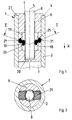
- connection end 1 and 2 show a component with at least one connection end 1, one of a Wall 2 surrounding receiving opening 3, which on an end face 4 of the component ends.
- Component e.g. from a pipe made from stable and the connection end 1 from one End of this tube.
- the tube can not in a manner known per se illustrated, the pipe end somewhat superior plastic sheathing.
- the receiving opening 3 is e.g. cylindrical and has a longitudinal axis 5 on.
- FIGS. 1 to 3 there is a device for connecting the component to another component 1 to 8 provided, one for insertion into the receiving opening 3rd certain sleeve 6 and a screwable into this, with an external thread 7th provided threaded bolt 8 contains.
- Sleeve 6 according to a first embodiment of a cylindrical sleeve, the External cross section essentially the diameter of the receiving opening 3 and its Inner diameter essentially corresponds to the diameter of the threaded bolt 8.
- the sleeve 6 is provided with at least one radial recess 18 provided in the opposite sides at least two resiliently designed, substantially parallel to the longitudinal axis 5 Leg 19.20 protrude, the ends of which face each other with a small distance.
- the exemplary embodiment is the sleeve 6 which extends through the recess 18 transversely to the longitudinal axis 5 provided, on both sides of the longitudinal axis 5 and on two diametrically opposite Place a pair of opposing legs 19, 20 protrudes.
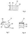
- Toothed wedges 21 are pivotally mounted, the shape of which can be seen in FIGS. 4 to 8. After that each toothed wedge has 21 end sections 22 and 23 and one arranged between them, of Both sides worked on taper or constriction 24, the concave recesses forms, in the assembly of FIGS. 1 and 2, the ends of the pairs opposite legs 19,20 are inserted so that the toothed wedges 21 in the Spaces between these can be pivoted about axes in the manner of pivot levers are stored, which are substantially perpendicular to the longitudinal axis 5.
- the toothed wedges 21 are provided on the outer sides of their end sections 22 with at least one, preferably with a plurality of first teeth 25, which serve as barbs acting opposite to the joining direction (arrow v ).
- the toothed wedges 21, on the other hand, have at least one second tooth 26, which is used for screwing in the threaded bolt 8, fits into the threads thereof and can act as an internally threaded section of the sleeve 6.
- each toothed wedge 21 is between the associated legs 19,20 arranged that the end portions 22 and first teeth 25 radially outside End sections 23 and second teeth 26, however, are located radially on the inside.
- the Arrangement made so that the maximum distance between the tips of the first and second Teeth 25,26 is slightly larger than the distance of the wall 2 from the threaded bolt 8 in assembled state corresponds, so that the teeth 25 and 26 even then something about the Sleeve 6 can protrude inwards or outwards when the toothed wedges 21 are almost radial are arranged.
- the sleeve 6 has at its axial ends a first, projecting radially outwards Stop element 27 and a second, radially inwardly projecting stop element 28.
- FIG. 3 shows, from two identical half-shells 6a and 6b, each forming a recess 18 Have recess 18a, 18b and a pair of legs projecting into this 19.20 and are separated along a separating surface which is essentially parallel to the longitudinal axis 5 runs.
- three or more shells could be used and three or more accordingly Toothed wedges 21 may be provided.
- the existing sections 18a, 18b can be hinge-like webs and possibly an adhesive tape or the like held together his.
- the device according to FIGS. 1 to 8 is used essentially as follows:
- the sleeve 6 provided with the toothed wedges 21 is inserted with the stop element 28 first into the receiving opening 3 until the stop element 27 bears against its outer end face.
- the threaded bolt 8 is then inserted into the sleeve 6 without rotating movement until it rests on the stop element 28.
- the threaded bolt 8 is moved between the second, radially inner teeth 26, which deflect resiliently in the direction of arrow v , because the toothed wedges 21 can take the resilient legs 19, 20 with them during this pivoting movement.
- the toothed wedge 21 shown on the left is pivoted clockwise in FIG.
- the threaded bolt 8 has, for example, a screw head, not shown, which can be actuated by a tool.
- a screw head not shown
- the threaded bolt 8 has, for example, a screw head, not shown, which can be actuated by a tool.
- its free end is supported on the stop element 28, while at the same time the teeth 26 enter the threads of the thread 7 of the bolt 8 and move upward in this in FIG. 1.
- the sleeve 6 out of the receiving opening 3 against the joining direction (arrow v ), ie to load it under tension.
- the barb tips of the first teeth 25, which are pressed more and more against the wall 2 of the receiving opening 3 when the threaded bolt 8 is inserted, gradually dig into the latter and thereby prevent such axial movements of the sleeve 6.
- connection end of a second component corresponding to the connection end 1 according to FIGS. 1 and 2 it would be possible to first fasten the threaded bolt 8 in a connection end of a second component corresponding to the connection end 1 according to FIGS. 1 and 2 and then to insert it only into the receiving opening 3 so far that its free end does not touch the connection element 28.
- the axial abutment required for tightening the connection is created in that the other component in FIG. 1 rests on the end face 4 or the stop element 27 from above. If the second component is then rotated, the second teeth 26 move analogously to the above description in the threads of the bolt 8 in a direction opposite to the arrow v , whereby the connection is tightened.
- connection end 1 with its Receiving opening 3 plugged onto the threaded bolt 8 and then by turning the entire component attached to this. It can either be the component with its Support the end face 4 on the wall or on the floor or the bolt 8 on the stop 28.
- the tooth wedges 21 are preferably made of a hardened steel which is harder than that Is material from which the wall 2 surrounding the receiving opening 3 is made.
- FIGS. 9 to 22 are based on the same principle of action like the embodiment of FIGS. 1 to 8 and are explained below, wherein the same parts are provided with the same reference numerals.
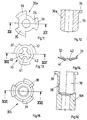
- a sleeve 30 is provided, the outer diameter of which essentially corresponds to the diameter of the receiving opening 3 and the inner diameter of which essentially corresponds to the diameter of the bolt 3.
- the sleeve 30 has in a central region at least one cut-through in the form of a radial slot 31 through which a first, radial, outwardly projecting segment 32 (FIG. 10) of a loose insert, preferably made of hardened steel, is inserted Belleville spring 33 protrudes.
- the radially outer end 32a of the segment 32 is sharp-edged and acts in a direction opposite to the joining direction (arrow w in FIG. 9) analogous to the teeth 25 (FIG. 1) as a barb.
- the plate spring 33 has three segments 32, which are arranged like a segment of a circle and are spaced apart in the circumferential direction by edge cutouts 34.
- the insert 30 has three slots 31.
- Section 30a is continuous formed as a sleeve and with three radially outwardly projecting, Provide axially parallel ribs 35, which at their upper ends in FIG. 90 ° outwardly projecting lugs 36 are provided.
- the inside diameter of the sleeve corresponds essentially to the diameter of the threaded bolt 8, during the Diameter of the cylindrical surface formed by the outer surfaces of the ribs 36 in essentially corresponds to the inside diameter of the receiving opening 3.
- Section 30b in a lower part in FIGS. 15, 16 is sleeve-shaped, being Inner diameter is essentially the outer diameter of the bolt 8 and Outer diameter essentially corresponds to the diameter of the receiving opening 3.
- the upper part of this section 30b in FIG. 16, on the other hand, is through three to a longitudinal axis 37 parallel segments 38 are formed, which run along cylinder sections and in Are circumferentially spaced by an amount that the measured in the circumferential direction Corresponds to the width of the ribs 35 of the section 30a.
- the diameter of the of the Outer surfaces of the segments 38 defined cylinder surface corresponds essentially to that Diameter of the receiving opening 3.
- the inner diameter of the of the segments 38 limited hollow cylinder corresponds to the diameter measured between the ribs 35 of the section 30a, so that this in Fig. 16 axially from above into the section 30b can be inserted, the ribs 35 in the spaces between the Segments 38 occur.
- the segments 38 point radially externally projecting lugs 39, which after the introduction of the section 30a in the Section 30b come to rest between the lugs 36 and with these a first Form the stop element.
- the second stop element can in this embodiment be designed analogously to the stop element 28 (FIG. 1).
- the plate spring 33 has three segments 32 (FIGS. 10, 13, 14), which can be inserted from above into the section 30 b in such a way that the segments 32 lie in a slot between two segments 38 and the section 30 a come.
- the plate spring 33 has a center hole 40 for the threaded bolt 8, the edge of which is delimited by three tabs 41 which are formed by cutout segments 42 in the form of circular segments in the middle part of the plate spring 33.
- the tabs 41 are preferably slightly oblique in the joining direction (arrow w in FIG. 9), while the segments 32 are slightly inclined in the opposite direction.
- the diameter of the inner circle delimited by the tabs 41 is preferably somewhat smaller than the diameter of the threaded bolt 8, while the diameter of the circle formed by the outer ends of the segments 32 is preferably somewhat larger than the diameter of the receiving opening 3.
- the sleeve 30 is appropriately preassembled by first the plate spring 33 and then section 30a is inserted into section 30b. After this assembly protrude outer ends of the segments 32 of the plate spring 33 slightly over the outer circumference of the Sections 30a, 30b radially outward and the outer ends of the tabs 41 of the plate spring 33 radially inwards somewhat beyond the inner circumference of the sections 30a, 30b.
- the bottom of section 30a and the top of the sleeve-shaped Part of section 30b may be provided with conical or stepped surfaces in such a way that in the assembled state sufficiently large to pass through the segments 32 of the plate spring 33 suitable slots 31 (Fig. 9) can be obtained.
- Sections 30a, 30b after being joined by gluing or otherwise into a fixed one To connect the unit together.
- the three segments each 32 and 38, ribs 35 and flap 41 are only examples and their shape and number can also be chosen differently.
- the device according to FIGS. 9 to 16 is used analogously to the previous example in that first the sleeve 30 is inserted into the receiving opening 3 and then the bolt 8 is inserted into the sleeve 30 without rotating movement. Both the segments 32 and the tabs 41 of the plate spring 33 can yield resiliently until the arrangement according to FIG. 9 is reached.
- the tabs 41 move upward in its threads opposite to the arrow w , as a result of which the barbed outer edges 32a of the segments 32 of the plate spring 33 dig into the wall 2 and, if necessary, delimit the lower slots 31 Put on walls.
- a tight fit of the device in the receiving opening 3 is also achieved in this embodiment.
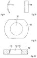
- the exemplary embodiment according to FIGS. 17 to 22 has a sleeve 44 which, analogously to FIG. 3, consists of two halves 44a, 44b (FIG. 18) which are separated along a separating surface which runs essentially parallel to the longitudinal axis 5.
- the halves 44a, 44b each have a radially outwardly projecting stop element 45 at one end and a second stop element 46 in the form of a base at the opposite end.
- a groove 47a, 47b is also formed in this bottom, which in the collapsed state of the sections 44a, 44b form a slot 47 (FIG. 17) which projects radially through the sleeve 44.
- a locking element in the form of a leaf spring 48 is inserted into the grooves 47a, 47b, the length of which is somewhat greater than the length of the grooves 47a, 47b or the slot 47, so that it protrudes somewhat laterally with its sharp-edged ends 48a which act as barbs.
- the shape of the recess or the slot 47 viewed from the stop element 45, is curved somewhat concavely, and the leaf spring 48 is correspondingly concave according to FIGS. 17, 19.
- the zones of the slot 47 adjoining the outer casing of the sleeve 44, as shown in FIGS. 17, 18, are somewhat conically widened in the axial direction.
- the ends of the leaf spring 48 can spring out in a direction opposite to the arrow x . If the sleeve 44 is then to be moved in the opposite direction of the arrow x and subjected to tension, the sharp edges of the ends 48a of the leaf spring 48 dig into the wall 3, whereby they can only deflect until they lie against the bottom of the slot 47.
- the sleeve 44 in a between the Stop elements 45,46 lying area one of recesses 49a, 49b in the Sections 44a, 44b formed cavity 49 into which one is enlarged in Fig. 21,22 shown folding nut 50 and a bias spring 51 are inserted.
- the folding nut 50 is normally arranged (Fig. 17) that the by their center hole 52 (Fig. 21,22) extending axis an angle with the longitudinal axis 5 of the Sleeve 44 forms.
- e.g. 17 has an approximately triangular shape Cross-section on, in one corner 53 (in Fig. 17 left) one side end the folding nut 50 is pivotally mounted, while a diametrically opposite one End of the folding nut 50 abuts a stop surface 54.
- Threads 55 (FIG. 22) bordering the center hole 52 are exactly coaxial in this inclined position aligned with the longitudinal axis 5 so that the threaded bolt 8 in this inclined position in the Folding nut 50 can be screwed in (Fig. 17).
- the threaded bolt 8 is to be inserted into the folding nut 50 analogously to the other exemplary embodiments without a rotary movement, it is only necessary to press it axially firmly against the latter.
- the folding nut 50 is then pivoted about the end in the corner 53 by compressing the biasing spring 51 in the direction of the arrow x , whereby the central hole 52 for the bolt 8 opens further and this can now be pushed through to the second stop element 46 without rotating movement.
- the folding nut 50 comes under the influence of the biasing spring 51 back into the position shown in FIG. 17, so that the thread of the threaded bolt 8 now engages in its threads 55 and can be rotated in this direction of rotation to the described device in the receiving opening 3rd to fix.
- the sleeve 44 according to FIGS. 17 to 22 is analogous to the others described Sleeves designed so that their outer diameter approximately the diameter of the receiving opening 3 and its inner diameter corresponds approximately to the pin diameter.
- the two sections of the sleeves 17, 30 and 44 are preferably made of plastic made by injection molding.
- the barbed parts are preferred Made of hardened steel and especially materials that are harder than that Is material from which the wall 2 of the receiving opening 3 is made. This ensures that the barbs are effective not only by clamping, but by doing so be that they penetrate into the wall material, get caught in it and only with Violence or by exerting great tensile forces and destroying the wall material the receiving opening 3 can be pulled out.
- All of the described exemplary embodiments have the advantage that they are simple and inexpensive to manufacture and easy to assemble parts and that neither to tighten the connection nor to screw the threaded bolts in for the first time the sleeves require a rotational movement of the threaded bolt. This allows the desired connections or fastenings quickly and without great assembly effort getting produced.
- the invention is not restricted to the exemplary embodiments described, which are based on can be modified in many ways. This is especially true for the shape, number and Arrangement of the different teeth and edges that act as barbs. Is further it is clear to the person skilled in the art that the devices described are analogous to EP 0 477 713 B1 also for fastening a tubular component, e.g. of a pipe, on a plate-shaped Component, e.g. can be used on a rosette. In the embodiment 9 it would be e.g.
- the sleeve 30 or its portions 30a, 30b instead of with the stop elements 36 with the sections assigned to one another on one Wall or the like attachable rosette lower part and in this Form sections of screw holes or the like for fastening screws.
- the sleeve 30 would thus be an integral part of a rosette part form.
- the devices described can also be used for connection / fastening used by other than tubular components.
Abstract
Description
Die Erfindung betrifft eine Vorrichtung der in den Oberbegriffen der Ansprüche 1 und 17
angegebenen Gattung.The invention relates to a device in the preambles of
Vorrichtungen dieser Art sind in zahlreichen Ausführungsformen bekannt. Sie dienen vor allem zur Verbindung der Bauteile von baukastenartig aus Rohr- oder Stangen- und Knotenelementen bestehenden Rohr- bzw. Stangensystemen. Aus den Elementen des Baukastens können z.B. Dekorations- oder Möbelgestelle, Messe- und Ausstellungsstände, Rahmen, Pendeltürgriffe, Griffstangen, Möbelstücke, Geländer oder Handläufe und zahlreiche andere Gebilde zusammengesetzt werden. Alternativ können die Vorrichtungen aber auch zur Verbindung anderer Bauteile verwendet werden, sofern diese mit Aufnahmeöffnungen versehene Anschlußenden aufweisen.Devices of this type are known in numerous embodiments. They serve before all to connect the components of modular pipe or rod and Existing pipe or rod systems. From the elements of the Modules can e.g. Decorative or furniture frames, trade fair and exhibition stands, Frames, swing door handles, handle bars, furniture, railings or handrails and numerous other structures are put together. Alternatively, the devices but can also be used to connect other components, provided that they have receiving openings have provided connection ends.
Zu Befestigen oder Verbinden von Bauteilen sind Vorrichtungen bekannt, die an Hülsen
oder sonstige Kupplungselemente angeformte, nach Art von Widerhaken wirkende und
zum Eingraben in die Wand der Aufnahmeöffnung bestimmte Teile aufweisen
(GB-PS 1 477 758, US-PS 3 208 409). Die mit derartigen Mitteln herstellbaren Verbindungen
sind jedoch für die oben genannten Anwendungszwecke nicht immer ausreichend
stabil. Außerdem ist die Herstellung derartiger Hülsen od. dgl., sofern sie aus
gehärtetem Stahl bestehen sollen, kompliziert und teuer.Devices for attaching or connecting components are known which are attached to sleeves
or other coupling elements formed, acting in the manner of barbs and
have certain parts for digging into the wall of the receiving opening
(GB-
Weiterhin sind Rohrverbinder in Form von Hülsen bekannt, die sowohl innen als auch außen mit radial vorstehenden, aus der Mantelfläche der Hülse herausgestanzten, widerhakenartigen Verriegelungszungen versehen sind (DE 74 17 689 U1). Derartige Hülsen dienen zur Herstellung von Steckverbindungen zwischen zwei Rohren und bieten keine Möglichkeit, die beiden zu verbindenden Rohre mit haarfeinen Stoßfugen aneinanderstoßen zu lassen oder im Bereich des Stoßes axial zu verspannen, wie dies bei den oben genannten Anwendungszwcken meistens erwünscht ist.Furthermore, pipe connectors in the form of sleeves are known, both inside and outside with radially protruding, barb-like punched out of the outer surface of the sleeve Locking tongues are provided (DE 74 17 689 U1). Such sleeves are used to make plug connections between two pipes and do not offer any Possibility of abutting the two pipes to be connected with hair-thin butt joints to let or axially brace in the area of the joint, as in the above mentioned purposes is mostly desired.
Bei einer bekannten Vorrichtung der eingangs bezeichneten Gattung, die diesen Mangel nicht aufweist (DE 26 32 696 C2), besteht die Hülse aus einer in einem Rohr- oder Knotenelement aus Kunststoff angeordneten Metalleinlage. Bei einer weiteren bekannten Vorrichtung dieser Gattung (DE 29 04 776 C2) wird eine Kunststoffhülse durch Kleben, Querstifte, warzenförmige Eindrückungen oder dergleichen in einem Rohrende befestigt. In beiden Fällen sind die Hülsen mit Innengewindeteilen zum Einschrauben eines entsprechenden Gewindebolzens versehen und fest in einer Aufnahmeöffnung des jeweiligen Bauteils befestigt.In a known device of the generic type mentioned, this deficiency does not have (DE 26 32 696 C2), the sleeve consists of a tube or Node element made of plastic arranged metal insert. Another known one Device of this type (DE 29 04 776 C2) is a plastic sleeve by gluing, Cross pins, wart-shaped indentations or the like attached in a pipe end. In both cases, the sleeves with internal thread parts for screwing in a corresponding one Threaded bolt provided and firmly in a receiving opening of the respective Attached component.
Daneben sind Vorrichtungen der eingangs bezeichneten Gattung bekannt
(DE 40 30 978 C2), bei denen die Hülse aus einem aus Kunststoff oder Metall bestehenden
Spreizteil mit einem konischen Außenmantel besteht, das zum radialen Spreizen eines
zusätzlich in die Aufnahmeöffnung eingelegten, spreizbaren Teils dient, um dieses von
innen fest gegen die Wand der Aufnahmeöffnung zu pressen und dadurch im Bauteil durch
Klemmwirkung zu befestigen.In addition, devices of the type described at the outset are known
(
Vorrichtungen dieser Art dienen überwiegend zur Verbindung von zwei rohrförmigen Bauteilen. Sie können aber auch z.B. zur Befestigung eines Rohrelements oder dergleichen an einer Rosette oder dergleichen dienen. Dabei ist z.B. das spreizbare Teil der zuletzt genannten Vorrichtung fest mit der Rosette verbunden und mittels einer von deren Rückseite her eingeführten Schraube in der Aufnahmeöffnung eines Rohrelement oder dergleichen durch Klemmwirkung festlegbar (EP 0 477 713 B1).Devices of this type are mainly used to connect two tubular Components. But you can also e.g. for fastening a tubular element or the like serve on a rosette or the like. Here is e.g. the most expandable part of the last said device firmly connected to the rosette and by means of one of the Back inserted screw in the opening of a tubular element or The like can be determined by clamping action (EP 0 477 713 B1).
Ein Problem der zuletzt beschriebenen Vorrichtungen besteht darin, daß sie konstruktiv vergleichsweise aufwendig und dadurch teuer sind. Sie stellen wegen der Vielzahl der Vorrichtungen, die zur Herstellung eines Gestells, Geländers, Handlaufs oder dergleichen benötigt werden, einen beträchtlichen Kostenfaktor dar.A problem with the devices described last is that they are constructive are comparatively complex and therefore expensive. They pose because of the multitude of Devices used to manufacture a frame, railing, handrail or the like are a significant cost factor.
Ein weiteres Problem dieser Vorrichtungen besteht darin, daß die Gewindebolzen eine vergleichsweise große Länge besitzen und vergleichsweise tief in die Hülsen eingeschraubt werden müssen. Das Eindrehen und Festziehen der Bolzen bis zum Erreichen der gewünschten Montagestellung muß daher mit einer Vielzahl von Umdrehungen erfolgen, was die Montagezeit erhöht und insbesondere dann unerwünscht ist, wenn die Montage nicht im Werk, sondern an einer Baustelle erfolgen soll.Another problem with these devices is that the threaded bolts are one have a comparatively large length and are screwed comparatively deep into the sleeves Need to become. Screwing in and tightening the bolts until they reach the desired mounting position must therefore be carried out with a large number of revolutions, which increases the assembly time and is particularly undesirable when the assembly not at the factory, but at a construction site.
Vor diesem Hintergrund liegt der Erfindung die Aufgabe zugrunde, die Vorrichtung der eingangs bezeichneten Gattung so auszubilden, daß wenigstens eines der beiden Probleme gelöst und eine Vorrichtung erhalten wird, die einfacher hergestellt und/oder montiert werden kann.Against this background, the invention has for its object the device of the genre described at the outset so that at least one of the two problems solved and obtained a device that is easier to manufacture and / or assemble can be.
Zur Lösung dieser Aufgabe dienen die kennzeichnenden Merkmale der Ansprüche 1
und 17.The characteristic features of
Die Erfindung bringt den Vorteil mit sich, daß einerseits zur Herstellung der Vorrichtung einfache, preisgünstige Bauelemente verwendet werden können, andererseits die Festlegung der Hülse in der Aufnahmeöffnung mit wenigen Umdrehungen des Gewindebolzens erreicht wird.The invention has the advantage that, on the one hand, for the manufacture of the device simple, inexpensive components can be used, on the other hand, the definition the sleeve in the receiving opening with a few turns of the threaded bolt is achieved.
Weitere vorteilhafte Merkmale der Erfindung ergeben sich aus den Unteransprüchen.Further advantageous features of the invention emerge from the subclaims.
Die Erfindung wird nachfolgend in Verbindung mit den beiliegenden Zeichnungen an
Ausführungsbeispielen näher erläutert. Es zeigen:
Fig. 1 und 2 zeigen ein Bauteil mit wenigstens einem Anschlußende 1, das eine von einer
Wand 2 umgebene Aufnahmeöffnung 3 aufweist, die an einer Stirnseite 4 des Bauteils
endet. Bei Anwendung der Erfindung auf übliche Rohr- oder Stangensysteme besteht das
Bauteil z.B. aus einem aus Stall hergestellten Rohr und das Anschlußende 1 aus einem
Ende dieses Rohrs. Das Rohr kann dabei in an sich bekannter Weise mit einer nicht
dargestellten, das Rohrende etwas überragenden Kunststoffummantelung versehen sein.
Die Aufnahmeöffnung 3 ist in diesem Fall z.B. zylindrisch und weist eine Längsachse 5
auf.1 and 2 show a component with at least one
Zur Verbindung des Bauteils mit einem anderen Bauteil ist erfindungsgemäß eine Vorrichtung
nach Fig. 1 bis 8 vorgesehen, die eine zum Einsetzen in die Aufnahmeöffnung 3
bestimmte Hülse 6 und einen in diese einschraubbaren, mit einem Außengewinde 7
versehenen Gewindebolzen 8 enthält. Wie insbesondere Fig. 1 bis 3 zeigen, besteht die
Hülse 6 nach einem ersten Ausführungsbeispiel aus einer zylindrischen Hülse, deren
Außenquerschnitt im wesentlichen dem Durchmesser der Aufnahmeöffnung 3 und deren
Innendurchmesser im wesentlichen dem Durchmesser des Gewindebolzens 8 entspricht.
In einem mittleren Bereich ist die Hülse 6 mit wenigstens einer ihren Mantel durchsetzenden,
radialen Ausparung 18 versehen, in die von gegenüberliegenden Seiten her
wenigstens zwei federnd ausgebildete, zur Längsachse 5 im wesentlichen parallele
Schenkel 19,20 ragen, deren Enden sich mit geringen Abstand gegenüberstehen. Im
Ausführungsbeispiel ist die Hülse 6 quer zur Längsachse 5 durchragende Ausparung 18
vorgesehen, in die beidseitig der Längsachse 5 und an zwei diametral gegenüberliegenden
Stellen je ein Paar von sich gegenüberstehenden Schenkeln 19,20 ragt.According to the invention there is a device for connecting the component to another
In den Zwischenräumen zwischen den Schenkeln 19,20 sind nach Fig. 1 und 2 Verriegelungselemente
in Form von starren, lose zwischen die Schenkel 19,20 eingesetzten
Zahnkeilen 21 schwenkbar gelagert, deren Form aus Fig. 4 bis 8 ersichtlich ist. Danach
hat jeder Zahnkeil 21 Endabschnitte 22 und 23 und eine zwischen diesen angeordnete, von
beiden Seiten her angearbeitete Verjüngung bzw. Einschnürung 24, die konkave Ausnehmungen
bildet, in die bei der Montage nach Fig. 1 und 2 die Enden der paarweise
gegenüberliegenden Schenkel 19,20 so eingelegt werden, daß die Zahnkeile 21 in den
Zwischenräumen zwischen diesen nach Art von Schwenkhebeln um Achsen schwenkbar
gelagert sind, die im wesentlichen senkrecht zur Längsachse 5 stehen. In the spaces between the
Die Zahnkeile 21 sind an den Außenseiten ihrer Endabschnitte 22 mit wenigstens einem,
vorzugsweise mit mehreren ersten Zähnen 25 versehen, die als entgegengesetzt zur
Fügerichtung (Pfeil v) wirkende Widerhaken dienen. An den Außenseiten der Endabschnitte
23 weisen die Zahnkeile 21 dagegen wenigstens einen zweiten Zahn 26 auf, der
zum Eindrehen des Gewindebolzens 8 dient, in dessen Gewindegänge paßt und als
Innengewindeabschnitt der Hülse 6 wirken kann.The
Im montierten Zustand ist jeder Zahnkeil 21 so zwischen den zugehörigen Schenkeln
19,20 angeordnet, daß die Endabschnitte 22 und ersten Zähne 25 radial außen, die
Endabschnitte 23 und zweiten Zähne 26 dagegen radial innen liegen. Dabei ist die
Anordnung so getroffen, daß der maximale Abstand der Spitzen der ersten und zweiten
Zähne 25,26 etwas größer ist, als dem Abstand der Wand 2 vom Gewindebolzen 8 im
montierten Zustand entspricht, so daß die Zähne 25 und 26 selbst dann etwas über die
Hülse 6 nach innen bzw. außen vorstehen können, wenn die Zahnkeile 21 nahezu radial
angeordnet sind.In the assembled state, each
Die Hülse 6 weist an ihren axialen Enden je ein erstes, radial nach außen ragendes
Anschlagelement 27 und ein zweites, radial nach innen ragendes Anschlagelement 28 auf.The
Nach einer bevorzugten Ausführungsform der Erfindung besteht die Hülse 6, wie Fig. 3
zeigt, aus zwei identischen Halbschalen 6a und 6b, die je eine die Ausparrung 18 bildende
Ausparung 18a, 18b und ein Paar von in diese ragende Schenkel 19,20 aufweisen und
längs einer Trennfläche getrennt sind, die im wesentlichen parallel zur Längsachse 5
verläuft. Alternativ könnten drei oder mehr Schalen und entsprechend drei oder mehr
Zahnkeile 21 vorgesehen sein. Die vorhandenen Abschnitte 18a, 18b können durch dünne,
scharnierartige Stege und gegebenenfalls ein Klebeband oder dergleichen zusammengehalten
sein.According to a preferred embodiment of the invention, there is the
Die Vorrichtung nach Fig. 1 bis 8 wird im wesentlichen wie folgt angewendet:
Die mit den Zahnkeilen 21 versehene Hülse 6 wird mit dem Anschlagelement 28 voran in
die Aufnahmeöffnung 3 eingeführt, bis das Anschlagelement 27 an dessen äußerer
Stirnseite anliegt. Anschließend wird der Gewindebolzen 8 ohne Drehbewegung in die
Hülse 6 gesteckt, bis er am Anschlagelement 28 anliegt. Der Gewindebolzen 8 wird dabei
zwischen den zweiten, radial innen liegenden Zähnen 26 durchbewegt, die in Richtung des
Pfeils v federnd ausweichen, weil die Zahnkeile 21 bei dieser Schwenkbewegung die
federnd ausgebildeten Schenkel 19,20 mitnehmen können. So wird z.B. in Fig. 1 der links
dargestellte Zahnkeil 21 im Uhrzeigersinn verschwenkt, wobei das untere Ende des
Schenkels 19 radial nach innen und das obere Ende des Schenkels 20 radial nach außen
gedrückt wird. Nach der Einführung des Gewindebolzens 8 schwenken die Schenkel 19,20
die Zahnkeile 21 in die aus Fig. 1 und 2 ersichtliche Stellung zurück, wodurch die ersten
Zähne 25 an die Wand 2 gelegt werden, während die zweiten Zähne 26 in die Gewindegänge
des Gewindebolzens 8 eintreten. Abschließend wird der Gewindebolzen 8 in
Festdrehrichtung angezogen, wodurch die starren, vorzugsweise aus gehärtetem Stahl
bestehenden Zahnkeile 21 noch stärker verschwenkt werden und sich die ersten Zähne 25
nach Art von Widerhaken in die Wand 2 eingraben. Durch entsprechende Bemessung der
verschiedenen Teile kann erreicht werden, daß bereits mit sehr wenigen, z. B. zwei oder
drei Umdrehungen des Gewindebolzens 8 ein fester Sitz der Hülse 6 im Anschlußende 1
erreicht wird und die Zahnkeile 21 in Fig. 1 maximal etwa eine horizontale Lage quer zur
Längsachse 5 einnehmen können, wenn der Gewindebolzen 8 festgezogen ist.The device according to FIGS. 1 to 8 is used essentially as follows: The
Der Gewindebolzen 8 weist beispielsweise einen nicht gezeigten, mittels eines Werkzeugs
betätigbaren Schraubenkopf auf. Bei der Drehbewegung in Festdrehrichtung stützt sich
sein freies Ende am Anschlagelement 28 ab, während gleichzeitig die Zähne 26 in die
Gewindegänge des Gewindes 7 des Bolzens 8 eintreten und in diesen in Fig. 1 nach oben
wandern. Hierdurch besteht das Bestreben, die Hülse 6 entgegen der Fügerichtung (Pfeil
v) aus der Aufnahmeöffnung 3 herauszuziehen, d. h. auf Zug zu belasten. Das hat aber
zur Folge, daß sich die Widerhakenspitzen der ersten Zähne 25, die beim Einführen des
Gewindebolzens 8 immer stärker an die Wand 2 der Aufnahmeöffnung 3 gedrückt werden,
allmählich in diese eingraben und dadurch derartige axiale Bewegungen der Hülse 6
verhindern. Durch geeignete Dimensionierung der verschiedenen Teile kann erreicht
wreden, daß ein Lösen der auf diese Weise hergestellten Verbindung entgegengesetzt und
zum Pfeil v ohne vorheriges Losdrehen des Gewindebolzens 8 nicht mehr möglich ist.The threaded
Alternativ wäre es möglich, den Gewindebolzen 8 zunächst in einem dem Anschlußende 1
nach Fig. 1 und 2 entsprechenden Anschlußende eines zweiten Bauteils zu befestigen und
dann nur so weit in die Aufnahmeöffnung 3 einzufügen, daß sein freies Ende das Anschlußelement
28 nicht berührt. In diesem Fall wird das zum Festziehen der Verbindung
benötigte axiale Widerlager dadurch geschaffen, daß sich das andere Bauteil in Fig. 1 von
oben her auf die Stirnseite 4 bzw. das Anschlagelement 27 auflegt. Wird das zweite
Bauteil dann gedreht, wandern die zweiten Zähne 26 analog zur obigen Beschreibung in
den Gewindegängen des Bolzens 8 in einer zum Pfeil v entgegengesetzten Richtung,
wodurch die Verbindung festgezogen wird.Alternatively, it would be possible to first fasten the threaded
In analoger Weise kann schließlich vorgegangen werden, wenn der Bolzen 8 undrehbar
z. B. von einer Wand oder vom Boden od. dgl. absteht und dazu dient, das Bauteil an der
Wand oder am Boden zu befestigen. In diesem Fall wird das Anschlußende 1 mit seiner
Aufnahmeöffnung 3 auf den Gewindebolzen 8 aufgesteckt und dann durch Drehen des
gesamten Bauteils auf diesem befestigt. Dabei kann sich entweder das Bauteil mit seiner
Stirnfläche 4 an der Wand bzw. am Boden oder der Bolzen 8 am Anschlag 28 abstützen.Finally, an analogous procedure can be used if the
Die Zahnkeile 21 bestehen vorzugsweise aus einem gehärteten Stahl, der härter als das
Material ist, aus dem die die Aufnahmeöffnung 3 umgebende Wand 2 hergestellt ist.The
Die Ausführungsbeispiele nach den Fig. 9 bis 22 beruhen auf demselben Wirkungsprinzip wie das Ausführungsbeispiel nach Fig. 1 bis 8 und werden nachfolgend erläutert, wobei gleiche Teile mit denselben Bezugszeichen versehen werden.The exemplary embodiments according to FIGS. 9 to 22 are based on the same principle of action like the embodiment of FIGS. 1 to 8 and are explained below, wherein the same parts are provided with the same reference numerals.
Beim Ausführungsbeispiel nach Fig. 9 bis 16 ist eine Hülse 30 vorgesehen, deren
Außendurchmesser im wesentlichen dem Durchmesser der Aufnahmeöffnung 3 und deren
Innendurchmesser im wesentlichen dem Durchmesser des Bolzens 3 entspricht. Die Hülse
30 weist in einem mittleren Bereich wenigstens eine, ihren Mantel durchsetzende,Aussparung
in Form eines radialen Schlitzes 31 auf, durch den ein erstes, radiales, nach
außen ragendes Segment 32 (Fig. 10) einer vorzugsweise aus gehärtetem Stahl bestehenden,
lose eingesetzten Tellerfeder 33 ragt. Das radial äußere Ende 32a des Segments 32 ist
scharfkantig ausgebildet und wirkt in einer zur Fügerichtung (Pfeil w in Fig. 9) entgegengesetzten
Richtung analog zu den Zähnen 25 (Fig. 1) als Widerhaken. Im Ausführungsbeispiel
(Fig. 10) weist die Tellerfeder 33 drei Segmente 32 auf, die kreissegmentartig
angeordnet und in Umfangsrichtung durch Randausschnitte 34 beabstandet sind.
Entsprechend weist das Einlegeteil 30 drei Schlitze 31 auf.In the exemplary embodiment according to FIGS. 9 to 16, a
Zur Vereinfachung der Herstellung besteht das Einlegeteil 30 nach Fig. 11 und 12 bzw.
15 und 16 vorzugsweise aus zwei die Schlitze 31 bildenden Abschnitten 30a und 30b, die
längs einer im wesentlichen senkrecht zur Längsachse 5 verlaufenden Fläche getrennt sind
und zwischen denen die Tellerfeder 33 zu liegen kommt. Der Abschnitt 30a ist durchgehend
als Hülse ausgebildet und am Umfang mit drei radial nach außen ragenden,
achsparallelen Rippen 35 versehen, die an ihren in Fig. 11,12 oberen Enden mit um ca.
90° nach außen ragenden Ansätzen 36 versehen sind. Der Innendurchmesser der Hülse
entspricht im wesentlichen dem Durchmesser des Gewindebolzens 8, während der
Durchmesser der von den Außenflächen der Rippen 36 gebildeten Zylinderfläche im
wesentlichen dem Innendurchmesser der Aufnahmeöffnung 3 entspricht. Dagegen ist der
Abschnitt 30b in einem in Fig. 15,16 unteren Teil hülsenförmig ausgebildet, wobei sein
Innendurchmesser im wesentlichen dem Außendurchmesser des Bolzens 8 und sein
Außendurchmesser im wesentlichen dem Durchmesser der Aufnahmeöffnung 3 entspricht.
Das in Fig. 16 obere Teil dieses Abschnitts 30b ist dagegen durch drei zu einer Längsachse
37 parallele Segmente 38 gebildet, die längs Zylinderabschnitten verlaufen und in
Umfangsrichtung um ein Maß beabstandet sind, das der in Umfangsrichtung gemessenen
Breite der Rippen 35 des Abschnitts 30a entspricht. Der Durchmesser der von den
Außenflächen der Segmente 38 definierten Zylinderfläche entspricht im wesentlichen dem
Durchmesser der Aufnahmeöffnung 3. Der Innendurchmesser des von den Segmenten 38
begrenzten Hohlzylinders entspricht dem zwischen den Rippen 35 gemessenen Durchmesser
des Abschnitts 30a, so daß dieser in Fig. 16 von oben her axial in den Abschnitt
30b eingeführt werden kann, wobei die Rippen 35 in die Freiräume zwischen den
Segmenten 38 treten. An den in Fig. 16 oberen Enden weisen die Segmente 38 radial nach
außen ragende Ansätze 39 auf, die nach dem Einführen des Abschnitts 30a in den
Abschnitt 30b zwischen den Ansätzen 36 zu liegen kommen und mit diesen ein erstes
Anschlagelement bilden. Das zweite Anschlagelement kann bei dieser Ausführungsform
analog zum Anschlagelement 28 (Fig. 1) ausgebildet sein.To simplify production, there is an
Die Tellerfeder 33 weist im Ausführungsbeispiel drei Segmente 32 auf (Fig. 10,13,14),
die von oben her so in den Abschnitt 30b eingeführt werden können, das die Segmente 32
in einem Schlitz zwischen je zwei Segmenten 38 und dem Abschnitt 30a zuliegen kommen.
In ihrem Zentrum weist die Tellerfeder 33 ein Mittelloch 40 für den Gewindebolzen
8 auf, dessen Rand durch drei Lappen 41 begrenzt ist, die durch im Mittelteil der
Tellerfeder 33 angebracht, kreissegmentförmige Ausschnitte 42 gebildet sind. Wie
insbesondere Fig. 9 und 14 zeigen, sind vorzugsweise die Lappen 41 leicht schräg in
Fügerichtung (Pfeil w in Fig. 9), die Segmente 32 dagegen leicht in der dazu entgegengesetzten
Richtung geneigt. Außerdem ist der Durchmesser des von den Lappen 41
begrenzten Innenkreises vorzugsweise etwas kleiner als der Durchmesser des Gewindebolzens
8, der Durchmesser des von den äußeren Enden der Segmente 32 gebildeten Kreises
dagegen vorzugsweise etwas größer als der Durchmesser der Aufnahmeöffnung 3.In the exemplary embodiment, the
Die Hülse 30 wird zweckmäßig vormontiert, indem zunächst die Tellerfeder 33 und dann
der Abschnitt 30a in den Abschnitt 30b eingelegt wird. Nach dieser Montage ragen die
äußeren Enden der Segmente 32 der Tellerfeder 33 etwas über den Außenumfang der
Abschnitte 30a,30b radial nach außen und die äußeren Enden der Lappen 41 der Tellerfeder
33 etwas über den Innenumfang der Abschnitte 30a,30b hinaus radial nach innen.
Dabei können die Unterseite des Abschnitts 30a und die Oberseite des hülsenförmigen
Teils des Abschnitts 30b derart mit konischen oder abgestuften Flächen versehen sein, das
im montierten Zustand ausreichend große, zum Durchtritt der Segmente 32 der Tellerfeder
33 geeignete Schlitze 31 (Fig. 9) erhalten werden. Außerdem wäre es möglich, die
Abschnitte 30a,30b nach dem Zusammenfügen durch Kleben oder sonstwie zu einer festen
Baueinheit miteinander zu verbinden. Schließlich ist klar, daß die jeweils drei Segmente
32 und 38, Rippen 35 und Lappen 41 nur Beispiele darstellen und deren Form und Anzahl
auch anders gewählt sein kann.The
Die Anwendung der Vorrichtung nach Fig. 9 bis 16 erfolgt analog zum vorhergehenden
Beispiel dadurch, daß zunächst die Hülse 30 in die Aufnahmeöffnung 3 und dann der
Bolzen 8 ohne Drehbewegung in die Hülse 30 gesteckt wird. Dabei können sowohl die
Segmente 32 als auch die Lappen 41 der Tellerfeder 33 federnd nachgeben, bis die
Anordnung nach Fig. 9 erreicht ist. Beim nachfolgenden Festziehen des Gewindebolzens 8
wandern die Lappen 41 in dessen Gewindegängen entgegengesetzt zum Pfeil w nach oben,
wodurch sich gleichzeitig die widerhakenartig wirkenden Außenkanten 32a der Segmente
32 der Tellerfeder 33 in die Wand 2 eingraben und ggf. auf die unteren, die Schlitze 31
begrenzenden Wandungen auflegen. Mit nur wenigen Umdrehungen des Gewindebolzens 8
wird auch bei diesem Ausführungsbeispiel ein fester Sitz der Vorrichtung in der Aufnahmeöffnung
3 bewirkt.The device according to FIGS. 9 to 16 is used analogously to the previous example in that first the
Das Ausführungsbeispiel nach Fig. 17 bis 22 weist eine Hülse 44 auf, die analog zur
Fig. 3 aus zwei Hälften 44a,44b (Fig. 18) besteht, die längs einer im wesentlichen parallel
zur Längsachse 5 verlaufenden Trennfläche getrennt sind. Die Hälften 44a,44b weisen am
einen Ende jeweils ein radial nach außen ragendes Anschlagelement 45 und am entgegengesetzten
Ende ein zweites Anschlagelement 46 in Form eines Bodens auf. In diesem
Boden ist außerdem je eine Nut 47a,47b ausgebildet, die im zusammengelegten Zustand
der Abschnitte 44a,44b einen die Hülse 44 radial durchragenden Schlitz 47 (Fig. 17)
bilden. In die Nuten 47a,47b wird vor dem Verbinden der Abschnitte 44a,44b ein
Verriegelungselement in Form einer vorzugsweise aus gehärtetem Stahl bestehende
Blattfeder 48 eingelegt, deren Länge etwas größer ist, als der Länge der Nuten 47a,47b
bzw. des Schlitzes 47 entspricht, so daß sie mit ihren scharfkantigen, als Widerhaken
wirksamen Enden 48a etwas seitlich aus diesen herausragt. Die Form der Aussparung
bzw. des Schlitzes 47 ist, vom Anschlagelement 45 her betrachtet, etwas konkav gewölbt,
und die Blattfeder 48 ist gemäß Fig. 17, 19 entsprechend konkav geformt. Außerdem sind
die an dem Außenmantel der Hülse 44 grenzenden Zonen des Schlitzes 47, wie Fig. 17,
18 zeigen, in axialer Richtung etwas konisch aufgeweitet. Wird daher die aus den
Abschnitten 44a,44b und der Blattfeder 48 bestehende, vormontierte Hülse 44 in Fügerichtung
(Pfeil x in Fig. 17) in die Aufnahmeöffnung 3 eingeschoben, können die Enden der
Blattfeder 48 in einer zum Pfeil x entgegengesetzten Richtung federnd ausweichen. Soll
danach die Hülse 44 entgegen dem Pfeil x bewegt und auf Zug beansprucht werden,
graben sich die scharfen Kanten der Enden 48a der Blattfeder 48 in die Wand 3 ein,
wobei sie höchstens soweit ausweichen können, bis sie am Boden des Schlitzes 47
anliegen.The exemplary embodiment according to FIGS. 17 to 22 has a
Im Gegensatz zu den beiden bisher beschriebenen Ausführungsbeispielen werden beim
Ausführungsbeispiel der Fig. 17 bis 22 die Funktionen der Widerhaken einerseits und des
vereinfachten Einsteckens des Gewindebolzens 8 andererseits nicht mit denselben Elementen
(z. B. 21,33 in Fig. 1 und 9), sondern mit voneinander unabhängigen, unterschiedlichen
Elementen der Hülse 44 realisiert. Hierzu weist die Hülse 44 in einem zwischen den
Anschlagelementen 45,46 liegenden Bereich einen von Aussparungen 49a,49b in den
Abschnitten 44a,44b gebildeten Hohlraum 49 auf, in den eine in Fig. 21,22 vergrößert
dargestellte Klappmutter 50 und eine Vorspannfeder 51 eingelegt werden. Dabei wird
durch eine entsprechende Formgebung des Hohlraums 49 und der Vorspannfeder 51 dafür
gesorgt, daß die Klappmutter 50 normalerweise so angeordnet ist (Fig. 17), daß die durch
ihr Mittelloch 52 (Fig. 21,22) verlaufende Achse einen Winkel mit der Längsachse 5 der
Hülse 44 bildet. Hierzu weist z.B. der Hohlraum 49 gemäß Fig. 17 einen etwa dreieckförmigen
Querschnitt auf, in dessen einer Ecke 53 (in Fig. 17 links) das eine seitliche Ende
der Klappmutter 50 schwenkbar gelagert ist, während ein diametral gegenüberliegendes
Ende der Klappmutter 50 an einer Anschlagfläche 54 anliegt. Außerdem sind die an das
Mittelloch 52 grenzenden Gewindegänge 55 (Fig. 22) in dieser Schräglage genau koaxial
zur Längsachse 5 ausgerichtet, so daß der Gewindebolzen 8 in dieser Schräglage in die
Klappmutter 50 eingeschraubt werden kann (Fig. 17).In contrast to the two exemplary embodiments described so far, the
Embodiment of FIGS. 17 to 22, the functions of the barb on the one hand and the
simplified insertion of the threaded
Soll der Gewindebolzen 8 analog zu den anderen Ausführungsbeispielen ohne Drehbewegung
in die Klappmutter 50 eingeführt werden, ist es lediglich erforderlich, ihn axial fest
gegen diese zu drücken. Die Klappmutter 50 wird dann um das in der Ecke 53 liegende
Ende unter Zusammendrücken der Vorspannfeder 51 in Richtung des Pfeils x verschwenkt,
wodurch sich das Mittelloch 52 für den Bolzen 8 weiter öffnet und dieser jetzt
ohne Drehbewegung bis zum zweiten Anschlagelement 46 durchgeschoben werden kann.
Danach gelangt die Klappmutter 50 unter dem Einfluß der Vorspannfeder 51 wieder in die
aus Fig. 17 ersichtliche Position, so daß das Gewinde des Gewindebolzens 8 jetzt in deren
Gewindegänge 55 eingreift und in dieser Festdrehrichtung gedreht werden kann, um die
beschriebene Vorrichtung in der Aufnahmeöffnung 3 zu fixieren.If the threaded
Im übrigen ist die Hülse 44 nach Fig. 17 bis 22 analog zu den anderen beschriebenen
Hülsen so ausgebildet, daß ihr Außendurchmesser etwa dem Durchmesser der Aufnahmeöffnung
3 und sein Innendurchmesser etwa dem Bolzendurchmesser entspricht.Otherwise, the
Die beiden Abschnitte der Hülsen 17, 30 und 44 werden vorzugsweise aus Kunststoff
durch Spritzguß hergestellt. Dagegen werden die Widerhaken aufweisenden Teile vorzugsweise
aus gehärtetern Stahl und insbesondere aus Materialien hergestellt, die härter als das
Material ist, aus dem die Wand 2 der Aufnahmeöffnung 3 besteht. Dadurch wird sichergestellt,
daß die Widerhaken nicht allein durch Klemmung, sondern dadurch wirksam
werden, daß sie in das Wandmaterial eindringen, sich in diesem verhaken und nur mit
Gewalt bzw. durch Ausübung großer Zugkräfte und Zerstörung des Wandmaterials aus
der Aufnahmeöffnung 3 herausgezogen werden können.The two sections of the
Alle beschriebenen Ausführungsbeispiele bringen den Vorteil mit sich, daß sie aus einfach und preisgünstig herstellbaren und leicht fügbaren Teilen zusammengesetzt sind und das weder zum Festziehen der Verbindung noch zum ersten Eindrehen der Gewindebolzen in die Hülsen eine Drehbewegung der Gewindebolzen erforderlich ist. Dadurch können die gewünschten Verbindungen bzw. Befestigungen schnell und ohne großen Montageaufwand hergestellt werden.All of the described exemplary embodiments have the advantage that they are simple and inexpensive to manufacture and easy to assemble parts and that neither to tighten the connection nor to screw the threaded bolts in for the first time the sleeves require a rotational movement of the threaded bolt. This allows the desired connections or fastenings quickly and without great assembly effort getting produced.
Die Erfindung ist nicht auf die beschriebenen Ausführungsbeispiele beschränkt, die auf
vielfache Weise abgewandelt werden können. Dies gilt vor allem für die Form, Zahl und
Anordnung der verschiedenen, als Widerhaken wirksamen Zähne und Kanten. Weiter ist
für den Fachmann klar, daß die beschriebenen Vorrichtungen analog zu EP 0 477 713 B1
auch zur Befestigung eines rohrförmigen Bauteils, z.B. eines Rohrs, an einem plattenförmigen
Bauteil, z.B. an einer Rosette verwendet werden können. Bei der Ausführungsform
nach Fig. 9 wäre es z.B. möglich, die Hülse 30 bzw. deren Abschnitte 30a,30b anstatt mit
den Anschlagelementen 36 mit den aneinander zugeordneten Abschnitten eines an einer
Wand oder dergleichen befestigbaren Rosettenunterteils zu versehen und in diesen
Abschnitten Schraublöcher oder dergleichen für Befestigungsschrauben auszubilden. In
diesem Fall würde die Hülse 30 somit einen integralen Bestandteil eines Rosettemmterteils
bilden. Außerdem können die beschriebenen Vorrichtungen auch zur Verbindung/Befestigung
von anderen als rohrförmigen Bauteilen verwendet werden. Schließlich versteht sich,
daß die einzelnen Merkmale auch in anderen als den dargestellten und beschriebenen
Kombinationen angewendet werden können.The invention is not restricted to the exemplary embodiments described, which are based on
can be modified in many ways. This is especially true for the shape, number and
Arrangement of the different teeth and edges that act as barbs. Is further
it is clear to the person skilled in the art that the devices described are analogous to EP 0 477 713 B1
also for fastening a tubular component, e.g. of a pipe, on a plate-shaped
Component, e.g. can be used on a rosette. In the embodiment
9 it would be e.g. possible, the
Claims (18)
Applications Claiming Priority (2)
| Application Number | Priority Date | Filing Date | Title |
|---|---|---|---|
| DE19949695 | 1999-10-15 | ||
| DE1999149695 DE19949695A1 (en) | 1999-10-15 | 1999-10-15 | Device for fastening or connecting components |
Publications (2)
| Publication Number | Publication Date |
|---|---|
| EP1092881A2 true EP1092881A2 (en) | 2001-04-18 |
| EP1092881A3 EP1092881A3 (en) | 2002-06-12 |
Family
ID=7925731
Family Applications (1)
| Application Number | Title | Priority Date | Filing Date |
|---|---|---|---|
| EP00122516A Withdrawn EP1092881A3 (en) | 1999-10-15 | 2000-10-14 | Device for fastening or connecting structural members |
Country Status (2)
| Country | Link |
|---|---|
| EP (1) | EP1092881A3 (en) |
| DE (1) | DE19949695A1 (en) |
Cited By (4)
| Publication number | Priority date | Publication date | Assignee | Title |
|---|---|---|---|---|
| KR20040009094A (en) * | 2002-07-22 | 2004-01-31 | 이시재 | Fixing device |
| EP1388451A1 (en) * | 2002-08-08 | 2004-02-11 | Dr.Ing. h.c.F. Porsche Aktiengesellschaft | Oil filler cap for combustion engine |
| WO2004106767A2 (en) * | 2003-05-26 | 2004-12-09 | Christian Bauer Gmbh + Co. | Plate spring, which is prevented from being axially displaced on a circular cylindrical surface of a receiving body |
| CN105736535A (en) * | 2016-04-20 | 2016-07-06 | 龚海常 | Telescopic mechanism for furniture |
Families Citing this family (4)
| Publication number | Priority date | Publication date | Assignee | Title |
|---|---|---|---|---|
| DE102005027281B4 (en) * | 2005-06-14 | 2007-03-15 | Itw Automotive Products Gmbh & Co. Kg | Connecting device between an elongated member and a threaded rod |
| DE102015202593A1 (en) | 2015-02-12 | 2016-08-18 | Lamello Ag | Dowel element, fastening device, method for producing a dowel element and method for mounting a fastening device |
| DE102016215512A1 (en) * | 2016-08-18 | 2018-02-22 | Volkswagen Aktiengesellschaft | Mounting arrangement between two components |
| DE102019124390A1 (en) * | 2019-09-11 | 2021-03-11 | Schmitz Cargobull Aktiengesellschaft | Door locking device and commercial vehicle body with door locking device |
Citations (7)
| Publication number | Priority date | Publication date | Assignee | Title |
|---|---|---|---|---|
| US3208409A (en) | 1964-05-25 | 1965-09-28 | John Gale Company | Desk device |
| DE7417689U (en) | 1975-02-27 | Deutsche Tecalemit Gmbh | Tube with non-detachable plug connection | |
| GB1477758A (en) | 1974-06-12 | 1977-06-29 | Illinois Tool Works | Screw anchor clips |
| DE2632696A1 (en) | 1976-07-21 | 1978-01-26 | Wilke | Tubular structure assembly system - has tapped coupling ends in tubular and nodal components for screw connections |
| DE2904776C2 (en) | 1979-02-08 | 1993-03-04 | Heinrich Wilke Gmbh, 3548 Arolsen, De | |
| EP0477713B1 (en) | 1990-09-27 | 1994-05-04 | HEWI Heinrich Wilke GmbH | Device for fastening a tubular member to a wall or the like |
| DE4030978C2 (en) | 1990-09-27 | 1996-12-12 | Wilke Heinrich Hewi Gmbh | Connection device for pipes |
Family Cites Families (11)
| Publication number | Priority date | Publication date | Assignee | Title |
|---|---|---|---|---|
| DE117017C (en) * | 1899-11-04 | |||
| FR912009A (en) * | 1944-01-24 | 1946-07-26 | Nut and screw connection | |
| US2528675A (en) * | 1947-01-20 | 1950-11-07 | Tinnerman Products Inc | Fastening device |
| CH281695A (en) * | 1950-05-25 | 1952-03-31 | Egli Willy | Metal expansion anchor. |
| FR1111686A (en) * | 1954-09-22 | 1956-03-02 | Ankle | |
| DE1918869U (en) * | 1964-12-01 | 1965-07-01 | Artur Fischer | DOWELS FOR FIXING OBJECTS IN BUILDING MATERIAL |
| FR2217580B1 (en) * | 1973-02-10 | 1978-06-02 | Molyneux Godfrey | |
| DE3201365A1 (en) * | 1981-10-06 | 1983-04-14 | Beckmann KG, 7410 Reutlingen | Device for preventing axial movement of a guided round-profiled body, especially of a tap tube in a beer keg |
| DE8323284U1 (en) * | 1983-08-12 | 1984-01-12 | Ehlert, Marianne | Sheet metal dowels |
| US5242252A (en) * | 1990-02-09 | 1993-09-07 | Haerle Anton | Self-locking threaded connection |
| GB9209155D0 (en) * | 1992-04-28 | 1992-06-10 | Dzus Fastener Europe | A fastening device |
-
1999
- 1999-10-15 DE DE1999149695 patent/DE19949695A1/en not_active Withdrawn
-
2000
- 2000-10-14 EP EP00122516A patent/EP1092881A3/en not_active Withdrawn
Patent Citations (7)
| Publication number | Priority date | Publication date | Assignee | Title |
|---|---|---|---|---|
| DE7417689U (en) | 1975-02-27 | Deutsche Tecalemit Gmbh | Tube with non-detachable plug connection | |
| US3208409A (en) | 1964-05-25 | 1965-09-28 | John Gale Company | Desk device |
| GB1477758A (en) | 1974-06-12 | 1977-06-29 | Illinois Tool Works | Screw anchor clips |
| DE2632696A1 (en) | 1976-07-21 | 1978-01-26 | Wilke | Tubular structure assembly system - has tapped coupling ends in tubular and nodal components for screw connections |
| DE2904776C2 (en) | 1979-02-08 | 1993-03-04 | Heinrich Wilke Gmbh, 3548 Arolsen, De | |
| EP0477713B1 (en) | 1990-09-27 | 1994-05-04 | HEWI Heinrich Wilke GmbH | Device for fastening a tubular member to a wall or the like |
| DE4030978C2 (en) | 1990-09-27 | 1996-12-12 | Wilke Heinrich Hewi Gmbh | Connection device for pipes |
Cited By (7)
| Publication number | Priority date | Publication date | Assignee | Title |
|---|---|---|---|---|
| KR20040009094A (en) * | 2002-07-22 | 2004-01-31 | 이시재 | Fixing device |
| EP1388451A1 (en) * | 2002-08-08 | 2004-02-11 | Dr.Ing. h.c.F. Porsche Aktiengesellschaft | Oil filler cap for combustion engine |
| US7011229B2 (en) | 2002-08-08 | 2006-03-14 | Dr. Ing. H.C.F. Porsche Aktiengesellschaft | Oil filler device on an internal-combustion engine |
| WO2004106767A2 (en) * | 2003-05-26 | 2004-12-09 | Christian Bauer Gmbh + Co. | Plate spring, which is prevented from being axially displaced on a circular cylindrical surface of a receiving body |
| WO2004106767A3 (en) * | 2003-05-26 | 2005-03-03 | Bauer Christian Gmbh & Co | Plate spring, which is prevented from being axially displaced on a circular cylindrical surface of a receiving body |
| US7354032B2 (en) | 2003-05-26 | 2008-04-08 | Christian Bauer Gmbh + Co. | Plate spring, which is prevented from being axially displaced on a circular cylindrical surface of a receiving body |
| CN105736535A (en) * | 2016-04-20 | 2016-07-06 | 龚海常 | Telescopic mechanism for furniture |
Also Published As
| Publication number | Publication date |
|---|---|
| EP1092881A3 (en) | 2002-06-12 |
| DE19949695A1 (en) | 2001-04-19 |
Similar Documents
| Publication | Publication Date | Title |
|---|---|---|
| EP1135616B1 (en) | T-link between two profile bars | |
| EP2443352B1 (en) | Profile bar connection system | |
| DE1750969B1 (en) | CONNECTING DEVICE FOR CONNECTING TUBE-SHAPED PARTS | |
| DE4030978C2 (en) | Connection device for pipes | |
| EP0206327B1 (en) | Device for linking tubes | |
| EP0333772B1 (en) | Modular building system | |
| EP0477713B1 (en) | Device for fastening a tubular member to a wall or the like | |
| DE10146492B4 (en) | Connecting element for profiles | |
| EP0501148A1 (en) | Assembling system for two parts formed as tube or shaft elements and/or two parts having junctions | |
| CH673686A5 (en) | ||
| DE4210488A1 (en) | Connector for tubular component - has expanding component engaged by bolt threaded over full length and has safety device to prevent screwing in too far | |
| EP0564889A1 (en) | Connecting device, in particular for a tubular member | |
| EP1092881A2 (en) | Device for fastening or connecting structural members | |
| EP0477707A1 (en) | Connecting device particularly for a tubular member | |
| EP0267161B1 (en) | Screwing device | |
| DE3219520C2 (en) | ||
| DE2832087A1 (en) | Hollow profiled section connector - has bosses fitting inside section ends and secured by locking components in sections | |
| DE20312075U1 (en) | Device with two hollow profiles held together by a connecting screw and tool for this | |
| EP1134170B1 (en) | Modular structure for assembly of storage shelves | |
| CH687665A5 (en) | Frame construction with several staff members. | |
| DE4316808C2 (en) | Clamping piece for pipe elements | |
| DE3429228A1 (en) | Framework, especially three-dimensional framework of tubular rods and attachment pieces | |
| EP3406916B1 (en) | Angle connector for loadbearing sections | |
| EP0267200A1 (en) | Fitting for releasable connection of two components. | |
| DE3328232C2 (en) | Space framework |
Legal Events
| Date | Code | Title | Description |
|---|---|---|---|
| PUAI | Public reference made under article 153(3) epc to a published international application that has entered the european phase |
Free format text: ORIGINAL CODE: 0009012 |
|
| AK | Designated contracting states |
Kind code of ref document: A2 Designated state(s): AT BE CH CY DE DK ES FI FR GB GR IE IT LI LU MC NL PT SE |
|
| AX | Request for extension of the european patent |
Free format text: AL;LT;LV;MK;RO;SI |
|
| PUAL | Search report despatched |
Free format text: ORIGINAL CODE: 0009013 |
|
| AK | Designated contracting states |
Kind code of ref document: A3 Designated state(s): AT BE CH CY DE DK ES FI FR GB GR IE IT LI LU MC NL PT SE |
|
| AX | Request for extension of the european patent |
Free format text: AL;LT;LV;MK;RO;SI |
|
| RIC1 | Information provided on ipc code assigned before grant |
Free format text: 7F 16B 7/14 A, 7F 16B 2/24 B, 7F 16B 21/18 B, 7F 16B 37/08 B, 7F 16B 21/10 B, 7F 16B 39/30 B |
|
| AKX | Designation fees paid |
Designated state(s): AT BE CH CY DE DK ES FI FR GB GR IE IT LI LU MC NL PT SE |
|
| STAA | Information on the status of an ep patent application or granted ep patent |
Free format text: STATUS: THE APPLICATION IS DEEMED TO BE WITHDRAWN |
|
| 18D | Application deemed to be withdrawn |
Effective date: 20021213 |