EP1093761B1 - Spinal cross connector - Google Patents
Spinal cross connector Download PDFInfo
- Publication number
- EP1093761B1 EP1093761B1 EP00120670A EP00120670A EP1093761B1 EP 1093761 B1 EP1093761 B1 EP 1093761B1 EP 00120670 A EP00120670 A EP 00120670A EP 00120670 A EP00120670 A EP 00120670A EP 1093761 B1 EP1093761 B1 EP 1093761B1
- Authority
- EP
- European Patent Office
- Prior art keywords
- rod
- bore
- bearing surface
- cross connector
- set forth
- Prior art date
- Legal status (The legal status is an assumption and is not a legal conclusion. Google has not performed a legal analysis and makes no representation as to the accuracy of the status listed.)
- Expired - Lifetime
Links
Images


Classifications
-
- A—HUMAN NECESSITIES
- A61—MEDICAL OR VETERINARY SCIENCE; HYGIENE
- A61B—DIAGNOSIS; SURGERY; IDENTIFICATION
- A61B17/00—Surgical instruments, devices or methods, e.g. tourniquets
- A61B17/56—Surgical instruments or methods for treatment of bones or joints; Devices specially adapted therefor
- A61B17/58—Surgical instruments or methods for treatment of bones or joints; Devices specially adapted therefor for osteosynthesis, e.g. bone plates, screws, setting implements or the like
- A61B17/68—Internal fixation devices, including fasteners and spinal fixators, even if a part thereof projects from the skin
- A61B17/70—Spinal positioners or stabilisers ; Bone stabilisers comprising fluid filler in an implant
- A61B17/7049—Connectors, not bearing on the vertebrae, for linking longitudinal elements together
- A61B17/7052—Connectors, not bearing on the vertebrae, for linking longitudinal elements together of variable angle or length
-
- A—HUMAN NECESSITIES
- A61—MEDICAL OR VETERINARY SCIENCE; HYGIENE
- A61B—DIAGNOSIS; SURGERY; IDENTIFICATION
- A61B17/00—Surgical instruments, devices or methods, e.g. tourniquets
- A61B17/56—Surgical instruments or methods for treatment of bones or joints; Devices specially adapted therefor
- A61B17/58—Surgical instruments or methods for treatment of bones or joints; Devices specially adapted therefor for osteosynthesis, e.g. bone plates, screws, setting implements or the like
- A61B17/68—Internal fixation devices, including fasteners and spinal fixators, even if a part thereof projects from the skin
- A61B17/70—Spinal positioners or stabilisers ; Bone stabilisers comprising fluid filler in an implant
- A61B17/7049—Connectors, not bearing on the vertebrae, for linking longitudinal elements together
Definitions
- the present invention relates to a vertebral osteosynthesis device that can be used to brace a spine, for example, following accidental fracture, or to strengthen or brace a deviated spine, as in the case scoliosis or kyphosis. More particularly, this invention is related to a novel cross connector which fixes the location and enhances the rigidity of longitudinally extending rods anchored to the spine.
- a pair of posterior rods may be coupled to the back of a spinal column by hooks held by screws supported by the pedicles of the vertebra.
- the pair of rods usually includes cross connecting devices which couple the rods together transverse to their longitudinal axis, i.e. transverse to an axis extending in the vertical direction when an individual is standing.
- these cross connector devices include a plurality hook shaped gripping elements which receive the rod. These elements are fixed to the rods by set screws which extend through a wall of the hook. Since the rods may be curved in the medial-lateral direction and the distance between the pair of rods may vary consequently, a method for varying the horizontal distance between the hooks is required. As can be seen in U.S. Patent 5,005,562, one solution is to provide a threaded transverse rod on which the hooks may be threaded for movement therealong. Of course, this limits the adjustibility of the hooks, depending on the fineness of the thread and the required angular orientation necessary to engage the vertical rods.
- U.S. Patent 5,667,507 to Corin, et al. a cross locking member is provided, which includes an additional degree of freedom, allowing rotation in the vertical plane as well as length adjustment in the horizontal direction.
- two degrees of freedom are provided.
- U.S. Patent 5,752,955 provides two degrees of freedom by allowing rotation around a horizontally extending axis as well as allowing equalized extension via a telescoping connection between the hook bodies.
- U.S. Patent 5,443,465 to Pennig discloses a fracture fixation device having multiple degrees of freedom. However, this device requires several joints which have to be independently locked to fix the device in a given position.
- U.S. Patent 5,716,355 to Jackson, et al. relates to a pair of connectors slideable along each to two parallel spinal rods and having swivel connections to fix the final orientation of a transverse rod relative to the spinal rod. This design requires both connectors to be independently adjusted and locked to fix the transverse rod in its final position.
- U.S. Patent 5,261,907 to Vignaud, et al. relates to a cross connecting device having a pair of rods and a pair of clamps which can be fixed in place, utilizing a screw arrangements.
- This device is difficult to assemble because it includes two clamps, each receiving its own extension arm which arms are independently adjustable within the clamps.
- a further US Patent 5 709 684 (The preamble of claim 1 is based on this document.) is known in which a variable length cross-link device is disclosed, having two hook elements connected together by a pivot element.
- the pivot element is provided with a nut and a thread with which the hook elements may be crush locked together.
- This cross connector device is a locking variable cross connector device which may be affixed to the rods of a dual rod spinal implant apparatus.
- This cross connector device includes a pair of rod engaging elements in the form of hooks.
- the cross connector or link for connecting spinal rods of the present invention includes a first rod gripping element which, in the preferred embodiment, is in the form of a hook formed on a first end of the rod gripping element and including an arm or rod extending from a second end thereof along a first axis.
- a second rod gripping element is provided which also includes hook formed on a first end thereof and a bearing portion with a bearing surface surrounding a bore or hole integrally formed on a second end thereof.
- a pivot element is slidably and rotatably coupled to the arm on the first rod gripping element, via a bore in the pivot element for movement therealong and for rotation about the first axis.
- the pivot element includes a bearing surface engageable with the bearing surface formed on the second element. These bearing surfaces allow relative rotation between the pivot element and the second rod gripping element about a second axis which is not parallel to the first axis.
- the second axis is perpendicular to the first axis to allow relative angular adjustment between the two hook portions in the vertical plane of the spine.
- the vertical plane refers to the plane through the spine in the medial lateral direction which is parallel to the front or coronal plane.
- the pivot element has a first clamping portion associated with the bore therein which engages the arm and a second clamping portion in the form of a lock nut which engages the bearing member on the second rod gripping element.
- the clamping portions of the pivot element are designed to clamp the arm and a bearing surface on the second rod gripping element to prevent all rotation about the first and second axis and all movement along the arm. This may be accomplished by the frictional engagement between a bearing surface on the second element while clamped between the lock nut, and the surface of the arm and the engagement of the first clamping portion in the bore of the pivot element contacting the opposite side of the arm.
- the arm on the first bearing element may be in the form of a longitudinally extending rod or shaft having a circular cross section and the pivot element may include a head portion having the first clamping portion in the form of a part circular bore therethrough for receiving the arm.
- the cross section of the bore includes a first circular part having a diameter larger than the diameter of the arm and a second circular part having a diameter closely matching the diameter of the circular rod or arm. The centers of the two circular bore parts may be offset from one another, thus forming a pair of concentric circular areas.
- the pivot element may be in the form of a threaded rod or screw shank which extends from the head portion along an axis which, upon assembly of the first and second rod gripping elements and the pivot element, is coaxial with the second axis.
- the bore in the head of the pivot element extends along an axis transverse to the axis of the threaded portion of the pivot element and, upon assembly on the arm, is parallel to the first axis.
- the arm Upon clamping of the assembled cross connector, the arm is moved into the second smaller circular part of the bore so the second circular part and the arm are essentially coaxial.
- the bearing member of the second rod connecting element is in the form of a plate or flange having a hole therethrough for receiving the cylindrical bearing surface of the pivot element with the thickness of the plate determining the length of the cylindrical bearing surface which contacts the cylindrical bearing surface on the pivot element.
- the surface of the plate facing the head of the pivot element acts as the first bearing surface and engages the arm on the first rod gripping element when the assembly is locked.
- the bore in the head of the pivot element forming the first clamping portion extends through a portion of the cylindrical bearing surface between the head and the threaded portion with the diameter of the arm dimensional to extend into the cylindrical bearing surface when the arm is fully positioned in the second part of the bore in the head.
- the first bearing surface surrounding the hole on the second end of the second rod gripping element engages the outer surface of the arm or rod when the second element is positioned on the threaded portion of the pivot element with the bearing surface in the bore on the second element engaging the cylindrical bearing surface on the pivot element. Consequently, a gap is always left between a surface of the head adjacent the cylindrical bearing surface and the adjacent first bearing surface on the second element.
- a lock nut engageable with threaded portion of the pivot element acts against the area of the second element surrounding said bore on the side opposite said first bearing surface and, upon tightening, moves the first bearing surface towards the head of the bearing element and into engagement with the outer surface of the arm.
- the first bearing surface on the second element forces the arm from the first circular part in the head to the smaller second circular part in the head and causing the frictional engagement between all of the relatively movable parts to lock the assembly together in a fixed position.
- loosening the locking nut permits adjustment of the length of the device along the first axis and allows rotation of the second axis about the first axis by pivoting the head of the clamping element about the arm and changing the angular relationship between the hooked portions by rotation of the second element about the second axis.
- the first rod gripping element, the second rod gripping element, and the clamping element may be held loosely together by a stop on the end of the arm or rod.
- the stop maybe made by upsetting the material at the end of the arm, thus forming a diameter greater than the larger first diameter of the bore in the head to thereby prevent the head from disengaging from the arm once assembled.
- the lock nut can be placed loosely on the threaded portion of the pivot element, thereby allowing relative motion but preventing the unintentional disassembly of the cross connector.
- the extension arm on the first element may either be integral with the gripping element or maybe pre-assembled thereto in any manner or the arm may have a threaded end threaded into body of the first rod connecting element so that different length arms maybe utilized with the clamping element at the time of surgery.
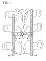
- FIG. 1 there is shown the cross connector assembly of the present invention, generally denoted at 10 connecting a pair of rods, 12 and 14, of a spinal osteosynthesis system. This interconnection is preferably accomplished by sizing the cross connector 10 to extend between rods 12 and 14.
- both rod gripping elements 18 and 20 include bodies with hook portions 22 formed at one end. Also in the preferred embodiment, both rod gripping portions include angled holes 24 and 26 which are threaded to accommodate a set screw (not shown) utilized to lock one of the rods 12, 14 within the hooked portion 22.
- First rod gripping element 18 includes an extension arm 28 which may be in the form of a rod or shaft formed integrally with the connecting element 18, such as by welding or by machining both the gripping element 18 and the arm 28 from a single piece of material. Alternately the end of arm 28 adjacent rod gripping element 18 maybe threaded and screwed into a corresponding threaded bore formed on surface 30 of rod gripping element 18.
- Rod gripping element 20 includes a bearing portion 32 formed on an end thereof opposite the end including hook portion 20.
- the bearing portion includes an upwardly facing surface 34 and a first bearing surface 36 surrounding a bore 38.
- Bore 38 includes a second bearing surface 40 internal of bore 38 extending parallel to axis 42.
- a pivot element generally denoted as 44 includes a head 45 having a surface 46 and a cylindrical bearing surface 48 and a threaded portion 50. Also included is a lock nut 52 with a threaded bore 56.
- FIGS. 4A and 4B there is shown an elevation view of pivot element 44 in an unassembled condition in 4A and assembled with lock nut 52 in FIG. 4B.
- arm 28 is shown in cross-section.
- head 45 of pivot element 44 includes a bore composed of two circular sections 58 and 60 having different diameters.
- the diameter of circular section 60 closely matches that of the side diameter of arm 28 which, in the preferred embodiment, is circular in cross-section.
- the circular portion 58 has a somewhat larger diameter and, in the preferred embodiment has a center 61 offset from the center 63 of circular portion 60. This results in the bore in head 45 having an eccentric shape.
- cylindrical bearing surface 40 of bore 38 is positioned to pivot on bearing surface 48 of pivot element 44 when completely assembled.
- the diameter of arm 28 and circular bore portions 58 and 60 and the location of surface 46 are dimensioned such that upon complete assembly a portion of arm 28 always extends beyond surface 46, leaving a gap "A" between surface 46 and surface 36.
- Pivot element 44 may be permanently assembled onto arm 28 during manufacture. This permanent mounting is accomplished by placing pivot element 44 on the arm and forming a flange 62 at the free end of arm 28 and then permanently attach the arm to the body of the first gripping element. Flange 62 maybe formed by upsetting the material at the free end of the arm. The diameter of upset portion 62 is larger than the opening in pivot element 44 formed by combined circular bores 58 and 60. Thus, while pivot element 44 is freely slidable on arm 28, it cannot become disengaged. Alternatively, the end of arm 28 may be threaded into a bore in rod gripping element 18 in which case the pivot element is placed on arm 28 prior to being threaded into element 18. The flange 62 will still keep the pivot element 44 from disengaging. This procedure can be done at the time of use.
- FIGS. 5 through 7 Alternate embodiments are shown in FIGS. 5 through 7.
- the cross connector is the same as that described above, except for the gripping members.
- the rod gripping elements 18 and 20 are in the form of hooks 22a and 22b which face away for each other. Hook portions 22a and 22b face away from each other so that even closely spaced rods 12, 14 can be accommodated by the cross connector 10.
- the cross connector By facing the curved portions of the hooks away from each other, the cross connector can fit completely between the rods 12, 14 and grip the rods from the inside.
- Such a connector is shorter in length than a cross connector with hooks facing towards each other and designed to grip the rods from the outside.
- the positioning of angled holes 24 and 26 are oriented so that the set screw is directed in the direction of the rod to be gripped.
- a cross connector which includes hook portions 22c and 22d which face in the same direction, thus allowing the cross connector to be slid into position by movement of cross connector 10 and rod gripping elements 18 and 20 in the same direction with respect to the rods 12, 14.
- one of the holes, 24 or 26 is oppositely oriented so that the set screw properly engages the rod.
- This design also allows somewhat closer spacing between rods 12, 14 than if the hooks 22 of FIG. 1 which face each other.
- FIG. 7 there is shown two rod gripping elements 18a and 18b similar in design to rod gripping element 18 shown in FIG. 3.
- an elongated arm 28a is provided which extends between elements 18a and 18b through a pivot element 44 on each of the elements 18a and 18b.
- Pivot element 44 is identical to that shown in FIGS. 4A and 4B so that elements 18a and 18b may be spaced in the proximal distal direction along rods 12 and 14.
- Rod 28a includes stop 62 and on each end to prevent disassembly of the structure.
- the length of rod 28a may be from 30 to 100 mm and, if necessary, elongated rod 28a may be bent in the posterior direction with the use of a rod bending instrument (not shown) to avoid any bony masses in the spine area.
- rod 28a may be bent in other directions, if necessary, to avoid contacting bone.
- the use of two pivot elements 44 enables rod gripping portions 18a and 18b to be oriented in a multitude of angular orientations.
- cross connector 10 maybe loosely assembled by placing bore 38 over the threaded portion 50 of the pivot element 44 and partially tightening lock nut 52 on threaded portion 50.
- the rod gripping elements 18 and 20 may then be positioned in any angular relationship with respect to one another and can also be moved towards or away from one another along axis 64 which extends along arm 28.
- hook portions 22 are placed over and locked onto rods 12, 14 by set screws (not shown), then the cross connector assembly maybe locked in a fixed position.
- the diameter of the arm or rod 28 is 3.0 + .00 -.05 mm and the diameter of the circular bore 60 is 3.0 + .05 - .00 mm with the distance from the center of bore 60 to surface 46 being 1.25 + 0 - .05 mm so that a gap "A" of approximately .25 mm is present when the assembly is tightened.
- the dimension of the length of the arms or rods 28 in the preferred embodiment is 12-42 mm with the upset portion at the end of the arm being 3.4 mm in diameter which is larger than the narrowest portion of the intersecting bores 58 and 60.
- the arm may be removable in which case the arms of different length are screwed into element 18 or, alternatively, different elements 18 may be provided with permanent arms of different lengths.
- the head 45 of pivot element may be circular or may be part circular with a flatter portion facing body 22 of element 18 when mounted on arm 28. This allows the pivot element to be mounted closer to element 18 when mounted on arm 28 than would be the case if head 45 were entirely circular
Description
- The present invention relates to a vertebral osteosynthesis device that can be used to brace a spine, for example, following accidental fracture, or to strengthen or brace a deviated spine, as in the case scoliosis or kyphosis. More particularly, this invention is related to a novel cross connector which fixes the location and enhances the rigidity of longitudinally extending rods anchored to the spine.
- As is known, from, for example, U.S. Patent 5,005,562 to Cotrel, a pair of posterior rods may be coupled to the back of a spinal column by hooks held by screws supported by the pedicles of the vertebra. Generally, there are two rigid and substantially parallel support rods disposed one on each side of the spine supported by pedicle screws or hooks. These vertically aligned rods stabilize both short and long segments of the spine. Implantation of such a device requires the rods to be shaped to adapt to the curve in one or two planes of the spine, whether these are nature curves or curves resulting from scoliosis or kyphosis.
- In order to provide enhanced rigidity, especially torsional rigidity, the pair of rods usually includes cross connecting devices which couple the rods together transverse to their longitudinal axis, i.e. transverse to an axis extending in the vertical direction when an individual is standing.
- As can be seen from U.S. Patent 5,005,562 these cross connector devices include a plurality hook shaped gripping elements which receive the rod. These elements are fixed to the rods by set screws which extend through a wall of the hook. Since the rods may be curved in the medial-lateral direction and the distance between the pair of rods may vary consequently, a method for varying the horizontal distance between the hooks is required. As can be seen in U.S. Patent 5,005,562, one solution is to provide a threaded transverse rod on which the hooks may be threaded for movement therealong. Of course, this limits the adjustibility of the hooks, depending on the fineness of the thread and the required angular orientation necessary to engage the vertical rods.
- Consequently, Cotrel, in his later patents, 5,601,552 and 5,651,789 uses a transverse bar of polygonal shape which allows the hooks to slide and be fixed in any relative horizontal position along the bar. However, such a system exhibits only one degree of freedom since the hook surfaces always move in the same plane.
- In U.S. Patent 5,667,507 to Corin, et al., a cross locking member is provided, which includes an additional degree of freedom, allowing rotation in the vertical plane as well as length adjustment in the horizontal direction. Thus, two degrees of freedom are provided. Similarly, U.S. Patent 5,752,955 provides two degrees of freedom by allowing rotation around a horizontally extending axis as well as allowing equalized extension via a telescoping connection between the hook bodies.
- U.S. Patent 5,443,465 to Pennig discloses a fracture fixation device having multiple degrees of freedom. However, this device requires several joints which have to be independently locked to fix the device in a given position.
- U.S. Patent 5,716,355 to Jackson, et al. relates to a pair of connectors slideable along each to two parallel spinal rods and having swivel connections to fix the final orientation of a transverse rod relative to the spinal rod. This design requires both connectors to be independently adjusted and locked to fix the transverse rod in its final position.
- U.S. Patent 5,261,907 to Vignaud, et al. relates to a cross connecting device having a pair of rods and a pair of clamps which can be fixed in place, utilizing a screw arrangements. This device is difficult to assemble because it includes two clamps, each receiving its own extension arm which arms are independently adjustable within the clamps.
- A further US Patent 5 709 684 (The preamble of claim 1 is based on this document.) is known in which a variable length cross-link device is disclosed, having two hook elements connected together by a pivot element. The pivot element is provided with a nut and a thread with which the hook elements may be crush locked together.
- It is therefore an object of the present invention to provide a cross connector device having a low profile but allowing for a substantial degree of freedom between the hooks at either end of the device.
- It is also an object of the present invention to provide a cross connector device which, while providing multiple degrees of freedom, provides a surgeon with the ability to lock the device on a spinal rod with a set screw in a given orientation with a single locking mechanism, using only two tools, one for the locking mechanism and one for the set screw.
- These and other objects of the invention are achieved by the present invention, which is a locking variable cross connector device which may be affixed to the rods of a dual rod spinal implant apparatus. This cross connector device includes a pair of rod engaging elements in the form of hooks.
- The cross connector or link for connecting spinal rods of the present invention includes a first rod gripping element which, in the preferred embodiment, is in the form of a hook formed on a first end of the rod gripping element and including an arm or rod extending from a second end thereof along a first axis. A second rod gripping element is provided which also includes hook formed on a first end thereof and a bearing portion with a bearing surface surrounding a bore or hole integrally formed on a second end thereof. A pivot element is slidably and rotatably coupled to the arm on the first rod gripping element, via a bore in the pivot element for movement therealong and for rotation about the first axis. The pivot element includes a bearing surface engageable with the bearing surface formed on the second element. These bearing surfaces allow relative rotation between the pivot element and the second rod gripping element about a second axis which is not parallel to the first axis.
- In the preferred embodiment, the second axis is perpendicular to the first axis to allow relative angular adjustment between the two hook portions in the vertical plane of the spine. As used herein, the vertical plane refers to the plane through the spine in the medial lateral direction which is parallel to the front or coronal plane.
- The pivot element has a first clamping portion associated with the bore therein which engages the arm and a second clamping portion in the form of a lock nut which engages the bearing member on the second rod gripping element. The clamping portions of the pivot element are designed to clamp the arm and a bearing surface on the second rod gripping element to prevent all rotation about the first and second axis and all movement along the arm. This may be accomplished by the frictional engagement between a bearing surface on the second element while clamped between the lock nut, and the surface of the arm and the engagement of the first clamping portion in the bore of the pivot element contacting the opposite side of the arm.
- In the preferred embodiment, the arm on the first bearing element may be in the form of a longitudinally extending rod or shaft having a circular cross section and the pivot element may include a head portion having the first clamping portion in the form of a part circular bore therethrough for receiving the arm. In the preferred embodiment, the cross section of the bore includes a first circular part having a diameter larger than the diameter of the arm and a second circular part having a diameter closely matching the diameter of the circular rod or arm. The centers of the two circular bore parts may be offset from one another, thus forming a pair of concentric circular areas. At the end of the pivot element opposite the head, the pivot element may be in the form of a threaded rod or screw shank which extends from the head portion along an axis which, upon assembly of the first and second rod gripping elements and the pivot element, is coaxial with the second axis.
- In the preferred embodiment, the bore in the head of the pivot element extends along an axis transverse to the axis of the threaded portion of the pivot element and, upon assembly on the arm, is parallel to the first axis. Upon clamping of the assembled cross connector, the arm is moved into the second smaller circular part of the bore so the second circular part and the arm are essentially coaxial.
- In the preferred embodiment, there are two bearing surfaces on the second rod connecting element. First is a tlat surface area which surrounds the hole through the second end which receives the threaded portion of the pivot element. A second bearing surface is formed on the inner cylindrical surface located within the hole of the second element. This second bearing contacts a cylindrical bearing surface formed around the pivot element intermediate the head and the threaded portion. In the preferred embodiment, the bearing member of the second rod connecting element is in the form of a plate or flange having a hole therethrough for receiving the cylindrical bearing surface of the pivot element with the thickness of the plate determining the length of the cylindrical bearing surface which contacts the cylindrical bearing surface on the pivot element. The surface of the plate facing the head of the pivot element acts as the first bearing surface and engages the arm on the first rod gripping element when the assembly is locked. This is because the bore in the head of the pivot element forming the first clamping portion extends through a portion of the cylindrical bearing surface between the head and the threaded portion with the diameter of the arm dimensional to extend into the cylindrical bearing surface when the arm is fully positioned in the second part of the bore in the head. Thus, the first bearing surface surrounding the hole on the second end of the second rod gripping element engages the outer surface of the arm or rod when the second element is positioned on the threaded portion of the pivot element with the bearing surface in the bore on the second element engaging the cylindrical bearing surface on the pivot element. Consequently, a gap is always left between a surface of the head adjacent the cylindrical bearing surface and the adjacent first bearing surface on the second element.
- A lock nut engageable with threaded portion of the pivot element acts against the area of the second element surrounding said bore on the side opposite said first bearing surface and, upon tightening, moves the first bearing surface towards the head of the bearing element and into engagement with the outer surface of the arm. Upon sufficient tightening of the lock nut on the threaded portion of the pivot element, the first bearing surface on the second element forces the arm from the first circular part in the head to the smaller second circular part in the head and causing the frictional engagement between all of the relatively movable parts to lock the assembly together in a fixed position.
- Conversely, loosening the locking nut permits adjustment of the length of the device along the first axis and allows rotation of the second axis about the first axis by pivoting the head of the clamping element about the arm and changing the angular relationship between the hooked portions by rotation of the second element about the second axis.
- The first rod gripping element, the second rod gripping element, and the clamping element may be held loosely together by a stop on the end of the arm or rod. The stop maybe made by upsetting the material at the end of the arm, thus forming a diameter greater than the larger first diameter of the bore in the head to thereby prevent the head from disengaging from the arm once assembled. The lock nut can be placed loosely on the threaded portion of the pivot element, thereby allowing relative motion but preventing the unintentional disassembly of the cross connector.
- The extension arm on the first element may either be integral with the gripping element or maybe pre-assembled thereto in any manner or the arm may have a threaded end threaded into body of the first rod connecting element so that different length arms maybe utilized with the clamping element at the time of surgery.
- These and other objects and advantages of the present invention will become apparent from the following description of the accompanying drawings, which disclose several embodiments of the invention. It is to be understood that the drawings are to be used for purposes of illustration only and not as a definition of the invention.
- In the drawings, wherein similar reference characters denote similar elements throughout the several views:
- FIG. 1 is an elevation view of the vertical plane of the spine, including the cross connectors of the present invention coupling a pair of stabilizing rods mounted on the vertebra pedicles;
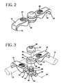
- FIG. 2 is an isometric view of one of the cross connector shown in FIG. 1;
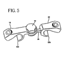
- FIG. 3 is an exploded view of the cross connector shown in FIG. 1 mounted on a pair of rods;
- FIG. 4A is an elevation view of the pivot element of the present, with the arm positioned therein;
- FIG. 4B is an elevation view of the pivot element and pivot arm of FIG. 4A being clamped together by a locking nut;
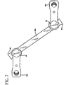
- FIG. 5 is an isometric view of the cross connector of the present invention, including two gripping portions facing away from one another;
- FIG. 5A is an elevation view of the cross connector embodiment shown in FIG. 5;
- FIG.6 is an isometric view of the cross connector of the present invention showing gripping portions both facing in the same direction;
- FIG. 6A is an elevation view of the cross connector shown in FIG. 6; and
- FIG. 7 is a top view of the cross connector of the present invention, including an-intermediate rod connecting a pair of pivoted rod gripping portions.
-
- Referring to FIG. 1, there is shown the cross connector assembly of the present invention, generally denoted at 10 connecting a pair of rods, 12 and 14, of a spinal osteosynthesis system. This interconnection is preferably accomplished by sizing the
cross connector 10 to extend betweenrods - Referring to FIGS. 2 and 3, there is shown the
cross connector 10 of the present invention, which consists of a firstrod gripping element 18 and a secondrod gripping element 20. In the preferred embodiment, bothrod gripping elements hook portions 22 formed at one end. Also in the preferred embodiment, both rod gripping portions includeangled holes rods portion 22. - First
rod gripping element 18 includes anextension arm 28 which may be in the form of a rod or shaft formed integrally with the connectingelement 18, such as by welding or by machining both thegripping element 18 and thearm 28 from a single piece of material. Alternately the end ofarm 28 adjacentrod gripping element 18 maybe threaded and screwed into a corresponding threaded bore formed onsurface 30 ofrod gripping element 18. -
Rod gripping element 20 includes a bearingportion 32 formed on an end thereof opposite the end includinghook portion 20. The bearing portion includes an upwardly facingsurface 34 and afirst bearing surface 36 surrounding abore 38.Bore 38 includes asecond bearing surface 40 internal ofbore 38 extending parallel toaxis 42. - A pivot element generally denoted as 44 includes a
head 45 having asurface 46 and acylindrical bearing surface 48 and a threadedportion 50. Also included is alock nut 52 with a threadedbore 56. - Referring now to FIGS. 4A and 4B, there is shown an elevation view of
pivot element 44 in an unassembled condition in 4A and assembled withlock nut 52 in FIG. 4B. In both views,arm 28 is shown in cross-section. As can be best seen in FIG. 4A,head 45 ofpivot element 44 includes a bore composed of twocircular sections circular section 60 closely matches that of the side diameter ofarm 28 which, in the preferred embodiment, is circular in cross-section. Thecircular portion 58 has a somewhat larger diameter and, in the preferred embodiment has acenter 61 offset from thecenter 63 ofcircular portion 60. This results in the bore inhead 45 having an eccentric shape. - As can be best seen in FIG. 4B,
cylindrical bearing surface 40 ofbore 38 is positioned to pivot on bearingsurface 48 ofpivot element 44 when completely assembled. In addition, the diameter ofarm 28 andcircular bore portions surface 46 are dimensioned such that upon complete assembly a portion ofarm 28 always extends beyondsurface 46, leaving a gap "A" betweensurface 46 andsurface 36. -
Pivot element 44 may be permanently assembled ontoarm 28 during manufacture. This permanent mounting is accomplished by placingpivot element 44 on the arm and forming aflange 62 at the free end ofarm 28 and then permanently attach the arm to the body of the first gripping element.Flange 62 maybe formed by upsetting the material at the free end of the arm. The diameter ofupset portion 62 is larger than the opening inpivot element 44 formed by combined circular bores 58 and 60. Thus, whilepivot element 44 is freely slidable onarm 28, it cannot become disengaged. Alternatively, the end ofarm 28 may be threaded into a bore inrod gripping element 18 in which case the pivot element is placed onarm 28 prior to being threaded intoelement 18. Theflange 62 will still keep thepivot element 44 from disengaging. This procedure can be done at the time of use. - Alternate embodiments are shown in FIGS. 5 through 7. In the embodiment of FIG. 5 and 5A, the cross connector is the same as that described above, except for the gripping members. In the embodiment of FIG. 5, the
rod gripping elements hooks Hook portions rods cross connector 10. By facing the curved portions of the hooks away from each other, the cross connector can fit completely between therods angled holes - With regard to FIGS. 6 and 6A, a cross connector is shown which includes
hook portions cross connector 10 androd gripping elements rods rods hooks 22 of FIG. 1 which face each other. - Referring to FIG. 7, there is shown two
rod gripping elements rod gripping element 18 shown in FIG. 3. However, instead of anarm 28 being fixed to one of the rod gripping elements, anelongated arm 28a is provided which extends betweenelements pivot element 44 on each of theelements Pivot element 44 is identical to that shown in FIGS. 4A and 4B so thatelements rods Rod 28a includes stop 62 and on each end to prevent disassembly of the structure. In the preferred embodiment, the length ofrod 28a may be from 30 to 100 mm and, if necessary,elongated rod 28a may be bent in the posterior direction with the use of a rod bending instrument (not shown) to avoid any bony masses in the spine area. Of course,rod 28a may be bent in other directions, if necessary, to avoid contacting bone. The use of twopivot elements 44 enablesrod gripping portions - During assembly,
cross connector 10 maybe loosely assembled by placingbore 38 over the threadedportion 50 of thepivot element 44 and partially tighteninglock nut 52 on threadedportion 50. Therod gripping elements axis 64 which extends alongarm 28. Oncehook portions 22 are placed over and locked ontorods - This is accomplished by tightening
lock nut 52 which movessurface 36 of bearingportion 32 towardssurface 46 of the pivot element untilsurface 36 engages the outercurved surface 66 ofarm 28. At this point,arm 28 is moved out ofcircular bore 58 intocircular bore 60 and since the parts are dimensioned so that gap "A" is always present,surface 36forces rod 28 into the tightly conformingbore 60. The dimensions of the outer diameter ofrod 28 and the inner surface ofbore 60 closely match such that sufficient friction is created to prevent both the rotation of pivot element with respect toarm 28 and the sliding ofpivot element 44 with respect toarm 28. Likewise, the pressure oflock nut 52 onsurface 34 of bearingportion 32 is sufficient to prevent rotation aboutaxis 42. Thus, the cross connector is locked in position. If the surgeon wishes to rearrange the rod system, he merely loosensnut 52 which then permits rotation aboutaxis arm 28. - In the preferred embodiment, the diameter of the arm or
rod 28 is 3.0 + .00 -.05 mm and the diameter of thecircular bore 60 is 3.0 + .05 - .00 mm with the distance from the center ofbore 60 to surface 46 being 1.25 + 0 - .05 mm so that a gap "A" of approximately .25 mm is present when the assembly is tightened. The dimension of the length of the arms orrods 28 in the preferred embodiment is 12-42 mm with the upset portion at the end of the arm being 3.4 mm in diameter which is larger than the narrowest portion of the intersecting bores 58 and 60. As indicated above, the arm may be removable in which case the arms of different length are screwed intoelement 18 or, alternatively,different elements 18 may be provided with permanent arms of different lengths. Thehead 45 of pivot element may be circular or may be part circular with a flatterportion facing body 22 ofelement 18 when mounted onarm 28. This allows the pivot element to be mounted closer toelement 18 when mounted onarm 28 than would be the case ifhead 45 were entirely circular - While there have been described and illustrated cross connector devices for coupling dual rods of orthopaedic apparatus together and providing enhanced stability thereto, it will be apparent to those skilled in the art that variations and modifications are possible without deviating from the principle of the present invention which shall be limited solely by the scope of the claims appended hereto.
Claims (15)
- A spinal cross connector (10) comprising:characterised by said pivot element havinga first element (18) having a body, a rod gripping portion (22) formed on a first end of said body and a circular rod (28) extending along a first axis (64) from a second end of said body;a second element (20) having a body, a rod gripping portion (22) formed on a first end of said body and a flange having a bearing portion including a bore (38), extending from a second end of said body, said bore (38) including an internal cylindrical bearing surface (40);a pivot element (44) having a head portion (45), including a bore therethrough for engaging said rod (28), a threaded portion (50) extending from said head (45) along a second axis (42) and a lock nut (52) operatively engageable with said threaded portion (50) on said pivot element (44)
a generally cylindrical bearing surface (48) having a diameter greater than the diameter of the threaded portion (50), said bearing surface (48) being engageable with said cylindrical bearing surface (40) of said bore (38), such that said cylindrical bearing surface (40) of said bore (38) is pivotable on said bearing surface (48) of said pivot element (44). - The cross connector of claim 1, wherein said rod gripping portions (22) are hook shaped.
- The cross connector of claim 2, wherein each of said hook shaped gripping portions (22) has a curved portion.
- The cross connector of claim 3, wherein said curved portion on said rod gripping portions (22) face in the same direction.
- The cross connector as set forth in claim 1, wherein a cross section of said bore in said pivot head (45) includes a first circular part (58) having a diameter larger than the diameter of said rod (28) and a second circular part (60) having a diameter closely matching the diameter of said rod (28).
- The cross connector as set forth in claim 5, wherein the centers of said first and second circular parts (58, 60) of said bore are offset from one-another.
- The cross connector as set forth in claim 5, wherein said bore extends along an axis transverse (64) to said second axis (42).
- The cross connector as set forth in claim 1, wherein said first and second axis (64, 42) are perpendicular.
- The cross connector as set forth in claim I, wherein said cylindrical bearing surface (40) of said bore (38) extends between said head portion (45) and said threaded portion (50) of said pivot element (44).
- The cross connector as set forth in claim 9, wherein said bearing portion of said second element (20) is in the form of a plate having a bore (38) for receiving the cylindrical bearing surface (48) of said pivot element (44) and includes a planar bearing surface (36) surrounding said bore (38).
- The cross connector as set forth in claim 1, wherein said bore in said head (45) extends through a portion of said cylindrical bearing surface (40).
- The cross connector as set forth in claim 11, wherein a cross section of said rod (28) extends into said cylindrical bearing surface (40) when said rod (28) is positioned in a second circular part (60) of said bore having a diameter closely matching the diameter of said rod (28).
- The cross-connector as set forth in claim 12, wherein said bearing surface (36) on said second element (20) engages said rod (28) when the second element (20) is positioned on said threaded portion (50) with said bore (38) on said rod gripping element (22) engaging said cylindrical bearing surface (38) on said pivot element (44) to permit relative rotation therebetween.
- The cross connector as set forth in claim 13, further including a lock nut (52) threaded onto said threaded portion (50) and clamping said planar bearing surface (36) of said second element (20) against said rod (28) and positioning said rod (28) within said circular part of said bore of said pivot element (44).
- The cross connector as set forth in claim 1, wherein said rod (28) has a stop (62) formed on a free end thereof at the second end of said first element (18), said stop (62) having a cross section larger than the cross section of said bore in said in said pivot element (44).
Applications Claiming Priority (2)
| Application Number | Priority Date | Filing Date | Title |
|---|---|---|---|
| US419869 | 1982-09-20 | ||
| US09/419,869 US6217578B1 (en) | 1999-10-19 | 1999-10-19 | Spinal cross connector |
Publications (3)
| Publication Number | Publication Date |
|---|---|
| EP1093761A2 EP1093761A2 (en) | 2001-04-25 |
| EP1093761A3 EP1093761A3 (en) | 2001-11-28 |
| EP1093761B1 true EP1093761B1 (en) | 2003-12-17 |
Family
ID=23664089
Family Applications (1)
| Application Number | Title | Priority Date | Filing Date |
|---|---|---|---|
| EP00120670A Expired - Lifetime EP1093761B1 (en) | 1999-10-19 | 2000-09-21 | Spinal cross connector |
Country Status (6)
| Country | Link |
|---|---|
| US (1) | US6217578B1 (en) |
| EP (1) | EP1093761B1 (en) |
| JP (1) | JP2001137255A (en) |
| AU (1) | AU770026B2 (en) |
| CA (1) | CA2321354C (en) |
| DE (1) | DE60007256T2 (en) |
Cited By (2)
| Publication number | Priority date | Publication date | Assignee | Title |
|---|---|---|---|---|
| US7744632B2 (en) | 2006-12-20 | 2010-06-29 | Aesculap Implant Systems, Inc. | Rod to rod connector |
| US7927355B2 (en) | 2003-10-22 | 2011-04-19 | Pioneer Surgical Technology, Inc. | Crosslink for securing spinal rods |
Families Citing this family (126)
| Publication number | Priority date | Publication date | Assignee | Title |
|---|---|---|---|---|
| DE19914232B4 (en) * | 1999-03-29 | 2012-08-30 | Signus Medizintechnik Gmbh | Device for stabilizing vertebral bodies of a spinal column |
| EP1743585B1 (en) * | 1999-03-30 | 2007-12-05 | Howmedica Osteonics Corp. | Apparatus for spinal stabilization |
| US6283967B1 (en) * | 1999-12-17 | 2001-09-04 | Synthes (U.S.A.) | Transconnector for coupling spinal rods |
| US6432108B1 (en) * | 2000-01-24 | 2002-08-13 | Depuy Orthopaedics, Inc. | Transverse connector |
| US20060241602A1 (en) * | 2000-06-06 | 2006-10-26 | Jackson Roger P | Hooked transverse connector for spinal implant system |
| US6524310B1 (en) * | 2000-08-18 | 2003-02-25 | Blackstone Medical, Inc. | Surgical cross-connecting apparatus having locking lever |
| US6802844B2 (en) * | 2001-03-26 | 2004-10-12 | Nuvasive, Inc | Spinal alignment apparatus and methods |
| TW524094U (en) * | 2001-05-02 | 2003-03-11 | Jung-Chiuan Ye | Retaining and recovering apparatus for spines |
| US6793657B2 (en) * | 2001-09-10 | 2004-09-21 | Solco Biomedical Co., Ltd. | Spine fixing apparatus |
| US20030114853A1 (en) * | 2001-10-12 | 2003-06-19 | Ian Burgess | Polyaxial cross connector |
| US20060079892A1 (en) * | 2001-10-31 | 2006-04-13 | Suranjan Roychowdhury | Adjustable tandem connectors for corrective devices for the spinal column and other bones and joints |
| US7066938B2 (en) * | 2002-09-09 | 2006-06-27 | Depuy Spine, Inc. | Snap-on spinal rod connector |
| US8029543B2 (en) * | 2002-10-28 | 2011-10-04 | Warsaw Othopedic, Inc. | Multi-axial, cross-link connector system for spinal implants |
| WO2004039268A1 (en) * | 2002-10-28 | 2004-05-13 | Sdgi Holdings, Inc. | Multi-axial, cross-link connector system for spinal implants |
| US7918876B2 (en) | 2003-03-24 | 2011-04-05 | Theken Spine, Llc | Spinal implant adjustment device |
| US7160301B2 (en) * | 2003-07-01 | 2007-01-09 | Seaspine, Inc. | Transverse connector system |
| US7771474B2 (en) * | 2003-07-01 | 2010-08-10 | Seaspine, Inc. | Transverse connector system |
| AU2004266737B2 (en) | 2003-08-20 | 2010-05-13 | Warsaw Orthopedic, Inc. | Multi-axial orthopedic device and system, e.g. for spinal surgery |
| US7255714B2 (en) | 2003-09-30 | 2007-08-14 | Michel H. Malek | Vertically adjustable intervertebral disc prosthesis |
| US7481827B2 (en) * | 2003-10-09 | 2009-01-27 | Synthes (U.S.A.) | Linking transconnector for coupling spinal rods |
| US20050080414A1 (en) * | 2003-10-14 | 2005-04-14 | Keyer Thomas R. | Spinal fixation hooks and method of spinal fixation |
| US7862586B2 (en) * | 2003-11-25 | 2011-01-04 | Life Spine, Inc. | Spinal stabilization systems |
| US8480712B1 (en) | 2004-01-06 | 2013-07-09 | Nuvasive, Inc. | System and method for performing spinal fixation |
| US7833251B1 (en) | 2004-01-06 | 2010-11-16 | Nuvasive, Inc. | System and method for performing spinal fixation |
| US7645294B2 (en) * | 2004-03-31 | 2010-01-12 | Depuy Spine, Inc. | Head-to-head connector spinal fixation system |
| US7717939B2 (en) | 2004-03-31 | 2010-05-18 | Depuy Spine, Inc. | Rod attachment for head to head cross connector |
| US20050228377A1 (en) * | 2004-04-07 | 2005-10-13 | Depuy Spine, Inc. | Spinal cross-connectors |
| US20050234438A1 (en) * | 2004-04-15 | 2005-10-20 | Mast T D | Ultrasound medical treatment system and method |
| US7717938B2 (en) | 2004-08-27 | 2010-05-18 | Depuy Spine, Inc. | Dual rod cross connectors and inserter tools |
| US7959653B2 (en) * | 2004-09-03 | 2011-06-14 | Lanx, Inc. | Spinal rod cross connector |
| US20070225712A1 (en) * | 2004-10-20 | 2007-09-27 | Moti Altarac | Systems and methods for posterior dynamic stabilization of the spine |
| US9339301B2 (en) | 2004-12-30 | 2016-05-17 | Mark A. Barry | System and method for aligning vertebrae in the amelioration of aberrant spinal column deviation conditions |
| US20060271045A1 (en) * | 2005-05-27 | 2006-11-30 | Depuy Spine, Inc. | Spinal cross-connector |
| KR20080040684A (en) * | 2005-07-18 | 2008-05-08 | 동명 전 | Bi-polar bone screw assembly |
| US7628799B2 (en) * | 2005-08-23 | 2009-12-08 | Aesculap Ag & Co. Kg | Rod to rod connector |
| US7833248B2 (en) * | 2006-03-10 | 2010-11-16 | Custom Spine, Inc. | Spinal cross-connector |
| US7695500B2 (en) * | 2006-03-10 | 2010-04-13 | Custom Spine, Inc. | Polyaxial occipital plate |
| US7780704B2 (en) * | 2006-03-10 | 2010-08-24 | Custom Spine, Inc. | Spinal cross-connector |
| WO2007114834A1 (en) | 2006-04-05 | 2007-10-11 | Dong Myung Jeon | Multi-axial, double locking bone screw assembly |
| US7837714B2 (en) * | 2006-04-10 | 2010-11-23 | Warsaw Orthopedic, Inc. | Methods and devices for the interconnection of bone attachment devices |
| US7722648B2 (en) * | 2006-04-10 | 2010-05-25 | Warsaw Orthopedic, Inc. | Crosslink interconnection of bone attachment devices |
| US8043337B2 (en) | 2006-06-14 | 2011-10-25 | Spartek Medical, Inc. | Implant system and method to treat degenerative disorders of the spine |
| US7842071B2 (en) | 2006-07-11 | 2010-11-30 | Pioneer Surgical Technology, Inc. | Transverse connector |
| US20080027444A1 (en) * | 2006-07-28 | 2008-01-31 | Malek Michel H | Bone anchor device |
| US7922746B2 (en) * | 2006-08-31 | 2011-04-12 | Warsaw Orthopedic, Inc. | Spinal rod extenders and methods of use |
| JP5187594B2 (en) | 2006-09-26 | 2013-04-24 | ジンテス ゲゼルシャフト ミット ベシュレンクテル ハフツング | Transformer connector |
| US8361117B2 (en) | 2006-11-08 | 2013-01-29 | Depuy Spine, Inc. | Spinal cross connectors |
| US20080140124A1 (en) * | 2006-12-07 | 2008-06-12 | Dong Myung Jeon | Spinal rod transverse connector system |
| BRPI0806432A2 (en) * | 2007-01-23 | 2011-09-13 | Bio Smart Co Ltd | spacer to be used in a surgical operation for spinal processes |
| WO2008094572A2 (en) * | 2007-01-30 | 2008-08-07 | Dong Myung Jeon | Anterior cervical plating system |
| US20080281361A1 (en) * | 2007-05-10 | 2008-11-13 | Shannon Marlece Vittur | Posterior stabilization and spinous process systems and methods |
| US7947066B2 (en) * | 2007-05-22 | 2011-05-24 | K2M, Inc. | Universal transverse connector device |
| US8083772B2 (en) | 2007-06-05 | 2011-12-27 | Spartek Medical, Inc. | Dynamic spinal rod assembly and method for dynamic stabilization of the spine |
| US8021396B2 (en) | 2007-06-05 | 2011-09-20 | Spartek Medical, Inc. | Configurable dynamic spinal rod and method for dynamic stabilization of the spine |
| US8114134B2 (en) | 2007-06-05 | 2012-02-14 | Spartek Medical, Inc. | Spinal prosthesis having a three bar linkage for motion preservation and dynamic stabilization of the spine |
| US8070776B2 (en) | 2007-06-05 | 2011-12-06 | Spartek Medical, Inc. | Deflection rod system for use with a vertebral fusion implant for dynamic stabilization and motion preservation spinal implantation system and method |
| US8147520B2 (en) | 2007-06-05 | 2012-04-03 | Spartek Medical, Inc. | Horizontally loaded dynamic stabilization and motion preservation spinal implantation system and method |
| US8048115B2 (en) | 2007-06-05 | 2011-11-01 | Spartek Medical, Inc. | Surgical tool and method for implantation of a dynamic bone anchor |
| US8105359B2 (en) | 2007-06-05 | 2012-01-31 | Spartek Medical, Inc. | Deflection rod system for a dynamic stabilization and motion preservation spinal implantation system and method |
| US8092501B2 (en) | 2007-06-05 | 2012-01-10 | Spartek Medical, Inc. | Dynamic spinal rod and method for dynamic stabilization of the spine |
| US8048121B2 (en) | 2007-06-05 | 2011-11-01 | Spartek Medical, Inc. | Spine implant with a defelction rod system anchored to a bone anchor and method |
| US20080312697A1 (en) * | 2007-06-15 | 2008-12-18 | Robert Reid, Inc. | System and Method for Polyaxially Adjustable Bone Anchorage |
| US8308767B2 (en) * | 2007-09-19 | 2012-11-13 | Pioneer Surgical Technology, Inc. | Interlaminar stabilization system |
| AU2008304546A1 (en) | 2007-09-25 | 2009-04-02 | Synthes Gmbh | Transconnector |
| US8147519B2 (en) * | 2007-10-09 | 2012-04-03 | Warsaw Orthopedic, Inc. | Variable angle rod connectors and the methods of use |
| US9474554B2 (en) * | 2007-10-23 | 2016-10-25 | Lee A. Strnad | Spinal rod cross connector |
| WO2009076107A1 (en) * | 2007-12-13 | 2009-06-18 | Trinity Orthopedics, Llc | Spinal transverse connector |
| US20090171395A1 (en) * | 2007-12-28 | 2009-07-02 | Jeon Dong M | Dynamic spinal rod system |
| US8617214B2 (en) | 2008-01-07 | 2013-12-31 | Mmsn Limited Partnership | Spinal tension band |
| US8808332B2 (en) * | 2012-12-31 | 2014-08-19 | Globus Medical, Inc. | Method for stabilizing the spine |
| US20090192548A1 (en) * | 2008-01-25 | 2009-07-30 | Jeon Dong M | Pedicle-laminar dynamic spinal stabilization device |
| US20090194206A1 (en) * | 2008-01-31 | 2009-08-06 | Jeon Dong M | Systems and methods for wrought nickel/titanium alloy flexible spinal rods |
| US7935133B2 (en) | 2008-02-08 | 2011-05-03 | Mmsn Limited Partnership | Interlaminar hook |
| US20100030224A1 (en) | 2008-02-26 | 2010-02-04 | Spartek Medical, Inc. | Surgical tool and method for connecting a dynamic bone anchor and dynamic vertical rod |
| US8211155B2 (en) | 2008-02-26 | 2012-07-03 | Spartek Medical, Inc. | Load-sharing bone anchor having a durable compliant member and method for dynamic stabilization of the spine |
| US8097024B2 (en) | 2008-02-26 | 2012-01-17 | Spartek Medical, Inc. | Load-sharing bone anchor having a deflectable post and method for stabilization of the spine |
| US8267979B2 (en) | 2008-02-26 | 2012-09-18 | Spartek Medical, Inc. | Load-sharing bone anchor having a deflectable post and axial spring and method for dynamic stabilization of the spine |
| US8333792B2 (en) | 2008-02-26 | 2012-12-18 | Spartek Medical, Inc. | Load-sharing bone anchor having a deflectable post and method for dynamic stabilization of the spine |
| US8057515B2 (en) | 2008-02-26 | 2011-11-15 | Spartek Medical, Inc. | Load-sharing anchor having a deflectable post and centering spring and method for dynamic stabilization of the spine |
| US8016861B2 (en) * | 2008-02-26 | 2011-09-13 | Spartek Medical, Inc. | Versatile polyaxial connector assembly and method for dynamic stabilization of the spine |
| US8337536B2 (en) | 2008-02-26 | 2012-12-25 | Spartek Medical, Inc. | Load-sharing bone anchor having a deflectable post with a compliant ring and method for stabilization of the spine |
| US8083775B2 (en) | 2008-02-26 | 2011-12-27 | Spartek Medical, Inc. | Load-sharing bone anchor having a natural center of rotation and method for dynamic stabilization of the spine |
| US9060813B1 (en) | 2008-02-29 | 2015-06-23 | Nuvasive, Inc. | Surgical fixation system and related methods |
| US20090228046A1 (en) * | 2008-03-04 | 2009-09-10 | Laszlo Garamszegi | Transverse vertebral connector |
| WO2010006195A1 (en) | 2008-07-09 | 2010-01-14 | Amei Technologies, Inc. | Ankle arthrodesis nail and outrigger assembly |
| US8414584B2 (en) | 2008-07-09 | 2013-04-09 | Icon Orthopaedic Concepts, Llc | Ankle arthrodesis nail and outrigger assembly |
| US20100049252A1 (en) * | 2008-08-21 | 2010-02-25 | Southern Spine, Llc | Transverse Connector Device for Extending an Existing Spinal Fixation System |
| US8187304B2 (en) * | 2008-11-10 | 2012-05-29 | Malek Michel H | Facet fusion system |
| US20090143823A1 (en) * | 2008-11-13 | 2009-06-04 | Jeon Dong M | Transverse connector system for spinal rods |
| US8460342B2 (en) * | 2008-12-03 | 2013-06-11 | Eminent Spine Llc | Spinal cross-connector and method for use of same |
| US9492214B2 (en) * | 2008-12-18 | 2016-11-15 | Michel H. Malek | Flexible spinal stabilization system |
| US8998961B1 (en) | 2009-02-26 | 2015-04-07 | Lanx, Inc. | Spinal rod connector and methods |
| US9095380B2 (en) | 2009-03-31 | 2015-08-04 | Hamid R. Mir | Spinous process cross-link |
| JP2012524623A (en) | 2009-04-23 | 2012-10-18 | スパイナル・エレメンツ・インコーポレーテッド | Lateral connector |
| US8372120B2 (en) | 2009-05-20 | 2013-02-12 | Spine Wave, Inc. | Multi-axial cross connector |
| US8246657B1 (en) | 2009-06-29 | 2012-08-21 | Nuvasive, Inc. | Spinal cross connector |
| US20110106161A1 (en) * | 2009-10-30 | 2011-05-05 | Warsaw Orthopedic, Inc. | Position Retaining Crosslink |
| CN102695465A (en) | 2009-12-02 | 2012-09-26 | 斯帕泰克医疗股份有限公司 | Low profile spinal prosthesis incorporating a bone anchor having a deflectable post and a compound spinal rod |
| US9381044B2 (en) | 2010-01-26 | 2016-07-05 | Pioneer Surgical Technology, Inc. | Posterior spinal stabilization plate device |
| US9198696B1 (en) | 2010-05-27 | 2015-12-01 | Nuvasive, Inc. | Cross-connector and related methods |
| US20110307015A1 (en) | 2010-06-10 | 2011-12-15 | Spartek Medical, Inc. | Adaptive spinal rod and methods for stabilization of the spine |
| US8920471B2 (en) | 2010-07-12 | 2014-12-30 | K2M, Inc. | Transverse connector |
| US20120271353A1 (en) * | 2010-08-16 | 2012-10-25 | Mark Barry | System and method for aligning vertebrae in the amelioration of aberrant spinal column deviation conditions in patients requiring the accomodation of spinal column growth or elongation |
| EP2422727B1 (en) | 2010-08-27 | 2016-03-23 | Stryker European Holdings I, LLC | Bolt for use with an external fixator |
| US9301787B2 (en) | 2010-09-27 | 2016-04-05 | Mmsn Limited Partnership | Medical apparatus and method for spinal surgery |
| US8636774B2 (en) * | 2010-12-17 | 2014-01-28 | Spinal Usa, Inc. | Spinal implant apparatuses and methods of implanting and using same |
| US20120158064A1 (en) * | 2010-12-21 | 2012-06-21 | Matthew Kroll | Curved spinal cross-connector |
| US9247964B1 (en) | 2011-03-01 | 2016-02-02 | Nuasive, Inc. | Spinal Cross-connector |
| US9387013B1 (en) | 2011-03-01 | 2016-07-12 | Nuvasive, Inc. | Posterior cervical fixation system |
| CN103491889B (en) * | 2011-04-01 | 2016-10-12 | 新特斯有限责任公司 | Vertebra way of escape plate fixation system |
| WO2012139130A1 (en) | 2011-04-07 | 2012-10-11 | Blackstone Medical, Inc. | Clamp for spinal cross connecting device |
| US8556942B2 (en) | 2011-12-30 | 2013-10-15 | Blackstone Medical, Inc. | Occipito-cervical fixation assembly and method for constructing same |
| US8945186B2 (en) | 2011-12-30 | 2015-02-03 | Blackstone Medical, Inc. | Multi-axial spinal cross connecting device |
| US8430916B1 (en) | 2012-02-07 | 2013-04-30 | Spartek Medical, Inc. | Spinal rod connectors, methods of use, and spinal prosthesis incorporating spinal rod connectors |
| US8940020B2 (en) | 2012-04-06 | 2015-01-27 | DePuy Synthes Products, LLC | Rod connector |
| US8828056B2 (en) | 2012-04-16 | 2014-09-09 | Aesculap Implant Systems, Llc | Rod to rod cross connector |
| US8771319B2 (en) | 2012-04-16 | 2014-07-08 | Aesculap Implant Systems, Llc | Rod to rod cross connector |
| JP6189939B2 (en) | 2012-05-11 | 2017-08-30 | オーソペディアトリクス・コーポレーション | Surgical couplers and instruments |
| US9339309B1 (en) | 2012-10-11 | 2016-05-17 | Nuvasive, Inc. | Systems and methods for inserting cross-connectors |
| US9936982B2 (en) | 2012-11-26 | 2018-04-10 | Spinefrontier, Inc | System and method for translateral linking of bilateral spinal fixation rods |
| US9763705B2 (en) * | 2014-10-03 | 2017-09-19 | Globus Medical, Inc. | Orthopedic stabilization devices and methods for installation thereof |
| US9763703B2 (en) | 2015-05-05 | 2017-09-19 | Degen Medical, Inc. | Cross connectors, kits, and methods |
| US10413331B2 (en) | 2016-12-21 | 2019-09-17 | Spine Wave, Inc. | Spinal stabilization system with head to head cross connector |
| US11547453B2 (en) | 2018-12-12 | 2023-01-10 | Orthopediatrics Corp. | Bone anchor head extender |
| US11389209B2 (en) | 2019-07-19 | 2022-07-19 | Medos International Sarl | Surgical plating systems, devices, and related methods |
| US11331125B1 (en) | 2021-10-07 | 2022-05-17 | Ortho Inventions, Llc | Low profile rod-to-rod coupler |
Family Cites Families (42)
| Publication number | Priority date | Publication date | Assignee | Title |
|---|---|---|---|---|
| US4085744A (en) | 1977-01-31 | 1978-04-25 | David Warren Lewis | Spinal column prostheses orthoses |
| PL114098B1 (en) | 1978-04-14 | 1981-01-31 | Wyzsza Szkola Inzynierska | Apparatus for correcting spinal curvature |
| US4361141A (en) * | 1979-07-27 | 1982-11-30 | Zimmer Usa, Inc. | Scoliosis transverse traction assembly |
| PL131829B1 (en) * | 1982-01-18 | 1985-01-31 | Wyzsza Szkola Inzynierska Gagari | Surgical strut for treating spine anomalies |
| US4567884A (en) | 1982-12-01 | 1986-02-04 | Edwards Charles C | Spinal hook |
| US4773402A (en) | 1985-09-13 | 1988-09-27 | Isola Implants, Inc. | Dorsal transacral surgical implant |
| US4716894A (en) | 1986-08-27 | 1988-01-05 | Zimmer, Inc. | Acetabular cup inserting instrument |
| US5055562A (en) | 1988-02-01 | 1991-10-08 | Biomira, Inc. | Fluorocarbon chain-containing antigenic conjugates |
| DE8802112U1 (en) * | 1988-02-18 | 1989-07-13 | Howmedica Gmbh, 2314 Schoenkirchen, De | |
| DE3807335A1 (en) * | 1988-03-05 | 1989-09-14 | Orthoplant Endoprothetik | Repositioning and distraction apparatus |
| GB2254394B (en) | 1988-12-21 | 1993-03-17 | Bristol Myers Squibb Co | Coupler assembly |
| US5084049A (en) * | 1989-02-08 | 1992-01-28 | Acromed Corporation | Transverse connector for spinal column corrective devices |
| FR2645427A1 (en) | 1989-04-11 | 1990-10-12 | Cotrel Yves | Transverse fixing bar for spinal osteosynthesis device |
| FR2658413B1 (en) | 1990-02-19 | 1997-01-03 | Sofamor | OSTEOSYNTHESIS DEVICE FOR THE CORRECTION OF SPINAL DEVIATIONS. |
| FR2659223B1 (en) | 1990-03-07 | 1998-02-27 | Univ Rennes | INSULATED ORGAN TANK, PARTICULARLY FOR RECEIVING THE NEUROBIOLOGICAL PREPARATION OF AN INVERTEBRATE SUCH AS THE cockroach. |
| FR2659225B1 (en) | 1990-03-08 | 1995-09-08 | Sofamor | TRANSVERSE FIXING DEVICE FOR PROVIDING A RIGID CROSS-LINK BETWEEN TWO RODS OF A SPINAL OSTEOSYNTHESIS SYSTEM. |
| WO1991016020A1 (en) | 1990-04-26 | 1991-10-31 | Danninger Medical Technology, Inc. | Transpedicular screw system and method of use |
| DE9006646U1 (en) * | 1990-06-13 | 1990-08-23 | Howmedica Gmbh, 2314 Schoenkirchen, De | |
| US5102412A (en) | 1990-06-19 | 1992-04-07 | Chaim Rogozinski | System for instrumentation of the spine in the treatment of spinal deformities |
| FR2676354B1 (en) | 1991-05-17 | 1997-11-07 | Vignaud Jean Louis | LOCKABLE CONNECTION DEVICE OF SPINAL OSTEOSYNTHESIS ANCHORING ELEMENTS. |
| FR2681776A1 (en) | 1991-09-30 | 1993-04-02 | Fixano Sa | VERTEBRAL OSTEOSYNTHESIS DEVICE. |
| NL9200288A (en) | 1992-02-17 | 1993-09-16 | Acromed Bv | DEVICE FOR FIXING AT LEAST A PART OF THE CERVICAL AND / OR THORACAL SPIRIT COLUMN. |
| DE4231443C1 (en) | 1992-09-19 | 1993-10-14 | Pennig Dietmar | Osteosynthesis tools |
| FR2701833B1 (en) * | 1993-02-24 | 1995-04-14 | Christophe Garin | Fixator for lumbosacral osteosyntheses. |
| FR2709411B1 (en) | 1993-09-03 | 1995-11-17 | Sofamor | Stabilizing forceps of a cervical spinal segment. |
| US5439463A (en) | 1993-11-12 | 1995-08-08 | Lin; Chih-I | Spinal clamping device |
| US5454812A (en) * | 1993-11-12 | 1995-10-03 | Lin; Chih-I | Spinal clamping device having multiple distance adjusting strands |
| US5522816A (en) * | 1994-03-09 | 1996-06-04 | Acromed Corporation | Transverse connection for spinal column corrective devices |
| US5601552A (en) | 1994-03-18 | 1997-02-11 | Sofamor, S.N.C. | Fixing device for a rigid transverse connection device between rods of a spinal osteosynthesis system |
| US5716355A (en) | 1995-04-10 | 1998-02-10 | Sofamor Danek Group, Inc. | Transverse connection for spinal rods |
| JP2000501624A (en) * | 1995-06-06 | 2000-02-15 | エスディージーアイ・ホールディングス・インコーポレーテッド | Apparatus for linking adjacent rods in spinal instrumentation |
| US5947966A (en) | 1995-06-06 | 1999-09-07 | Sdgi Holdings, Inc. | Device for linking adjacent rods in spinal instrumentation |
| US5752955A (en) | 1995-10-30 | 1998-05-19 | Fastenetix, L.L.C. | Sliding shaft variable length cross-link device for use with dual rod apparatus |
| US5709684A (en) * | 1995-12-04 | 1998-01-20 | Fastenetix, Llc | Advanced compression locking variable length cross-link device |
| US5667507A (en) | 1995-12-04 | 1997-09-16 | Fastenetix, Llc | Compression locking variable length cross-link device for use with dual rod apparatus |
| FR2742040B1 (en) | 1995-12-07 | 1998-01-23 | Groupe Lepine | ASSEMBLY DEVICE FOR EXTENDED PARTS OF OSTEOSYNTHESIS MATERIAL, ESPECIALLY SPINAL |
| US5800548A (en) | 1996-03-05 | 1998-09-01 | Bruno Franck | Device for transverse spinal connection |
| AR001389A1 (en) | 1996-03-21 | 1997-10-22 | Horacio Miscione | Apparatus and method for the relative positioning between two pieces, generally elongated. |
| FR2767263B1 (en) * | 1997-08-13 | 1999-10-01 | Aesculap Jbs | CLAMPS FOR VERTEBRAL OSTEOSYNTHESIS SYSTEM |
| US5980523A (en) * | 1998-01-08 | 1999-11-09 | Jackson; Roger | Transverse connectors for spinal rods |
| US6083226A (en) * | 1998-04-22 | 2000-07-04 | Fiz; Daniel | Bone fixation device and transverse linking bridge |
| DE29808593U1 (en) * | 1998-05-13 | 1999-09-23 | Howmedica Gmbh | Device for connecting two spaced longitudinal rods of a spinal implant |
-
1999
- 1999-10-19 US US09/419,869 patent/US6217578B1/en not_active Expired - Lifetime
-
2000
- 2000-09-21 EP EP00120670A patent/EP1093761B1/en not_active Expired - Lifetime
- 2000-09-21 DE DE60007256T patent/DE60007256T2/en not_active Expired - Lifetime
- 2000-09-27 AU AU61334/00A patent/AU770026B2/en not_active Expired
- 2000-09-28 CA CA002321354A patent/CA2321354C/en not_active Expired - Lifetime
- 2000-10-18 JP JP2000317263A patent/JP2001137255A/en active Pending
Cited By (2)
| Publication number | Priority date | Publication date | Assignee | Title |
|---|---|---|---|---|
| US7927355B2 (en) | 2003-10-22 | 2011-04-19 | Pioneer Surgical Technology, Inc. | Crosslink for securing spinal rods |
| US7744632B2 (en) | 2006-12-20 | 2010-06-29 | Aesculap Implant Systems, Inc. | Rod to rod connector |
Also Published As
| Publication number | Publication date |
|---|---|
| EP1093761A3 (en) | 2001-11-28 |
| CA2321354C (en) | 2007-11-13 |
| JP2001137255A (en) | 2001-05-22 |
| EP1093761A2 (en) | 2001-04-25 |
| AU6133400A (en) | 2001-04-26 |
| DE60007256D1 (en) | 2004-01-29 |
| US6217578B1 (en) | 2001-04-17 |
| CA2321354A1 (en) | 2001-04-19 |
| DE60007256T2 (en) | 2004-09-09 |
| AU770026B2 (en) | 2004-02-12 |
Similar Documents
| Publication | Publication Date | Title |
|---|---|---|
| EP1093761B1 (en) | Spinal cross connector | |
| US11426206B2 (en) | Pedicle screw having a removable rod coupling | |
| AU747932B2 (en) | Clamping connector for spinal fixation systems | |
| US6179838B1 (en) | Bone fixation arrangements and method | |
| US7175622B2 (en) | Spinal rod system | |
| US5976135A (en) | Lateral connector assembly | |
| EP1680035B1 (en) | Linking transconnector for coupling spinal rods | |
| US6030388A (en) | Top tightening bone fixation apparatus | |
| US8241334B2 (en) | Spinal cross-connector | |
| US20200390476A1 (en) | Adjustable fixation device | |
| US5630816A (en) | Double barrel spinal fixation system and method | |
| US20060247627A1 (en) | Spinal construct system | |
| US20110098753A1 (en) | Osteosynthetic clamp for attaching a bone anchor to a support rod | |
| JP2009511171A (en) | Multi-directional moving device for fixing the spine during osteosynthesis surgery | |
| US20120158064A1 (en) | Curved spinal cross-connector | |
| JP2002527137A (en) | Vertebral osteosynthesis system with excellent stability | |
| US11395684B2 (en) | Head to head cross connector |
Legal Events
| Date | Code | Title | Description |
|---|---|---|---|
| PUAI | Public reference made under article 153(3) epc to a published international application that has entered the european phase |
Free format text: ORIGINAL CODE: 0009012 |
|
| AK | Designated contracting states |
Kind code of ref document: A2 Designated state(s): AT BE CH CY DE DK ES FI FR GB GR IE IT LI LU MC NL PT SE Kind code of ref document: A2 Designated state(s): DE FR GB IT |
|
| AX | Request for extension of the european patent |
Free format text: AL;LT;LV;MK;RO;SI |
|
| PUAL | Search report despatched |
Free format text: ORIGINAL CODE: 0009013 |
|
| AK | Designated contracting states |
Kind code of ref document: A3 Designated state(s): AT BE CH CY DE DK ES FI FR GB GR IE IT LI LU MC NL PT SE |
|
| AX | Request for extension of the european patent |
Free format text: AL;LT;LV;MK;RO;SI |
|
| 17P | Request for examination filed |
Effective date: 20011221 |
|
| 17Q | First examination report despatched |
Effective date: 20020628 |
|
| AKX | Designation fees paid |
Free format text: DE FR GB IT |
|
| RAP1 | Party data changed (applicant data changed or rights of an application transferred) |
Owner name: STRYKER SPINE |
|
| GRAH | Despatch of communication of intention to grant a patent |
Free format text: ORIGINAL CODE: EPIDOS IGRA |
|
| GRAS | Grant fee paid |
Free format text: ORIGINAL CODE: EPIDOSNIGR3 |
|
| GRAA | (expected) grant |
Free format text: ORIGINAL CODE: 0009210 |
|
| AK | Designated contracting states |
Kind code of ref document: B1 Designated state(s): DE FR GB IT |
|
| REG | Reference to a national code |
Ref country code: GB Ref legal event code: FG4D |
|
| REF | Corresponds to: |
Ref document number: 60007256 Country of ref document: DE Date of ref document: 20040129 Kind code of ref document: P |
|
| ET | Fr: translation filed | ||
| PLBE | No opposition filed within time limit |
Free format text: ORIGINAL CODE: 0009261 |
|
| STAA | Information on the status of an ep patent application or granted ep patent |
Free format text: STATUS: NO OPPOSITION FILED WITHIN TIME LIMIT |
|
| 26N | No opposition filed |
Effective date: 20040920 |
|
| PGFP | Annual fee paid to national office [announced via postgrant information from national office to epo] |
Ref country code: IT Payment date: 20060930 Year of fee payment: 7 |
|
| PG25 | Lapsed in a contracting state [announced via postgrant information from national office to epo] |
Ref country code: IT Free format text: LAPSE BECAUSE OF NON-PAYMENT OF DUE FEES Effective date: 20070921 |
|
| REG | Reference to a national code |
Ref country code: DE Ref legal event code: R082 Ref document number: 60007256 Country of ref document: DE Representative=s name: SAMSON & PARTNER PATENTANWAELTE MBB, DE Ref country code: DE Ref legal event code: R081 Ref document number: 60007256 Country of ref document: DE Owner name: STRYKER EUROPEAN HOLDINGS I, LLC (N.D. GES. D., US Free format text: FORMER OWNER: STRYKER SPINE, CESTAS, FR Ref country code: DE Ref legal event code: R081 Ref document number: 60007256 Country of ref document: DE Owner name: STRYKER EUROPEAN HOLDINGS I, LLC (N.D. GES. D., US Free format text: FORMER OWNER: STRYKER EUROPEAN HOLDINGS VI, LLC (N.D. GES. D. STAATES DELAWARE), KALAMAZOO, MICH., US |
|
| REG | Reference to a national code |
Ref country code: FR Ref legal event code: PLFP Year of fee payment: 17 |
|
| REG | Reference to a national code |
Ref country code: GB Ref legal event code: 732E Free format text: REGISTERED BETWEEN 20161006 AND 20161012 |
|
| REG | Reference to a national code |
Ref country code: GB Ref legal event code: 732E Free format text: REGISTERED BETWEEN 20161013 AND 20161019 |
|
| REG | Reference to a national code |
Ref country code: FR Ref legal event code: TP Owner name: STRYKER EUROPEAN HOLDINGS I, LLC, US Effective date: 20161108 |
|
| REG | Reference to a national code |
Ref country code: FR Ref legal event code: PLFP Year of fee payment: 18 |
|
| REG | Reference to a national code |
Ref country code: FR Ref legal event code: PLFP Year of fee payment: 19 |
|
| PGFP | Annual fee paid to national office [announced via postgrant information from national office to epo] |
Ref country code: FR Payment date: 20190815 Year of fee payment: 20 Ref country code: DE Payment date: 20190910 Year of fee payment: 20 |
|
| PGFP | Annual fee paid to national office [announced via postgrant information from national office to epo] |
Ref country code: GB Payment date: 20190919 Year of fee payment: 20 |
|
| REG | Reference to a national code |
Ref country code: DE Ref legal event code: R071 Ref document number: 60007256 Country of ref document: DE |
|
| REG | Reference to a national code |
Ref country code: GB Ref legal event code: PE20 Expiry date: 20200920 |
|
| PG25 | Lapsed in a contracting state [announced via postgrant information from national office to epo] |
Ref country code: GB Free format text: LAPSE BECAUSE OF EXPIRATION OF PROTECTION Effective date: 20200920 |