EP1093784B1 - Transfer set for vials and medical containers - Google Patents
Transfer set for vials and medical containers Download PDFInfo
- Publication number
- EP1093784B1 EP1093784B1 EP20000121656 EP00121656A EP1093784B1 EP 1093784 B1 EP1093784 B1 EP 1093784B1 EP 20000121656 EP20000121656 EP 20000121656 EP 00121656 A EP00121656 A EP 00121656A EP 1093784 B1 EP1093784 B1 EP 1093784B1
- Authority
- EP
- European Patent Office
- Prior art keywords
- collar
- closure
- needle cannula
- holder
- tubular
- Prior art date
- Legal status (The legal status is an assumption and is not a legal conclusion. Google has not performed a legal analysis and makes no representation as to the accuracy of the status listed.)
- Expired - Lifetime
Links
- 238000012546 transfer Methods 0.000 title claims abstract description 112
- 239000012530 fluid Substances 0.000 claims abstract description 27
- 230000000717 retained effect Effects 0.000 claims description 4
- 238000001802 infusion Methods 0.000 abstract description 35
- 230000013011 mating Effects 0.000 abstract description 7
- 229920000642 polymer Polymers 0.000 description 41
- 238000001990 intravenous administration Methods 0.000 description 26
- 239000003814 drug Substances 0.000 description 18
- 229910052782 aluminium Inorganic materials 0.000 description 13
- XAGFODPZIPBFFR-UHFFFAOYSA-N aluminium Chemical compound [Al] XAGFODPZIPBFFR-UHFFFAOYSA-N 0.000 description 13
- 239000000956 alloy Substances 0.000 description 12
- 229910045601 alloy Inorganic materials 0.000 description 12
- 239000000203 mixture Substances 0.000 description 11
- 239000000126 substance Substances 0.000 description 11
- 239000002131 composite material Substances 0.000 description 10
- 229940079593 drug Drugs 0.000 description 10
- 239000004033 plastic Substances 0.000 description 9
- 229920001577 copolymer Polymers 0.000 description 7
- 238000004891 communication Methods 0.000 description 6
- 239000007788 liquid Substances 0.000 description 6
- 239000004952 Polyamide Substances 0.000 description 4
- 239000003085 diluting agent Substances 0.000 description 4
- 238000009434 installation Methods 0.000 description 4
- 239000000463 material Substances 0.000 description 4
- 229920002647 polyamide Polymers 0.000 description 4
- 239000002904 solvent Substances 0.000 description 4
- 238000011109 contamination Methods 0.000 description 3
- 238000002788 crimping Methods 0.000 description 3
- 238000000034 method Methods 0.000 description 3
- 229920000515 polycarbonate Polymers 0.000 description 3
- 239000004417 polycarbonate Substances 0.000 description 3
- 229920000728 polyester Polymers 0.000 description 3
- 239000011248 coating agent Substances 0.000 description 2
- 238000000576 coating method Methods 0.000 description 2
- 239000000356 contaminant Substances 0.000 description 2
- 239000000428 dust Substances 0.000 description 2
- 229910052751 metal Inorganic materials 0.000 description 2
- 239000002184 metal Substances 0.000 description 2
- 238000000465 moulding Methods 0.000 description 2
- 230000000704 physical effect Effects 0.000 description 2
- 230000008569 process Effects 0.000 description 2
- 238000007789 sealing Methods 0.000 description 2
- 229920002725 thermoplastic elastomer Polymers 0.000 description 2
- BVKZGUZCCUSVTD-UHFFFAOYSA-L Carbonate Chemical compound [O-]C([O-])=O BVKZGUZCCUSVTD-UHFFFAOYSA-L 0.000 description 1
- 244000043261 Hevea brasiliensis Species 0.000 description 1
- 230000004308 accommodation Effects 0.000 description 1
- 230000003466 anti-cipated effect Effects 0.000 description 1
- 229920005601 base polymer Polymers 0.000 description 1
- 239000003795 chemical substances by application Substances 0.000 description 1
- 239000000470 constituent Substances 0.000 description 1
- 201000010099 disease Diseases 0.000 description 1
- 208000037265 diseases, disorders, signs and symptoms Diseases 0.000 description 1
- 239000000945 filler Substances 0.000 description 1
- 239000011521 glass Substances 0.000 description 1
- 230000036512 infertility Effects 0.000 description 1
- 238000002347 injection Methods 0.000 description 1
- 239000007924 injection Substances 0.000 description 1
- 238000001746 injection moulding Methods 0.000 description 1
- 238000002955 isolation Methods 0.000 description 1
- 238000012423 maintenance Methods 0.000 description 1
- 230000014759 maintenance of location Effects 0.000 description 1
- 238000004519 manufacturing process Methods 0.000 description 1
- 239000002923 metal particle Substances 0.000 description 1
- 238000012986 modification Methods 0.000 description 1
- 230000004048 modification Effects 0.000 description 1
- 229920003052 natural elastomer Polymers 0.000 description 1
- 229920001194 natural rubber Polymers 0.000 description 1
- 230000008520 organization Effects 0.000 description 1
- 229920000098 polyolefin Polymers 0.000 description 1
- 229920001296 polysiloxane Polymers 0.000 description 1
- 239000002994 raw material Substances 0.000 description 1
- 229920003051 synthetic elastomer Polymers 0.000 description 1
- 229920001169 thermoplastic Polymers 0.000 description 1
Images


Classifications
-
- A—HUMAN NECESSITIES
- A61—MEDICAL OR VETERINARY SCIENCE; HYGIENE
- A61J—CONTAINERS SPECIALLY ADAPTED FOR MEDICAL OR PHARMACEUTICAL PURPOSES; DEVICES OR METHODS SPECIALLY ADAPTED FOR BRINGING PHARMACEUTICAL PRODUCTS INTO PARTICULAR PHYSICAL OR ADMINISTERING FORMS; DEVICES FOR ADMINISTERING FOOD OR MEDICINES ORALLY; BABY COMFORTERS; DEVICES FOR RECEIVING SPITTLE
- A61J1/00—Containers specially adapted for medical or pharmaceutical purposes
- A61J1/14—Details; Accessories therefor
- A61J1/20—Arrangements for transferring or mixing fluids, e.g. from vial to syringe
- A61J1/2089—Containers or vials which are to be joined to each other in order to mix their contents
-
- A—HUMAN NECESSITIES
- A61—MEDICAL OR VETERINARY SCIENCE; HYGIENE
- A61J—CONTAINERS SPECIALLY ADAPTED FOR MEDICAL OR PHARMACEUTICAL PURPOSES; DEVICES OR METHODS SPECIALLY ADAPTED FOR BRINGING PHARMACEUTICAL PRODUCTS INTO PARTICULAR PHYSICAL OR ADMINISTERING FORMS; DEVICES FOR ADMINISTERING FOOD OR MEDICINES ORALLY; BABY COMFORTERS; DEVICES FOR RECEIVING SPITTLE
- A61J1/00—Containers specially adapted for medical or pharmaceutical purposes
- A61J1/14—Details; Accessories therefor
- A61J1/1406—Septums, pierceable membranes
-
- A—HUMAN NECESSITIES
- A61—MEDICAL OR VETERINARY SCIENCE; HYGIENE
- A61J—CONTAINERS SPECIALLY ADAPTED FOR MEDICAL OR PHARMACEUTICAL PURPOSES; DEVICES OR METHODS SPECIALLY ADAPTED FOR BRINGING PHARMACEUTICAL PRODUCTS INTO PARTICULAR PHYSICAL OR ADMINISTERING FORMS; DEVICES FOR ADMINISTERING FOOD OR MEDICINES ORALLY; BABY COMFORTERS; DEVICES FOR RECEIVING SPITTLE
- A61J1/00—Containers specially adapted for medical or pharmaceutical purposes
- A61J1/14—Details; Accessories therefor
- A61J1/20—Arrangements for transferring or mixing fluids, e.g. from vial to syringe
- A61J1/2096—Combination of a vial and a syringe for transferring or mixing their contents
-
- B—PERFORMING OPERATIONS; TRANSPORTING
- B65—CONVEYING; PACKING; STORING; HANDLING THIN OR FILAMENTARY MATERIAL
- B65D—CONTAINERS FOR STORAGE OR TRANSPORT OF ARTICLES OR MATERIALS, e.g. BAGS, BARRELS, BOTTLES, BOXES, CANS, CARTONS, CRATES, DRUMS, JARS, TANKS, HOPPERS, FORWARDING CONTAINERS; ACCESSORIES, CLOSURES, OR FITTINGS THEREFOR; PACKAGING ELEMENTS; PACKAGES
- B65D51/00—Closures not otherwise provided for
- B65D51/002—Closures to be pierced by an extracting-device for the contents and fixed on the container by separate retaining means
-
- A—HUMAN NECESSITIES
- A61—MEDICAL OR VETERINARY SCIENCE; HYGIENE
- A61J—CONTAINERS SPECIALLY ADAPTED FOR MEDICAL OR PHARMACEUTICAL PURPOSES; DEVICES OR METHODS SPECIALLY ADAPTED FOR BRINGING PHARMACEUTICAL PRODUCTS INTO PARTICULAR PHYSICAL OR ADMINISTERING FORMS; DEVICES FOR ADMINISTERING FOOD OR MEDICINES ORALLY; BABY COMFORTERS; DEVICES FOR RECEIVING SPITTLE
- A61J1/00—Containers specially adapted for medical or pharmaceutical purposes
- A61J1/05—Containers specially adapted for medical or pharmaceutical purposes for collecting, storing or administering blood, plasma or medical fluids ; Infusion or perfusion containers
- A61J1/10—Bag-type containers
-
- A—HUMAN NECESSITIES
- A61—MEDICAL OR VETERINARY SCIENCE; HYGIENE
- A61J—CONTAINERS SPECIALLY ADAPTED FOR MEDICAL OR PHARMACEUTICAL PURPOSES; DEVICES OR METHODS SPECIALLY ADAPTED FOR BRINGING PHARMACEUTICAL PRODUCTS INTO PARTICULAR PHYSICAL OR ADMINISTERING FORMS; DEVICES FOR ADMINISTERING FOOD OR MEDICINES ORALLY; BABY COMFORTERS; DEVICES FOR RECEIVING SPITTLE
- A61J1/00—Containers specially adapted for medical or pharmaceutical purposes
- A61J1/14—Details; Accessories therefor
- A61J1/1475—Inlet or outlet ports
-
- A—HUMAN NECESSITIES
- A61—MEDICAL OR VETERINARY SCIENCE; HYGIENE
- A61J—CONTAINERS SPECIALLY ADAPTED FOR MEDICAL OR PHARMACEUTICAL PURPOSES; DEVICES OR METHODS SPECIALLY ADAPTED FOR BRINGING PHARMACEUTICAL PRODUCTS INTO PARTICULAR PHYSICAL OR ADMINISTERING FORMS; DEVICES FOR ADMINISTERING FOOD OR MEDICINES ORALLY; BABY COMFORTERS; DEVICES FOR RECEIVING SPITTLE
- A61J1/00—Containers specially adapted for medical or pharmaceutical purposes
- A61J1/14—Details; Accessories therefor
- A61J1/20—Arrangements for transferring or mixing fluids, e.g. from vial to syringe
- A61J1/2003—Accessories used in combination with means for transfer or mixing of fluids, e.g. for activating fluid flow, separating fluids, filtering fluid or venting
- A61J1/2006—Piercing means
- A61J1/201—Piercing means having one piercing end
-
- A—HUMAN NECESSITIES
- A61—MEDICAL OR VETERINARY SCIENCE; HYGIENE
- A61J—CONTAINERS SPECIALLY ADAPTED FOR MEDICAL OR PHARMACEUTICAL PURPOSES; DEVICES OR METHODS SPECIALLY ADAPTED FOR BRINGING PHARMACEUTICAL PRODUCTS INTO PARTICULAR PHYSICAL OR ADMINISTERING FORMS; DEVICES FOR ADMINISTERING FOOD OR MEDICINES ORALLY; BABY COMFORTERS; DEVICES FOR RECEIVING SPITTLE
- A61J1/00—Containers specially adapted for medical or pharmaceutical purposes
- A61J1/14—Details; Accessories therefor
- A61J1/20—Arrangements for transferring or mixing fluids, e.g. from vial to syringe
- A61J1/2003—Accessories used in combination with means for transfer or mixing of fluids, e.g. for activating fluid flow, separating fluids, filtering fluid or venting
- A61J1/2006—Piercing means
- A61J1/2013—Piercing means having two piercing ends
-
- A—HUMAN NECESSITIES
- A61—MEDICAL OR VETERINARY SCIENCE; HYGIENE
- A61J—CONTAINERS SPECIALLY ADAPTED FOR MEDICAL OR PHARMACEUTICAL PURPOSES; DEVICES OR METHODS SPECIALLY ADAPTED FOR BRINGING PHARMACEUTICAL PRODUCTS INTO PARTICULAR PHYSICAL OR ADMINISTERING FORMS; DEVICES FOR ADMINISTERING FOOD OR MEDICINES ORALLY; BABY COMFORTERS; DEVICES FOR RECEIVING SPITTLE
- A61J1/00—Containers specially adapted for medical or pharmaceutical purposes
- A61J1/14—Details; Accessories therefor
- A61J1/20—Arrangements for transferring or mixing fluids, e.g. from vial to syringe
- A61J1/2003—Accessories used in combination with means for transfer or mixing of fluids, e.g. for activating fluid flow, separating fluids, filtering fluid or venting
- A61J1/2048—Connecting means
- A61J1/2051—Connecting means having tap means, e.g. tap means activated by sliding
-
- Y—GENERAL TAGGING OF NEW TECHNOLOGICAL DEVELOPMENTS; GENERAL TAGGING OF CROSS-SECTIONAL TECHNOLOGIES SPANNING OVER SEVERAL SECTIONS OF THE IPC; TECHNICAL SUBJECTS COVERED BY FORMER USPC CROSS-REFERENCE ART COLLECTIONS [XRACs] AND DIGESTS
- Y10—TECHNICAL SUBJECTS COVERED BY FORMER USPC
- Y10S—TECHNICAL SUBJECTS COVERED BY FORMER USPC CROSS-REFERENCE ART COLLECTIONS [XRACs] AND DIGESTS
- Y10S215/00—Bottles and jars
- Y10S215/03—Medical
Definitions
- This invention relates to an improved transfer set for vials and other medical containers which may be attached to a conventional vial, for example, having an elastomeric stopper or other closure for transferring fluid under sterile conditions between the medical container and a second container such as a conventional intravenous (IV) infusion bag.
- the transfer set of this invention assures sterile delivery of the substance in the container, provides clear indication of tampering and protects the healthcare worker.
- Such pharmaceuticals may be in a dry or powdered form to increase the shelf life of the substance and reduce inventory space.
- Such dry or powdered substances are generally stored in a sealed vial and reconstituted in liquid form for administration to a patient by adding diluent or solvent.
- the substance may in a liquid or even a gaseous form.
- a conventional vial for storing such substances generally includes an open end, a radial rim portion surrounding the open end and a reduced diameter neck portion adjacent the rim portion.
- the vial is conventionally sealed with an elastomeric stopper or closure which includes a generally tubular portion or an annular rib which is inserted into the neck of the vial and a generally planar rim portion which overlies the vial rim.
- the stopper is normally secured to the vial with a thin malleable metal cap, such as aluminum.
- the aluminum cap includes a tubular portion which surrounds the rim portion of the stopper and vial, an inwardly projecting annular rim portion which overlies the rim portion of the stopper and a free end portion which is crimped or deformed radially into the vial neck beneath the vial rim portion. Because aluminum is malleable, the collar accommodates the buildup of tolerances of the dimensions of the stopper and rim portion.
- the dimensions and tolerances of standard vials and rims are set by the International Standards Organization (ISO).
- the radial portion of the aluminum cap which overlies the stopper rim portion may be closed, in which case the aluminum cap is removed by peeling the aluminum cap from the vial.
- a pre-slit tab located in the midportion is provided which overlies the vial rim, permitting the cap to be torn from the top and peeled from the vial prior to use.
- This embodiment of an aluminum cap has several disadvantages. First, the tearing the metal cap creates sharp edges which may cut or damage sterile gloves and cut the healthcare person administering the drug, thereby exposing both the healthcare worker and the patient to disease and contamination of the drug. Second, the tearing of the aluminum cap generates metal particles which may also contaminant the drug.
- one of the closure tubular body portion and the collar distal tubular portion includes a third angled camming surface and the other of said closure tubular body portion and said collar distal tubular portion includes a projection engaging the angled camming surface, whereby rotation of the closure relative to the collar drives the closure away from the collar.
- the transfer set assembly of this invention may be utilized to transfer fluids between a first container having a sealed open end, such as a conventional vial having an elastomeric stopper, and a second container, such as a conventional IV infusion bag, under sterile conditions. It is important to emphasize, however that the use of the transfer set assembly of this invention is not limited to any particular container, such as the conventional vial or an IV infusion bag as described herein.
- the closure may be releasably affixed to the proximate tubular end portion of the collar by a frangible connector, such that when the closure is turned during use, the frangible connector is broken providing clear indication that the closure has been removed.
- a frangible connector may be applied across the slot which receives the projection on the collar, indicating that the closure has been turned and preventing inadvertent rotation of the closure.
- the frangible connectors may take various forms including tape and an integral web which provides clear evidence of tampering.
- the tubular distal portion includes axial slots which allows the healthcare worker to clearly see the exposed needle cannula for attachment to the port of the infusion bag and guides the tubular port.
- the transfer set assembly 20 includes a collar 22, a needle cannula and holder assembly 24 and a closure or cap 26.
- the collar 22 includes a proximate tubular end portion 28, an intermediate portion 30 having an axial configured opening 32 and a tubular distal portion 34.
- the disclosed embodiment of the transfer set assembly of this invention is particularly, but not exclusively, adapted for attachment to a conventional vial 36 as shown for example in Figure 2A .
- a conventional vial has a reduced diameter neck portion 38 and an elastomeric stopper or seal 40 which is received in the open end 42 of the vial.
- the needle cannula and holder assembly 24 is then repositioned upwardly or retracted as shown in Figure 2C until the internal rib 80 at the free end of the tubular distal portion 34 of the collar snaps into the annular groove 82 of the needle holder as best shown in Figure 2D .
- the interlock between the rib 80 and the groove 82 then temporarily holds the needle cannula and holder assembly in the position shown in Figure 2C .
- the transfer set assembly 20 is then ready for installation on the first container and shown in Figure 2E .
- the preferred polymers selected for the components of the transfer set assembly of the invention will depend upon the particular application.
- the most preferred polymer for the collar can best be described by its properties.
- the polymer should be sufficiently malleable to permit radial deformation or crimping as described, yet sufficiently rigid to retain its shape following deformation.
- the polymer should also be sufficiently resistant to creep to maintain the seal between the transfer set assembly and the container following radial deformation. It has been found that a polymer having an elongation at yield between 5% and 10% and an elongation at break greater than 100%, combined with a flectual modulas of greater than 1900 MPa has superior performance.
- the selected polymers should also be sterilizable and, in certain applications such as the transfer set assembly of this invention, the polymer is preferably relatively clear as set forth above and maintains its clarity under the stress of deformation or crimping. It has been found that certain composite polymers such as polymer alloys or composite polymers including melt blends or alloys and copolymers having polymers of different malleability and rigidity are preferred in such applications. That is, the collar of the transfer set of this invention is preferably formed of a polymer alloy, composite polymer or copolymer including a relatively rigid polymer and a tough relatively soft malleable copolymer.
- the most preferred polymer is a polymer alloy or melt blend including a polyamide or polycarbonate as the rigid polymer providing the strength and resistance to creep desired for this application.
- the relatively soft malleable copolymer may be selected from various polymers including polyesters and polyolefins; however, a polymer alloy including in a polymer carbonate or polyamide has been found particularly suitable for this application.
- Suitable polymers for the plastic collar of the transfer set of this invention include EASTAR ® MB polymers, which are melt blend and alloy polymers and EASTAR ® thermoplastic polymers, which are neat polymers sold by Eastman Chemical Company of Kingsport, Tennessee and Eastman Chemical AG of Switzerland under the trade names "DA003, DN003" and "DN004".
- melt blends and alloys refer to polymeric compositions having two or more polymers of different physical properties or characteristics, such as the EASTAR ® polymers of Eastman Chemical Company described above which include a polycarbonate or polyamide and a polyester.
- the polymer selected may also include fillers and other constituents which would be more accurately described as a composite although the base polymers may still be a polymeric melt blend or alloy.
- composite is used in its broadest sense to include alloys or melt blends, composites and co-polymers. As will be understood, the manufacturer or supplier of the raw material will normally blend the polymers based upon the specifications of the customer.
- the polymers may be co-injected to form a polymeric melt blend, alloy or composite or formed by any other suitable processes. It is anticipated, however, that other polymers having the described physical characteristics may also be utilized for the plastic collar and the other components of the transfer set of this invention. In certain applications, it may also be desirable to coat at least the interior surfaces of the components of the transfer set with a thermoplastic elastomer.
- the thermoplastic elastomer coating may be applied as a film or by co-injection.
- the components set assembly 20 may be formed by conventional injection molding processes.
- FIGS 3A and 3B illustrate the transfer assembly 20 assembled on a conventional vial 36, as described above, ready for use.
- the vial may, for example, contain a dry or powdered substance which will be reconstituted with a diluent or solvent depending upon the application.
- the needle cannula and holder assembly 24 is releasably retained in the tubular distal portion 34 of the collar by radial rib 80 received in annular groove 82 as described above.
- the first proximate end 54 of the needle cannula 54 is spaced from the planar end 46 of the stopper and the mating camming surfaces 76 and 78 on the inner tubular portion 72 of the closure and the internal surface of the tubular distal portion 52 of the needle cannula holder respectively are in engagement as shown.
- the distal tubular portion 34 of the collar 22 includes projections or protrusions 90 which are received in axial slots 92 at the proximate open end 68 of the closure 26 as the closure is telescopically received over the tubular distal portion 34 of the collar.
- the axial slots 92 communicate with transverse lateral slots 94.
- the projections 90 in the lateral slots 92 prevent removal of the closure prior to and during the initial rotation of the closure 26 relative to the collar 22.
- the lateral slots 94 each communicate with angled or helical camming surfaces 96 which extend to the open end 68 of the closure and which drive the closure from the collar as described below.
- Radial grooves 33 preferably are provided on the interior surface of the closure body portion which may be filled with silicone to improve sealing.
- the healthcare worker rotates the closure 26 relative to the vial 36 as shown by arrow 102, which drives the mating camming surfaces 76 and 78 together, driving the needle cannula and holder assembly 24 in the direction of arrow 104.
- the free end of the tubular distal portion 34 of the collar 22 includes axial slots 81 which facilitate release of the holder by increasing its flexibility.
- the sharp edge 58 of the needle cannula then pierces the planar end portion 46 of the elastomeric stopper as shown in Figure 4 .
- the collar 22 breaks the tamper evident bridging portion 98 on the lateral slots 94 and the tamper evident tape 100 bridging the closure 26 and the proximate tubular end portion 28 of the collar.
- various tamper evidence means may be utilized.
- the bridge 98 may be replaced by a thin integral plastic web formed during molding of the cover.
- the opening 32 through the intermediate portion 30 of the collar 22 is generally cone-shaped and the hook-shaped elements 106, which may be molded integral with the intermediate portion 50, provide guidance for the hook-shaped elements and secure retention of the needle cannula and holder assembly.
- the tubular distal portion 52 preferably extends beyond the sharp edge 64 of the distal end portion 60 of the needle cannula as seen in Figure 5 .
- axial slots 108 may be provided in the tubular distal portion of the needle cannula holder 24 to permit the healthcare worker to clearly see the location of the needle cannula for installation.
- Figure 7 illustrates one use of the transfer set assembly 20 of this invention for transferring fluid between a vial 36 and an IV infusion bag 110.
- the axial slot 108 in the tubular distal portion permits the healthcare worker to easily view the distal end portion 60 of the needle (not shown) in Figure 7 and the tubular distal portion 52 of the needle holder guides the tubular port 112 of the infusion bag to pierce the seal in the end of the tubular port 112.
- a conventional infusion bag includes two tubular ports 112 and 114 for use with different transfer sets and hypodermic needles.
- the liquid in the IV infusion bag 110 is first transferred to the powdered medicament in the vial with the infusion bag located above the vial.
- the transfer set is connected to the tubular port 112 as described, fluid communication is provided through the needle cannula and the infusion bag.
- the liquid is transferred to the vial by squeezing the IV infusion bag, which transfers fluid from the infusion bag to the vial, reconstituting the drug in the vial.
- the infusion bag is then reversed as shown in Figure 7 and the reconstituted drug is then transferred from the vial to the infusion bag.
- This method of transferring fluid from a vial or other container to an IV infusion bag is well known in the art and therefore no further description is required.
- the closure 226 of this example does not include the inner tubular portion 72 that was used in the previous example. Instead, the closure 226 includes camming surfaces 276 formed on the inside or interior surface of the closure 226. Additionally, the camming surfaces 278 are relocated relative to the surfaces 78 in the previous example. In this assembly, the camming surfaces 278 are positioned on the outside surface of the needle holder portion 224. The camming surfaces 276 cooperate with the camming surfaces 278 in the same manner as the camming surfaces described in the previous example. Otherwise, the operation of the example shown in Figures 8 through 11 preferably is identical to the example of Figures 1 through 6 . The rotation of the closure 226 causes movement of the needle holder portion 224 to secure the needle holder portion in place and to make fluid communication through the needle 256 possible to transfer fluid into or out of the container to which the assembly is attached in the same manner as described above.
- the transfer set assembly of this invention is simple to use and provides a substantially foolproof operation.
- the transfer set of this invention may be utilized with any sealed container, including but not limited to conventional vials, and may be utilized to transfer fluids between the sealed container and any conventional container including, for example, an IV infusion bag.
- the transfer set of this invention assures sterile conditions of the transfer set and the medicament within the sealed container during filling of the container and use of the container assembly.
- the transfer set assembly of this invention protects the healthcare worker and provides a positive indication of the piercing of the seal on the vial or other container and release of the closure.
- the collar 22 may be modified to accommodate other containers and various materials may be utilized for the components of the transfer set assembly of this invention.
Abstract
Description
- This invention relates to an improved transfer set for vials and other medical containers which may be attached to a conventional vial, for example, having an elastomeric stopper or other closure for transferring fluid under sterile conditions between the medical container and a second container such as a conventional intravenous (IV) infusion bag. The transfer set of this invention assures sterile delivery of the substance in the container, provides clear indication of tampering and protects the healthcare worker.
- It is conventional to store pharmaceutical substances such as drugs in a sealed vial or other container for later use. Such pharmaceuticals may be in a dry or powdered form to increase the shelf life of the substance and reduce inventory space. Such dry or powdered substances are generally stored in a sealed vial and reconstituted in liquid form for administration to a patient by adding diluent or solvent. Alternatively, the substance may in a liquid or even a gaseous form.
- A conventional vial for storing such substances generally includes an open end, a radial rim portion surrounding the open end and a reduced diameter neck portion adjacent the rim portion. The vial is conventionally sealed with an elastomeric stopper or closure which includes a generally tubular portion or an annular rib which is inserted into the neck of the vial and a generally planar rim portion which overlies the vial rim. The stopper is normally secured to the vial with a thin malleable metal cap, such as aluminum. The aluminum cap includes a tubular portion which surrounds the rim portion of the stopper and vial, an inwardly projecting annular rim portion which overlies the rim portion of the stopper and a free end portion which is crimped or deformed radially into the vial neck beneath the vial rim portion. Because aluminum is malleable, the collar accommodates the buildup of tolerances of the dimensions of the stopper and rim portion. The dimensions and tolerances of standard vials and rims are set by the International Standards Organization (ISO).
- The radial portion of the aluminum cap which overlies the stopper rim portion may be closed, in which case the aluminum cap is removed by peeling the aluminum cap from the vial. A pre-slit tab located in the midportion is provided which overlies the vial rim, permitting the cap to be torn from the top and peeled from the vial prior to use. This embodiment of an aluminum cap has several disadvantages. First, the tearing the metal cap creates sharp edges which may cut or damage sterile gloves and cut the healthcare person administering the drug, thereby exposing both the healthcare worker and the patient to disease and contamination of the drug. Second, the tearing of the aluminum cap generates metal particles which may also contaminant the drug. The dangers associated with the tearing of an aluminum cap has been solved in part by adding a "flip-off" plastic cap. This embodiment, however, does not eliminate the possibility of tearing the sterile gloves of the healthcare worker. Further, aluminum dust is still created which may contaminant the medicament. It should also be noted that metallic dust is also created by forming and affixing the aluminum collar to the vial, particularly during the crimping of the vial and removal of the flip-off plastic cap.
- Aluminum collars have also been used to secure fluid transfer sets on vials. Transfer sets may be utilized, for example, to transfer fluid from a syringe to a vial or an IV infusion bag to a vial such as to reconstitute a dry or powdered drug in a vial by adding diluent or solvent. The reconstituted drug may then be withdrawn from the vial into the IV infusion bag or a syringe. There have been attempts to reduce this problem by applying a coating to the aluminum cap or collar. The prior art also includes snap-on cup-shaped plastic caps or collars having a radially inwardly projecting end portion that is snapped over the rim portion of the vial. Snap-on plastic collars, however, do not assure adequate sealing of the vial or full accommodation of the tolerances of standard vials and stoppers as required.
- As discussed below, the disclosed embodiment of the fluid transfer set of this invention is particularly, but not exclusively, adapted for transferring fluids between a sealed container, such a vial having an elastomeric stopper, and an IV infusion bag. A conventional IV infusion bag includes one or a plurality of tubular ports which are sealed prior to use. As set forth above, the vial or other medical container is also sealed. The transfer of fluids between a vial and an IV infusion bag for example requires piercing of the seal in the port to the IV infusion bag and communication with the interior of the vial generally provided by piercing the elastomeric stopper. In a typical application, the vial includes a dry or powdered substance and the IV infusion bag includes a liquid solvent or diluent. It is thus necessary to transfer the liquid in the IV infusion bag to the dry or powdered medicament in the vial to reconstitute the drug, then transfer the reconstituted drug to the IV infusion bag.
- Various improvements have been made to transfer sets for transferring fluid between medicament vials and IV infusion sets, particularly the MONOVIAL® prefillable IV infusion system offered by the assignee of the present invention as disclosed, for example, in
U.S. Patent Nos. 5,487,737 ;5,533,994 ; and particularly5,855,575 assigned to the Assignee of the present invention. These improvements include safeguards against damage and contamination and a shield around the needle cannula used to pierce the tubular port of IV infusion bag which safeguards the healthcare worker. This transfer set system, however, requires a special stopper or closure for the vial. Reference is also made toU.S. Patent No. 5,250,037 assigned to the assignee of the present invention which discloses an improved syringe having needle isolation features, wherein the needle cannula extends from both ends of the needle holder for transfer of fluids between the syringe and a second container such as an IV infusion bag. The barrel portion includes bayonet grooves and the closure includes projections received in the bayonet grooves, such that rotation of the closure drives the proximate end of the needle cannula through a seal on the syringe. The transfer assembly disclosed in that patent, however, requires a special syringe. - A transfer set assembly of the type defined in the first paragraph of claim 1 is disclosed in
WO 98/32411 -
WO 99/27866 -
WO 98/13006 - It is an object of the invention to provide a transfer set assembly that provides an indication that the closure may be removed and the transfer set and vial assembly is ready for use to transfer fluid from a vial to a second container.
- The transfer set assembly of the invention is defined by claim 1. Accordingly, one of the closure tubular body portion and the collar distal tubular portion includes a third angled camming surface and the other of said closure tubular body portion and said collar distal tubular portion includes a projection engaging the angled camming surface, whereby rotation of the closure relative to the collar drives the closure away from the collar.
- The transfer set assembly of this invention may be utilized with any sealed container including conventional sealed pharmaceutical vials preferably having ports up to 14.5mm and may be utilized to transfer fluids between the sealed container and any second container, including a conventional IV infusion bag. Further, the transfer set of this invention assures sterile conditions of the transfer set during filling of the container and use of the transfer set and container assembly. Finally, the transfer set of this invention is simple to operate and protects the healthcare worker during use.
- As set forth above, the transfer set assembly of this invention may be utilized to transfer fluids between a first container having a sealed open end, such as a conventional vial having an elastomeric stopper, and a second container, such as a conventional IV infusion bag, under sterile conditions. It is important to emphasize, however that the use of the transfer set assembly of this invention is not limited to any particular container, such as the conventional vial or an IV infusion bag as described herein.
- The transfer set assembly of this invention includes a collar, a needle cannula and holder assembly, and a closure. The collar includes a proximate tubular end portion which is adapted to be received over the sealed open end of the first container for securement to the container. In the most preferred embodiment of the transfer set assembly of this invention, the collar is formed of a polymer which is sufficiently malleable to permit radial deformation of the free end of the proximate tubular end portion, into the reduced diameter neck portion of a vial, for example, to secure the collar to the sealed open end of the first container, yet sufficiently rigid to maintain its shape following deformation and sufficiently resistant to creep to maintain the seal between the transfer set and the first container. The most preferred polymer is a composite polymer including a relatively soft malleable polymer and a relatively rigid polymer. The collar further includes an intermediate portion having an axial opening, which receives the needle cannula as described below, and a distal tubular portion. For ease of description and understanding, the term "distal" is used herein to refer to the portions of a component of the transfer set which are more distant or distal from the sealed container to which the transfer set is attached. The term "proximate" is used for the portion of a component which are closer or proximate to the container.
- The needle cannula holder includes a proximate end portion which is telescopically received in the distal tubular portion of the collar and a tubular distal end portion. The tubular distal end portion of the holder includes an angled camming surface, or surfaces. The needle cannula is supported and secured in the holder and includes a free proximate end portion which projects axially beyond the proximate end portion of the holder for piercing the sealed open end of the first container as described below.
- The closure or cap includes a tubular body portion having an open end which is telescopically received over the needle cannula and holder assembly and the distal tubular portion of the collar, a closed distal end portion and an angled camming surface or surfaces which engages the angled camming surfaces on the holder. Thus, rotation of the closure relative to the collar and the holder drives the needle cannula and holder assembly axially, causing the projecting end of the needle cannula to pierce the open end of the container and provide communication between the first container and a second container.
- In the most preferred embodiment, the mating camming surfaces are helical and the closure and holder include two mating camming surfaces providing sufficient force to assure piercing of the sealed open end of the first container and balancing the driving force. Further, the distal tubular portion of the collar and the needle cannula holder include an interlocking axial rib and groove which permits telescopic movement of the needle cannula and holder assembly within the distal tubular portion of the collar while preventing rotational movement of the holder relative to the collar.
- As described above, the mating camming surfaces of the closure and the needle cannula holder assure piercing of the sealed open end of the first container by the needle cannula. The closure may then be removed to establish communication between the first container and a second container. However, it would also be desirable to drive the closure from the needle cannula and holder assembly and the collar and provide evidence that the seal has been fully pierced. In the preferred embodiment, the open proximate end portion of the closure is closely telescopically received over the distal tubular portion of the collar to prevent contamination of the transfer set assembly and assure maintenance of sterile conditions. It is also desirable to securely retain the closure on the transfer set prior to use to assure the sterile condition of the transfer set and prior to full piercing of the sealed open end of the first container when the transfer set is ready for use.
- These goals are accomplished in the disclosed embodiment of the transfer set of this invention by providing a laterally extending slot or groove adjacent the free open end of the tubular body portion of the closure and a projection on the distal tubular portion of the collar which is received in the slot. The inside surface of the tubular body portion of the closure further includes an angled camming surface contiguous with the slot which receives the projection on the collar when piercing of the sealed open end of the container by the needle cannula is complete. Thus, the closure is securely retained on the collar during the initial rotation of the collar to pierce the sealed open end of the container. In the disclosed preferred embodiment, two projections are provided on opposed sides of the tubular distal portion at the collar which are received in lateral slots on opposed sides of the closure. Continued rotation of the closure relative to the collar following piercing of the seal on the first container then disposes the projection on the collar into the contiguous angled camming surface, driving the closure from the collar. As will be understood, however, this arrangement can be reversed, wherein the projection is located on the internal surface of the body portion of the closure and the slot and camming surface is provided on the external surface of the distal tubular portion of the collar.
- The transfer set assembly of this invention is thus simple to use and provides a substantially foolproof operation. When the transfer set is ready for use, the healthcare worker simply rotates the closure relative to the collar which drives the needle cannula and holder assembly axially to pierce the sealed opening of the first container. Continued rotation of the collar in the same direction then drives the closure from the collar, thereby releasing the closure and providing a clear indication to the healthcare worker that the closure may be removed and the transfer set is ready for use. Various tamper indicators may also be included with the transfer set assembly of this invention. First, the closure may be releasably affixed to the proximate tubular end portion of the collar by a frangible connector, such that when the closure is turned during use, the frangible connector is broken providing clear indication that the closure has been removed. Second, a frangible connector may be applied across the slot which receives the projection on the collar, indicating that the closure has been turned and preventing inadvertent rotation of the closure. The frangible connectors may take various forms including tape and an integral web which provides clear evidence of tampering.
- The improved transfer set assembly of this invention thus achieves the goals of assuring the sterility of the transfer set assembly prior to and during use, is simple and positive in operation and protects the healthcare worker prior to and during use. In the disclosed embodiment of the transfer set assembly of this invention which is particularly, but not exclusively, adapted for transferring fluids between a first container having a sealed open end and a IV infusion bag, the needle cannula extends through the intermediate portion of the holder toward the closed distal end of the closure and the tubular distal portion of the holder extends beyond the free upper end of the needle cannula to serve as a shield for the healthcare worker. In the most preferred embodiment, the tubular distal portion includes axial slots which allows the healthcare worker to clearly see the exposed needle cannula for attachment to the port of the infusion bag and guides the tubular port. These and other advantages and meritorious features of the improved transfer set assembly of this invention will be more fully understood from the following description of the preferred embodiments, the claims and the drawings, a brief description of which follows, whereby
figures 8-11 show examples which are not covered by the claims. -
-
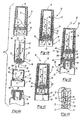
Figure 1 is an exploded, partially cross-sectioned view of one embodiment of the transfer set assembly of this invention; -
Figure 2A is an exploded cross-sectional view of the transfer set assembly shown inFigure 1 and a conventional medical vial; -
Figure 2B is a cross-sectional view of the cross-sectional view of the assembled transfer set; -
Figure 2C is a cross-sectional view similar toFigure 2B following retraction of the needle cannula; -
Figure 2D is an enlarged cross-sectional view ofFigure 2C ; -
Figure 2E is a cross-sectional view of the transfer set assembly shown inFigure 2C during installation of the transfer set on a conventional vial; -
Figure 3A is a side elevation of the transfer set assembled on a conventional vial; -
Figure 3B is a side cross-sectional view ofFigure 3A ; -
Figure 4A is a side elevation of the transfer set and container assembly following initial rotation of the closure; -
Figure 4B is a side cross-sectional view ofFigure 4A illustrating the piercing of the seal on the container; -
Figure 5A is a cross-sectional view of the transfer set and container assembly following further rotation of the closure, which drives the closure from the collar; -
Figure 5B is a side cross-sectional view following removal of the closure; -
Figure 5C is a cross-sectional view ofFigure 5B in the direction ofview arrows 5C; -
Figure 6 is a partially cross-sectioned side perspective view of the closure; -
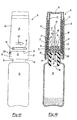
Figure 7 is a side view of the transfer set and a conventional intravenous infusion bag illustrating one use of the transfer set assembly of this invention; -
Figure 8 illustrates an example of a transferset designed; -
Figure 9 is a partial cross-sectional view of the example ofFigure 8 in a first position; -
Figure 10 is a cross-sectional view of the example ofFigure 9 ; and -
Figure 11 is a cross-sectional view of the example ofFigure 8 in a second position. - Referring now to
Figures 1 and2A which are exploded views of one embodiment of the transfer set assembly of this invention, the transfer setassembly 20 includes acollar 22, a needle cannula andholder assembly 24 and a closure orcap 26. Thecollar 22 includes a proximatetubular end portion 28, anintermediate portion 30 having an axial configuredopening 32 and a tubulardistal portion 34. As described above, the disclosed embodiment of the transfer set assembly of this invention is particularly, but not exclusively, adapted for attachment to aconventional vial 36 as shown for example inFigure 2A . A conventional vial has a reduceddiameter neck portion 38 and an elastomeric stopper or seal 40 which is received in theopen end 42 of the vial. Aconventional stopper 40 includes atubular portion 44 and aplanar end portion 46. As will be understood by those skilled in this art, stoppers for conventional vials are available in various configurations and are generally formed of synthetic or natural rubber. Conventional vials are formed of glass or plastic. The external diameter of thetubular portion 44 of the stopper is generally slightly greater than the internal diameter of theopening 42 of the vial, such that the stopper forms a tight interference fit providing an excellent seal for the vial. The proximatetubular end portion 28 is adapted to be received over theopen end 42 of the vial for securement thereto as described below. - The needle cannula and
holder assembly 24 includes aneedle cannula holder 48 having aproximate end portion 50 and a tubulardistal portion 52. Theneedle cannula 54 is securely retained in theproximate end portion 50 of theholder 24 and includes a firstproximate end portion 56 which extends axially beyond theproximate end portion 50 of the holder having asharp edge 58 for piercing theplanar end portion 46 of the stopper as described below. In the disclosed embodiment of the transfer set assembly adapted for transferring fluid between thevial 36 and an IV infusion bag described below, theneedle cannula 54 includes a seconddistal end portion 60 having asharp edge 64. - The closure or
cap 26 includes atubular body portion 66, a proximateopen end 68 and a closeddistal end 70. In the embodiment of the transfer set assembly ofFigures 1 through 6 , the closure further includes an inner cylindricaltubular portion 72 having afree end 74 which includes spiral camming surfaces 76 which mate with spiral camming surfaces 78 on the internal surface of the tubulardistal portion 52 of theneedle cannula holder 48 as described above. In an example which is illustrated inFigures 8 through 11 , the innertubular portion 72 is not used and the camming surfaces are relocated. In the example ofFigures 1 to 6 of theclosure 26, the innertubular portion 72 is integral with the closeddistal end 70 and is generally coaxially aligned with, but spaced from thetubular body portion 66 as shown. As will be understood, the term "tubular" as used herein is not intended to limit the shape of the tubular form which may be cylindrical, polygonal, etc. except where specifically described. -
Figure 2B illustrates the transfer set assembly following initial assembly of the components. As shown, theproximate end portion 50 of theneedle holder 48 is telescopically received in the tubulardistal portion 34 of thecollar 22 until the proximate end engages theintermediate portion 30 of the collar. Theneedle cannula holder 24 must be initially located in this position to receive theclosure 26 because of the interference of the spiral camming surfaces. As shown inFigure 2B , theopen end 68 of the closure is then telescopically disposed over the needle cannula andholder assembly 24, wherein the innertubular portion 72 is received within the tubulardistal portion 52 of the holder and the open end is then received over the tubulardistal portion 34 of the collar as shown. The needle cannula andholder assembly 24 is then repositioned upwardly or retracted as shown inFigure 2C until theinternal rib 80 at the free end of the tubulardistal portion 34 of the collar snaps into theannular groove 82 of the needle holder as best shown inFigure 2D . The interlock between therib 80 and thegroove 82 then temporarily holds the needle cannula and holder assembly in the position shown inFigure 2C . The transfer setassembly 20 is then ready for installation on the first container and shown inFigure 2E . - As stated above, the proximate
tubular end portion 28 of thecollar 22 is adapted for attachment to a sealed first container, which in the disclosed embodiment is aconventional vial 36 sealed with astopper 40. In this embodiment, thefree end 84 is permanently deformed, crimped or spun radially inward toward i or into theneck portion 38 of the vial as shown byarrow 86. During this installation, theintermediate portion 30 of the collar is pressed into theplanar end portion 46 of the resilient elastomeric stopper providing an excellent seal. In the most preferred embodiment, theintermediate portion 30 of the collar includes an annular relatively sharp projecting rib 88 which bites into theplanar end portion 46 of the resilient elastomeric stopper, further improving the seal and resisting relative rotation. As set forth above, however, the transfer set assembly of this invention may be utilized for transferring fluid between any first container and a second container and therefore the transfer set of this invention is not limited to the means of attaching the transfer set to the first container. - The components of the transfer set assembly excluding the
needle cannula 54 are preferably formed of polymers, most preferably clear polymers, which permit the healthcare worker to view the components of the transfer set assembly prior to and during use. - The preferred polymers selected for the components of the transfer set assembly of the invention will depend upon the particular application. The most preferred polymer for the collar can best be described by its properties. The polymer should be sufficiently malleable to permit radial deformation or crimping as described, yet sufficiently rigid to retain its shape following deformation. The polymer should also be sufficiently resistant to creep to maintain the seal between the transfer set assembly and the container following radial deformation. It has been found that a polymer having an elongation at yield between 5% and 10% and an elongation at break greater than 100%, combined with a flectual modulas of greater than 1900 MPa has superior performance. Where the transfer set assembly of this invention is used for sealed vials or other containers containing a pharmaceutical substance, the selected polymers should also be sterilizable and, in certain applications such as the transfer set assembly of this invention, the polymer is preferably relatively clear as set forth above and maintains its clarity under the stress of deformation or crimping. It has been found that certain composite polymers such as polymer alloys or composite polymers including melt blends or alloys and copolymers having polymers of different malleability and rigidity are preferred in such applications. That is, the collar of the transfer set of this invention is preferably formed of a polymer alloy, composite polymer or copolymer including a relatively rigid polymer and a tough relatively soft malleable copolymer. The most preferred polymer is a polymer alloy or melt blend including a polyamide or polycarbonate as the rigid polymer providing the strength and resistance to creep desired for this application. The relatively soft malleable copolymer may be selected from various polymers including polyesters and polyolefins; however, a polymer alloy including in a polymer carbonate or polyamide has been found particularly suitable for this application.
- As will be understood, various composite polymers including polymeric melt blends, alloys, composites and co-polymers are being developed on a rapidly increasing basis and therefore the material selected for the plastic collar and components of the transfer set of this invention is not limited to a specific polymer, provided the polymers have the desired physical properties described for the application. Suitable polymers for the plastic collar of the transfer set of this invention include EASTAR® MB polymers, which are melt blend and alloy polymers and EASTAR® thermoplastic polymers, which are neat polymers sold by Eastman Chemical Company of Kingsport, Tennessee and Eastman Chemical AG of Zug, Switzerland under the trade names "DA003, DN003" and "DN004". These materials are polymer melt blends, alloys and co-polymers of polycarbonate or polyamide and polyester. As used herein, the terms melt blends and alloys refer to polymeric compositions having two or more polymers of different physical properties or characteristics, such as the EASTAR® polymers of Eastman Chemical Company described above which include a polycarbonate or polyamide and a polyester. The polymer selected may also include fillers and other constituents which would be more accurately described as a composite although the base polymers may still be a polymeric melt blend or alloy. As used herein, the term composite is used in its broadest sense to include alloys or melt blends, composites and co-polymers. As will be understood, the manufacturer or supplier of the raw material will normally blend the polymers based upon the specifications of the customer. The polymers may be co-injected to form a polymeric melt blend, alloy or composite or formed by any other suitable processes. It is anticipated, however, that other polymers having the described physical characteristics may also be utilized for the plastic collar and the other components of the transfer set of this invention. In certain applications, it may also be desirable to coat at least the interior surfaces of the components of the transfer set with a thermoplastic elastomer. The thermoplastic elastomer coating may be applied as a film or by co-injection. The components set
assembly 20 may be formed by conventional injection molding processes. - Rotation of the
needle cannula holder 48 relative to thecollar 22 during axial movement of the holder is prevented byaxial ribs 35 on opposed sides of the collar which are received inaxial grooves 53 in the opposed side of theholder 48 as best shown inFigure 5C . These interlocking ribs and grooves also assure accurate orientation of theholder 48 in thecollar 22.Figures 3A and 3B illustrate thetransfer assembly 20 assembled on aconventional vial 36, as described above, ready for use. As stated above, the vial may, for example, contain a dry or powdered substance which will be reconstituted with a diluent or solvent depending upon the application. As best shown inFigure 3A , the projections orprotrusions 90 are visible through theslots 94 and the location of the projections in the slots indicate to the healthcare worker that the vial and transfer set assembly is now ready for use. In addition, various tamper evident means may be utilized with the transfer set assembly of this invention to indicate tampering. In the disclosed embodiment, a tamper evidentfrangible bridge portion 98 extends across theslot 94 to indicate the position of theprojection 90 prior to use. Tamperevident tape 100 bridges thebody portion 66 of theclosure 26 and the proximatetubular end portion 28 of the collar. As shown inFigure 2D , the needle cannula andholder assembly 24 is releasably retained in the tubulardistal portion 34 of the collar byradial rib 80 received inannular groove 82 as described above. In this position, the firstproximate end 54 of theneedle cannula 54 is spaced from theplanar end 46 of the stopper and the mating camming surfaces 76 and 78 on the innertubular portion 72 of the closure and the internal surface of the tubulardistal portion 52 of the needle cannula holder respectively are in engagement as shown. - The distal
tubular portion 34 of thecollar 22 includes projections orprotrusions 90 which are received inaxial slots 92 at the proximateopen end 68 of theclosure 26 as the closure is telescopically received over the tubulardistal portion 34 of the collar. Theaxial slots 92 communicate with transverselateral slots 94. As described below, theprojections 90 in thelateral slots 92 prevent removal of the closure prior to and during the initial rotation of theclosure 26 relative to thecollar 22. Thelateral slots 94 each communicate with angled or helical camming surfaces 96 which extend to theopen end 68 of the closure and which drive the closure from the collar as described below.Radial grooves 33 preferably are provided on the interior surface of the closure body portion which may be filled with silicone to improve sealing. - When the transfer set and vial assembly is ready for use, the healthcare worker rotates the
closure 26 relative to thevial 36 as shown byarrow 102, which drives the mating camming surfaces 76 and 78 together, driving the needle cannula andholder assembly 24 in the direction ofarrow 104. In the disclosed embodiment, the free end of the tubulardistal portion 34 of thecollar 22 includesaxial slots 81 which facilitate release of the holder by increasing its flexibility. Thesharp edge 58 of the needle cannula then pierces theplanar end portion 46 of the elastomeric stopper as shown inFigure 4 . Rotation of theneedle cannula holder 48 relative to thecollar 22 during axial movement of the holder is prevented byaxial ribs 35 on opposed sides of the collar which are received inaxial grooves 53 in the opposed sides of theholder 48. These interlocking ribs and grooves also assure accurate location of theholder 48 in thecollar 22. When the needle cannula and holder assembly is fully extended as shown inFigure 4 , the hook-shaped connectors 106 (see alsoFigure 2A ) are received throughopening 32 in the midportion of the collar and snap in place, locking the needle cannula and holder assembly as shown inFigure 4B . As shown inFigure 4A , rotation of the collar as described breaks the tamper evident bridgingportion 98 on thelateral slots 94 and the tamperevident tape 100 bridging theclosure 26 and the proximatetubular end portion 28 of the collar. As will be understood, various tamper evidence means may be utilized. Alternatively, for example, thebridge 98 may be replaced by a thin integral plastic web formed during molding of the cover. As best shown inFigure 2A , theopening 32 through theintermediate portion 30 of thecollar 22 is generally cone-shaped and the hook-shapedelements 106, which may be molded integral with theintermediate portion 50, provide guidance for the hook-shaped elements and secure retention of the needle cannula and holder assembly. - Continued rotation of the
closure 26 in the direction ofarrow 102 inFigure 5 disposes theprojections 90 against the angled camming surfaces 96 which, as described above, are contiguous with thelateral slots 94, thereby driving theclosure 96 away from the proximatetubular end portion 28 of the collar, releasing the collar and providing clear indication to the healthcare worker that the transfer set and vial assembly is ready for use to transfer fluids from the vial to a second container. Theclosure 26 is then removed as shown inFigure 5B , exposing thedistal end portion 60 of the needle cannula. Where the transfer set assembly is adapted for transfer of fluids between the vial and a second container having a tubular port, as shown for example inFigure 7 and described below, the tubulardistal portion 52 preferably extends beyond thesharp edge 64 of thedistal end portion 60 of the needle cannula as seen inFigure 5 . As shown inFigures 1 and7 ,axial slots 108 may be provided in the tubular distal portion of theneedle cannula holder 24 to permit the healthcare worker to clearly see the location of the needle cannula for installation. -
Figure 7 illustrates one use of the transfer setassembly 20 of this invention for transferring fluid between avial 36 and anIV infusion bag 110. As shown, theaxial slot 108 in the tubular distal portion permits the healthcare worker to easily view thedistal end portion 60 of the needle (not shown) inFigure 7 and the tubulardistal portion 52 of the needle holder guides thetubular port 112 of the infusion bag to pierce the seal in the end of thetubular port 112. A conventional infusion bag includes twotubular ports IV infusion bag 110 is first transferred to the powdered medicament in the vial with the infusion bag located above the vial. Once the transfer set is connected to thetubular port 112 as described, fluid communication is provided through the needle cannula and the infusion bag. The liquid is transferred to the vial by squeezing the IV infusion bag, which transfers fluid from the infusion bag to the vial, reconstituting the drug in the vial. The infusion bag is then reversed as shown inFigure 7 and the reconstituted drug is then transferred from the vial to the infusion bag. This method of transferring fluid from a vial or other container to an IV infusion bag is well known in the art and therefore no further description is required. -
Figures 8 through 11 illustrate an example of a transferset assembly. There are substantial similarities between this example and that discussed above and as shown inFigures 1 through 6 . Therefore, similar numbering with an increase by 200 have been used in the drawings to avoid the need for duplicate descriptions. - The
closure 226 of this example does not include the innertubular portion 72 that was used in the previous example. Instead, theclosure 226 includes camming surfaces 276 formed on the inside or interior surface of theclosure 226. Additionally, the camming surfaces 278 are relocated relative to thesurfaces 78 in the previous example. In this assembly, the camming surfaces 278 are positioned on the outside surface of theneedle holder portion 224. The camming surfaces 276 cooperate with the camming surfaces 278 in the same manner as the camming surfaces described in the previous example. Otherwise, the operation of the example shown inFigures 8 through 11 preferably is identical to the example ofFigures 1 through 6 . The rotation of theclosure 226 causes movement of theneedle holder portion 224 to secure the needle holder portion in place and to make fluid communication through theneedle 256 possible to transfer fluid into or out of the container to which the assembly is attached in the same manner as described above. - The location of the camming surfaces in the example of
Figures 8 through 11 is advantages from a manufacturing standpoint. There is no need to include the innertubular portion 72 and, therefore, less material is required and the mold used in a molding process is not as complex. Given this description, those skilled in the art will realize which of the disclosed embodiments, or other modified arrangements, will best suit their needs for a particular circumstance. - As will now be understood, the transfer set assembly of this invention is simple to use and provides a substantially foolproof operation. The transfer set of this invention may be utilized with any sealed container, including but not limited to conventional vials, and may be utilized to transfer fluids between the sealed container and any conventional container including, for example, an IV infusion bag. The transfer set of this invention assures sterile conditions of the transfer set and the medicament within the sealed container during filling of the container and use of the container assembly. Further, the transfer set assembly of this invention protects the healthcare worker and provides a positive indication of the piercing of the seal on the vial or other container and release of the closure. As will also be understood, various modifications may be made to the disclosed transfer set of this invention within the scope of the appended claims. For example, the
collar 22 may be modified to accommodate other containers and various materials may be utilized for the components of the transfer set assembly of this invention.
Claims (9)
- A transfer set assembly for transferring fluids between a first container (36) having a sealed open end (42) and a second container (110) under sterile conditions, said transfer set assembly (20) comprising:a collar (22), a needle cannula and holder assembly (24) and a closure the needle cannula and holder assembly (24) comprising a needle cannula holder (48) and a needle cannula (54);said collar (22) having a proximate tubular end portion (28) adapted to be received over said sealed open end of said first container (36) for securement thereto, an intermediate portion (30) having an axial opening (32) therethrough and a distal tubular portion (34);said needle cannula holder (48) having a proximate end portion (50) telescopically received in said distal tubular portion (34) of said collar (22) and a tubular distal end portion (52) and said tubular distal end portion having a first angled camming surface (78);said needle cannula (54) supported in said needle cannula holder (48) having a free proximate end portion (56) projecting axially beyond said proximate end portion (50) of said needle cannula holder (48);said closure (26) having a tubular body portion (66) surrounding said needle cannula holder (48) and said distal tubular portion (34) of said collar (22), a closed distal end portion (70) and an inner tubular portion (72) generally coaxially aligned with said tubular body portion (66) having a second angled camming surface(76) engaging said first angled camming surface (78) of said needle cannula holder (48);whereby, rotation of said closure (26) relative to the collar (22) and the needle cannula holder (48) drives said needle cannula and holder assembly (24) axially to pierce said sealed open end (42) of said first container (36),characterized in thatone of said closure tubular body portion (66) and said collar distal tubular portion (34) includes a third angled camming surface (96) and the other of said closure tubular body portion and said collar distal tubular portion includes a projection (90) engaging said angled camming surface, whereby rotation of said closure (26) relative to said collar (22) drives said closure away from said collar.
- The transfer set assembly defined in Claim 1, wherein said inner tubular portion (72) of said closure (26) has a free end (74) having the second angled camming surface in form of at least two spiral camming surfaces (76) engaging the first angled camming surface in form of spiral camming surfaces (78) on said needle cannula holder (48).
- The transfer set assembly defined in Claim 2, wherein said inner tubular portion (72) of said closure (26) is telescopically received within said tubular distal portion (52) of said needle cannula holder (48) and said spiral camming surfaces (78) on said needle cannula holder (48) are located on an internal surface of said tubular distal portion (52) of said holder.
- The transfer set assembly defined in Claim 3, wherein said inner tubular portion (72) of said closure (26) is integral with said closed distal end (70) and said free end (74) of said inner tubular portion (72) is spaced from said closed distal end (70) of said closure.
- The transfer set assembly defined in Claim 1, wherein said distal tubular portion (34) of said collar (22) and said needle cannula holder (48) have an interlocking axial rib and groove (35,53) which permit telescopic movement of said needle cannula holder within said distal tubular portion of said collar while preventing rotational movement of said needle cannula holder relative to said collar.
- The transfer set assembly defined in Claim 1, wherein said projection (90) is on said collar (22) distal tubular portion (34) and said third angled camming surface (96) is on an internal surface of said closure tubular body portion (66).
- The transfer set assembly defined in Claim 6, wherein said closure tubular body portion (66) includes a laterally extending slot (94) adjacent said third angled camming surface (96), said projection (90) on said collar (22) initially received in said lateral slot in said closure tubular body portion, whereby rotation of said closure (26) relative to said collar (22) first drives said needle cannula and holder assembly (24) axially to pierce said sealed open end (42) of said first container (36) as said projection rotates in said later slot, then driving said closure away from said collar as said projection is received against said angled camming surface (96) on said closure body portion (66).
- The transfer set assembly defined in Claim 1, wherein said closure (26) is releasably retained to said collar (22) by a frangible connector (100), whereby rotation of said closure relative to said collar brakes said frangible connector, releasing said closure from said collar.
- The transfer set assembly defined in Claim 1, wherein said proximate end portion (50) of said needle cannula holder (48) has an axial opening receiving and retaining said needle cannula (54), said holder proximate end portion having a plurality of hook-shaped connectors (106) which are received in said axial opening (32) in said intermediate portion (30) of said collar retaining said needle cannula and holder assembly to said collar after said needle cannula pierces said sealed opened end of said first container.
Priority Applications (1)
| Application Number | Priority Date | Filing Date | Title |
|---|---|---|---|
| EP20080100572 EP1952791B1 (en) | 1999-10-20 | 2000-10-04 | Transfer set for vials and medical containers |
Applications Claiming Priority (2)
| Application Number | Priority Date | Filing Date | Title |
|---|---|---|---|
| US09/420,998 US6209738B1 (en) | 1998-04-20 | 1999-10-20 | Transfer set for vials and medical containers |
| US420998 | 1999-10-20 |
Related Child Applications (1)
| Application Number | Title | Priority Date | Filing Date |
|---|---|---|---|
| EP20080100572 Division EP1952791B1 (en) | 1999-10-20 | 2000-10-04 | Transfer set for vials and medical containers |
Publications (3)
| Publication Number | Publication Date |
|---|---|
| EP1093784A2 EP1093784A2 (en) | 2001-04-25 |
| EP1093784A3 EP1093784A3 (en) | 2003-01-15 |
| EP1093784B1 true EP1093784B1 (en) | 2008-05-28 |
Family
ID=23668766
Family Applications (2)
| Application Number | Title | Priority Date | Filing Date |
|---|---|---|---|
| EP20000121656 Expired - Lifetime EP1093784B1 (en) | 1999-10-20 | 2000-10-04 | Transfer set for vials and medical containers |
| EP20080100572 Expired - Lifetime EP1952791B1 (en) | 1999-10-20 | 2000-10-04 | Transfer set for vials and medical containers |
Family Applications After (1)
| Application Number | Title | Priority Date | Filing Date |
|---|---|---|---|
| EP20080100572 Expired - Lifetime EP1952791B1 (en) | 1999-10-20 | 2000-10-04 | Transfer set for vials and medical containers |
Country Status (7)
| Country | Link |
|---|---|
| US (2) | US6209738B1 (en) |
| EP (2) | EP1093784B1 (en) |
| JP (1) | JP4884584B2 (en) |
| AT (2) | ATE396688T1 (en) |
| AU (1) | AU782339B2 (en) |
| DE (2) | DE60043520D1 (en) |
| ES (2) | ES2336971T3 (en) |
Cited By (2)
| Publication number | Priority date | Publication date | Assignee | Title |
|---|---|---|---|---|
| US11505776B2 (en) | 2019-12-17 | 2022-11-22 | Oribiotech Ltd | Connector |
| RU2803517C2 (en) * | 2019-06-24 | 2023-09-14 | Фриксос ПРОДРОМУ | Childproof dispenser and child lock |
Families Citing this family (184)
| Publication number | Priority date | Publication date | Assignee | Title |
|---|---|---|---|---|
| US5613291A (en) * | 1995-01-25 | 1997-03-25 | Becton, Dickinson And Company | Method for providing a sterility seal in a medicinal storage bottle |
| US6681946B1 (en) * | 1998-02-26 | 2004-01-27 | Becton, Dickinson And Company | Resealable medical transfer set |
| US6378714B1 (en) * | 1998-04-20 | 2002-04-30 | Becton Dickinson And Company | Transferset for vials and other medical containers |
| US6957745B2 (en) * | 1998-04-20 | 2005-10-25 | Becton, Dickinson And Company | Transfer set |
| US6726672B1 (en) * | 1998-09-28 | 2004-04-27 | Icu Medical, Inc. | Intravenous drug access system |
| FR2802183B1 (en) * | 1999-12-10 | 2002-02-22 | Biodome | METHOD FOR MANUFACTURING A CONNECTION DEVICE BETWEEN A CONTAINER AND A CONTAINER, CORRESPONDING CONNECTION DEVICE AND READY-TO-USE ASSEMBLY COMPRISING SUCH A DEVICE |
| US6607508B2 (en) | 2000-04-27 | 2003-08-19 | Invivotech, Inc. | Vial injector device |
| CA2397688C (en) * | 2001-08-17 | 2012-01-17 | Becton Dickinson And Company | Liquid specimen collection system |
| DE10142450C1 (en) * | 2001-08-31 | 2003-06-18 | Aventis Behring Gmbh | Device for bringing components together under sterile conditions |
| WO2003072162A2 (en) * | 2002-02-25 | 2003-09-04 | Mitali Dutt | Probe-activated medicament injector device |
| US8562583B2 (en) | 2002-03-26 | 2013-10-22 | Carmel Pharma Ab | Method and assembly for fluid transfer and drug containment in an infusion system |
| US7867215B2 (en) * | 2002-04-17 | 2011-01-11 | Carmel Pharma Ab | Method and device for fluid transfer in an infusion system |
| SE523001C2 (en) * | 2002-07-09 | 2004-03-23 | Carmel Pharma Ab | Coupling component for transmitting medical substances, comprises connecting mechanism for releasable connection to second coupling component having further channel for creating coupling, where connecting mechanism is thread |
| US7544191B2 (en) * | 2002-10-22 | 2009-06-09 | Baxter International Inc. | Formed, filled, sealed solution container, port and method for establishing flow between the container and an administration set |
| US7507226B2 (en) * | 2002-10-22 | 2009-03-24 | Baxter International Inc. | Access port with safety tab and fluid container employing same |
| US7942861B2 (en) | 2002-10-22 | 2011-05-17 | Baxter International Inc. | Fluid container with access port and safety cap |
| US7491182B2 (en) * | 2002-11-15 | 2009-02-17 | Hill-Rom Services, Inc. | High frequency chest wall oscillation apparatus having plurality of modes |
| CA2513705A1 (en) * | 2003-01-21 | 2004-08-05 | Carmel Pharma Ab | A needle for penetrating a membrane |
| DE10340585A1 (en) * | 2003-09-03 | 2005-04-07 | Tecpharma Licensing Ag | Administration device with multi-chamber ampoule and mixing stop |
| EP3108911A1 (en) * | 2003-10-30 | 2016-12-28 | Teva Medical Ltd. | Safety drug handling device |
| EP1707500A1 (en) * | 2004-01-19 | 2006-10-04 | Taisei Kako Co., Ltd. | Mixing container set in use |
| DE102004005435B3 (en) * | 2004-02-04 | 2005-09-15 | Haindl, Hans, Dr. | Medical transfer device |
| GB2414402B (en) * | 2004-05-28 | 2009-04-22 | Cilag Ag Int | Injection device |
| GB2414775B (en) | 2004-05-28 | 2008-05-21 | Cilag Ag Int | Releasable coupling and injection device |
| GB2414400B (en) | 2004-05-28 | 2009-01-14 | Cilag Ag Int | Injection device |
| SE0401408D0 (en) * | 2004-06-02 | 2004-06-02 | Astrazeneca Ab | Diameter measuring device |
| JP5100378B2 (en) * | 2004-07-07 | 2012-12-19 | ロナルド アラン グリーンベルグ | Hand tool assembly for skin polishing. |
| US8048212B2 (en) | 2004-09-21 | 2011-11-01 | Cummins Filtration Ip, Inc. | Inertial gas-liquid separator with valve and variable flow actuator |
| US20060184103A1 (en) * | 2005-02-17 | 2006-08-17 | West Pharmaceutical Services, Inc. | Syringe safety device |
| GB2427826B (en) | 2005-04-06 | 2010-08-25 | Cilag Ag Int | Injection device comprising a locking mechanism associated with integrally formed biasing means |
| GB2425062B (en) | 2005-04-06 | 2010-07-21 | Cilag Ag Int | Injection device |
| GB2424836B (en) * | 2005-04-06 | 2010-09-22 | Cilag Ag Int | Injection device (bayonet cap removal) |
| CA2606638C (en) * | 2005-05-06 | 2014-07-08 | Instrumentation Laboratory Company | Telescoping closed-tube sampling assembly |
| EP1759729B1 (en) | 2005-08-30 | 2009-12-23 | Cilag GmbH International | Needle assembly for a prefilled syringe system |
| US20110098656A1 (en) | 2005-09-27 | 2011-04-28 | Burnell Rosie L | Auto-injection device with needle protecting cap having outer and inner sleeves |
| EP1957028B1 (en) * | 2005-10-30 | 2017-06-07 | Medimop Medical Projects Ltd. | Needleless additive control valve |
| EP1951344B1 (en) * | 2005-11-07 | 2014-05-28 | Industrie Borla SpA | Vented safe handling vial adapter |
| DE102005057547A1 (en) * | 2005-11-30 | 2007-05-31 | Clinico Gmbh | Device for transferring liquids, suspensions, and solid materials from first receptacle into second receptacle, has fastening device formed by conventional receptacle closure |
| US20070202186A1 (en) | 2006-02-22 | 2007-08-30 | Iscience Interventional Corporation | Apparatus and formulations for suprachoroidal drug delivery |
| ES2425579T3 (en) | 2006-05-25 | 2013-10-16 | Bayer Healthcare, Llc | Reconstitution device |
| GB2438590B (en) * | 2006-06-01 | 2011-02-09 | Cilag Gmbh Int | Injection device |
| GB2438591B (en) * | 2006-06-01 | 2011-07-13 | Cilag Gmbh Int | Injection device |
| GB2438593B (en) | 2006-06-01 | 2011-03-30 | Cilag Gmbh Int | Injection device (cap removal feature) |
| WO2008020447A1 (en) * | 2006-08-18 | 2008-02-21 | Medingo Ltd. | Methods and devices for delivering fluid to a reservoir of a fluid delivery device |
| US7670326B2 (en) * | 2006-09-25 | 2010-03-02 | Teva Medical Ltd.. | Syringe adapter element in drug mixing system |
| DK2071917T3 (en) * | 2006-09-29 | 2013-03-04 | Infa Sa | Packaging system for pharmaceutical compositions and kits for intravenous administration |
| ITMI20061881A1 (en) * | 2006-09-29 | 2008-03-30 | Novachem S A | PHARMACEUTICAL COMPOSITION PACKAGING SYSTEM INCLUDING ACTIVE PRINCIPLES ADMINISTRATIVE FOR ENDOVENOUS ROUTE |
| CA2564061A1 (en) * | 2006-10-16 | 2008-04-16 | Duoject Medical Systems Inc. | Reconstitution system for mixing the contents of a vial containing a first substance with a second substance stored in a cartridge |
| EP2125572A2 (en) * | 2006-11-29 | 2009-12-02 | West Pharmaceutical Services, Inc. | Syringe cartridge system |
| GB0701326D0 (en) * | 2007-01-24 | 2007-03-07 | Obrist Closures Switzerland | A perforable closure |
| US7942860B2 (en) | 2007-03-16 | 2011-05-17 | Carmel Pharma Ab | Piercing member protection device |
| US7975733B2 (en) * | 2007-05-08 | 2011-07-12 | Carmel Pharma Ab | Fluid transfer device |
| EP1995182A1 (en) * | 2007-05-25 | 2008-11-26 | F.Hoffmann-La Roche Ag | A sealing cap for a fluid container and a blood collection device |
| US8622985B2 (en) * | 2007-06-13 | 2014-01-07 | Carmel Pharma Ab | Arrangement for use with a medical device |
| US8029747B2 (en) | 2007-06-13 | 2011-10-04 | Carmel Pharma Ab | Pressure equalizing device, receptacle and method |
| US8657803B2 (en) | 2007-06-13 | 2014-02-25 | Carmel Pharma Ab | Device for providing fluid to a receptacle |
| WO2009026443A2 (en) | 2007-08-21 | 2009-02-26 | Gilero, Llc | Vial access and injection system |
| US10398834B2 (en) | 2007-08-30 | 2019-09-03 | Carmel Pharma Ab | Device, sealing member and fluid container |
| WO2009035383A1 (en) * | 2007-09-11 | 2009-03-19 | Carmel Pharma Ab | Piercing member protection device |
| US8287513B2 (en) * | 2007-09-11 | 2012-10-16 | Carmel Pharma Ab | Piercing member protection device |
| DE102007046951B3 (en) * | 2007-10-01 | 2009-02-26 | B. Braun Melsungen Ag | Device for introducing a medicament into an infusion container |
| US20090105684A1 (en) * | 2007-10-23 | 2009-04-23 | Baxter International Inc. | Medication port for medical fluid container |
| EP4088772A1 (en) * | 2008-01-28 | 2022-11-16 | Implantica Patent Ltd. | A drainage device |
| AT505616B1 (en) | 2008-02-07 | 2009-03-15 | Pickhard Brigitte | INJECTION sYRINGE |
| CA2720233A1 (en) * | 2008-04-01 | 2009-12-03 | Yukon Medical, Llc | Dual container fluid transfer device |
| GB2461086B (en) | 2008-06-19 | 2012-12-05 | Cilag Gmbh Int | Injection device |
| GB2461084B (en) | 2008-06-19 | 2012-09-26 | Cilag Gmbh Int | Fluid transfer assembly |
| GB2461088B (en) * | 2008-06-19 | 2012-09-26 | Cilag Gmbh Int | Injection device |
| GB2461087B (en) * | 2008-06-19 | 2012-09-26 | Cilag Gmbh Int | Injection device |
| GB2461085B (en) * | 2008-06-19 | 2012-08-29 | Cilag Gmbh Int | Injection device |
| GB2461089B (en) | 2008-06-19 | 2012-09-19 | Cilag Gmbh Int | Injection device |
| US8075550B2 (en) * | 2008-07-01 | 2011-12-13 | Carmel Pharma Ab | Piercing member protection device |
| US8141601B2 (en) | 2008-10-02 | 2012-03-27 | Roche Diagnostics Operations, Inc. | Manual filling aid with push button fill |
| CA2780712A1 (en) * | 2008-11-12 | 2010-05-20 | British Columbia Cancer Agency Branch | Vial handling and injection safety systems and connectors |
| US8790330B2 (en) * | 2008-12-15 | 2014-07-29 | Carmel Pharma Ab | Connection arrangement and method for connecting a medical device to the improved connection arrangement |
| US8523838B2 (en) * | 2008-12-15 | 2013-09-03 | Carmel Pharma Ab | Connector device |
| US8864725B2 (en) | 2009-03-17 | 2014-10-21 | Baxter Corporation Englewood | Hazardous drug handling system, apparatus and method |
| AU2010236426B2 (en) | 2009-04-14 | 2013-08-29 | Yukon Medical, Llc | Fluid transfer device |
| TW201109057A (en) * | 2009-06-02 | 2011-03-16 | Sanofi Aventis Deutschland | Medicated module with bypass and needle guard |
| TWI519330B (en) * | 2009-06-02 | 2016-02-01 | 賽諾菲阿凡提斯德意志有限公司 | Medicated module with user selection |
| IL201323A0 (en) | 2009-10-01 | 2010-05-31 | Medimop Medical Projects Ltd | Fluid transfer device for assembling a vial with pre-attached female connector |
| US9662271B2 (en) | 2009-10-23 | 2017-05-30 | Amgen Inc. | Vial adapter and system |
| IL202070A0 (en) | 2009-11-12 | 2010-06-16 | Medimop Medical Projects Ltd | Inline liquid drug medical device |
| USD637713S1 (en) | 2009-11-20 | 2011-05-10 | Carmel Pharma Ab | Medical device adaptor |
| US8480646B2 (en) * | 2009-11-20 | 2013-07-09 | Carmel Pharma Ab | Medical device connector |
| FR2952813B1 (en) * | 2009-11-26 | 2012-05-18 | Perouse Medical | DEVICE FOR CONNECTING TWO CONTAINERS, INTENDED PARTICULARLY FOR MEDICAL USE |
| CN102869397B (en) * | 2010-01-15 | 2015-10-14 | 拜耳医药保健有限公司 | Device |
| CN102711712B (en) | 2010-02-24 | 2014-08-13 | 麦迪麦珀医疗工程有限公司 | Fluid transfer assembly with venting arrangement |
| JP5709905B2 (en) | 2010-02-24 | 2015-04-30 | メディモップ・メディカル・プロジェクツ・リミテッド | Liquid transfer device including vial adapter with vent |
| US9408746B2 (en) | 2010-03-31 | 2016-08-09 | Ocuject, Llc | Device and method for intraocular drug delivery |
| US9320647B2 (en) | 2010-03-31 | 2016-04-26 | Ocuject, Llc | Device and method for intraocular drug delivery |
| EP2371342A1 (en) * | 2010-04-01 | 2011-10-05 | Siemens Healthcare Diagnostics Products GmbH | Device for storing and metering a solution |
| US9168203B2 (en) | 2010-05-21 | 2015-10-27 | Carmel Pharma Ab | Connectors for fluid containers |
| US8162013B2 (en) | 2010-05-21 | 2012-04-24 | Tobias Rosenquist | Connectors for fluid containers |
| USD655017S1 (en) | 2010-06-17 | 2012-02-28 | Yukon Medical, Llc | Shroud |
| BR112013004191B1 (en) | 2010-08-25 | 2021-02-02 | Baxalta GmbH | set to facilitate user reconstitution |
| US8734420B2 (en) | 2010-08-25 | 2014-05-27 | Baxter International Inc. | Packaging assembly to prevent premature activation |
| JP6118255B2 (en) * | 2010-11-01 | 2017-04-19 | ジーイー・ヘルスケア・リミテッド | Puncture and filling device |
| IL209290A0 (en) | 2010-11-14 | 2011-01-31 | Medimop Medical Projects Ltd | Inline liquid drug medical device having rotary flow control member |
| EP2646087B1 (en) * | 2010-11-29 | 2017-08-09 | Sanofi-Aventis Deutschland GmbH | Medicated module with automatic reservoir engagement |
| WO2012072563A1 (en) * | 2010-11-29 | 2012-06-07 | Sanofi-Aventis Deutschland Gmbh | Medicated module with automatic reservoir engagement |
| US8783304B2 (en) * | 2010-12-03 | 2014-07-22 | Ini Power Systems, Inc. | Liquid containers and apparatus for use with power producing devices |
| WO2012092394A1 (en) | 2010-12-29 | 2012-07-05 | Cardinal Health 414, Llc | Closed vial fill system for aseptic dispensing |
| US9065095B2 (en) | 2011-01-05 | 2015-06-23 | Ini Power Systems, Inc. | Method and apparatus for enhancing power density of direct liquid fuel cells |
| EP2680807B1 (en) * | 2011-03-04 | 2016-08-10 | Duoject Medical Systems Inc. | Easy linking transfer system |
| WO2012135315A1 (en) | 2011-03-31 | 2012-10-04 | Amgen Inc. | Vial adapter and system |
| IL212420A0 (en) | 2011-04-17 | 2011-06-30 | Medimop Medical Projects Ltd | Liquid drug transfer assembly |
| US20130102772A1 (en) | 2011-07-15 | 2013-04-25 | Cardinal Health 414, Llc | Systems, methods and devices for producing, manufacturing and control of radiopharmaceuticals-full |
| US20130020727A1 (en) | 2011-07-15 | 2013-01-24 | Cardinal Health 414, Llc. | Modular cassette synthesis unit |
| USD681230S1 (en) | 2011-09-08 | 2013-04-30 | Yukon Medical, Llc | Shroud |
| IL215699A0 (en) | 2011-10-11 | 2011-12-29 | Medimop Medical Projects Ltd | Liquid drug reconstitution assemblage for use with iv bag and drug vial |
| EP2773309B1 (en) | 2011-10-31 | 2016-04-20 | GE Healthcare Limited | Pierce and fill device |
| WO2013099610A1 (en) * | 2011-12-28 | 2013-07-04 | テルモ株式会社 | Adaptor unit |
| US9468423B2 (en) | 2012-01-10 | 2016-10-18 | Becton, Dickinson And Company | Safety shield for fluid specimen container |
| JP6096678B2 (en) * | 2012-01-19 | 2017-03-15 | テルモ株式会社 | Adapter unit |
| SG192312A1 (en) | 2012-02-02 | 2013-08-30 | Becton Dickinson Holdings Pte Ltd | Adaptor for coupling to a medical container |
| SG192310A1 (en) | 2012-02-02 | 2013-08-30 | Becton Dickinson Holdings Pte Ltd | Adaptor for coupling to a medical container |
| IN2014DN06930A (en) | 2012-02-02 | 2015-04-10 | Becton Dickinson Holdings Pte Ltd | |
| USD720451S1 (en) | 2012-02-13 | 2014-12-30 | Medimop Medical Projects Ltd. | Liquid drug transfer assembly |
| USD737436S1 (en) | 2012-02-13 | 2015-08-25 | Medimop Medical Projects Ltd. | Liquid drug reconstitution assembly |
| JP5978320B2 (en) * | 2012-03-05 | 2016-08-24 | ベクトン・ディキンソン・アンド・カンパニーBecton, Dickinson And Company | Transfer set with floating needle for drug reconstitution |
| US9504603B2 (en) | 2012-04-02 | 2016-11-29 | Ocuject, Llc | Intraocular delivery devices and methods therefor |
| US9421129B2 (en) * | 2012-04-02 | 2016-08-23 | Ocuject, Llc | Intraocular delivery devices and methods therefor |
| IL219065A0 (en) | 2012-04-05 | 2012-07-31 | Medimop Medical Projects Ltd | Fluid transfer device with manual operated cartridge release arrangement |
| ES2687025T3 (en) * | 2012-04-09 | 2018-10-23 | Becton, Dickinson And Company | Safety device for drug vial |
| USD769444S1 (en) | 2012-06-28 | 2016-10-18 | Yukon Medical, Llc | Adapter device |
| CN102743292B (en) * | 2012-07-02 | 2014-07-23 | 重庆莱美药业股份有限公司 | Pushing device for short-process pushing pre-loading type medicine feeding instrument |
| CA2783251A1 (en) * | 2012-07-17 | 2014-01-17 | Duoject Medical Systems Inc. | Reconstitution device with tip cap |
| IL221634A0 (en) | 2012-08-26 | 2012-12-31 | Medimop Medical Projects Ltd | Universal drug vial adapter |
| IL221635A0 (en) | 2012-08-26 | 2012-12-31 | Medimop Medical Projects Ltd | Drug vial mixing and transfer device for use with iv bag and drug vial |
| BR112015005157B1 (en) | 2012-09-13 | 2020-12-08 | Medimop Medical Projects Ltd | telescopic female drug bottle adapter |
| US20150217058A1 (en) | 2012-09-24 | 2015-08-06 | Enable Injections, Llc | Medical vial and injector assemblies and methods of use |
| USD734868S1 (en) | 2012-11-27 | 2015-07-21 | Medimop Medical Projects Ltd. | Drug vial adapter with downwardly depending stopper |
| JP5689901B2 (en) * | 2013-01-24 | 2015-03-25 | カルメル ファルマ アクチボラゲット | Puncture member protection device |
| IL225734A0 (en) | 2013-04-14 | 2013-09-30 | Medimop Medical Projects Ltd | Ready-to-use drug vial assemblages including drug vial and drug vial closure having fluid transfer member, and drug vial closure therefor |
| WO2014179698A2 (en) | 2013-05-03 | 2014-11-06 | Clearside Biomedical, Inc. | Apparatus and methods for ocular injection |
| DK2983745T3 (en) | 2013-05-10 | 2018-10-22 | West Pharma Services Il Ltd | Medical devices comprising ampoule adapter with interconnected module for dry drug |
| GB2515039B (en) | 2013-06-11 | 2015-05-27 | Cilag Gmbh Int | Injection Device |
| GB2515038A (en) | 2013-06-11 | 2014-12-17 | Cilag Gmbh Int | Injection device |
| GB2515032A (en) | 2013-06-11 | 2014-12-17 | Cilag Gmbh Int | Guide for an injection device |
| GB2517896B (en) | 2013-06-11 | 2015-07-08 | Cilag Gmbh Int | Injection device |
| HUE043627T2 (en) | 2013-06-18 | 2019-09-30 | Enable Injections Inc | Vial transfer and injection apparatus |
| JP1526207S (en) | 2013-08-05 | 2015-06-15 | ||
| USD765837S1 (en) | 2013-08-07 | 2016-09-06 | Medimop Medical Projects Ltd. | Liquid transfer device with integral vial adapter |
| US10688295B2 (en) | 2013-08-07 | 2020-06-23 | West Pharma. Services IL, Ltd. | Liquid transfer devices for use with infusion liquid containers |
| USD767124S1 (en) | 2013-08-07 | 2016-09-20 | Medimop Medical Projects Ltd. | Liquid transfer device with integral vial adapter |
| US20170056601A1 (en) * | 2014-03-11 | 2017-03-02 | Nipro Corporation | Needle assembly |
| USD794183S1 (en) | 2014-03-19 | 2017-08-08 | Medimop Medical Projects Ltd. | Dual ended liquid transfer spike |
| DE102014008610A1 (en) * | 2014-06-06 | 2015-12-17 | Kocher-Plastik Maschinenbau Gmbh | dispenser |
| EP3193812B1 (en) | 2014-08-26 | 2018-06-27 | Muffin Incorporated | Multi-cell sealed container |
| USD757933S1 (en) | 2014-09-11 | 2016-05-31 | Medimop Medical Projects Ltd. | Dual vial adapter assemblage |
| US10285907B2 (en) | 2015-01-05 | 2019-05-14 | West Pharma. Services IL, Ltd. | Dual vial adapter assemblages with quick release drug vial adapter for ensuring correct usage |
| DE102015201288B4 (en) | 2015-01-26 | 2017-01-05 | Bayer Pharma AG | Hollow-needle assembly |
| DE102015201275A1 (en) * | 2015-01-26 | 2016-07-28 | Bayer Pharma AG | Device for transferring a liquid between a storage container and at least one further use container |
| EP3067037B1 (en) * | 2015-03-09 | 2017-10-04 | Epsilon Elektronik Sanayi ve Ticaret A.S. | A safety medical transfer device |
| EA201890069A1 (en) * | 2015-06-16 | 2018-06-29 | Бёрингер Ингельхайм Ветмедика Гмбх | SYSTEM OF CAPACITIES AND THEIR CONNECTIONS |
| MX2017016558A (en) | 2015-06-16 | 2018-05-11 | Boehringer Ingelheim Vetmedica Gmbh | Connecting and container system. |
| US10357429B2 (en) | 2015-07-16 | 2019-07-23 | West Pharma. Services IL, Ltd. | Liquid drug transfer devices for secure telescopic snap fit on injection vials |
| USD801522S1 (en) | 2015-11-09 | 2017-10-31 | Medimop Medical Projects Ltd. | Fluid transfer assembly |
| WO2017090042A1 (en) | 2015-11-25 | 2017-06-01 | Medimop Medical Projects Ltd | Dual vial adapter assemblage including drug vial adapter with self-sealing access valve |
| US10022531B2 (en) | 2016-01-21 | 2018-07-17 | Teva Medical Ltd. | Luer lock adaptor |
| US11648179B2 (en) | 2016-05-16 | 2023-05-16 | Haemonetics Corporation | Sealer-less plasma bottle and top for same |
| US11559464B2 (en) | 2016-05-16 | 2023-01-24 | Haemonetics Corporation | Sealer-less plasma bottle and top for same |
| IL245803A0 (en) | 2016-05-24 | 2016-08-31 | West Pharma Services Il Ltd | Dual vial adapter assemblages including vented drug vial adapter and vented liquid vial adapter |
| IL245800A0 (en) | 2016-05-24 | 2016-08-31 | West Pharma Services Il Ltd | Dual vial adapter assemblages including identical twin vial adapters |
| IL246073A0 (en) | 2016-06-06 | 2016-08-31 | West Pharma Services Il Ltd | Fluid transfer devices for use with drug pump cartridge having slidable driving plunger |
| IL247376A0 (en) | 2016-08-21 | 2016-12-29 | Medimop Medical Projects Ltd | Syringe assembly |
| USD832430S1 (en) | 2016-11-15 | 2018-10-30 | West Pharma. Services IL, Ltd. | Dual vial adapter assemblage |
| IL249408A0 (en) | 2016-12-06 | 2017-03-30 | Medimop Medical Projects Ltd | Liquid transfer device for use with infusion liquid container and pincers-like hand tool for use therewith for releasing intact drug vial therefrom |
| IL251458A0 (en) | 2017-03-29 | 2017-06-29 | Medimop Medical Projects Ltd | User actuated liquid drug transfer devices for use in ready-to-use (rtu) liquid drug transfer assemblages |
| IL254802A0 (en) | 2017-09-29 | 2017-12-31 | Medimop Medical Projects Ltd | Dual vial adapter assemblages with twin vented female vial adapters |
| US11224555B2 (en) | 2018-04-23 | 2022-01-18 | Hospira, Inc. | Access and vapor containment system for a drug vial and method of making and using same |
| USD903864S1 (en) | 2018-06-20 | 2020-12-01 | West Pharma. Services IL, Ltd. | Medication mixing apparatus |
| JP1630477S (en) | 2018-07-06 | 2019-05-07 | ||
| JP2022501140A (en) * | 2018-09-27 | 2022-01-06 | エスエイチエル・メディカル・アーゲー | Equipment for aerosol dispensers, aerosol dispensers and methods |
| USD923812S1 (en) | 2019-01-16 | 2021-06-29 | West Pharma. Services IL, Ltd. | Medication mixing apparatus |
| JP1648075S (en) | 2019-01-17 | 2019-12-16 | ||
| EP3917486B1 (en) | 2019-01-31 | 2023-03-08 | West Pharma. Services IL, Ltd | Liquid transfer device |
| US11484470B2 (en) | 2019-04-30 | 2022-11-01 | West Pharma. Services IL, Ltd. | Liquid transfer device with dual lumen IV spike |
| CN110054134A (en) * | 2019-05-15 | 2019-07-26 | 四川大学华西医院 | A kind of disposable ampoule disinfection opener |
| US20220219842A1 (en) * | 2020-02-06 | 2022-07-14 | Thorne Intellectual Property Holdings, Llc | Closed convenience kits for sterilized medicine preparation |
| US11904150B2 (en) | 2020-05-12 | 2024-02-20 | Becton, Dickinson And Company | Hypodermic safety needle |
| CN111477374A (en) * | 2020-05-29 | 2020-07-31 | 成都纽瑞特医疗科技股份有限公司 | Container and method for closed operation of radioactive nuclide |
| USD956958S1 (en) | 2020-07-13 | 2022-07-05 | West Pharma. Services IL, Ltd. | Liquid transfer device |
Family Cites Families (167)
| Publication number | Priority date | Publication date | Assignee | Title |
|---|---|---|---|---|
| US37221A (en) | 1862-12-23 | Improved can or bottle stopper | ||
| US659519A (en) | 1900-06-28 | 1900-10-09 | Edgar H Finfrock | Toe-cap for boots or shoes. |
| US2342215A (en) | 1942-08-03 | 1944-02-22 | Harold N Perelson | Dispensing and sealing stopper |
| US2388634A (en) | 1944-12-07 | 1945-11-06 | Ace Glass Inc | Container for aseptic filling and dispensing of sterile liquids |
| US2607503A (en) | 1946-03-04 | 1952-08-19 | Mid West Bottle Cap Co | Bottle closure |
| US2524365A (en) | 1947-12-12 | 1950-10-03 | Arthur E Smith | Closure |
| US2653609A (en) | 1950-08-26 | 1953-09-29 | Arthur E Smith | Container closure |
| US2659370A (en) | 1950-08-26 | 1953-11-17 | Arthur E Smith | Closure |
| US2667986A (en) | 1951-12-22 | 1954-02-02 | Harold N Perelson | Self-sealing dispensing device |
| US3033202A (en) | 1955-10-07 | 1962-05-08 | Baxter Laboratories Inc | Parenteral solution equipment and method of using same |
| US2953132A (en) | 1955-10-27 | 1960-09-20 | Baxter Laboratories Inc | Parenteral solution equipment |
| US3164303A (en) | 1961-12-04 | 1965-01-05 | Semco Res Inc | Storage and mixing cartridge |
| US3206080A (en) | 1962-07-23 | 1965-09-14 | Abbott Lab | Dispensing assembly |
| US3278063A (en) | 1963-02-02 | 1966-10-11 | Faensen Kleinmetall | Sealing device |
| US3356093A (en) | 1965-03-25 | 1967-12-05 | Oel Inc | Valved catheter |
| US3357427A (en) | 1965-04-21 | 1967-12-12 | John M Wittke | Aerosol introducer device for dispensing a measured charge of therapeutic composition into body cavities |
| ES370617A1 (en) | 1968-08-28 | 1971-05-01 | Pfizer | Dual-chamber liquid ejector and filling connector |
| US3674028A (en) | 1969-06-04 | 1972-07-04 | Ims Ltd | Multi-mix |
| US3838689A (en) | 1970-11-04 | 1974-10-01 | M Cohen | Disposable syringe with slit valve |
| US3826260A (en) | 1971-12-27 | 1974-07-30 | Upjohn Co | Vial and syringe combination |
| US3779371A (en) | 1972-03-13 | 1973-12-18 | W Rovinski | Package of separated materials to be mixed |
| US3810469A (en) | 1972-05-24 | 1974-05-14 | Ampoules Inc | Multiple compartment hypodermic devices |
| US3872992A (en) | 1973-08-06 | 1975-03-25 | Pharmaco Inc | Medicament vial stopper piercing and needle positioning device |
| US3940003A (en) | 1974-05-07 | 1976-02-24 | Pharmaco, Inc. | Safety cap for medicament vial having puncturable seal |
| US3977555A (en) | 1974-05-07 | 1976-08-31 | Pharmaco, Inc. | Protective safety cap for medicament vial |
| NL173477C (en) | 1974-09-12 | 1984-02-01 | Duphar Int Res | INJECTION SYRINGE WITH TELESCOPIC BODY BETWEEN CARTRIDGE AND MEDICINE BOTTLE. |
| FR2311727A1 (en) | 1975-05-21 | 1976-12-17 | Tuboplast France | PACKAGING CONTAINER FOR EXTEMPORARY PREPARATION OF MULTI-COMPONENT SOLUTIONS |
| US4153057A (en) | 1975-07-24 | 1979-05-08 | Merck Patent Gesellschaft Mit Beschrankter Haftung | Stopper for two-chamber mixing syringe |
| DE2533036A1 (en) | 1975-07-24 | 1977-02-10 | Merck Patent Gmbh | Syringe and container assembly for mixing medical injections - is sterile, inexpensive, disposable and easily operated |
| US4020839A (en) | 1976-02-26 | 1977-05-03 | Parke, Davis & Company | Medicament-dispensing package |
| US4084588A (en) * | 1976-03-19 | 1978-04-18 | Sherwood Medical Industries Inc. | Parenteral drug storage device with closure piercing coupling member |
| DE2817102C2 (en) | 1978-04-19 | 1985-01-24 | Dr. Eduard Fresenius, Chemisch-pharmazeutische Industrie KG, 6380 Bad Homburg | Connector for plastic cannulas or venous catheters |
| US4210255A (en) | 1978-06-30 | 1980-07-01 | The Continental Group, Inc. | Self-venting end unit for pressure packaging |
| US4187893A (en) | 1978-07-19 | 1980-02-12 | Abbott Laboratories | Combined additive and administration port for a container |
| US4296786A (en) | 1979-09-28 | 1981-10-27 | The West Company | Transfer device for use in mixing a primary solution and a secondary or additive substance |
| US4336891A (en) | 1980-06-09 | 1982-06-29 | Smithy, Inc. | Adapter closure |
| US4460735A (en) | 1980-07-03 | 1984-07-17 | Celanese Corporation | Blend of polycarbonate and wholly aromatic polyester |
| DE3104861A1 (en) | 1981-02-11 | 1982-08-26 | Milupa Ag, 6382 Friedrichsdorf | SUCTION BOTTLE |
| US4493348A (en) | 1981-06-29 | 1985-01-15 | Pur/Acc Corporation | Method and apparatus for orally dispensing liquid medication |
| US4624393A (en) | 1981-07-02 | 1986-11-25 | Survival Technology, Inc. | Split hub assembly for a necked down cartridge tube |
| US4418827A (en) | 1982-03-31 | 1983-12-06 | Butterfield Group | Tamper-alerting device for vials and syringes |
| US4425120A (en) | 1982-04-15 | 1984-01-10 | Sampson Norma A | Shielded hypodermic syringe |
| US4792053A (en) | 1982-11-12 | 1988-12-20 | Tbl Development Corporation | Tamper-indicating capped container with angularly movable tine |
| US4507113A (en) | 1982-11-22 | 1985-03-26 | Derata Corporation | Hypodermic jet injector |
| US4505709A (en) | 1983-02-22 | 1985-03-19 | Froning Edward C | Liquid transfer device |
| SE434700B (en) | 1983-05-20 | 1984-08-13 | Bengt Gustavsson | DEVICE FOR AIRED TRANSFER OF SUBSTANCE FROM A KERLE TO ANOTHER |
| CA1215945A (en) | 1983-03-20 | 1986-12-30 | Bengt Gustavsson | Fluid transfer system |
| FR2552404B1 (en) | 1983-09-26 | 1987-12-24 | Merck Sharp & Dohme | ASSEMBLY FOR PREPARING AND DELIVERING A SOLUTION, SHUTTERING PLUG FOR SUCH ASSEMBLY AND METHOD FOR MANUFACTURING THE SAME |
| IT1173370B (en) | 1984-02-24 | 1987-06-24 | Erba Farmitalia | SAFETY DEVICE TO CONNECT A SYRINGE TO THE MOUTH OF A BOTTLE CONTAINING A DRUG OR A TUBE FOR DISPENSING THE SYRINGE DRUG |
| US4619651A (en) | 1984-04-16 | 1986-10-28 | Kopfer Rudolph J | Anti-aerosoling drug reconstitution device |
| US5088996A (en) | 1984-04-16 | 1992-02-18 | Kopfer Rudolph J | Anti-aerosoling drug reconstitution device |
| US4573976A (en) | 1984-05-24 | 1986-03-04 | Dolores A. Smith | Shielded needle |
| US4588403A (en) | 1984-06-01 | 1986-05-13 | American Hospital Supply Corporation | Vented syringe adapter assembly |
| ATE67286T1 (en) | 1985-04-11 | 1991-09-15 | Cem Corp | SELF-REGULING VALVE IN A MICROWAVE AND CONTAINER SYSTEM. |
| US4675020A (en) | 1985-10-09 | 1987-06-23 | Kendall Mcgaw Laboratories, Inc. | Connector |
| EP0242373A1 (en) | 1985-10-11 | 1987-10-28 | Physionic Gesellschaft Für Medizin- Und Systemtechnik Gmbh | Injection syringe |
| US4662878A (en) | 1985-11-13 | 1987-05-05 | Patents Unlimited Ltd. | Medicine vial adaptor for needleless injector |
| US4639250A (en) | 1986-02-20 | 1987-01-27 | Becton, Dickinson And Company | Syringe barrel and hypodermic needle assembly |
| SE451942B (en) | 1986-02-26 | 1987-11-09 | Broden Bengt Inge | DEVICE FOR HANDLING ORGANIC BODY WELDINGS |
| US4834152A (en) | 1986-02-27 | 1989-05-30 | Intelligent Medicine, Inc. | Storage receptacle sealing and transfer apparatus |
| JPS6359513A (en) | 1986-08-30 | 1988-03-15 | Toyo Seikan Kaisha Ltd | Manufacture of hollow polyester molded body |
| IE60235B1 (en) | 1986-09-18 | 1994-06-15 | Kabi Pharmacia Ab | "Connector and disposable assembly utilising said connector" |
| DE3772773D1 (en) | 1986-11-06 | 1991-10-10 | Bengt Gustavsson | CONTAINER FOR STORAGE OR COLLECTION OF LIQUIDS AND DRY SUBSTANCES. |
| US4822351A (en) | 1987-03-25 | 1989-04-18 | Ims Limited | Powder spike holder |
| US4768568A (en) | 1987-07-07 | 1988-09-06 | Survival Technology, Inc. | Hazardous material vial apparatus providing expansible sealed and filter vented chambers |
| US5364369A (en) | 1987-07-08 | 1994-11-15 | Reynolds David L | Syringe |
| US4826491A (en) | 1987-07-27 | 1989-05-02 | Schramm James J | Needle bearing medical device with three-position shield |
| US5178607A (en) | 1987-07-31 | 1993-01-12 | Lynn Lawrence A | Blood aspiration assembly septum and blunt needle aspirator |
| IT211830Z2 (en) | 1987-09-22 | 1989-05-25 | Farmitalia Carl Erba S P A | SAFETY DEVICE FOR THE INTRODUCTION AND WITHDRAWAL OF LIQUIDS IN AND FROM DRUG BOTTLES AND SIMILAR. |
| GB8800448D0 (en) | 1988-01-09 | 1988-02-10 | Smiths Industries Plc | Liquid containers |
| US5411499A (en) | 1988-01-25 | 1995-05-02 | Baxter International Inc. | Needleless vial access device |
| JPH021277A (en) * | 1988-03-31 | 1990-01-05 | Fujisawa Pharmaceut Co Ltd | Infusion container |
| US5275299A (en) | 1988-04-15 | 1994-01-04 | C. A. Greiner & Sohne Gesellschaft Mbh | Closure device for an in particular evacuable cylindrical housing |
| US5514117A (en) | 1988-09-06 | 1996-05-07 | Lynn; Lawrence A. | Connector having a medical cannula |
| US4884703A (en) | 1988-09-27 | 1989-12-05 | Cp Packaging Inc. | Container and closure assembly |
| WO1990003196A1 (en) | 1988-09-30 | 1990-04-05 | Utterberg David S | Guarded winged needle assembly |
| CA2006582A1 (en) | 1988-12-27 | 1990-06-27 | Gabriel Meyer | Storage and transfer bottle for storing two components of a medicinal substance |
| CA2006584C (en) | 1988-12-27 | 1998-11-10 | Gabriel Meyer | Storage and transfer bottle for storing a component of a medicinal substance |
| US5169385A (en) | 1989-01-26 | 1992-12-08 | Turnbull Christopher J | Safety I. V. drug introducer set |
| US4923447A (en) | 1989-02-17 | 1990-05-08 | Morgan Michael W | Syringe assembly |
| US5035689A (en) | 1989-03-13 | 1991-07-30 | Schroeder Thomas J | Luer-loc-tipped vial--syringe combination |
| DE69004949T2 (en) | 1989-09-14 | 1994-07-07 | Becton Dickinson France | ELONGATED CONTAINER WITH TWO SEPARATE CHAMBERS ON THE SAME LONG AXIS. |
| JPH0659302B2 (en) | 1989-11-13 | 1994-08-10 | ベクトン・ディッキンソン・フランス・ソシエテ・アノニム | Bottle |
| US5409125A (en) | 1989-12-11 | 1995-04-25 | Aktiebolaget Astra | Unit dose container |
| ES2064990T3 (en) | 1990-01-08 | 1995-02-01 | Becton Dickinson France | STORAGE AND TRANSFER BOTTLE WITH DOUBLE COMPARTMENT. |
| US5024256A (en) | 1990-04-02 | 1991-06-18 | Vadher Dinesh L | Vial construction and method |
| US5662230A (en) | 1990-07-13 | 1997-09-02 | J. G. Finneran Associates | Crimp top seal for vials |
| US5092840A (en) | 1990-07-16 | 1992-03-03 | Healy Patrick M | Valved medicine container |
| US5060812A (en) | 1990-09-06 | 1991-10-29 | International Medication Systems, Limited | Medication container stopper which can be punctured by nozzle of a hypodermic syringe |
| US5352196A (en) | 1990-11-19 | 1994-10-04 | Habley Medical Technology Corporation | Mixing vial |
| US5232029A (en) | 1990-12-06 | 1993-08-03 | Abbott Laboratories | Additive device for vial |
| US5171214A (en) | 1990-12-26 | 1992-12-15 | Abbott Laboratories | Drug storage and delivery system |
| GB9103291D0 (en) | 1991-02-15 | 1991-04-03 | Waverley Pharma Ltd | Transfer adaptor |
| SG46491A1 (en) | 1991-03-19 | 1998-02-20 | Hoffmann La Roche | Closure for reagent container |
| US5116326A (en) | 1991-04-25 | 1992-05-26 | Schmidt Industries, Inc. | Hypodermic needle sheath |
| US5217433A (en) | 1991-05-24 | 1993-06-08 | Merck & Co., Inc. | Medication container for mixing two components |
| US5776125A (en) | 1991-07-30 | 1998-07-07 | Baxter International Inc. | Needleless vial access device |
| CA2117088A1 (en) | 1991-09-05 | 1993-03-18 | David R. Holmes | Flexible tubular device for use in medical applications |
| FR2682088B1 (en) | 1991-10-04 | 1994-06-10 | Emballages Conditionnement | PACKAGING FOR THE EXTEMPORANEOUS PREPARATION OF MEDICINAL PRODUCTS. |
| US5360413A (en) | 1991-12-06 | 1994-11-01 | Filtertek, Inc. | Needleless access device |
| US5474541A (en) | 1992-01-10 | 1995-12-12 | Astra Pharma, Inc. | Valved nozzle for re-usable reservoir of a flowable product |
| US5215538A (en) | 1992-02-05 | 1993-06-01 | Abbott Laboratories | Connector-activated in-line valve |
| US5423791A (en) | 1992-03-31 | 1995-06-13 | Bartlett; J. Mark | Valve device for medical fluid transfer |
| JPH05317383A (en) | 1992-05-19 | 1993-12-03 | Nissho Corp | Solution container equipped with means for communicating with chemical container |
| US5279576A (en) | 1992-05-26 | 1994-01-18 | George Loo | Medication vial adapter |
| US5232109A (en) | 1992-06-02 | 1993-08-03 | Sterling Winthrop Inc. | Double-seal stopper for parenteral bottle |
| US5385546A (en) | 1992-06-24 | 1995-01-31 | Science Incorporated | Mixing and delivering system |
| WO1994003373A1 (en) | 1992-08-07 | 1994-02-17 | The West Company, Incorporated | Needleless access stopper |
| GB2270725B (en) | 1992-09-07 | 1995-08-02 | Bespak Plc | Connecting apparatus for medical conduits |
| US5376073A (en) | 1992-11-23 | 1994-12-27 | Becton, Dickinson And Company | Locking safety needle assembly |
| DE4242731A1 (en) | 1992-12-17 | 1994-06-23 | Heidelberger Druckmasch Ag | Device for the lateral alignment of sheets in printing machines |
| US5250037A (en) | 1992-12-18 | 1993-10-05 | Becton, Dickinson And Company | Syringe having needle isolation features |
| US5425465A (en) | 1993-03-03 | 1995-06-20 | Healy; Patrick M. | Valved medication container |
| US5364386A (en) | 1993-05-05 | 1994-11-15 | Hikari Seiyaku Kabushiki Kaisha | Infusion unit |
| US5494170A (en) | 1993-05-06 | 1996-02-27 | Becton Dickinson And Company | Combination stopper-shield closure |
| US5421814A (en) | 1993-06-03 | 1995-06-06 | Innovations For Access, Inc. | Hemodialysis infusion port and access needle |
| CA2124970A1 (en) | 1993-06-29 | 1994-12-30 | R. Hayes Helgren | Pointed adapter for blunt entry device |
| US5863655A (en) | 1993-06-30 | 1999-01-26 | Tetra Laval Holdings & Finance S. A. | Plastics closure unit and a method for the manufacture thereof |
| US5397303A (en) | 1993-08-06 | 1995-03-14 | River Medical, Inc. | Liquid delivery device having a vial attachment or adapter incorporated therein |
| US5342319A (en) | 1993-08-17 | 1994-08-30 | Watson Robert L | Transdermal injection appliance |
| US5533983A (en) | 1993-11-26 | 1996-07-09 | Haining; Michael L. | Valved medical connector |
| WO1995015195A1 (en) | 1993-11-30 | 1995-06-08 | Medex, Inc. | Plastic needleless valve housing for standard male luer locks |
| WO1995017874A1 (en) | 1993-12-28 | 1995-07-06 | Thomas Lee Watson | Bottle with closure element for receiving a syringe |
| US5429256A (en) | 1994-01-24 | 1995-07-04 | Kestenbaum; Alan D. | Drug withdrawal system for container |
| US5522804A (en) | 1994-02-15 | 1996-06-04 | Lynn; Lawrence A. | Aspiration, mixing, and injection syringe |
| US5549651A (en) | 1994-05-25 | 1996-08-27 | Lynn; Lawrence A. | Luer-receiving medical valve and fluid transfer method |
| US5454805A (en) | 1994-03-14 | 1995-10-03 | Brony; Seth K. | Medicine vial link for needleless syringes |
| US5620434A (en) | 1994-03-14 | 1997-04-15 | Brony; Seth K. | Medicine vial link for needleless syringes |
| IT233201Y1 (en) | 1994-03-24 | 2000-01-26 | Bracco Spa | TWO-COMPONENT DEVICE FOR THE ADMINISTRATION OF DRUGS |
| US5434240A (en) | 1994-04-29 | 1995-07-18 | The University Of Liverpool | Poly (imide-ethers) |
| US5435282A (en) | 1994-05-19 | 1995-07-25 | Habley Medical Technology Corporation | Nebulizer |
| US5474544A (en) | 1994-05-25 | 1995-12-12 | Lynn; Lawrence A. | Luer-receiving medical valve |
| US5470319A (en) | 1994-06-20 | 1995-11-28 | Critical Device Corporation | Needleless injection site |
| US5616130A (en) | 1994-06-20 | 1997-04-01 | Nima Enterprises, Inc. | Needleless injection site |
| EP0692235A1 (en) | 1994-07-14 | 1996-01-17 | International Medication Systems (U.K.) Ltd. | Mixing & dispensing apparatus |
| US5415374A (en) | 1994-07-18 | 1995-05-16 | Sloan Valve Company | Flush valve improvements for controlling flushing volume |
| US5520661A (en) | 1994-07-25 | 1996-05-28 | Baxter International Inc. | Fluid flow regulator |
| JP3341954B2 (en) | 1994-09-26 | 2002-11-05 | 三井化学株式会社 | Resin composition |
| US5514116A (en) | 1994-10-24 | 1996-05-07 | Vlv Associates | Connector |
| US5520666A (en) | 1994-12-06 | 1996-05-28 | Abbott Laboratories | Valved intravenous fluid line connector |
| US5501676A (en) | 1995-01-13 | 1996-03-26 | Sanofi Winthrop, Inc. | Coupling system for safety cannula |
| US5613291A (en) | 1995-01-25 | 1997-03-25 | Becton, Dickinson And Company | Method for providing a sterility seal in a medicinal storage bottle |
| US5520641A (en) | 1995-02-06 | 1996-05-28 | Minnesota Mining And Manufacturing Company | IV injection and sampling site having septum with multiple openings |
| US5566729A (en) | 1995-04-06 | 1996-10-22 | Abbott Laboratories | Drug reconstitution and administration system |
| US5573526A (en) | 1995-05-08 | 1996-11-12 | Minntech Corporation | Soft shell reservoir |
| US5685845A (en) | 1995-07-11 | 1997-11-11 | Becton, Dickinson And Company | Sterile resealable vial connector assembly |
| FR2738550B1 (en) | 1995-09-11 | 1997-11-07 | Biodome | DEVICE FOR SEALING A CONTAINER ITSELF CLOSED, ASSEMBLY FOR PROVIDING A PRODUCT COMPRISING SUCH A CONTAINER AND SUCH A SEALING DEVICE |
| US5573516A (en) | 1995-09-18 | 1996-11-12 | Medical Connexions, Inc. | Needleless connector |
| US5702019A (en) | 1995-09-27 | 1997-12-30 | Becton Dickinson France S.A. | Vial having resealable membrane assembly activated by a medical delivery device |
| US5776124A (en) | 1996-07-15 | 1998-07-07 | Wald; Arnold | Reusable adapter for uniting a syringe and vial |
| US5931828A (en) | 1996-09-04 | 1999-08-03 | The West Company, Incorporated | Reclosable vial closure |
| US5718348A (en) | 1996-09-12 | 1998-02-17 | Comar, Inc. | Overcap assembly for gear finish vial |
| US5785701A (en) | 1996-09-17 | 1998-07-28 | Becton Dickinson And Company | Sterile vial connector assembly for efficient transfer of liquid |
| US5873872A (en) | 1996-09-17 | 1999-02-23 | Becton Dickinson And Company | Multipositional resealable vial connector assembly for efficient transfer of liquid |
| FR2753624B1 (en) | 1996-09-25 | 1999-04-16 | Biodome | CONNECTION DEVICE, PARTICULARLY BETWEEN A CONTAINER WITH PERFORABLE CAP AND A SYRINGE |
| US5803284A (en) | 1996-09-27 | 1998-09-08 | Becton Dickinson And Company | Sterile closure assembly for sealing a medicament container |
| US5819964A (en) | 1996-09-27 | 1998-10-13 | Becton Dickinson And Company | Lyophilization closure assembly for a medicament container for use during a lyophilization process |
| GB9701413D0 (en) * | 1997-01-24 | 1997-03-12 | Smithkline Beecham Biolog | Novel device |
| US5954104A (en) | 1997-02-28 | 1999-09-21 | Abbott Laboratories | Container cap assembly having an enclosed penetrator |
| US6050435A (en) | 1997-03-28 | 2000-04-18 | Rexam Plastics, Inc. | Closure with integral self-sealing silicone valve and method for making same |
| US5957898A (en) | 1997-05-20 | 1999-09-28 | Baxter International Inc. | Needleless connector |
| JP3491727B2 (en) * | 1997-06-19 | 2004-01-26 | ニプロ株式会社 | Drug container with communication means |
| US5925029A (en) | 1997-09-25 | 1999-07-20 | Becton, Dickinson And Company | Method and apparatus for fixing a connector assembly onto a vial with a crimp cap |
| CA2223359A1 (en) | 1997-12-02 | 1999-06-02 | Mercor Dental Products Inc. | Apparatus for placement of dental fillings |
| US6159192A (en) * | 1997-12-04 | 2000-12-12 | Fowles; Thomas A. | Sliding reconstitution device with seal |
| US6056135A (en) | 1997-12-16 | 2000-05-02 | Widman; Michael L. | Liquid transfer device to facilitate removal of liquid from a container by a syringe |
| US6003566A (en) | 1998-02-26 | 1999-12-21 | Becton Dickinson And Company | Vial transferset and method |
-
1999
- 1999-10-20 US US09/420,998 patent/US6209738B1/en not_active Expired - Lifetime
-
2000
- 2000-10-04 EP EP20000121656 patent/EP1093784B1/en not_active Expired - Lifetime
- 2000-10-04 ES ES08100572T patent/ES2336971T3/en not_active Expired - Lifetime
- 2000-10-04 DE DE60043520T patent/DE60043520D1/en not_active Expired - Lifetime
- 2000-10-04 DE DE60039014T patent/DE60039014D1/en not_active Expired - Lifetime
- 2000-10-04 AT AT00121656T patent/ATE396688T1/en not_active IP Right Cessation
- 2000-10-04 AT AT08100572T patent/ATE451087T1/en not_active IP Right Cessation
- 2000-10-04 ES ES00121656T patent/ES2304928T3/en not_active Expired - Lifetime
- 2000-10-04 EP EP20080100572 patent/EP1952791B1/en not_active Expired - Lifetime
- 2000-10-16 AU AU66554/00A patent/AU782339B2/en not_active Ceased
- 2000-10-20 JP JP2000321773A patent/JP4884584B2/en not_active Expired - Fee Related
-
2001
- 2001-01-23 US US09/767,791 patent/US6571837B2/en not_active Expired - Fee Related
Cited By (2)
| Publication number | Priority date | Publication date | Assignee | Title |
|---|---|---|---|---|
| RU2803517C2 (en) * | 2019-06-24 | 2023-09-14 | Фриксос ПРОДРОМУ | Childproof dispenser and child lock |
| US11505776B2 (en) | 2019-12-17 | 2022-11-22 | Oribiotech Ltd | Connector |
Also Published As
| Publication number | Publication date |
|---|---|
| US20010003996A1 (en) | 2001-06-21 |
| US6209738B1 (en) | 2001-04-03 |
| AU782339B2 (en) | 2005-07-21 |
| DE60043520D1 (en) | 2010-01-21 |
| ATE451087T1 (en) | 2009-12-15 |
| EP1093784A2 (en) | 2001-04-25 |
| AU6655400A (en) | 2001-04-26 |
| DE60039014D1 (en) | 2008-07-10 |
| EP1952791B1 (en) | 2009-12-09 |
| JP4884584B2 (en) | 2012-02-29 |
| EP1093784A3 (en) | 2003-01-15 |
| ES2336971T3 (en) | 2010-04-19 |
| EP1952791A1 (en) | 2008-08-06 |
| JP2001161792A (en) | 2001-06-19 |
| ES2304928T3 (en) | 2008-11-01 |
| US6571837B2 (en) | 2003-06-03 |
| ATE396688T1 (en) | 2008-06-15 |
Similar Documents
| Publication | Publication Date | Title |
|---|---|---|
| EP1093784B1 (en) | Transfer set for vials and medical containers | |
| EP1221923B1 (en) | Transfer set for vials and other medical containers | |
| JP5101590B2 (en) | Plastic closures for bottles and other medical containers | |
| US7425209B2 (en) | Sliding reconstitution device for a diluent container | |
| EP1094012B1 (en) | Plastic closure for vials and other medical containers |
Legal Events
| Date | Code | Title | Description |
|---|---|---|---|
| PUAI | Public reference made under article 153(3) epc to a published international application that has entered the european phase |
Free format text: ORIGINAL CODE: 0009012 |
|
| AK | Designated contracting states |
Kind code of ref document: A2 Designated state(s): AT BE CH CY DE DK ES FI FR GB GR IE IT LI LU MC NL PT SE |
|
| AX | Request for extension of the european patent |
Free format text: AL;LT;LV;MK;RO;SI |
|
| PUAL | Search report despatched |
Free format text: ORIGINAL CODE: 0009013 |
|
| AK | Designated contracting states |
Kind code of ref document: A3 Designated state(s): AT BE CH CY DE DK ES FI FR GB GR IE IT LI LU MC NL PT SE |
|
| AX | Request for extension of the european patent |
Free format text: AL;LT;LV;MK;RO;SI |
|
| 17P | Request for examination filed |
Effective date: 20030311 |
|
| AKX | Designation fees paid |
Designated state(s): AT BE CH CY DE DK ES FI FR GB GR IE IT LI LU MC NL PT SE |
|
| 17Q | First examination report despatched |
Effective date: 20061102 |
|
| GRAP | Despatch of communication of intention to grant a patent |
Free format text: ORIGINAL CODE: EPIDOSNIGR1 |
|
| GRAS | Grant fee paid |
Free format text: ORIGINAL CODE: EPIDOSNIGR3 |
|
| GRAA | (expected) grant |
Free format text: ORIGINAL CODE: 0009210 |
|
| AK | Designated contracting states |
Kind code of ref document: B1 Designated state(s): AT BE CH CY DE DK ES FI FR GB GR IE IT LI LU MC NL PT SE |
|
| REG | Reference to a national code |
Ref country code: GB Ref legal event code: FG4D |
|
| REG | Reference to a national code |
Ref country code: CH Ref legal event code: EP |
|
| REF | Corresponds to: |
Ref document number: 60039014 Country of ref document: DE Date of ref document: 20080710 Kind code of ref document: P |
|
| REG | Reference to a national code |
Ref country code: IE Ref legal event code: FG4D |
|
| PG25 | Lapsed in a contracting state [announced via postgrant information from national office to epo] |
Ref country code: FI Free format text: LAPSE BECAUSE OF FAILURE TO SUBMIT A TRANSLATION OF THE DESCRIPTION OR TO PAY THE FEE WITHIN THE PRESCRIBED TIME-LIMIT Effective date: 20080528 |
|
| REG | Reference to a national code |
Ref country code: ES Ref legal event code: FG2A Ref document number: 2304928 Country of ref document: ES Kind code of ref document: T3 |
|
| PG25 | Lapsed in a contracting state [announced via postgrant information from national office to epo] |
Ref country code: AT Free format text: LAPSE BECAUSE OF FAILURE TO SUBMIT A TRANSLATION OF THE DESCRIPTION OR TO PAY THE FEE WITHIN THE PRESCRIBED TIME-LIMIT Effective date: 20080528 Ref country code: NL Free format text: LAPSE BECAUSE OF FAILURE TO SUBMIT A TRANSLATION OF THE DESCRIPTION OR TO PAY THE FEE WITHIN THE PRESCRIBED TIME-LIMIT Effective date: 20080528 |
|
| NLV1 | Nl: lapsed or annulled due to failure to fulfill the requirements of art. 29p and 29m of the patents act | ||
| PG25 | Lapsed in a contracting state [announced via postgrant information from national office to epo] |
Ref country code: SE Free format text: LAPSE BECAUSE OF FAILURE TO SUBMIT A TRANSLATION OF THE DESCRIPTION OR TO PAY THE FEE WITHIN THE PRESCRIBED TIME-LIMIT Effective date: 20080828 Ref country code: PT Free format text: LAPSE BECAUSE OF FAILURE TO SUBMIT A TRANSLATION OF THE DESCRIPTION OR TO PAY THE FEE WITHIN THE PRESCRIBED TIME-LIMIT Effective date: 20081028 Ref country code: DK Free format text: LAPSE BECAUSE OF FAILURE TO SUBMIT A TRANSLATION OF THE DESCRIPTION OR TO PAY THE FEE WITHIN THE PRESCRIBED TIME-LIMIT Effective date: 20080528 |
|
| PG25 | Lapsed in a contracting state [announced via postgrant information from national office to epo] |
Ref country code: BE Free format text: LAPSE BECAUSE OF FAILURE TO SUBMIT A TRANSLATION OF THE DESCRIPTION OR TO PAY THE FEE WITHIN THE PRESCRIBED TIME-LIMIT Effective date: 20080528 |
|
| PLBE | No opposition filed within time limit |
Free format text: ORIGINAL CODE: 0009261 |
|
| STAA | Information on the status of an ep patent application or granted ep patent |
Free format text: STATUS: NO OPPOSITION FILED WITHIN TIME LIMIT |
|
| 26N | No opposition filed |
Effective date: 20090303 |
|
| PG25 | Lapsed in a contracting state [announced via postgrant information from national office to epo] |
Ref country code: MC Free format text: LAPSE BECAUSE OF NON-PAYMENT OF DUE FEES Effective date: 20081031 |
|
| REG | Reference to a national code |
Ref country code: CH Ref legal event code: PL |
|
| PG25 | Lapsed in a contracting state [announced via postgrant information from national office to epo] |
Ref country code: LI Free format text: LAPSE BECAUSE OF NON-PAYMENT OF DUE FEES Effective date: 20081031 Ref country code: CH Free format text: LAPSE BECAUSE OF NON-PAYMENT OF DUE FEES Effective date: 20081031 Ref country code: IE Free format text: LAPSE BECAUSE OF NON-PAYMENT OF DUE FEES Effective date: 20081004 |
|
| PG25 | Lapsed in a contracting state [announced via postgrant information from national office to epo] |
Ref country code: LU Free format text: LAPSE BECAUSE OF NON-PAYMENT OF DUE FEES Effective date: 20081004 |
|
| PG25 | Lapsed in a contracting state [announced via postgrant information from national office to epo] |
Ref country code: CY Free format text: LAPSE BECAUSE OF FAILURE TO SUBMIT A TRANSLATION OF THE DESCRIPTION OR TO PAY THE FEE WITHIN THE PRESCRIBED TIME-LIMIT Effective date: 20080528 |
|
| PG25 | Lapsed in a contracting state [announced via postgrant information from national office to epo] |
Ref country code: GR Free format text: LAPSE BECAUSE OF FAILURE TO SUBMIT A TRANSLATION OF THE DESCRIPTION OR TO PAY THE FEE WITHIN THE PRESCRIBED TIME-LIMIT Effective date: 20080829 |
|
| PGFP | Annual fee paid to national office [announced via postgrant information from national office to epo] |
Ref country code: GB Payment date: 20131028 Year of fee payment: 14 Ref country code: DE Payment date: 20131029 Year of fee payment: 14 |
|
| PGFP | Annual fee paid to national office [announced via postgrant information from national office to epo] |
Ref country code: ES Payment date: 20131028 Year of fee payment: 14 |
|
| PGFP | Annual fee paid to national office [announced via postgrant information from national office to epo] |
Ref country code: FR Payment date: 20141017 Year of fee payment: 15 |
|
| PGFP | Annual fee paid to national office [announced via postgrant information from national office to epo] |
Ref country code: IT Payment date: 20141029 Year of fee payment: 15 |
|
| REG | Reference to a national code |
Ref country code: DE Ref legal event code: R119 Ref document number: 60039014 Country of ref document: DE |
|
| GBPC | Gb: european patent ceased through non-payment of renewal fee |
Effective date: 20141004 |
|
| PG25 | Lapsed in a contracting state [announced via postgrant information from national office to epo] |
Ref country code: GB Free format text: LAPSE BECAUSE OF NON-PAYMENT OF DUE FEES Effective date: 20141004 Ref country code: DE Free format text: LAPSE BECAUSE OF NON-PAYMENT OF DUE FEES Effective date: 20150501 |
|
| REG | Reference to a national code |
Ref country code: ES Ref legal event code: FD2A Effective date: 20151127 |
|
| PG25 | Lapsed in a contracting state [announced via postgrant information from national office to epo] |
Ref country code: ES Free format text: LAPSE BECAUSE OF NON-PAYMENT OF DUE FEES Effective date: 20141005 |
|
| PG25 | Lapsed in a contracting state [announced via postgrant information from national office to epo] |
Ref country code: IT Free format text: LAPSE BECAUSE OF NON-PAYMENT OF DUE FEES Effective date: 20151004 |
|
| REG | Reference to a national code |
Ref country code: FR Ref legal event code: ST Effective date: 20160630 |
|
| PG25 | Lapsed in a contracting state [announced via postgrant information from national office to epo] |
Ref country code: FR Free format text: LAPSE BECAUSE OF NON-PAYMENT OF DUE FEES Effective date: 20151102 |