EP1095689A1 - Installation for cyclic treatment of fluid by adsorption, comprising valves with improved tightness - Google Patents
Installation for cyclic treatment of fluid by adsorption, comprising valves with improved tightness Download PDFInfo
- Publication number
- EP1095689A1 EP1095689A1 EP00402649A EP00402649A EP1095689A1 EP 1095689 A1 EP1095689 A1 EP 1095689A1 EP 00402649 A EP00402649 A EP 00402649A EP 00402649 A EP00402649 A EP 00402649A EP 1095689 A1 EP1095689 A1 EP 1095689A1
- Authority
- EP
- European Patent Office
- Prior art keywords
- gas
- valve
- enclosure
- protective
- sealing means
- Prior art date
- Legal status (The legal status is an assumption and is not a legal conclusion. Google has not performed a legal analysis and makes no representation as to the accuracy of the status listed.)
- Granted
Links
Images


Classifications
-
- B—PERFORMING OPERATIONS; TRANSPORTING
- B01—PHYSICAL OR CHEMICAL PROCESSES OR APPARATUS IN GENERAL
- B01D—SEPARATION
- B01D53/00—Separation of gases or vapours; Recovering vapours of volatile solvents from gases; Chemical or biological purification of waste gases, e.g. engine exhaust gases, smoke, fumes, flue gases, aerosols
- B01D53/02—Separation of gases or vapours; Recovering vapours of volatile solvents from gases; Chemical or biological purification of waste gases, e.g. engine exhaust gases, smoke, fumes, flue gases, aerosols by adsorption, e.g. preparative gas chromatography
- B01D53/04—Separation of gases or vapours; Recovering vapours of volatile solvents from gases; Chemical or biological purification of waste gases, e.g. engine exhaust gases, smoke, fumes, flue gases, aerosols by adsorption, e.g. preparative gas chromatography with stationary adsorbents
- B01D53/047—Pressure swing adsorption
- B01D53/0476—Vacuum pressure swing adsorption
-
- F—MECHANICAL ENGINEERING; LIGHTING; HEATING; WEAPONS; BLASTING
- F16—ENGINEERING ELEMENTS AND UNITS; GENERAL MEASURES FOR PRODUCING AND MAINTAINING EFFECTIVE FUNCTIONING OF MACHINES OR INSTALLATIONS; THERMAL INSULATION IN GENERAL
- F16K—VALVES; TAPS; COCKS; ACTUATING-FLOATS; DEVICES FOR VENTING OR AERATING
- F16K41/00—Spindle sealings
- F16K41/02—Spindle sealings with stuffing-box ; Sealing rings
- F16K41/04—Spindle sealings with stuffing-box ; Sealing rings with at least one ring of rubber or like material between spindle and housing
- F16K41/043—Spindle sealings with stuffing-box ; Sealing rings with at least one ring of rubber or like material between spindle and housing for spindles which only rotate, i.e. non-rising spindles
- F16K41/046—Spindle sealings with stuffing-box ; Sealing rings with at least one ring of rubber or like material between spindle and housing for spindles which only rotate, i.e. non-rising spindles for rotating valves
-
- B—PERFORMING OPERATIONS; TRANSPORTING
- B01—PHYSICAL OR CHEMICAL PROCESSES OR APPARATUS IN GENERAL
- B01D—SEPARATION
- B01D2256/00—Main component in the product gas stream after treatment
- B01D2256/12—Oxygen
-
- B—PERFORMING OPERATIONS; TRANSPORTING
- B01—PHYSICAL OR CHEMICAL PROCESSES OR APPARATUS IN GENERAL
- B01D—SEPARATION
- B01D2257/00—Components to be removed
- B01D2257/50—Carbon oxides
- B01D2257/504—Carbon dioxide
-
- B—PERFORMING OPERATIONS; TRANSPORTING
- B01—PHYSICAL OR CHEMICAL PROCESSES OR APPARATUS IN GENERAL
- B01D—SEPARATION
- B01D2257/00—Components to be removed
- B01D2257/80—Water
-
- B—PERFORMING OPERATIONS; TRANSPORTING
- B01—PHYSICAL OR CHEMICAL PROCESSES OR APPARATUS IN GENERAL
- B01D—SEPARATION
- B01D2259/00—Type of treatment
- B01D2259/40—Further details for adsorption processes and devices
- B01D2259/40003—Methods relating to valve switching
-
- B—PERFORMING OPERATIONS; TRANSPORTING
- B01—PHYSICAL OR CHEMICAL PROCESSES OR APPARATUS IN GENERAL
- B01D—SEPARATION
- B01D2259/00—Type of treatment
- B01D2259/40—Further details for adsorption processes and devices
- B01D2259/402—Further details for adsorption processes and devices using two beds
-
- B—PERFORMING OPERATIONS; TRANSPORTING
- B01—PHYSICAL OR CHEMICAL PROCESSES OR APPARATUS IN GENERAL
- B01D—SEPARATION
- B01D53/00—Separation of gases or vapours; Recovering vapours of volatile solvents from gases; Chemical or biological purification of waste gases, e.g. engine exhaust gases, smoke, fumes, flue gases, aerosols
- B01D53/02—Separation of gases or vapours; Recovering vapours of volatile solvents from gases; Chemical or biological purification of waste gases, e.g. engine exhaust gases, smoke, fumes, flue gases, aerosols by adsorption, e.g. preparative gas chromatography
- B01D53/04—Separation of gases or vapours; Recovering vapours of volatile solvents from gases; Chemical or biological purification of waste gases, e.g. engine exhaust gases, smoke, fumes, flue gases, aerosols by adsorption, e.g. preparative gas chromatography with stationary adsorbents
- B01D53/0462—Temperature swing adsorption
-
- B—PERFORMING OPERATIONS; TRANSPORTING
- B01—PHYSICAL OR CHEMICAL PROCESSES OR APPARATUS IN GENERAL
- B01D—SEPARATION
- B01D53/00—Separation of gases or vapours; Recovering vapours of volatile solvents from gases; Chemical or biological purification of waste gases, e.g. engine exhaust gases, smoke, fumes, flue gases, aerosols
- B01D53/02—Separation of gases or vapours; Recovering vapours of volatile solvents from gases; Chemical or biological purification of waste gases, e.g. engine exhaust gases, smoke, fumes, flue gases, aerosols by adsorption, e.g. preparative gas chromatography
- B01D53/04—Separation of gases or vapours; Recovering vapours of volatile solvents from gases; Chemical or biological purification of waste gases, e.g. engine exhaust gases, smoke, fumes, flue gases, aerosols by adsorption, e.g. preparative gas chromatography with stationary adsorbents
- B01D53/047—Pressure swing adsorption
-
- Y—GENERAL TAGGING OF NEW TECHNOLOGICAL DEVELOPMENTS; GENERAL TAGGING OF CROSS-SECTIONAL TECHNOLOGIES SPANNING OVER SEVERAL SECTIONS OF THE IPC; TECHNICAL SUBJECTS COVERED BY FORMER USPC CROSS-REFERENCE ART COLLECTIONS [XRACs] AND DIGESTS
- Y02—TECHNOLOGIES OR APPLICATIONS FOR MITIGATION OR ADAPTATION AGAINST CLIMATE CHANGE
- Y02C—CAPTURE, STORAGE, SEQUESTRATION OR DISPOSAL OF GREENHOUSE GASES [GHG]
- Y02C20/00—Capture or disposal of greenhouse gases
- Y02C20/40—Capture or disposal of greenhouse gases of CO2
-
- Y—GENERAL TAGGING OF NEW TECHNOLOGICAL DEVELOPMENTS; GENERAL TAGGING OF CROSS-SECTIONAL TECHNOLOGIES SPANNING OVER SEVERAL SECTIONS OF THE IPC; TECHNICAL SUBJECTS COVERED BY FORMER USPC CROSS-REFERENCE ART COLLECTIONS [XRACs] AND DIGESTS
- Y10—TECHNICAL SUBJECTS COVERED BY FORMER USPC
- Y10T—TECHNICAL SUBJECTS COVERED BY FORMER US CLASSIFICATION
- Y10T137/00—Fluid handling
- Y10T137/4238—With cleaner, lubrication added to fluid or liquid sealing at valve interface
- Y10T137/4245—Cleaning or steam sterilizing
- Y10T137/4259—With separate material addition
Definitions
- the invention relates to an installation and a method for cyclic treatment. of fluid by adsorption with implementation, during part of the cycle of treatment of the fluid, of a pressure lower than atmospheric pressure, in particular a VSA type process for separation and / or purification of a stream gaseous containing essentially oxygen and nitrogen, such as air.
- Air gases such as oxygen and nitrogen
- PSA Pressure Swing Adsorption
- the gas mixture to be separated is, for example example, air and the component to be recovered is oxygen
- said oxygen is separated from the gaseous mixture of ambient air thanks to a preferential adsorption of at least nitrogen on one or more materials preferably adsorbing at least nitrogen and subjected to pressure cycles given in one or more separation zones, in general one or more adsorbers.
- the oxygen which does not adsorb or little is recovered at the outlet of the separation zones with a purity, in general, greater than 90%.
- the adsorption technique is commonly used to separate the different constituents of a gas mixture, so that directly produce, in the case of air, oxygen and / or relatively nitrogen pure or, as the case may be, to eliminate certain impurities, for example steam water, carbon dioxide, nitrogen oxides, any traces hydrocarbons ... the presence of which can affect the proper functioning of downstream equipment, such as air fractionation units cryogenic, for example.
- a gas flow to be treated flows through one or more beds adsorbents. After a certain operating time, the adsorbent materials are saturated and are therefore no longer able to fix new gas molecules.
- regenerate the bed (s) adsorbent It is then necessary to regenerate the bed (s) adsorbent.
- regeneration or desorption techniques can be used, for example raising the temperature, lowering the pressure, elution with a sweeping gas .... these various techniques can be used jointly or successively, if necessary.
- zeolitic materials are the most used adsorbents in gas separation or purification installations using a PSA or VSA type process.
- Such zeolites are notably described in the documents EP-A-486384, EP-A-606848, EP-A-589391, EP-A-589406, EP-A-548755, US-A-268023, EP-A-109063, EP-A-827771 and EP-A-760248.
- these adsorbents in particular zeolites, have a very high sensitivity to pollutants of all kinds likely to come contaminate and inactivate them, including air pollutants atmospheric.
- a layer of an adsorbent suitable for removing water is usually placed at the inlet of the adsorbers serving for the separation of air, followed by one or more layers.
- one or more adsorbents more specifically intended to stop the gaseous compound to be eliminated for example CO 2 , nitrogen or other gaseous compounds, as the case may be, as explained above.
- the adsorbent layer suitable for removing water is, for example, a layer of activated alumina, optionally doped, or silica gel, or even a zeolite having a high affinity for water and regenerable under normal unit operating conditions.
- these regenerations are done with a regeneration rate thus taking advantage of the installed power of the heater to obtain a higher outlet temperature, for example 250 ° C instead of 150 ° C in normal operation, and after scanning the adsorbent bed reach a rate very low residual moisture allowing optimal use of the zeolite.
- the document FR-A-9409162 discloses a device anti-pollution to prevent any entry of moisture at the zeolites during the shutdown phases of the adsorption units.
- each adsorber which is under vacuum during each stop, is reduced to atmospheric pressure by introducing a gas into it practically dry and preferably by the production gas.
- valves used are of the all-or-nothing type, like those shown in FIG. 2 of document US-A-5,223,004, or, as the case may be, opening and / or controlled closure, in particular by ramps.
- butterfly type valves are used which drive small pressure variations when the opening of said valves is of the order 100% and minimize the energy consumption of the installation.
- the torque required to open and / or closing the shutter of a butterfly type valve can be limited by using double eccentric kinematics.
- the axis of rotation is offset from the plane of the shutter and offset from the axis of the piping. This design greatly reduces friction between seat and sealing surface of the shutter.
- the shutter rotation shaft can be in two parts, thus leaving the central area free for the circulation of fluid, which has the effect of reducing the pressure losses through the valve.
- the seals vis-à-vis the external environment at the passage of the rotation shaft are of varied type and implement the various techniques (braid, O-ring, V-ring, double seal, etc.) and materials known.
- the bearings are easily replaceable y including the bearing opposite the operating axis which may constitute, for example, an easily removable cartridge without having to open or dismantle the valve proper.
- PSA units are characterized by the use of molecular sieve, that is to say of adsorbent, more and more efficient and by the reduction of cycle times.
- the other equipment has relatively little change in size, especially the piping lines on the outlet side production of adsorbers; the debits in circulation being always of the same order of greatness.
- the regenerative power that is implemented in any unit PSA which is necessary for cyclical unit operation, tends to spread this humidity from the zeolite zone located at the outlet of the adsorber, throughout the mass of the adsorbent thus gradually leading to a pollution affecting the entire mass of adsorbent.
- a first obvious solution to solve this problem of watertightness of valves and harmful entry of humidity consists in using adequate valves, that is to say completely waterproof vis-à-vis the outside.
- valves meeting these criteria have been developed for various applications and we can cite, for example, valves fitted with bellows.
- valves are generally of high cost, less readily available commercially than conventional valves, often few or poorly suited to the short cycles of PSA units and complicated disassembly in view of their maintenance due to their complex sealing system.
- zeolites it may also be necessary with certain particular adsorbents, such as zeolites, for example, to also observe rise rates temperature and intermediate temperature bearings to avoid degrading the zeolitic phase.
- the present invention aims to solve the problem of inactivation and progressive deterioration of the adsorbent by accumulation thereon atmospheric humidity, i.e. water, resulting from humidity inputs through the lack of tightness of the operating valves arranged on the pipes of the PSA unit, in which the adsorbent is installed.
- atmospheric humidity i.e. water
- the present invention intends to improve the installations and methods of gas treatment by adsorption, in particular of purification or air separation by adsorption, so as to avoid any pollution and slow and gradual accumulation of the adsorbent by steam atmospheric whose entry into the gas separation unit is made possible due to the lack of tightness of the operating valves.
- the solution provided by the present invention is particularly advantageous from an industrial point of view because it not only solves the above problem, i.e. to suppress or minimize aging premature adsorbents, in particular zeolite particles, so that maintain high performance of gas separation units, in particular PSA air separation units, but also to continue using valves conventional, such as the aforementioned butterfly type valves, even if these are not a perfect seal.
- FIG. 2 represents a diagram of a conventional treatment installation of gas in accordance with the teaching of document US-A-5,223,004 incorporated here by references and, more specifically, an air separation installation by work of a PSA type process whose operating cycle is schematized in FIG. 1 and also explained by document US-A-5,223,004 incorporated here by references.
- Such a PSA installation comprises two gas treatment vessels, commonly known as adsorbers 1, 2, each containing an adsorbent, for example example of zeolite X particles exchanged more than 85% by cations lithium; the adsorbent can be arranged in a single bed or, as the case may be, divided into several beds containing the adsorbent or several layers containing adsorbents of different natures or with different properties, as described by example by document US-A-5,922,107.
- adsorbers 1, 2 each containing an adsorbent, for example example of zeolite X particles exchanged more than 85% by cations lithium
- the adsorbent can be arranged in a single bed or, as the case may be, divided into several beds containing the adsorbent or several layers containing adsorbents of different natures or with different properties, as described by example by document US-A-5,922,107.
- Each adsorber 1, 2 has at least one gas inlet orifice 3,4 allowing the introduction into the adsorber 1,2 of the gas to be treated, here compressed air, and at least one gas outlet port 5, 6, respectively, allowing the evacuation of the adsorber 1,2 of the gas produced or treated, here oxygen or a oxygen-rich gas mixture, i.e. containing at least 85% oxygen.
- Atmospheric air is sucked in (at 11) by the inlet of a compressor 12, compressed by this compressor 12 at a pressure greater than 1 bar, for example approximately 1.5 bars, before being routed, via one or more lines 20 of gas, to either of the adsorbers 1 or 2 into which it is introduced by the gas inlet 3 or 4, respectively.
- line 15 is connected to line 20, said line other line 15 used during the desorption and counter-purge stages adsorbers 1, 2.
- Line 15 includes a vacuum pump 16 used to draw the gas present in the adsorbers so as to bring said adsorbers to the low cycle pressure, for example 0.35 bar.
- valves 13, 17, 14, 18 are arranged on said gas lines 20 and 15 and controlling the circulation of the gas.
- pipes 21 and 22 supply, via valves 23 and 24, the production line 25 then the buffer capacity 27 and the line 28 sending production gas to the user site.
- Lines 31 (with valves 33 and 35) and 32 (with valves 34 and 36) are used, respectively, to carry out the balancing steps between adsorbers and of elution.
- valves 35 and / or 36 can be equipped an opening adjustment device making it unnecessary, in this case, the presence of valves 33 and 34.
- valves 23, 24, 33 to 36 generally of the butterfly type, located on circuits in link with the production side of the adsorbers.
- valves 23, 24, 33 to 36 see, during the production cycle, pressures below atmospheric pressure, that is to say under vacuum, and it is therefore through these valves 23, 24, 33 to 36 that, during the phases under vacuum, most moisture or other air pollutants can enter the PSA unit piping circuit and therefore subsequently pollute the adsorbent, that is to say the zeolite contained in the adsorbers 1,2.
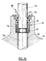
- FIG. 3a shows a block diagram of these valves 23, 24, 33 to 36 and an embodiment of a conventional type of sealing is shown in FIG. 3b, that is to say that FIG. 3b shows diagrammatically the manner in which the sealing valves 23, 24, 33 to 36 is usually provided.
- each valve conventionally comprises a valve body 41 surmounted by a portion 44 forming an arch and comprising, by elsewhere, an actuator 43, a drive shaft 54, a sealing system 51 shaft 54 and connection flanges 46 for receiving the ends of two pipes 49.
- the actuator 43 of a valve makes it possible to maneuver the shutter 48 via the operating shaft 54, so as to open or close the valve, that is to say, authorize or prohibit any passage of fluid.
- the actuator 43 surmounting the portion 44 forming an arch is actuated pneumatically by means of instrument air supplied to the valve by a instrument air supply pipe 45.
- Sealing between the PSA installation pipe circuit and the environment outside is carried out by the sealing system 51 of the shaft 54.
- such a sealing system 51 must limit possibilities of communication of fluids between the pipe circuit of the PSA installation and the external environment 80, while allowing easy maneuvering of the shaft 54, that is to say here its rotation about its axis.
- seal 51 consists of a series of seals 76 carried by a stop 77 and O-rings 75 placed in a seal holder 74, the whole being partially fixed to the valve body 41 and compressed by clamping screws 73 or the like, so as to limit exchanges between, on the one hand, the process fluid present in the level of clearance or space 78 existing between the valve body 41 and the shaft of maneuver 54 and, on the other hand, the ambient environment 80 ambient.
- means for maintenance 52 of a protective gaseous atmosphere are arranged around the sealing means 51 of at least one of the valves 13, 17, 14, 18.
- valve 35 As an example, we will consider valve 35.
- the means 52 for holding a protective gas atmosphere include an enclosure 53 forming a sleeve around the sealing means 51 of the valve 35, possibly including at least part of the operating means 50 of the valve 35, in particular part of the operating shaft 54 and the external part of the system seal 51 of the shaft 54.
- the enclosure 53 is formed by four side walls peripherals 55a, 55b, 55c, 55d, of a wall forming a ceiling or cover 55e and of a wall forming a bottom 55f.
- peripheral side walls 55c, 55d, the cover 55e and the bottom 55f are integral with each other and form a three-dimensional structure single hollow, while the side walls 55a, 55b are fixed on this hollow three-dimensional structure by suitable fixing means, for example example using threaded rods 60 and bolts 61, holes 62 drilled in the side walls 55a, 55b for passing the threaded rods 60 to through the hollow three-dimensional structure.
- the lateral wall 55a of the enclosure 53 is pierced with an orifice 56 for passage of gas communicating with a line 57 of protective gas supply connected to a source of shielding gas (not shown) to supply power the interior of said enclosure 53 with protective gas originating from said source of shielding gas, such as storage capacity, production of "instrument” air or one of the adsorbers 1, 2.
- Attachment of line 57 for supplying shielding gas to side wall 55a of the enclosure 53 is produced by means of a hollow bent piece 63.
- the cover 55e and the bottom 55f of the hollow three-dimensional structure have holes 71, 70, respectively, crossed by the operating shaft 54.
- the maintenance of a gaseous atmosphere protective around the sealing means 51 of the valve 35 to allow create and / or maintain a protective gas atmosphere sealing 51 is preferably done by operating a gas sweep of the sealing means 51 by means of the protective gas introduced through the orifice 56 in enclosure 53.
- a gas or a gas mixture substantially free from the harmful impurity for example example a gas or gas mixture free of water vapor, for example dry air or dried oxygen, when the impurity to be combated is vapor of water.
- instrument In known manner, air called “instrument” is compressed air under a pressure, for example, of the order of 8 bars, filtered, deoiled, dried through adequate equipment and used as a working fluid to maneuver the valves via actuators or for pneumatic instrumentation.
- the pressure of the shielding gas introduced into the enclosure 53 is preferably higher than atmospheric pressure, generally overpressure being of the order of 10 to 100 mbar greater than atmospheric pressure.
- the enclosure 53 thus formed is hollow and relatively sealed, and the impurities atmospheric, in particular water vapor, cannot penetrate it by the overpressure generated by the introduction of the shielding gas into the enclosure 53.
- a material with a strong affinity for impurity whose introduction is to be avoided in the PSA installation circuit for example humidity. So we could completely or partially fill the enclosure 53, for example, with a material desiccant of the silica gel or activated alumina type, which could be replaced periodically to avoid saturation. Ease of intervention on a unit industrial allows to consider frequent replacements of this material. Of in general, using such a material can complement the introduction of a protective gas sweep either as safety in the event of a temporary shutdown supply of shielding gas, either to reduce the residual quantity impurities likely to be present in the shielding gas used.
Abstract
Description
L'invention concerne une installation et un procédé de traitement cyclique de fluide par adsorption avec mise en oeuvre, durant une partie du cycle de traitement du fluide, d'une pression inférieure à la pression atmosphérique, en particulier un procédé type VSA de séparation et/ou de purification d'un flux gazeux contenant essentiellement de l'oxygène et de l'azote, tel l'air.The invention relates to an installation and a method for cyclic treatment. of fluid by adsorption with implementation, during part of the cycle of treatment of the fluid, of a pressure lower than atmospheric pressure, in particular a VSA type process for separation and / or purification of a stream gaseous containing essentially oxygen and nitrogen, such as air.
Il est connu que les gaz et les mélanges gazeux trouvent de nombreuses applications au plan industriel. Ainsi, les gaz de l'air, tels notamment l'oxygène et l'azote, sont couramment utilisés dans de nombreux domaines, tel notamment le domaine de l'électronique, le domaine de la combustion, le domaine médical, le domaine alimentaire, le domaine du soudageIt is known that gases and gas mixtures find many industrial applications. Air gases, such as oxygen and nitrogen, are commonly used in many fields, such as electronics, combustion, medical, food, welding
Actuellement, l'une des techniques utilisées pour produire ou purifier les gaz, en particulier les gaz de l'air, est la technique dite "PSA" (Pressure Swing Adsorption), c'est-à-dire adsorption avec variations de pression.Currently, one of the techniques used to produce or purify gas, in particular air gases, is the so-called "PSA" technique (Pressure Swing Adsorption), i.e. adsorption with pressure variations.
Selon cette technique PSA, lorsque le mélange gazeux à séparer est, par exemple, de l'air et que le composant à récupérer est l'oxygène, par exemple, ledit oxygène est séparé du mélange gazeux que constitue l'air ambiant grâce à une adsorption préférentielle d'au moins l'azote sur un ou plusieurs matériaux adsorbant préférentiellement au moins l'azote et soumis à des cycles de pression donnée dans une ou plusieurs zones de séparation, en général un ou des adsorbeurs.According to this PSA technique, when the gas mixture to be separated is, for example example, air and the component to be recovered is oxygen, for example, said oxygen is separated from the gaseous mixture of ambient air thanks to a preferential adsorption of at least nitrogen on one or more materials preferably adsorbing at least nitrogen and subjected to pressure cycles given in one or more separation zones, in general one or more adsorbers.
L'oxygène qui ne s'adsorbe pas ou peu est récupéré en sortie de la ou des zones de séparation à une pureté, en général, supérieure à 90 %.The oxygen which does not adsorb or little is recovered at the outlet of the separation zones with a purity, in general, greater than 90%.
En d'autres termes, la technique de l'adsorption est couramment utilisée pour séparer les différents constituants d'un mélange gazeux, de manière à produire directement, dans le cas de l'air, de l'oxygène et/ou de l'azote relativement pur ou, selon le cas, d'en éliminer certaines impuretés, par exemple la vapeur d'eau, le dioxyde de carbone, les oxydes d'azote, les traces éventuelles d'hydrocarbures... dont la présence peut nuire au bon fonctionnement des équipements situés en aval, telles que des unités de fractionnement d'air par voie cryogénique, par exemple.In other words, the adsorption technique is commonly used to separate the different constituents of a gas mixture, so that directly produce, in the case of air, oxygen and / or relatively nitrogen pure or, as the case may be, to eliminate certain impurities, for example steam water, carbon dioxide, nitrogen oxides, any traces hydrocarbons ... the presence of which can affect the proper functioning of downstream equipment, such as air fractionation units cryogenic, for example.
De façon plus générale, un procédé PSA de séparation d'un mélange gazeux comprenant un premier composé s'adsorbant préférentiellement sur un matériau adsorbant et un deuxième composé s'adsorbant moins préférentiellement sur ledit matériau adsorbant que ledit premier composé, en vue de la production dudit deuxième composé, comprend de manière cyclique :
- une étape d'adsorption préférentielle d'au moins ledit premier composé sur ledit matériau adsorbant, à une pression d'adsorption dite "pression haute", avec récupération d'au moins une partie du deuxième composé ainsi produit;
- une étape de désorption du premier composé ainsi piégé par l'adsorbant, à une pression de désorption inférieure à la pression d'adsorption, dite "pression basse";
- une étape de recompression de la zone de séparation comprenant l'adsorbant, par passage de ladite pression basse à ladite pression haute.
- a step of preferential adsorption of at least said first compound on said adsorbent material, at an adsorption pressure called "high pressure", with recovery of at least part of the second compound thus produced;
- a step of desorption of the first compound thus trapped by the adsorbent, at a desorption pressure lower than the adsorption pressure, called "low pressure";
- a step of recompressing the separation zone comprising the adsorbent, by passing from said low pressure to said high pressure.
Dit autrement, dans les installations industrielles basées sur la technique de l'adsorption, un flux gazeux à traiter s'écoule à travers un ou plusieurs lits d'adsorbants. Après un certain temps de fonctionnement, les matériaux adsorbants sont saturés et ne sont donc plus aptes à fixer de nouvelles molécules de gaz.In other words, in industrial installations based on the technique of adsorption, a gas flow to be treated flows through one or more beds adsorbents. After a certain operating time, the adsorbent materials are saturated and are therefore no longer able to fix new gas molecules.
Il est alors nécessaire de procéder à la régénération du ou des lits d'adsorbant. Pour ce faire, plusieurs techniques de régénération ou de désorption sont utilisables, par exemple l'élévation de température, l'abaissement de la pression, l'élution par un gaz de balayage.... ces diverses techniques pouvant être utilisées conjointement ou successivement, si nécessaire.It is then necessary to regenerate the bed (s) adsorbent. To do this, several regeneration or desorption techniques can be used, for example raising the temperature, lowering the pressure, elution with a sweeping gas .... these various techniques can be used jointly or successively, if necessary.
Actuellement, de nombreux procédés mettent en oeuvre une pression de régénération inférieure à la pression atmosphérique, c'est-à-dire inférieure à 1 bar (105 Pa). Une telle technique qui constitue un cas particulier de procédé PSA est habituellement appelée technique ou procédé "VPSA" (Vacuum "Pressure" Swing Adsorption) ou plus simplement appelée procédé "VSA" (Vacuum Swing Adsorption), c'est-à-dire adsorption avec variation de pression et mise sous vide. Currently, many processes use a regeneration pressure below atmospheric pressure, that is to say less than 1 bar (10 5 Pa). Such a technique which constitutes a particular case of PSA process is usually called "Vacuum" Pressure "Swing Adsorption (VPSA) technique or more simply called" Vacuum Swing Adsorption "(VSA) process, that is to say adsorption with pressure variation and evacuation.
A titre d'exemple, on peut citer :
- le document US-A-5,042,994 décrivant un procédé de séparation des gaz de l'air comprenant une pression de désorption inférieure à la pression atmosphérique, destinée à la coproduction d'azote de haute pureté et d'oxygène moyenne pureté,
- le document US-A-5,156,657 portant sur un procédé PSA pour éliminer l'eau et le CO2 présents dans un flux d'air, avec mise en oeuvre d'une étape de purge sous vide,
- le document US-A-5,395,427 concernant un procédé PSA avec deux étages d'adsorption pour la production d'oxygène de haute pureté avec mise sous vide des deux étages d'adsorption au cours d'un cycle de production,
- le document US-A-5,463,869 ayant trait à un procédé intégré adsorption/distillation cryogénique pour la séparation d'air avec mise en oeuvre d'un cycle de type VSA pendant ladite séparation, et
- le document US-A-5,785,740 portant sur cycle trans-atmosphérique de production, en particulier, d'oxygène.
- document US Pat. No. 5,042,994 describing a process for the separation of gases from air comprising a desorption pressure below atmospheric pressure, intended for the co-production of high-purity nitrogen and medium-purity oxygen,
- document US-A-5,156,657 relating to a PSA process for removing water and CO 2 present in an air flow, with the use of a vacuum purging step,
- document US-A-5,395,427 concerning a PSA process with two adsorption stages for the production of high purity oxygen with vacuuming of the two adsorption stages during a production cycle,
- document US-A-5,463,869 relating to an integrated cryogenic adsorption / distillation process for the separation of air with the use of a VSA type cycle during said separation, and
- document US-A-5,785,740 relating to the trans-atmospheric cycle of production, in particular, of oxygen.
Il apparaít donc que, comme le montrent ces documents, la mise en oeuvre dans un procédé PSA d'étapes de mise sous vide, c'est-à-dire à une pression inférieure à la pression atmosphérique, de manière à obtenir un procédé VSA, est connu et classique.It therefore appears that, as these documents show, the implementation in a PSA process of evacuation steps, i.e. at a pressure lower than atmospheric pressure, so as to obtain a VSA process, is known and classic.
Actuellement, les matériaux zéolitiques sont les adsorbants les plus utilisés dans les installations de séparation ou de purification de gaz mettant en oeuvre un procédé de type PSA ou VSA. De telles zéolites sont notamment décrites dans les documents EP-A-486384, EP-A-606848, EP-A-589391, EP-A-589406, EP-A-548755, US-A-268023, EP-A-109063, EP-A-827771 et EP-A-760248.Currently, zeolitic materials are the most used adsorbents in gas separation or purification installations using a PSA or VSA type process. Such zeolites are notably described in the documents EP-A-486384, EP-A-606848, EP-A-589391, EP-A-589406, EP-A-548755, US-A-268023, EP-A-109063, EP-A-827771 and EP-A-760248.
Cependant, ces adsorbants, en particulier les zéolites, présentent une très grande sensibilité aux polluants de toute nature susceptibles de venir les contaminer et les inactiver, notamment les polluants présents dans l'air atmosphérique.However, these adsorbents, in particular zeolites, have a very high sensitivity to pollutants of all kinds likely to come contaminate and inactivate them, including air pollutants atmospheric.
Ainsi, il est connu que, dans les unités de traitement d'air, les traces d'eau diminuent considérablement les performances des zéolites utilisées soit pour arrêter le CO2 avant séparation cryogénique de l'air, soit pour arrêter l'azote lorsque l'on souhaite produire de l'oxygène. Thus, it is known that, in air treatment units, traces of water considerably reduce the performance of zeolites used either to stop the CO 2 before cryogenic separation of the air, or to stop the nitrogen when the 'we want to produce oxygen.
C'est pour cette raison que l'on dispose habituellement, en entrée des adsorbeurs servant à la séparation d'air, une couche d'un adsorbant adapté à l'élimination de l'eau, laquelle est suivie d'une ou plusieurs couches d'un ou plusieurs adsorbants plus spécifiquement destinés à arrêter le composé gazeux à éliminer, par exemple le CO2, l'azote ou d'autres composés gazeux, selon le cas considéré, comme expliqué ci-dessus. Classiquement, la couche d'adsorbant adapté à l'élimination de l'eau est, par exemple, une couche d'alumine activée, éventuellement dopée, ou du gel de silice, voire une zéolite présentant une affinité élevée pour l'eau et régénérable dans les conditions normales de fonctionnement de l'unité.It is for this reason that a layer of an adsorbent suitable for removing water is usually placed at the inlet of the adsorbers serving for the separation of air, followed by one or more layers. one or more adsorbents more specifically intended to stop the gaseous compound to be eliminated, for example CO 2 , nitrogen or other gaseous compounds, as the case may be, as explained above. Conventionally, the adsorbent layer suitable for removing water is, for example, a layer of activated alumina, optionally doped, or silica gel, or even a zeolite having a high affinity for water and regenerable under normal unit operating conditions.
Il est également connu d'effectuer des régénérations périodiques par élévation de la température et d'effectuer, en outre, des régénérations dites exceptionnelles à température plus élevée que la température nominale de régénération afin d'éliminer les traces d'humidité qui sont susceptibles de s'accumuler dans l'adsorbant, c'est-à-dire dans la zéolite, au cours du temps et malgré les phases de régénération périodiques.It is also known to carry out periodic regenerations by rise in temperature and perform, in addition, so-called regenerations exceptional at temperatures higher than the nominal temperature of regeneration in order to remove traces of moisture which are liable to accumulate in the adsorbent, that is to say in the zeolite, over time and despite the periodic regeneration phases.
En général, ces régénérations se font avec un débit de régénération réduit profitant ainsi de la puissance installée du réchauffeur pour obtenir une température de sortie plus élevée, par exemple 250°C au lieu de 150°C en fonctionnement normal, et atteindre après balayage du lit d'adsorbant un taux d'humidité résiduelle très faible permettant d'utiliser de manière optimale la zéolite.In general, these regenerations are done with a regeneration rate thus taking advantage of the installed power of the heater to obtain a higher outlet temperature, for example 250 ° C instead of 150 ° C in normal operation, and after scanning the adsorbent bed reach a rate very low residual moisture allowing optimal use of the zeolite.
Dans le même domaine, le document FR-A-9409162 divulgue un dispositif anti-pollution permettant d'éviter toute entrée d'humidité au niveau des zéolites pendant les phases d'arrêt des unités d'adsorption.In the same field, the document FR-A-9409162 discloses a device anti-pollution to prevent any entry of moisture at the zeolites during the shutdown phases of the adsorption units.
Pour ce faire, lors des arrêts, on isole chaque adsorbeur et on met son entrée en communication libre avec l'atmosphère.To do this, during shutdowns, we isolate each adsorber and put its entry into free communication with the atmosphere.
En outre, chaque adsorbeur, qui est sous vide durant chaque arrêt, est ramené à la pression atmosphérique par introduction dans celui-ci d'un gaz pratiquement sec et préférentiellement par le gaz de production.In addition, each adsorber, which is under vacuum during each stop, is reduced to atmospheric pressure by introducing a gas into it practically dry and preferably by the production gas.
De cette façon, tous les échanges gazeux résiduels avec l'atmosphère, dus aux variations de température des adsorbants par exemple, se font à travers le lit servant à la dessiccation du gaz à traiter et donc sans dommage pour la zéolite située en aval. In this way, all residual gas exchanges with the atmosphere, due to the temperature variations of the adsorbents for example, are made through the bed used to dry the gas to be treated and therefore without damage to the zeolite located downstream.
L'application industrielle des dispositifs, installations et procédés décrits ci-dessus a ainsi permis de conduire à des performances quasiment inchangées sur des périodes de plusieurs années, notamment en vue de la production d'oxygène par adsorption, ou pour lesquelles, dans les cas extrêmes, la baisse de performance n'était que de quelques pour cents, c'est-à-dire industriellement acceptable.The industrial application of the devices, installations and processes described above has thus led to almost unchanged performance on periods of several years, in particular for the production of oxygen by adsorption, or for which, in extreme cases, the drop in performance was only a few percent, i.e. industrially acceptable.
Il s'avère néanmoins que sur les unités de nouvelle génération, le vieillissement semble s'être accéléré et que, dès les premières années de fonctionnement, on observe une diminution notable des performances.However, it turns out that on new generation units, the aging seems to have accelerated and that, from the first years of operation, there is a significant decrease in performance.
Compte tenu des conséquences économiques négatives liées à cette dégradation, ce phénomène nouveau a fait l'objet d'études poussées pour en déterminer la cause.Given the negative economic consequences linked to this degradation, this new phenomenon has been the subject of extensive studies to determine the cause.
Ainsi, il a été établi, à partir de prélèvements statistiques d'échantillons d'adsorbants sur des unités industrielles, que la baisse de performances était attribuable à la présence de traces d'eau dans la zéolite, certes en quantité limitée mais toutefois supérieure à celle mesurée lors du démarrage de ces unités.Thus, it has been established, from statistical samples adsorbents on industrial units, that the drop in performance was attributable to the presence of traces of water in the zeolite, certainly in limited quantity but however greater than that measured when these units were started up.
A l'inverse d'unités industrielles plus anciennes qui avaient pu connaítre de tels problèmes avant l'application de l'enseignement du document FR-A-9409162, la pollution par l'humidité ne touchait pas de manière bien marquée et assez sensible une zone de zéolite proche de la sortie de chaque adsorbeur, i.e. le côté production, mais la totalité de la masse d'adsorbant.Unlike older industrial units that may have known such problems before applying the teaching of document FR-A-9409162, the humidity pollution did not affect in a marked way and enough sensitive a zone of zeolite close to the outlet of each adsorber, i.e. the side production, but the entire mass of adsorbent.
Ainsi, par exemple, avant la mise en oeuvre du dispositif décrit par le document FR-A-9409162, un cas de pollution avait pu être identifié et attribué à la phase de repressuration à contre-courant d'un adsorbeur arrêté systématiquement sous vide, via une vanne fuyarde du côté production, avec de l'oxygène chargé en eau au travers d'une machine de compression de type humide. Une analyse du tamis moléculaire utilisé dans cette unité de production a mis en évidence une pollution massive de la couche supérieure dudit tamis, côté production, par de l'humidité dont la source est, sans aucun doute, l'eau contenue dans la pompe à anneau liquide située à proximité immédiate et en aval de l'unité de production.Thus, for example, before the implementation of the device described by the document FR-A-9409162, a case of pollution could be identified and attributed to the repressuring phase against the current of an adsorber systematically stopped under vacuum, via a leaking valve on the production side, with oxygen charged in water through a wet type compression machine. An analysis of molecular sieve used in this production unit has highlighted a massive pollution of the upper layer of said sieve, production side, by moisture, the source of which is undoubtedly the water in the pump liquid ring located in the immediate vicinity and downstream of the production unit.
Dans le cas, des problèmes rencontrés avec les unités industrielles plus récentes, il s'agit en fait, d'une pollution lente et progressive, c'est-à-dire non pas ponctuelle ou par paliers. In the case, problems encountered with more industrial units recent, it is in fact, a slow and progressive pollution, that is to say not ad hoc or in stages.
Des mesures et essais opérés sur des unités industrielles ont permis d'en connaítre la cause et de comprendre pourquoi ce phénomène n'était pas apparu précédemment sur des unités industrielles plus anciennes.Measurements and tests carried out on industrial units have made it possible to know the cause and understand why this phenomenon did not appear previously on older industrial units.
Cela va être expliqué maintenant en prenant l'exemple d'une unité de type PSA de production d'oxygène à partir d'air comportant deux adsorbeurs mais le phénomène est général et concerne tous les cas de régénération sous vide. De même, le cycle considéré à titre d'exemple correspond à celui décrit par le document US-A-5,223,004 ; toutefois, ce choix n'est nullement limitatif.This will be explained now by taking the example of a type unit PSA for the production of oxygen from air comprising two adsorbers but the phenomenon is general and concerns all cases of vacuum regeneration. Of even, the cycle considered by way of example corresponds to that described by the document US-A-5,223,004; however, this choice is in no way limiting.
Le document US-A-5,223,004 est donc intégré ici par référence, en
particulier les figures 1 et 2 de ce document, ainsi que les passages s'y rapportant,
à savoir : colonne 3, lignes 20 à 68 et colonne 4, lignes 1 à 24.The document US-A-5,223,004 is therefore incorporated here by reference, in
particularly Figures 1 and 2 of this document, as well as the passages relating thereto,
namely: column 3,
A la lecture de ce document, on comprend que :
- les lignes du côté gaz de production sont régulièrement et cycliquement mises sous vide ;
- il existe plusieurs étapes au cours desquelles de l'oxygène retourne à contre-courant dans les adsorbeurs pendant l'étape de pressurisation initiale, pendant l'étape de pompage de l'oxygène contenu notamment dans lesdites lignes et pendant l'étape d'élution ;
- ce type de cycle rend nécessaire du côté de la sortie production de chaque adsorbeur, un certain nombre de vannes qui, successivement, isolent ou mettent en communication fluidique les divers équipements de l'unité PSA.
- the lines on the production gas side are regularly and cyclically evacuated;
- there are several stages during which oxygen returns against the current in the adsorbers during the initial pressurization stage, during the stage of pumping the oxygen contained in particular in said lines and during the elution stage ;
- this type of cycle makes it necessary on the production output side of each adsorber, a certain number of valves which, successively, isolate or put in fluid communication the various equipment of the PSA unit.
Les vannes utilisées sont de type tout-ou-rien, comme celles représentées en figure 2 du document US-A-5,223,004, ou, selon le cas, à ouverture et/ou fermeture contrôlée, en particulier par des rampes.The valves used are of the all-or-nothing type, like those shown in FIG. 2 of document US-A-5,223,004, or, as the case may be, opening and / or controlled closure, in particular by ramps.
De façon générale, il est utilisé des vannes de type papillon qui entraínent de faibles variations de pression lorsque l'ouverture desdites vannes est de l'ordre de 100% et permettent de minimiser la consommation énergétique de l'installation.Generally, butterfly type valves are used which drive small pressure variations when the opening of said valves is of the order 100% and minimize the energy consumption of the installation.
En particulier, des vannes de type papillon ont été parfaitement adaptées aux conditions de fonctionnement des unités PSA, c'est-à-dire qu'ont été pris en compte le grand nombre de manoeuvre, la vitesse d'ouverture/fermeture élevée, l'étanchéité nécessaire, les caractéristiques du procédé à mettre en oeuvre......In particular, butterfly type valves have been perfectly adapted the operating conditions of the PSA units, i.e. have been taken into account counts the large number of operations, the high opening / closing speed, the necessary tightness, the characteristics of the process to be implemented ......
Parmi les évolutions engendrées par cette adaptation, on peut noter le grand choix de matériaux disponibles pour le siège, les paliers, les étanchéités (métal, élastomère, plastomère, PTFE chargé...), l'amélioration des cinématiques et des sections de passage... A titre d'exemple, le couple nécessaire à l'ouverture et/ou à la fermeture de l'obturateur d'une vanne de type papillon peut être limité en utilisant une cinématique à double excentration. Dans ce cas, l'axe de rotation est décalé par rapport au plan de l'obturateur et excentré par rapport à l'axe de la tuyauterie . Cette conception diminue fortement les frottements entre siège et portée d'étanchéité de l'obturateur. De même, l'arbre de rotation de l'obturateur peut être en deux parties, laissant ainsi la zone centrale libre pour la circulation du fluide, ce qui a pour effet de diminuer les pertes de charge à travers la vanne.Among the changes brought about by this adaptation, we can note the large choice of materials available for the seat, bearings, seals (metal, elastomer, plastomer, charged PTFE ...), improved kinematics and passage sections ... For example, the torque required to open and / or closing the shutter of a butterfly type valve can be limited by using double eccentric kinematics. In this case, the axis of rotation is offset from the plane of the shutter and offset from the axis of the piping. This design greatly reduces friction between seat and sealing surface of the shutter. Likewise, the shutter rotation shaft can be in two parts, thus leaving the central area free for the circulation of fluid, which has the effect of reducing the pressure losses through the valve.
De façon générale, les étanchéités vis-à-vis du milieu extérieur au passage de l'arbre de rotation sont de type varié et mettent en oeuvre les diverses techniques (tresse, joint torique, joint en V, double étanchéité....) et matériaux connus.In general, the seals vis-à-vis the external environment at the passage of the rotation shaft are of varied type and implement the various techniques (braid, O-ring, V-ring, double seal, etc.) and materials known.
Sur certains modèles de vannes, les paliers sont facilement remplaçables y compris le palier opposé à l'axe de manoeuvre qui peut constituer, par exemple, une cartouche facilement démontable sans avoir à ouvrir ou démonter la vanne proprement dite.On some valve models, the bearings are easily replaceable y including the bearing opposite the operating axis which may constitute, for example, an easily removable cartridge without having to open or dismantle the valve proper.
Malgré toutes ces adaptations, il est apparu au cours des essais effectués sur les unités industrielles que c'est au niveau de ces étanchéités vis-à-vis du milieu extérieur, c'est-à-dire de l'atmosphère ambiante, que résidait le problème de la baisse des performances au cours du temps rencontrées sur les unités PSA les plus récentes.Despite all these adaptations, it appeared during the tests carried out on industrial units that it is at the level of these seals vis-à-vis the external environment, that is to say of the ambient atmosphere, that resided the problem of the decrease in performance over time encountered on PSA units most recent.
En fait, le vieillissement prématuré de l'adsorbant, en particulier des particules de zéolites, peut s'expliquer par l'évolution actuelle des unités PSA, en particulier des unités PSA de séparation d'air.In fact, the premature aging of the adsorbent, in particular zeolite particles, can be explained by the current evolution of PSA units, in especially PSA air separation units.
En effet, les unités PSA récentes se caractérisent par une utilisation de tamis moléculaire, c'est-à-dire d'adsorbant, de plus en plus performant et par la réduction des temps de cycle.Indeed, recent PSA units are characterized by the use of molecular sieve, that is to say of adsorbent, more and more efficient and by the reduction of cycle times.
En reprenant l'exemple de la séparation d'air pour produire de l'oxygène, il s'est produit une évolution depuis des unités PSA mettant en oeuvre des adsorbants de type zéolite 13X ou 5A et fonctionnant avec des temps de cycle de plusieurs minutes vers des unités PSA mettant en oeuvre des adsorbants de type zéolite X ou LSX échangée par des cations métallique, tel le lithium, et fonctionnant avec des temps de cycle de l'ordre de quelques dizaine de secondes, typiquement moins de 90 secondes.Using the example of air separation to produce oxygen, it an evolution has occurred from PSA units implementing 13X or 5A zeolite type adsorbents and operating with cycle times of several minutes to PSA units using adsorbents of the type zeolite X or LSX exchanged by metal cations, such as lithium, and operating with cycle times of the order of a few tens of seconds, typically less than 90 seconds.
L'augmentation intrinsèque de la productivité du matériau adsorbant couplée avec la réduction du temps de cycle conduit à utiliser actuellement entre 5 et 10 fois moins de zéolite qu'une unité classique, telle une unité mettant en oeuvre des adsorbants de type zéolite 13X ou 5A, et ce, pour une même production.The intrinsic increase in the productivity of the adsorbent material coupled with the reduction in cycle time currently leads to use between 5 and 10 times less zeolite than a conventional unit, such as a unit implementing 13X or 5A zeolite type adsorbents for the same production.
On notera, d'ailleurs, que c'est cette réduction substantielle des quantités d'adsorbant nécessaire qui a permis de diminuer le coût de l'investissement car les nouveaux matériaux, plus élaborés, peuvent coûter entre environ 3 à 6 fois plus que les matériaux plus classiques, telle la zéolite 13X ou 5A.It will be noted, moreover, that it is this substantial reduction in the quantities adsorbent required which reduced the cost of investment because the new, more elaborate materials can cost between about 3 to 6 times more than more conventional materials, such as zeolite 13X or 5A.
Par ailleurs, à production donnée, les autres équipements ont relativement peu changé de taille, en particulier les lignes de tuyauterie du côté de la sortie production des adsorbeurs ; les débits en circulation étant toujours du même ordre de grandeur.Furthermore, for a given production, the other equipment has relatively little change in size, especially the piping lines on the outlet side production of adsorbers; the debits in circulation being always of the same order of greatness.
De là, en reprenant l'exemple du cycle MPSA cité ci-avant, on comprend que si les quantités de gaz échangées au cours de chaque étape sont plus faible du fait de la réduction du volume d'adsorbant, les débits quant à eux sont pratiquement inchangés du fait de la réduction de la durée de ces mêmes étapes. A même perte de charge et pour une production donnée, il est donc normal que le diamètre des tuyauteries soit inchangé.From there, taking the example of the MPSA cycle cited above, we understand only if the quantities of gas exchanged during each stage are lower due to the reduction in the volume of adsorbent, the flow rates are practically unchanged due to the reduction in the duration of these same stages. At the same pressure drop and for a given production, it is therefore normal for the pipe diameter is unchanged.
En pratique, les performances intrinsèques des unités s'étant améliorées conjointement avec l'évolution du tamis, les pertes énergétiques dues aux pertes de charge dans le système ont pris en proportion plus d'importance qu'auparavant et la tendance à plutôt été de les diminuer, c'est-à-dire d'augmenter le diamètre de certaines tuyauteries.In practice, the intrinsic performances of the units having improved together with the evolution of the sieve, the energy losses due to the losses load in the system have become proportionately more important than before and the tendency was rather to decrease them, that is to say to increase the diameter of some piping.
De manière générale, on peut retenir que l'évolution des unités PSA a conduit à installer des quantités d'adsorbant de plus en plus faible tout en maintenant des circuits de liaison de dimensions inchangées.In general, it can be noted that the evolution of PSA units has leads to the installation of increasingly smaller amounts of adsorbent while now connecting circuits of unchanged dimensions.
D'autre part, il découle de ce qui précède que le nombre de manoeuvres de vannes n'a fait qu'augmenter pendant cette évolution, en première approximation de façon inversement proportionnelle à la durée de cycle.On the other hand, it follows from the above that the number of maneuvers of valves only increased during this evolution, as a first approximation inversely proportional to the cycle time.
A vannes identiques, le vieillissement des étanchéités est donc nettement plus rapide sur les unités récentes. With identical valves, the aging of the seals is therefore clearly faster on recent units.
Les entrées d'air atmosphérique humide vers les circuits procédés sous vide à travers ces étanchéités, que l'on peut observer au bout de deux ou trois mois de service, correspondent maintenant, à technologie égale par ailleurs, à celles que l'on obtenait précédemment au bout d'un ou deux ans.The humid atmospheric air inlets to the process circuits under vacuum through these seals, which can be observed after two or three months of service, now correspond to technology equal to those previously obtained after one or two years.
Du fait des échanges gazeux entre adsorbeurs, l'essentiel de cette humidité va préférentiellement se piéger et s'accumuler sur l'adsorbant, en particulier la zéolite, au lieu d'être entraíné et évacué par le flux de production.Due to gas exchanges between adsorbers, most of this humidity will preferentially trap and accumulate on the adsorbent, in particular the zeolite, instead of being entrained and evacuated by the production flow.
Or, la puissance de régénération qui est mise en oeuvre dans toute unité PSA, qui est nécessaire pour assurer un fonctionnement cyclique de unité, tend à répandre cette humidité, à partir de la zone de zéolite située en sortie d'adsorbeur, dans toute la masse de l'adsorbant conduisant ainsi progressivement à une pollution touchant toute la masse d'adsorbant.Now, the regenerative power that is implemented in any unit PSA, which is necessary for cyclical unit operation, tends to spread this humidity from the zeolite zone located at the outlet of the adsorber, throughout the mass of the adsorbent thus gradually leading to a pollution affecting the entire mass of adsorbent.
En d'autres termes, les unités PSA récentes voient s'accumuler une quantité significative d'humidité sur le tamis qu'elles contiennent dans leurs adsorbeurs, du fait de la taille inchangée des vannes et de leur vieillissement prématuré dû à l'augmentation du nombre de manoeuvres, cette accumulation étant d'autant plus néfaste que le volume d'adsorbant utilisé est réduit, ce qui est le cas avec les unités récentes.In other words, recent PSA units are seeing an accumulation significant amount of moisture on the sieve they contain in their adsorbers, due to the unchanged size of the valves and their aging premature due to the increase in the number of operations, this accumulation being all the more harmful that the volume of adsorbent used is reduced, which is the case with recent units.
L'effet des traces d'humidité étant au moins aussi sensible pour les nouveaux adsorbants, telles les zéolites Li-X ou Li-LSX, que pour les adsorbants plus classiques, telles les zéolites 13X ou 5A, on conçoit que la baisse de performance pour une même durée de fonctionnement, 6 mois ou un an par exemple, puisse être supérieure en moyenne d'un ordre de grandeur pour les unités actuelles récentes à cycle court et utilisant un adsorbant zéolitique performant que pour les unités classiques, et donc se faire sentir quelques mois seulement après la mise en service alors que ce phénomène passait inaperçu, auparavant.The effect of traces of moisture being at least as noticeable for new adsorbents, such as zeolites Li-X or Li-LSX, only for adsorbents more conventional, such as 13X or 5A zeolites, we can see that the drop in performance for the same operating period, 6 months or a year per example, could be on average an order of magnitude higher for current short cycle current units using a zeolitic adsorbent efficient than for conventional units, and therefore be felt for a few months only after commissioning when this phenomenon went unnoticed, before.
Une première solution évidente pour résoudre ce problème d'étanchéité des vannes et d'entrée néfaste d'humidité consiste à utiliser des vannes adéquates, c'est-à-dire totalement étanches vis-à-vis de l'extérieur.A first obvious solution to solve this problem of watertightness of valves and harmful entry of humidity consists in using adequate valves, that is to say completely waterproof vis-à-vis the outside.
Plusieurs types de vannes répondant à ces critères ont été développées pour diverses applications et on peut citer, par exemple, les vannes équipées de soufflets. Several types of valves meeting these criteria have been developed for various applications and we can cite, for example, valves fitted with bellows.
Toutefois, ces vannes "étanches" sont généralement de coût élevé, moins facilement disponibles dans le commerce que les vannes classiques, souvent peu ou mal adaptées aux cycles courts des unités PSA et de démontage compliqué en vue de leur entretien du fait de leur système d'étanchéité complexe.However, these "sealed" valves are generally of high cost, less readily available commercially than conventional valves, often few or poorly suited to the short cycles of PSA units and complicated disassembly in view of their maintenance due to their complex sealing system.
De plus, remplacer toutes les vannes "non-étanches" par des vannes "étanches" sur une unité PSA industrielle déjà en fonctionnement et pour laquelle se pose le problème de la perte de performance de l'adsorbant mentionné ci-dessus n'est pas envisageable car un tel remplacement serait complexe à réaliser et de coût très élevé, d'autant qu'il rend obligatoire un arrêt total de l'unité PSA et donc de la production de gaz pendant toute la durée de l'intervention visant à ce remplacement, en engendrant par là-même des pertes importantes de productivité pendant plusieurs jours ou plusieurs semaines, voire plusieurs mois.In addition, replace all "leaky" valves with valves "waterproof" on an industrial PSA unit already in operation and for which there is the problem of the loss of performance of the adsorbent mentioned above is not possible because such a replacement would be complex to carry out and of very high cost, especially since it makes a total shutdown of the PSA unit compulsory and therefore gas production throughout the duration of the intervention aimed at this replacement, thereby causing significant productivity losses for several days or weeks, or even months.
En outre, une régénération in situ du tamis pollué est théoriquement possible mais les coûts entraínés par une telle régénération sont tels que cette solution n'est généralement pas retenue sauf cas particulier.In addition, an in situ regeneration of the polluted sieve is theoretically possible but the costs involved in such regeneration are such that this solution is generally not adopted except in special cases.
En effet, pour régénérer une telle zéolite, il faut la balayer pendant plusieurs heures avec un gaz essentiellement sec à température élevée, de l'ordre de 250 à 350°C.Indeed, to regenerate such a zeolite, it must be swept for several hours with essentially dry gas at high temperature, in the range of 250 to 350 ° C.
Il peut être, par ailleurs, nécessaire avec certains adsorbants particuliers, telles les zéolites par exemple, de respecter aussi des vitesses de montée en température et des paliers à température intermédiaire pour éviter de dégrader la phase zéolitique.It may also be necessary with certain particular adsorbents, such as zeolites, for example, to also observe rise rates temperature and intermediate temperature bearings to avoid degrading the zeolitic phase.
Ceci suppose que les équipements soient mécaniquement adaptés pour de telles températures élevées alors qu'ils fonctionnement normalement à ou autour de la température ambiante (< 50°C), ce qui en soi engendre des surcoûts non négligeables sur les matériaux....This assumes that the equipment is mechanically adapted to such high temperatures while operating normally in or around ambient temperature (<50 ° C), which in itself generates additional costs negligible on materials ....
La nécessité d'installer un réchauffeur, de disposer d'un gaz sec ... fait qu'en pratique, une charge de zéolite polluée par de l'eau est généralement retirée de l'unité de production où elle se trouve, pour être remplacée par une charge nouvelle de zéolite, ce qui s'avère particulièrement coûteux pour les zéolites les plus performantes, par exemples les zéolites échangées avec des cations métalliques.The need to install a heater, to have a dry gas ... made that in practice, a charge of zeolite polluted by water is generally removed of the production unit where it is located, to be replaced by a load new zeolite, which is particularly expensive for zeolites more efficient, for example zeolites exchanged with cations metallic.
Ces diverses solutions sont donc toutes très onéreuses, voire irréalistes, pour certaines, à l'échelle industrielle.These various solutions are therefore all very expensive, even unrealistic, for some, on an industrial scale.
De là, la présente invention vise à résoudre le problème de l'inactivation et de la détérioration progressive de l'adsorbant par accumulation sur celui-ci d'humidité atmosphérique, c'est-à-dire d'eau, résultant d'entrées d'humidité de par le manque d'étanchéité des vannes de manoeuvre agencées sur les tuyauteries de l'unité PSA, dans laquelle est installé l'adsorbant.Hence, the present invention aims to solve the problem of inactivation and progressive deterioration of the adsorbent by accumulation thereon atmospheric humidity, i.e. water, resulting from humidity inputs through the lack of tightness of the operating valves arranged on the pipes of the PSA unit, in which the adsorbent is installed.
En d'autres termes, la présente invention entend améliorer les installations et les procédés de traitement de gaz par adsorption, en particulier de purification ou séparation d'air par adsorption, de manière à éviter toute pollution et accumulation lente et progressive de l'adsorbant par de la vapeur d'eau atmosphérique dont l'entrée dans l'unité de séparation de gaz est rendue possible de par le manque d'étanchéité des vannes de manoeuvre.In other words, the present invention intends to improve the installations and methods of gas treatment by adsorption, in particular of purification or air separation by adsorption, so as to avoid any pollution and slow and gradual accumulation of the adsorbent by steam atmospheric whose entry into the gas separation unit is made possible due to the lack of tightness of the operating valves.
La solution apportée par la présente invention est particulièrement avantageuse au plan industriel car elle permet non seulement de résoudre le problème ci-dessus, c'est-à-dire de supprimer ou minimiser le vieillissement prématuré des adsorbants, en particulier des particules de zéolite, de manière à maintenir des performances élevées des unités de séparation de gaz, en particulier des unités PSA de séparation d'air, mais aussi de continuer à utiliser des vannes classiques, telles les vannes de type papillon susmentionnées, même si celles-ci ne sont pas d'une étanchéité parfaite.The solution provided by the present invention is particularly advantageous from an industrial point of view because it not only solves the above problem, i.e. to suppress or minimize aging premature adsorbents, in particular zeolite particles, so that maintain high performance of gas separation units, in particular PSA air separation units, but also to continue using valves conventional, such as the aforementioned butterfly type valves, even if these are not a perfect seal.
La présente invention concerne une installation de traitement de gaz comprenant :
- au moins un récipient de traitement de gaz contenant au moins un adsorbant, ledit récipient comportant au moins un orifice,
- au moins une canalisation de gaz communiquant avec ledit orifice,
- au moins une vanne agencée sur ladite canalisation de gaz et contrôlant la circulation du gaz circulant dans ladite canalisation, ladite vanne comprenant des moyens de manoeuvre de la vanne et des moyens d'étanchéité,
- at least one gas treatment container containing at least one adsorbent, said container comprising at least one orifice,
- at least one gas pipe communicating with said orifice,
- at least one valve arranged on said gas pipe and controlling the circulation of the gas flowing in said pipe, said valve comprising means for operating the valve and sealing means,
Selon le cas, l'installation de l'invention peut comprendre l'une ou plusieurs des caractéristiques suivantes :
- lesdits moyens de maintien d'une atmosphère gazeuse protectrice comportent une enceinte formant manchon autour d'au moins une partie des moyens d'étanchéité de ladite vanne.
- ladite enceinte englobe au moins une partie des moyens d'étanchéité et au moins une partie des moyens de manoeuvre de la vanne.
- la paroi de l'enceinte formant manchon est percée d'au moins un orifice communiquant avec au moins une ligne d'amenée d'un gaz de protection reliée avec au moins une source de gaz de protection pour permettre d'alimenter l'intérieur de ladite enceinte avec au moins une partie du gaz de protection issu de ladite source de gaz de protection.
- la source de gaz de protection est un récipient de traitement de gaz.
- l'enceinte formant manchon est composée d'un boítier formé de plusieurs parois, solidaires les unes des autres, de préférence le boítier est formé d'au moins une paroi périphérique, d'un fond et d'un couvercle ou d'un plafond. Selon le cas, la paroi périphérique peut être constituée d'une paroi unique, telle une paroi cylindrique ou analogue, ou se composer de plusieurs parois fixées les unes aux autres, par exemple quatre parois agencées en un carré, en un rectangle ou analogue.
- elle est choisie parmi les installations de type PSA ou TSA, c'est-à-dire adsorption avec variations de température, dont le fonctionnement met en oeuvre au moins une étape de régénération sous vide, c'est-à-dire à une pression inférieure à la pression atmosphérique (< 105 Pa). Par exemple, une installation PSA ou TSA comportant de 1 à 3 adsorbeurs, de préférence des adsorbeurs à géométrie radiale, c'est-à-dire à circulation de fluide radiale centrifuge ou centripète, lesdits adsorbeurs fonctionnant en alternance.
- said means for maintaining a protective gaseous atmosphere comprise an enclosure forming a sleeve around at least part of the sealing means of said valve.
- said enclosure includes at least part of the sealing means and at least part of the valve operating means.
- the wall of the sleeve-forming enclosure is pierced with at least one orifice communicating with at least one line for supplying a protective gas connected with at least one source of protective gas to enable the interior of said enclosure with at least a portion of the shielding gas from said shielding gas source.
- the shielding gas source is a gas processing container.
- the enclosure forming a sleeve is composed of a housing formed of several walls, integral with each other, preferably the housing is formed of at least one peripheral wall, a bottom and a cover or a ceiling . Depending on the case, the peripheral wall can consist of a single wall, such as a cylindrical wall or the like, or consist of several walls fixed to each other, for example four walls arranged in a square, in a rectangle or the like.
- it is chosen from PSA or TSA type installations, that is to say adsorption with temperature variations, the operation of which implements at least one regeneration step under vacuum, that is to say at a pressure lower than atmospheric pressure (<10 5 Pa). For example, a PSA or TSA installation comprising from 1 to 3 adsorbers, preferably adsorbers with radial geometry, that is to say with centrifugal or centripetal radial fluid circulation, said adsorbers operating alternately.
L'invention porte, en outre, sur un procédé pour éviter et/ou minimiser la pollution d'un adsorbant par au moins une impureté présente dans l'air ambiant contenu dans au moins un récipient de traitement de gaz d'une installation de traitement de gaz comprenant :
- au moins ledit récipient de traitement de gaz contenant au moins ledit adsorbant, ledit récipient comportant au moins un orifice,
- au moins une canalisation de gaz communiquant avec ledit orifice,
- au moins une vanne agencée sur ladite canalisation de gaz et contrôlant la circulation du gaz circulant dans ladite canalisation, ladite vanne comprenant des moyens de manoeuvre de la vanne et des moyens d'étanchéité,
- at least said gas treatment container containing at least said adsorbent, said container comprising at least one orifice,
- at least one gas pipe communicating with said orifice,
- at least one valve arranged on said gas pipe and controlling the circulation of the gas flowing in said pipe, said valve comprising means for operating the valve and sealing means,
Selon le cas, le procédé de l'invention peut comprendre l'une ou plusieurs des caractéristiques suivantes :
- l'atmosphère gazeuse protectrice est créée et maintenue en opérant un balayage gazeux d'au moins une partie des moyens d'étanchéité de ladite vanne au moyen d'un gaz de protection substantiellement exempt de ladite impureté.
- les moyens de maintien d'une atmosphère gazeuse protectrice comprennent au moins une enceinte formant manchon autour d'au moins une partie des moyens d'étanchéité de ladite vanne, ladite enceinte formant manchon contenant un gaz de protection substantiellement exempt de ladite impureté, de préférence on introduit ledit gaz de protection dans ladite enceinte formant manchon par au moins un orifice d'entrée de gaz de protection aménagé dans au moins une paroi de ladite enceinte.
- la pression du gaz de protection introduit dans l'enceinte est supérieure à la pression atmosphérique locale ou, plus généralement, à la pression extérieure à la vanne si celle-ci se trouve, par exemple, dans un local en surpression par rapport à la pression atmosphérique locale. Cette surpression peut être limitée à quelques millibars ou quelques dizaine de millibars, de préférence entre 10 mbars et 100 mbars.
- l'impureté est choisie parmi la vapeur d'eau et le dioxyde de carbone, de préférence la vapeur d'eau.
- le gaz de protection est choisie parmi l'air sec, l'azote, l'oxygène ou un mélange d'azote et d'oxygène essentiellement exempt d'humidité ou contenant une quantité non significative de vapeur d'eau, c'est-à-dire une quantité si infime qu'elle n'a pas ou que peu d'influence sur la zéolite.
- l'installation est de type PSA, en particulier VSA, comportant des moyens de régénération par mise sous vide au moins partiel et produisant de l'oxygène ou de l'azote à partir d'air, ou produisant de l'air débarrassé de ses principaux polluants atmosphériques (eau, CO2...).
- le gaz de protection contient ou est constitué d'une partie de l'oxygène, de l'azote, d'un mélange azote/oxygène ou d'air débarrassé de ses principaux polluants atmosphériques produit par ou prélevé dans l'installation PSA ou VSA comportant des moyens de régénération par mise sous vide au moins partiel. De façon connue, dans le cas d'un procédé PSA ou VSA, la pression haute d'adsorption est comprise entre 1 bar et 100 bars, de préférence de l'ordre de 1 à 30 bars.
- la pression basse de désorption, c'est-à-dire de régénération, est comprise entre 0.1 bar et environ 1 bar.
- la température d'alimentation est comprise entre -50°C et +200°C.
- la température d'alimentation est comprise entre 10°C et 80°C, de préférence entre 25°C et 60°C.
- le gaz à traiter est un mélange gazeux contenant essentiellement de l'azote et de l'oxygène, notamment l'air ; un mélange gazeux contenant essentiellement de l'hydrogène et/ou du monoxyde de carbone ; un mélange gazeux contenant essentiellement un ou plusieurs hydrocarbures, notamment des oléfines ; ou un mélange gazeux contenant du dioxyde de carbone.
- l'adsorbant comporte des particules choisies parmi les zéolites et les alumines.
- le fluide à traiter est un mélange gazeux contenant essentiellement de l'azote et de l'oxygène,
- l'adsorbant est une zéolite, de préférence, choisie parmi les faujasites ou les zéolites A, avantageusement une zéolite X ayant un rapport Si/AI de approximativement 1 à 1.25, une telle zéolite est appelée zéolite X ou LSX (Low Silica X) ou zéolite pauvre en silice. Une telle zéolite X peut contenir au moins 80% de cations Li+, de préférence au moins 86%, et/ou au plus 96% de cations Li+, et/ou au plus 15% de cations Na+, de préférence au plus 14%, préférentiellement encore au plus 12%, et/ou au moins 4% de cations Na+, et/ou au plus 5% de cations Mg2+, de préférence au plus 2%, et/ou au moins 0.1 % de cations Mg2+, de préférence au moins 0.2%, et/ou au plus 8% de cations Ca2+, de préférence au plus 5%, et/ou au moins 0.2 % de cations Ca2+, de préférence au moins 1%, et/ou au plus 3% de cations K+, de préférence au plus 1%, préférentiellement, au plus 0.5%.
- the protective gaseous atmosphere is created and maintained by carrying out a gas sweeping of at least part of the sealing means of said valve by means of a protective gas substantially free of said impurity.
- the means for maintaining a protective gaseous atmosphere comprise at least one enclosure forming a sleeve around at least part of the sealing means of said valve, said enclosure forming a sleeve containing a protective gas substantially free of said impurity, preferably said protective gas is introduced into said enclosure forming a sleeve through at least one protective gas inlet orifice arranged in at least one wall of said enclosure.
- the pressure of the shielding gas introduced into the enclosure is higher than the local atmospheric pressure or, more generally, the pressure outside the valve if the latter is, for example, in a room overpressure relative to the pressure local atmospheric. This overpressure can be limited to a few millibars or a few tens of millibars, preferably between 10 mbar and 100 mbar.
- the impurity is chosen from water vapor and carbon dioxide, preferably water vapor.
- the shielding gas is chosen from dry air, nitrogen, oxygen or a mixture of nitrogen and oxygen essentially free of moisture or containing a non-significant amount of water vapor, that is to say ie a quantity so small that it has little or no influence on the zeolite.
- the installation is of PSA type, in particular VSA, comprising regeneration means by at least partial vacuum and producing oxygen or nitrogen from air, or producing air free of its main air pollutants (water, CO 2 ...).
- the shielding gas contains or consists of part of the oxygen, nitrogen, a nitrogen / oxygen mixture or air freed from its main air pollutants produced by or taken from the PSA or VSA installation comprising means for regeneration by at least partial vacuum. In known manner, in the case of a PSA or VSA process, the high adsorption pressure is between 1 bar and 100 bars, preferably of the order of 1 to 30 bars.
- the low desorption, that is to say regeneration, pressure is between 0.1 bar and approximately 1 bar.
- the supply temperature is between -50 ° C and + 200 ° C.
- the supply temperature is between 10 ° C and 80 ° C, preferably between 25 ° C and 60 ° C.
- the gas to be treated is a gaseous mixture containing essentially nitrogen and oxygen, in particular air; a gas mixture containing essentially hydrogen and / or carbon monoxide; a gas mixture essentially containing one or more hydrocarbons, in particular olefins; or a gas mixture containing carbon dioxide.
- the adsorbent comprises particles chosen from zeolites and aluminas.
- the fluid to be treated is a gaseous mixture essentially containing nitrogen and oxygen,
- the adsorbent is a zeolite, preferably chosen from faujasites or zeolites A, advantageously a zeolite X having an Si / AI ratio of approximately 1 to 1.25, such a zeolite is called zeolite X or LSX (Low Silica X) or low silica zeolite. Such a zeolite X can contain at least 80% of Li + cations, preferably at least 86%, and / or at most 96% of Li + cations, and / or at most 15% of Na + cations, preferably at most 14%, preferably still at most 12%, and / or at least 4% of Na + cations, and / or at most 5% of Mg 2+ cations, preferably at most 2%, and / or at least 0.1% of Mg 2+ cations, preferably at least 0.2%, and / or at most 8% of Ca 2+ cations, preferably at most 5%, and / or at least 0.2% of Ca 2+ cations, preferably at least 1 %, and / or at most 3% of K + cations, preferably at most 1%, preferably at most 0.5%.
L'invention va maintenant être décrite plus en détail à l'aide des figures annexées, données à titre illustratif mais non limitatif.The invention will now be described in more detail using the figures attached, given by way of illustration but not limitation.
La figure 2 représente un schéma d'une installation classique de traitement de gaz conforme à l'enseignement du document US-A-5,223,004 incorporé ici par références et, plus précisément, une installation de séparation d'air par mise en oeuvre d'un procédé de type PSA dont le cycle de fonctionnement est schématisé sur la figure 1 et également expliqué par le document US-A-5,223,004 incorporé ici par références.FIG. 2 represents a diagram of a conventional treatment installation of gas in accordance with the teaching of document US-A-5,223,004 incorporated here by references and, more specifically, an air separation installation by work of a PSA type process whose operating cycle is schematized in FIG. 1 and also explained by document US-A-5,223,004 incorporated here by references.
Une telle installation PSA comprend deux récipients de traitement de gaz,
communément appelés adsorbeurs 1, 2, contenant chacun un adsorbant, par
exemple des particules de zéolite X échangée à plus de 85 % par des cations
lithium ; l'adsorbant pouvant être disposé en un seul lit ou, selon le cas, réparti en
plusieurs lits contenant l'adsorbant ou plusieurs couches contenant des adsorbants
de natures différentes ou ayant des propriétés différentes, tel que décrit par
exemple par le document US-A-5,922,107.Such a PSA installation comprises two gas treatment vessels,
commonly known as
Chaque adsorbeur 1, 2 comporte au moins un orifice d'entrée de gaz 3,4
permettant l'introduction dans l'adsorbeur 1,2 du gaz à traiter, ici de l'air comprimé,
et au moins un orifice de sortie de gaz 5, 6, respectivement, permettant
l'évacuation de l'adsorbeur 1,2 du gaz produit ou traité, ici de l'oxygène ou un
mélange gazeux riche en oxygène, c'est-à-dire contenant au moins 85%
d'oxygène.Each
L'air atmosphérique est aspiré (en 11) par l'entrée d'un compresseur 12,
comprimé par ce compresseur 12 à une pression supérieure à 1 bar, par exemple
environ 1,5 bars, avant d'être acheminé, via une ou plusieurs canalisation 20 de
gaz, jusqu'à l'un ou l'autre des adsorbeurs 1 ou 2 dans lequel il est introduit par
l'orifice d'entrée de gaz 3 ou 4, respectivement.Atmospheric air is sucked in (at 11) by the inlet of a
En outre, une autre canalisation 15 est reliée à la canalisation 20, ladite
autre canalisation 15 servant durant les étapes de désorption et purge à contre-courant
des adsorbeurs 1, 2.In addition, another line 15 is connected to
La canalisation 15 comprend une pompe à vide 16 utilisée pour soutirer le
gaz présent dans les adsorbeurs de manière à amener lesdits adsorbeurs à la
pression basse du cycle, par exemple 0,35 bar.Line 15 includes a
Comme on le voit sur la figure 2, plusieurs vannes 13, 17, 14, 18 sont
agencées sur lesdites canalisations 20 et 15 de gaz et y contrôlent la circulation du
gaz.As seen in Figure 2,
Côté production, les canalisations 21 et 22 alimentent, via les vannes 23 et
24, la canalisation de production 25 puis la capacité-tampon 27 et la ligne 28
d'envoi du gaz de production vers le site utilisateur.On the production side,
Les lignes 31 (avec les vannes 33 et 35) et 32 (avec les vannes 34 et 36)
servent, respectivement, à effectuer les étapes d'équilibrage entre adsorbeurs et
d'élution.Lines 31 (with valves 33 and 35) and 32 (with
On notera qu'en variante, les vannes 35 et/ou 36 peuvent être équipées
d'un dispositif de réglage d'ouverture rendant inutile, dans ce cas, la présence des
vannes 33 et 34.It will be noted that, as a variant, the
En considérant la figure 2, l'invention va s'appliquer préférentiellement aux
vannes 23, 24, 33 à 36, généralement de type papillon, situées sur des circuits en
liaison avec le côté production des adsorbeurs.Considering FIG. 2, the invention will preferably apply to
Toutes ces vannes 23, 24, 33 à 36 voient, pendant le cycle de production,
des pressions inférieures à la pression atmosphérique, c'est-à-dire sous vide, et
c'est donc par l'intermédiaire de ces vannes 23, 24, 33 à 36 que, lors des phases
sous vide, la plupart de l'humidité ou les autres polluants atmosphériques peuvent
pénétrer dans le circuit de canalisations de l'unité PSA et donc subséquemment
aller polluer l'adsorbant, c'est-à-dire la zéolite contenue dans les adsorbeurs 1,2.All these
La figure 3a représente un schéma de principe de ces vannes 23, 24, 33 à
36 et un mode de réalisation d'une étanchéité de type classique est représenté sur
la figure 3b, c'est-à-dire que la figure 3b schématise la manière dont l'étanchéité
des vannes 23, 24, 33 à 36 est habituellement assurée.Figure 3a shows a block diagram of these
Bien que de nombreuses variantes de réalisation de vannes existent
compte tenu de leur diversité d'architecture, de façon simplifiée et sensiblement
générale, comme montré sur la figure 3a, chaque vanne comporte classiquement
un corps de vanne 41 surmonté d'une partie 44 formant arcade et comprenant, par
ailleurs, un actionneur 43, un arbre de manoeuvre 54, un système d'étanchéité 51
de l'arbre 54 et des brides de raccordement 46 permettant de recevoir les
extrémités de deux canalisations 49. Although many variant embodiments of valves exist
given their diversity of architecture, in a simplified and significantly
general, as shown in Figure 3a, each valve conventionally comprises
a
Plus précisément, l'actionneur 43 d'une vanne de permet de manoeuvrer
l'obturateur 48 via l'arbre de manoeuvre 54, de manière à ouvrir ou fermer la vanne,
c'est-à-dire autoriser ou interdire tout passage de fluide.More specifically, the
L'actionneur 43 surmontant la partie 44 formant arcade est actionné
pneumatiquement au moyen d'air instrument acheminé jusqu'à la vanne par une
canalisation 45 d'amenée d'air instrument.The
L'étanchéité entre le circuit de canalisation de l'installation PSA et le milieu
extérieur s'effectue par le système 51 d'étanchéité de l'arbre 54.Sealing between the PSA installation pipe circuit and the environment
outside is carried out by the sealing
De façon classique, un tel système d'étanchéité 51 doit limiter des
possibilités de communication de fluides entre le circuit de canalisation de
l'installation PSA et le milieu extérieur 80, tout en autorisant une manoeuvre aisée
de l'arbre 54, c'est-à-dire ici sa rotation autour de son axe.Conventionally, such a
De là, comme détaillé sur la figure 3b, il est usuel qu'un tel système
d'étanchéité 51 se compose d'une série de garnitures 76 portés par une butée 77
et de joints 75 toriques placés dans un porte-joint 74, le tout étant partiellement fixé
au corps de vanne 41 et comprimé par des vis de serrage 73 ou analogues, de
manière à limiter des échanges entre, d'une part, le fluide procédé présent au
niveau du jeu ou espace 78 existant entre le corps de vanne 41 et l'arbre de
manoeuvre 54 et, d'autre part, le milieu extérieur 80 ambiant.Hence, as detailed in FIG. 3b, it is usual for such a
Conformément à la présente invention, dans le but de créer et maintenir
une atmosphère gazeuse protectrice autour d'au moins une partie des moyens
d'étanchéité 51 d'au moins une des vannes 23, 24 et 33 à 36, des moyens de
maintien 52 d'une atmosphère gazeuse protectrice sont agencés autour des
moyens d'étanchéité 51 d'au moins une des vannes 13, 17, 14, 18.In accordance with the present invention, in order to create and maintain
a protective gaseous atmosphere around at least part of the means
sealing 51 of at least one of the
A titre d'exemple, on considérera la vanne 35.As an example, we will consider
Ainsi que schématisé sur la figure 4, les moyens de maintien 52 d'une
atmosphère gazeuse protectrice comportent une enceinte 53 formant manchon
autour des moyens d'étanchéité 51 de la vanne 35, en englobant éventuellement
au moins une partie des moyens de manoeuvre 50 de la vanne 35, en particulier
une partie de l'arbre de manoeuvre 54 et la partie extérieure du système
d'étanchéité 51 de l'arbre 54.As shown diagrammatically in FIG. 4, the
Dans ce cas, l'enceinte 53 est formée de quatre parois latérales
périphériques 55a, 55b, 55c, 55d, d'une paroi formant plafond ou couvercle 55e et
d'une paroi formant un fond 55f.In this case, the
Ici, les parois latérales périphériques 55c, 55d, le couvercle 55e et le fond
55f sont solidaires les unes des autres et forme une structure tridimensionnelle
unique creuse, alors que les parois latérales 55a, 55b sont fixées sur cette
structure tridimensionnelle creuse par des moyens de fixation appropriés, par
exemple à l'aide de tiges filetées 60 et de boulons 61, des orifices 62 percés dans
les parois latérales 55a, 55b permettant de faire passer les tiges filetées 60 au
travers de la structure tridimensionnelle creuse.Here, the
La paroi 55a latérale de l'enceinte 53 est percée d'un orifice 56 de passage
de gaz communiquant avec une ligne 57 d'amenée de gaz de protection reliée à
une source de gaz de protection (non représentée) pour permettre d'alimenter
l'intérieur de ladite enceinte 53 avec du gaz de protection provenant de ladite
source de gaz de protection, telle une capacité de stockage, une unité de
production d'air "instrument" ou un des adsorbeurs 1, 2.The
La fixation de ligne 57 d'amenée de gaz de protection à la paroi 55a latérale
de l'enceinte 53 est réalisée au moyen d'une pièce coudée 63 creuse.Attachment of
Comme on peut le comprendre au vu de la figure 4, le couvercle 55e et le
fond 55f de la structure tridimensionnelle creuse comportent des perçages 71, 70,
respectivement, traversés par l'arbre de manoeuvre 54.As can be understood from FIG. 4, the
Selon la présente invention, le maintien d'une atmosphère gazeuse
protectrice autour des moyens d'étanchéité 51 de la vanne 35 pour permettre de
créer et/ou maintenir une atmosphère gazeuse protectrice des moyens
d'étanchéité 51 se fait préférentiellement en opérant un balayage gazeux des
moyens d'étanchéité 51 au moyen du gaz de protection introduit par l'orifice 56
dans l'enceinte 53.According to the present invention, the maintenance of a gaseous atmosphere
protective around the sealing means 51 of the
Il va de soi qu'on utilise en tant que gaz de protection, un gaz ou un mélange gazeux substantiellement exempt de la ou des impuretés néfastes, par exemple un gaz ou un mélange gazeux exempt de vapeur d'eau, par exemple de l'air sec ou de l'oxygène asséché, lorsque l'impureté à combattre est la vapeur d'eau.It goes without saying that we use as a shielding gas, a gas or a gas mixture substantially free from the harmful impurity (s), for example example a gas or gas mixture free of water vapor, for example dry air or dried oxygen, when the impurity to be combated is vapor of water.
Toutefois, on utilise avantageusement de l'air "instrument" sec et déshuilé disponible sur le site où est installé l'unité PSA en tant que gaz de protection car cela est particulièrement simple à réaliser et économique. However, dry and deoiled "instrument" air is advantageously used. available on the site where the PSA unit is installed as a protective gas because this is particularly simple to carry out and economical.
De façon connue, on appelle air "instrument" de l'air comprimé sous une pression, par exemple, de l'ordre de 8 bars, filtré, déshuilé séché par l'intermédiaire d'équipements adéquats et utilisé comme fluide-moteur pour manoeuvrer les vannes via des actionneurs ou pour l'instrumentation pneumatique.In known manner, air called "instrument" is compressed air under a pressure, for example, of the order of 8 bars, filtered, deoiled, dried through adequate equipment and used as a working fluid to maneuver the valves via actuators or for pneumatic instrumentation.
La pression du gaz de protection introduit dans l'enceinte 53 est
préférablement supérieure à la pression atmosphérique, en général la surpression
étant de l'ordre de 10 à 100 mbar supérieure à la pression atmosphérique.The pressure of the shielding gas introduced into the
Lorsque les parois 55a et 55b sont fixées à la structure tridimensionnelle,
l'enceinte 53 ainsi formée est creuse et relativement étanche, et les impuretés
atmosphériques, en particulier la vapeur d'eau, ne peuvent pas y pénétrer de par la
surpression engendrée par l'introduction du gaz de protection dans l'enceinte 53.When the
En variante ou en complément, il est possible d'utiliser un matériau
présentant une forte affinité pour l'impureté dont on souhaite éviter l'introduction
dans le circuit de l'installation PSA, par exemple l'humidité. Ainsi, on pourrait
remplir totalement ou partiellement l'enceinte 53, par exemple, avec un matériau
dessiccant du type gel de silice ou alumine activée, lequel pourrait être remplacé
périodiquement pour éviter sa saturation. La facilité d'intervention sur une unité
industrielle permet d'envisager des remplacements fréquents de ce matériau. De
façon générale, utiliser un tel matériau peut venir complémenter l'introduction d'un
balayage gazeux de protection soit à titre de sécurité en cas d'arrêt momentané de
fourniture de gaz de protection, soit pour diminuer la quantité résiduelle
d'impuretés susceptibles d'être présentes dans le gaz de protection utilisé.As a variant or in addition, it is possible to use a material
with a strong affinity for impurity whose introduction is to be avoided
in the PSA installation circuit, for example humidity. So we could
completely or partially fill the
Claims (13)
Applications Claiming Priority (2)
| Application Number | Priority Date | Filing Date | Title |
|---|---|---|---|
| FR9913517A FR2800297B1 (en) | 1999-10-28 | 1999-10-28 | CYCLIC FLUID TREATMENT SYSTEM BY ADSORPTION WITH IMPROVED SEALING VALVES |
| FR9913517 | 1999-10-28 |
Publications (2)
| Publication Number | Publication Date |
|---|---|
| EP1095689A1 true EP1095689A1 (en) | 2001-05-02 |
| EP1095689B1 EP1095689B1 (en) | 2007-01-24 |
Family
ID=9551489
Family Applications (1)
| Application Number | Title | Priority Date | Filing Date |
|---|---|---|---|
| EP00402649A Expired - Lifetime EP1095689B1 (en) | 1999-10-28 | 2000-09-25 | Installation for cyclic treatment of fluid by adsorption, comprising valves with improved tightness |
Country Status (7)
| Country | Link |
|---|---|
| US (1) | US6517609B1 (en) |
| EP (1) | EP1095689B1 (en) |
| JP (1) | JP2001187310A (en) |
| AT (1) | ATE352363T1 (en) |
| DE (1) | DE60033108T2 (en) |
| ES (1) | ES2280183T3 (en) |
| FR (1) | FR2800297B1 (en) |
Cited By (9)
| Publication number | Priority date | Publication date | Assignee | Title |
|---|---|---|---|---|
| USRE38493E1 (en) | 1996-04-24 | 2004-04-13 | Questair Technologies Inc. | Flow regulated pressure swing adsorption system |
| FR2880328A1 (en) | 2005-01-06 | 2006-07-07 | Air Liquide | On-board oxygen generating system operation verifying method for e.g. cargo aircraft, involves deducting information about operation of oxygen generating system from result obtained by controlling one sub-component of system |
| US7674539B2 (en) | 2000-10-27 | 2010-03-09 | Xebec Adsorption Inc. | Systems and processes for providing hydrogen to fuel cells |
| US7758988B2 (en) | 1998-09-14 | 2010-07-20 | Xebec Adsorption Inc. | System that includes a fuel cell and an oxygen gas delivery system |
| US7828877B2 (en) | 2004-11-05 | 2010-11-09 | Xebec Adsorption, Inc. | Separation of carbon dioxide from other gases |
| US8226744B2 (en) | 2008-10-21 | 2012-07-24 | L'air Liquide Societe Anonyme Pour L'etude Et L'exploitation Des Procedes Georges Claude | Repressurization of a VSA treating a gas mixture comprising a fuel |
| US8388734B2 (en) | 2008-07-03 | 2013-03-05 | L'air Liquide Societe Anonyme Pour L'etude Et L'exploitation Des Procedes Georges Claude | Dust-laden wet gas treatment |
| EP2843282A1 (en) * | 2013-08-29 | 2015-03-04 | Erhard GmbH & Co. KG | Shut-off valve |
| FR3051374A1 (en) * | 2016-05-18 | 2017-11-24 | L'air Liquide Sa Pour L'etude Et L'exploitation Des Procedes Georges Claude | PROCESS FOR PRODUCING VSA-TYPE OXYGEN WITH PERIODIC REGENERATION |
Families Citing this family (43)
| Publication number | Priority date | Publication date | Assignee | Title |
|---|---|---|---|---|
| US7285350B2 (en) * | 2002-09-27 | 2007-10-23 | Questair Technologies Inc. | Enhanced solid oxide fuel cell systems |
| US20040197612A1 (en) * | 2003-02-26 | 2004-10-07 | Questair Technologies Inc. | Hydrogen recycle for high temperature fuel cells |
| US7128776B2 (en) † | 2004-03-10 | 2006-10-31 | Air Products And Chemicals, Inc. | Periodic high temperature regeneration of thermal swing adsorption systems |
| WO2009064569A1 (en) * | 2007-11-12 | 2009-05-22 | Exxonmobil Upstream Research Company | Methods of generating and utilizing utility gas |
| US7785405B2 (en) * | 2008-03-27 | 2010-08-31 | Praxair Technology, Inc. | Systems and methods for gas separation using high-speed permanent magnet motors with centrifugal compressors |
| WO2009134543A1 (en) | 2008-04-30 | 2009-11-05 | Exxonmobil Upstream Research Company | Method and apparatus for removal of oil from utility gas stream |
| FR2952553B1 (en) | 2009-11-19 | 2012-06-01 | Air Liquide | METHOD OF PURIFYING A GAS STREAM USING A PARALLEL PASSAGE SWITCH HAVING CONSERVATION OF ITS PERFORMANCE |
| CN102917767B (en) | 2010-05-28 | 2015-11-25 | 埃克森美孚上游研究公司 | Integrate absorber head and the design of relative valve and change absorption method |
| TWI495501B (en) | 2010-11-15 | 2015-08-11 | Exxonmobil Upstream Res Co | Kinetic fractionators, and cycling processes for fractionation of gas mixtures |
| WO2012161828A1 (en) | 2011-03-01 | 2012-11-29 | Exxonmobil Upstream Research Company | Apparatus and systems having a rotary valve assembly and swing adsorption processes related thereto |
| BR112013018599A2 (en) | 2011-03-01 | 2019-09-24 | Exxonmobil Upstream Res Co | methods of removing contaminants from a hydrocarbon stream by oscillating adsorption and related apparatus and systems |
| US9017457B2 (en) | 2011-03-01 | 2015-04-28 | Exxonmobil Upstream Research Company | Apparatus and systems having a reciprocating valve head assembly and swing adsorption processes related thereto |
| EP2680948A4 (en) | 2011-03-01 | 2015-05-06 | Exxonmobil Upstream Res Co | Apparatus and systems having a rotary valve assembly and swing adsorption processes related thereto |
| EA026681B1 (en) | 2011-03-01 | 2017-05-31 | Эксонмобил Апстрим Рисерч Компани | Apparatus and systems having an encased adsorbent contractor and swing adsorption processes related thereto |
| CA2824994A1 (en) | 2011-03-01 | 2012-09-07 | Exxonmobil Upstream Research Company | Apparatus and systems having compact configuration multiple swing adsorption beds and methods related thereto |
| EA024199B1 (en) | 2011-03-01 | 2016-08-31 | Эксонмобил Апстрим Рисерч Компани | Method of removing contaminants from a natural gas stream by swing adsorption |
| US9034078B2 (en) | 2012-09-05 | 2015-05-19 | Exxonmobil Upstream Research Company | Apparatus and systems having an adsorbent contactor and swing adsorption processes related thereto |
| WO2016014232A1 (en) | 2014-07-25 | 2016-01-28 | Exxonmobil Upstream Research Company | Apparatus and system having a valve assembly and swing adsorption processes related thereto |
| WO2016076994A1 (en) | 2014-11-11 | 2016-05-19 | Exxonmobil Upstream Research Company | High capacity structures and monoliths via paste imprinting |
| EP3229938A1 (en) | 2014-12-10 | 2017-10-18 | ExxonMobil Research and Engineering Company | Adsorbent-incorporated polymer fibers in packed bed and fabric contactors, and methods and devices using same |
| SG10201912671YA (en) | 2014-12-23 | 2020-03-30 | Exxonmobil Upstream Res Co | Structured adsorbent beds, methods of producing the same and uses thereof |
| US9751041B2 (en) | 2015-05-15 | 2017-09-05 | Exxonmobil Upstream Research Company | Apparatus and system for swing adsorption processes related thereto |
| AU2016265109B2 (en) | 2015-05-15 | 2019-03-07 | Exxonmobil Upstream Research Company | Apparatus and system for swing adsorption processes related thereto comprising mid-bed purge systems |
| US10124286B2 (en) | 2015-09-02 | 2018-11-13 | Exxonmobil Upstream Research Company | Apparatus and system for swing adsorption processes related thereto |
| AU2016317387B2 (en) | 2015-09-02 | 2019-11-21 | Exxonmobil Upstream Research Company | Process and system for swing adsorption using an overhead stream of a demethanizer as purge gas |
| SG11201802394SA (en) | 2015-10-27 | 2018-05-30 | Exxonmobil Upstream Res Co | Apparatus and system for swing adsorption processes related thereto having a plurality of valves |
| CN108348836B (en) | 2015-10-27 | 2021-01-26 | 埃克森美孚上游研究公司 | Apparatus and system related to swing adsorption process with multiple valves |
| SG11201802604TA (en) | 2015-10-27 | 2018-05-30 | Exxonmobil Upstream Res Co | Apparatus and system for swing adsorption processes related thereto having actively-controlled feed poppet valves and passively controlled product valves |
| RU2018121824A (en) | 2015-11-16 | 2019-12-20 | Эксонмобил Апстрим Рисерч Компани | CARBON DIOXIDE ADSORPTION MATERIALS AND METHODS |
| JP2019508245A (en) | 2016-03-18 | 2019-03-28 | エクソンモービル アップストリーム リサーチ カンパニー | Apparatus and system for swing adsorption process |
| CA3025615A1 (en) | 2016-05-31 | 2017-12-07 | Exxonmobil Upstream Research Company | Apparatus and system for swing adsorption processes |
| AU2017274289B2 (en) | 2016-05-31 | 2020-02-27 | Exxonmobil Upstream Research Company | Apparatus and system for swing adsorption processes |
| US10434458B2 (en) | 2016-08-31 | 2019-10-08 | Exxonmobil Upstream Research Company | Apparatus and system for swing adsorption processes related thereto |
| BR112019002106B1 (en) | 2016-09-01 | 2023-10-31 | ExxonMobil Technology and Engineering Company | PROCESS FOR REMOVING WATER FROM GASEOUS FEED STREAM, CYCLIC ADSORBENT SYSTEM BY RAPID CYCLE VARIATION AND SUBSTANTIALLY PARALLEL CHANNEL CONTACTOR |
| US10328382B2 (en) | 2016-09-29 | 2019-06-25 | Exxonmobil Upstream Research Company | Apparatus and system for testing swing adsorption processes |
| KR102260066B1 (en) | 2016-12-21 | 2021-06-04 | 엑손모빌 업스트림 리서치 캄파니 | Self-supporting structure with foamed geometry and active material |
| JP7021227B2 (en) | 2016-12-21 | 2022-02-16 | エクソンモービル アップストリーム リサーチ カンパニー | Self-supporting structure with active material |
| WO2019147516A1 (en) | 2018-01-24 | 2019-08-01 | Exxonmobil Upstream Research Company | Apparatus and system for temperature swing adsorption |
| EP3758828A1 (en) | 2018-02-28 | 2021-01-06 | ExxonMobil Upstream Research Company | Apparatus and system for swing adsorption processes |
| WO2020131496A1 (en) | 2018-12-21 | 2020-06-25 | Exxonmobil Upstream Research Company | Flow modulation systems, apparatus, and methods for cyclical swing adsorption |
| WO2020222932A1 (en) | 2019-04-30 | 2020-11-05 | Exxonmobil Upstream Research Company | Rapid cycle adsorbent bed |
| WO2021071755A1 (en) | 2019-10-07 | 2021-04-15 | Exxonmobil Upstream Research Company | Adsorption processes and systems utilizing step lift control of hydraulically actuated poppet valves |
| WO2021076594A1 (en) | 2019-10-16 | 2021-04-22 | Exxonmobil Upstream Research Company | Dehydration processes utilizing cationic zeolite rho |
Citations (2)
| Publication number | Priority date | Publication date | Assignee | Title |
|---|---|---|---|---|
| FR2455233A1 (en) * | 1979-04-26 | 1980-11-21 | Doryokuro Kakunenryo | Valve with sealing bellows - has additional bellows sealing stem outside housing and filled with protective gas |
| US5223004A (en) * | 1990-03-02 | 1993-06-29 | L'air Liquide, Societe Anonyme Pour L'etude Et L'exploitation Des Procedes Georges Claude | Method for producing oxygen by adsorption separation from air |
Family Cites Families (8)
| Publication number | Priority date | Publication date | Assignee | Title |
|---|---|---|---|---|
| US334431A (en) * | 1886-01-19 | Valve | ||
| US3043324A (en) * | 1960-07-08 | 1962-07-10 | Honeywell Regulator Co | Flow valve |
| US3474816A (en) * | 1967-07-25 | 1969-10-28 | Lif O Gen Inc | Purgeable gas pressure regulators |
| US4253483A (en) * | 1978-07-12 | 1981-03-03 | Barron Industries, Inc. | Movable blade damper |
| DE3912350C1 (en) * | 1989-04-14 | 1990-07-12 | Durametallic Corp., Kalamazoo, Mich., Us, Niederlassung Durametallic Deutschland, 6072 Dreieich, De | |
| GB9724168D0 (en) * | 1997-11-14 | 1998-01-14 | Air Prod & Chem | Gas control device and method of supplying gas |
| FR2777626B1 (en) * | 1998-04-21 | 2000-05-26 | Defontaine | VALVE WITH VALVES AND INFLATABLE MEMBRANE |
| FR2782020B1 (en) * | 1998-08-04 | 2000-09-15 | Air Liquide | METHOD OF SEPARATION BY PRESSURE-MODULATED ADSORPTION OF A GAS MIXTURE AND INSTALLATION FOR IMPLEMENTING IT |
-
1999
- 1999-10-28 FR FR9913517A patent/FR2800297B1/en not_active Expired - Fee Related
-
2000
- 2000-09-25 EP EP00402649A patent/EP1095689B1/en not_active Expired - Lifetime
- 2000-09-25 ES ES00402649T patent/ES2280183T3/en not_active Expired - Lifetime
- 2000-09-25 AT AT00402649T patent/ATE352363T1/en not_active IP Right Cessation
- 2000-09-25 DE DE60033108T patent/DE60033108T2/en not_active Expired - Lifetime
- 2000-10-26 US US09/695,855 patent/US6517609B1/en not_active Expired - Lifetime
- 2000-10-27 JP JP2000329307A patent/JP2001187310A/en active Pending
Patent Citations (2)
| Publication number | Priority date | Publication date | Assignee | Title |
|---|---|---|---|---|
| FR2455233A1 (en) * | 1979-04-26 | 1980-11-21 | Doryokuro Kakunenryo | Valve with sealing bellows - has additional bellows sealing stem outside housing and filled with protective gas |
| US5223004A (en) * | 1990-03-02 | 1993-06-29 | L'air Liquide, Societe Anonyme Pour L'etude Et L'exploitation Des Procedes Georges Claude | Method for producing oxygen by adsorption separation from air |
Cited By (11)
| Publication number | Priority date | Publication date | Assignee | Title |
|---|---|---|---|---|
| USRE38493E1 (en) | 1996-04-24 | 2004-04-13 | Questair Technologies Inc. | Flow regulated pressure swing adsorption system |
| US7758988B2 (en) | 1998-09-14 | 2010-07-20 | Xebec Adsorption Inc. | System that includes a fuel cell and an oxygen gas delivery system |
| US7674539B2 (en) | 2000-10-27 | 2010-03-09 | Xebec Adsorption Inc. | Systems and processes for providing hydrogen to fuel cells |
| US7828877B2 (en) | 2004-11-05 | 2010-11-09 | Xebec Adsorption, Inc. | Separation of carbon dioxide from other gases |
| FR2880328A1 (en) | 2005-01-06 | 2006-07-07 | Air Liquide | On-board oxygen generating system operation verifying method for e.g. cargo aircraft, involves deducting information about operation of oxygen generating system from result obtained by controlling one sub-component of system |
| US8388734B2 (en) | 2008-07-03 | 2013-03-05 | L'air Liquide Societe Anonyme Pour L'etude Et L'exploitation Des Procedes Georges Claude | Dust-laden wet gas treatment |
| US8226744B2 (en) | 2008-10-21 | 2012-07-24 | L'air Liquide Societe Anonyme Pour L'etude Et L'exploitation Des Procedes Georges Claude | Repressurization of a VSA treating a gas mixture comprising a fuel |
| EP2843282A1 (en) * | 2013-08-29 | 2015-03-04 | Erhard GmbH & Co. KG | Shut-off valve |
| FR3051374A1 (en) * | 2016-05-18 | 2017-11-24 | L'air Liquide Sa Pour L'etude Et L'exploitation Des Procedes Georges Claude | PROCESS FOR PRODUCING VSA-TYPE OXYGEN WITH PERIODIC REGENERATION |
| EP3266511A1 (en) * | 2016-05-18 | 2018-01-10 | L'air Liquide Societe Anonyme Pour L'etude Et L'exploitation Des Procedes Georges Claude | Vsa oxygen production method with periodic regeneration |
| US10377630B2 (en) | 2016-05-18 | 2019-08-13 | L'Air Liquide, Société Anonyme pour l'Etude et l'Exploitation des Procédés Georges Claude | Oxygen production process of VSA type with period regeneration |
Also Published As
| Publication number | Publication date |
|---|---|
| DE60033108T2 (en) | 2007-11-15 |
| DE60033108D1 (en) | 2007-03-15 |
| ES2280183T3 (en) | 2007-09-16 |
| EP1095689B1 (en) | 2007-01-24 |
| US6517609B1 (en) | 2003-02-11 |
| FR2800297B1 (en) | 2001-12-28 |
| ATE352363T1 (en) | 2007-02-15 |
| JP2001187310A (en) | 2001-07-10 |
| FR2800297A1 (en) | 2001-05-04 |
Similar Documents
| Publication | Publication Date | Title |
|---|---|---|
| EP1095689B1 (en) | Installation for cyclic treatment of fluid by adsorption, comprising valves with improved tightness | |
| TWI581855B (en) | Method and apparatus for making a high purity gas | |
| US4449990A (en) | Method and apparatus for fractioning oxygen | |
| EP0840708B1 (en) | Method for purifying hydrogen based gas mixtures using a lithium exchanged x zeolite | |
| CA2415412A1 (en) | Method for purifying hydrogen-based gas mixtures using a calcium x-zeolite | |
| EP0938920A1 (en) | Process and device for purifying gas by adsoprtion using fixed horizontal beds | |
| EP0811576B1 (en) | Process and apparatus for the preparation of a cryogenic liquid fluid of high purity | |
| EP0662595B1 (en) | Process and apparatus for the preparation of high purity liquid nitrogen | |
| FR2911077A1 (en) | PURIFICATION OR SEPARATION PROCESS USING SEVERAL PHASE DECAL ADSORBERS | |
| EP0948458B1 (en) | Method for purifying a cryogenic fluid by filtration and adsorption | |
| FR2766384A1 (en) | REGULATION OF A PSA PROCESS | |
| EP3928043A1 (en) | Plant and process for aerial gas separation using a parallelepipedal adsorber | |
| EP3017856B1 (en) | Device for producing purified oxygen | |
| FR2806321A1 (en) | METHOD AND REACTOR FOR TREATING A GAS USING A REGENERABLE ACTIVE TRIM | |
| EP2179776A1 (en) | Re-pressurisation of a VSA treating a gaseous mix containing a fuel | |
| FR2569574A1 (en) | APPARATUS COMPRISING GAS DISTRIBUTORS FOR SEPARATING THE CONSTITUENTS OF A GASEOUS MIXTURE | |
| WO2005071297A1 (en) | Continuously-operating rotary distributor | |
| FR3110722A3 (en) | Management method of a gas treatment unit by pressure modulation adsorption | |
| WO2002094417A1 (en) | Method and device for gas separation by adsorption, in particular for industrial oxygen production | |
| FR2624759A1 (en) | Process for adsorption treatment of a gas mixture | |
| FR2909899A1 (en) | RADIAL ADSORBERS INSTALLED IN PARALLEL | |
| RU2225246C1 (en) | Device for storage, transportation and deliverability of gases | |
| FR2851935A1 (en) | Adsorber for providing oxygen to aircraft passengers, comprises compact cylindrical housing around a central pipe filled with adsorbant, preferably lithium-exchanged zeolite | |
| FR2776940A1 (en) | Pressure swing adsorption for purifying gas containing impurities | |
| FR3134994A3 (en) | Separation process with taking a gas sample for analysis. |
Legal Events
| Date | Code | Title | Description |
|---|---|---|---|
| PUAI | Public reference made under article 153(3) epc to a published international application that has entered the european phase |
Free format text: ORIGINAL CODE: 0009012 |
|
| AK | Designated contracting states |
Kind code of ref document: A1 Designated state(s): AT BE CH CY DE DK ES FI FR GB GR IE IT LI LU MC NL PT SE |
|
| AX | Request for extension of the european patent |
Free format text: AL;LT;LV;MK;RO;SI |
|
| 17P | Request for examination filed |
Effective date: 20011102 |
|
| AKX | Designation fees paid |
Free format text: AT BE CH CY DE DK ES FI FR GB GR IE IT LI LU MC NL PT SE |
|
| RAP1 | Party data changed (applicant data changed or rights of an application transferred) |
Owner name: L'AIR LIQUIDE, S.A. A DIRECTOIRE ET CONSEIL DE SUR |
|
| GRAP | Despatch of communication of intention to grant a patent |
Free format text: ORIGINAL CODE: EPIDOSNIGR1 |
|
| GRAS | Grant fee paid |
Free format text: ORIGINAL CODE: EPIDOSNIGR3 |
|
| GRAA | (expected) grant |
Free format text: ORIGINAL CODE: 0009210 |
|
| AK | Designated contracting states |
Kind code of ref document: B1 Designated state(s): AT BE CH CY DE DK ES FI FR GB GR IE IT LI LU MC NL PT SE |
|
| PG25 | Lapsed in a contracting state [announced via postgrant information from national office to epo] |
Ref country code: NL Free format text: LAPSE BECAUSE OF FAILURE TO SUBMIT A TRANSLATION OF THE DESCRIPTION OR TO PAY THE FEE WITHIN THE PRESCRIBED TIME-LIMIT Effective date: 20070124 Ref country code: AT Free format text: LAPSE BECAUSE OF FAILURE TO SUBMIT A TRANSLATION OF THE DESCRIPTION OR TO PAY THE FEE WITHIN THE PRESCRIBED TIME-LIMIT Effective date: 20070124 Ref country code: FI Free format text: LAPSE BECAUSE OF FAILURE TO SUBMIT A TRANSLATION OF THE DESCRIPTION OR TO PAY THE FEE WITHIN THE PRESCRIBED TIME-LIMIT Effective date: 20070124 Ref country code: IE Free format text: LAPSE BECAUSE OF FAILURE TO SUBMIT A TRANSLATION OF THE DESCRIPTION OR TO PAY THE FEE WITHIN THE PRESCRIBED TIME-LIMIT Effective date: 20070124 Ref country code: DK Free format text: LAPSE BECAUSE OF FAILURE TO SUBMIT A TRANSLATION OF THE DESCRIPTION OR TO PAY THE FEE WITHIN THE PRESCRIBED TIME-LIMIT Effective date: 20070124 |
|
| REG | Reference to a national code |
Ref country code: GB Ref legal event code: FG4D Free format text: NOT ENGLISH |
|
| REG | Reference to a national code |
Ref country code: CH Ref legal event code: EP |
|
| REG | Reference to a national code |
Ref country code: IE Ref legal event code: FG4D Free format text: LANGUAGE OF EP DOCUMENT: FRENCH |
|
| REF | Corresponds to: |
Ref document number: 60033108 Country of ref document: DE Date of ref document: 20070315 Kind code of ref document: P |
|
| PG25 | Lapsed in a contracting state [announced via postgrant information from national office to epo] |
Ref country code: SE Free format text: LAPSE BECAUSE OF FAILURE TO SUBMIT A TRANSLATION OF THE DESCRIPTION OR TO PAY THE FEE WITHIN THE PRESCRIBED TIME-LIMIT Effective date: 20070424 |
|
| RAP2 | Party data changed (patent owner data changed or rights of a patent transferred) |
Owner name: L'AIR LIQUIDE, SOCIETE ANONYME POUR L'ETUDE ET L'E |
|
| GBT | Gb: translation of ep patent filed (gb section 77(6)(a)/1977) |
Effective date: 20070411 |
|
| PG25 | Lapsed in a contracting state [announced via postgrant information from national office to epo] |
Ref country code: PT Free format text: LAPSE BECAUSE OF FAILURE TO SUBMIT A TRANSLATION OF THE DESCRIPTION OR TO PAY THE FEE WITHIN THE PRESCRIBED TIME-LIMIT Effective date: 20070625 |
|
| RAP2 | Party data changed (patent owner data changed or rights of a patent transferred) |
Owner name: L'AIR LIQUIDE, SOCIETE ANONYME POUR L'ETUDE ET L'E |
|
| NLT2 | Nl: modifications (of names), taken from the european patent patent bulletin |
Owner name: L'AIR LIQUIDE, SOCIETE ANONYME POUR L'ETUDE Effective date: 20070425 |
|
| NLV1 | Nl: lapsed or annulled due to failure to fulfill the requirements of art. 29p and 29m of the patents act | ||
| REG | Reference to a national code |
Ref country code: IE Ref legal event code: FD4D |
|
| REG | Reference to a national code |
Ref country code: ES Ref legal event code: FG2A Ref document number: 2280183 Country of ref document: ES Kind code of ref document: T3 |
|
| PLBE | No opposition filed within time limit |
Free format text: ORIGINAL CODE: 0009261 |
|
| STAA | Information on the status of an ep patent application or granted ep patent |
Free format text: STATUS: NO OPPOSITION FILED WITHIN TIME LIMIT |
|
| 26N | No opposition filed |
Effective date: 20071025 |
|
| BERE | Be: lapsed |
Owner name: L'AIR LIQUIDE, S.A. A DIRECTOIRE ET CONSEIL DE SU Effective date: 20070930 |
|
| PG25 | Lapsed in a contracting state [announced via postgrant information from national office to epo] |
Ref country code: MC Free format text: LAPSE BECAUSE OF NON-PAYMENT OF DUE FEES Effective date: 20070930 Ref country code: GR Free format text: LAPSE BECAUSE OF FAILURE TO SUBMIT A TRANSLATION OF THE DESCRIPTION OR TO PAY THE FEE WITHIN THE PRESCRIBED TIME-LIMIT Effective date: 20070425 |
|
| REG | Reference to a national code |
Ref country code: CH Ref legal event code: PL |
|
| PG25 | Lapsed in a contracting state [announced via postgrant information from national office to epo] |
Ref country code: LI Free format text: LAPSE BECAUSE OF NON-PAYMENT OF DUE FEES Effective date: 20070930 Ref country code: CH Free format text: LAPSE BECAUSE OF NON-PAYMENT OF DUE FEES Effective date: 20070930 |
|
| PG25 | Lapsed in a contracting state [announced via postgrant information from national office to epo] |
Ref country code: BE Free format text: LAPSE BECAUSE OF NON-PAYMENT OF DUE FEES Effective date: 20070930 |
|
| PGFP | Annual fee paid to national office [announced via postgrant information from national office to epo] |
Ref country code: GB Payment date: 20080822 Year of fee payment: 9 |
|
| PG25 | Lapsed in a contracting state [announced via postgrant information from national office to epo] |
Ref country code: CY Free format text: LAPSE BECAUSE OF FAILURE TO SUBMIT A TRANSLATION OF THE DESCRIPTION OR TO PAY THE FEE WITHIN THE PRESCRIBED TIME-LIMIT Effective date: 20070124 |
|
| PG25 | Lapsed in a contracting state [announced via postgrant information from national office to epo] |
Ref country code: LU Free format text: LAPSE BECAUSE OF NON-PAYMENT OF DUE FEES Effective date: 20070925 |
|
| GBPC | Gb: european patent ceased through non-payment of renewal fee |
Effective date: 20090925 |
|
| PG25 | Lapsed in a contracting state [announced via postgrant information from national office to epo] |
Ref country code: GB Free format text: LAPSE BECAUSE OF NON-PAYMENT OF DUE FEES Effective date: 20090925 |
|
| PGFP | Annual fee paid to national office [announced via postgrant information from national office to epo] |
Ref country code: DE Payment date: 20140922 Year of fee payment: 15 |
|
| PGFP | Annual fee paid to national office [announced via postgrant information from national office to epo] |
Ref country code: FR Payment date: 20140919 Year of fee payment: 15 Ref country code: ES Payment date: 20140923 Year of fee payment: 15 |
|
| PGFP | Annual fee paid to national office [announced via postgrant information from national office to epo] |
Ref country code: IT Payment date: 20140924 Year of fee payment: 15 |
|
| REG | Reference to a national code |
Ref country code: DE Ref legal event code: R119 Ref document number: 60033108 Country of ref document: DE |
|
| PG25 | Lapsed in a contracting state [announced via postgrant information from national office to epo] |
Ref country code: IT Free format text: LAPSE BECAUSE OF NON-PAYMENT OF DUE FEES Effective date: 20150925 |
|
| REG | Reference to a national code |
Ref country code: FR Ref legal event code: ST Effective date: 20160531 |
|
| PG25 | Lapsed in a contracting state [announced via postgrant information from national office to epo] |
Ref country code: DE Free format text: LAPSE BECAUSE OF NON-PAYMENT OF DUE FEES Effective date: 20160401 |
|
| PG25 | Lapsed in a contracting state [announced via postgrant information from national office to epo] |
Ref country code: FR Free format text: LAPSE BECAUSE OF NON-PAYMENT OF DUE FEES Effective date: 20150930 |
|
| REG | Reference to a national code |
Ref country code: ES Ref legal event code: FD2A Effective date: 20161027 |
|
| PG25 | Lapsed in a contracting state [announced via postgrant information from national office to epo] |
Ref country code: ES Free format text: LAPSE BECAUSE OF NON-PAYMENT OF DUE FEES Effective date: 20150926 |