-
The present invention relates generally to
apparatuses for cleaning thin discs, such as semiconductor
wafers, compact discs, flat panel displays, glass substrates,
and the like (i.e., wafers). More particularly, the invention
relates to megasonic cleaning of such wafers.
-
For fabrication of semiconductor devices, thin slices
or wafers of semiconductor material require polishing by a
process that applies an abrasive slurry to the wafer's
surfaces. After polishing, slurry residue is generally cleaned
or scrubbed from the wafer surfaces via mechanical scrubbing
devices. A similar polishing step is performed to planarize
dielectric or metal films during subsequent device processing
on the semiconductor wafer.
-
After polishing, be it during wafer or device
processing, slurry residue conventionally is cleaned from wafer
surfaces by submersing the wafer into a tank of sonically
energized cleaning fluid, by spraying with sonically energized
cleaning or rinsing fluid, by mechanically cleaning the wafer
in a scrubbing device which employs brushes, such as polyvinyl
acetate (PVA) brushes, or by a combination of the foregoing.
-
Although these conventional cleaning devices remove a
substantial portion of the slurry residue which adheres to the
wafer surfaces, slurry particles nonetheless remain and may
produce defects during subsequent processing. Specifically,
subsequent processing has been found to redistribute slurry
residue from the wafer's edges to the front of the wafer,
causing defects.
-
A number of devices have been developed to improve
wafer edge cleaning. Most of the devices are employed during a
separate cleaning step following the major surface cleaning.
However, a few scrubbing devices have been developed which can
simultaneously scrub both the major and the edge surfaces of a
wafer. One such device is shown in the side elevational view
of FIG. 1. The scrubbing device 11 of FIG. 1 comprises a pair
of PVA brushes 13a, 13b. Each brush comprises a plurality of
raised nodules 15 across the surface thereof. The scrubber
also comprises a platform 19 for supporting a wafer W, a
plurality of spinning mechanisms 19a-c for spinning the wafer
W, and a mechanism (not shown) for rotating the PVA brushes
13a, 13b. During scrubbing, a fluid supply mechanism F
supplies fluid to both major surfaces of the wafer, dislodging
particles and cleaning residue from the wafer and brushes 13a,
13b. Preferably, the pair of PVA brushes 13a, 13b are
positioned to extend beyond the edge of the wafer W so as to
facilitate cleaning the wafer's edges. The illustrated system
further employs a separate edge brush 21, which is driven by a
separate motor (not shown) that causes the edge brush to
rotate. The edge brush fits over the edge of the wafer W
providing more effective wafer edge cleaning.
-
Although the aforementioned mechanical means address
the need to clean slurry residue from the wafer's edge, they do
so at the expense of increased scrubber complexity and cost,
and require frequent edge brush replacement because of
excessive mechanical wear. Often, megasonic wafer cleaning
within a submersion tank is preferred to scrubber type
cleaning, for the foregoing cost considerations and in
instances when it is desirable to alter the chemistry of the
cleaning solution. The commonly-used materials for scrubbing
brushes have limited chemical compatibility and cannot be used
with certain Chemistries. In such instances, the need for a
conventional edge scrubber following megasonic cleaning
significantly increases wafer cleaning time, reduces
productivity, and increases the costs of wafer processing. A
drawback to megasonic cleaning, however, has been that, while
the major surfaces are effectively exposed to the megasonic
energy, residue at the beveled wafer edges is not as
effectively removed.
-
Accordingly, it is an object of the present invention
to provide an improved method and apparatus for megasonically
cleaning wafers.
-
It is another object of the present invention to
provide an improved apparatus for optimizing megasonic cleaning
of wafers.
-
The foregoing and other objects of the invention are
realized by the present invention which comprises a megasonic
cleaning apparatus having at least one reflector positioned to
collect otherwise wasted cleaning energy and redirect that
energy to one or a plurality of points on the wafer's edge.
-
A first embodiment of the invention comprises a
reflector, preferably a paraboloid reflector, which is shaped
to focus all collected energy to a single point of the wafer's
edge. Energy which has been generated by a transducer and
which passes the wafer will be collected by the reflector and
redirected to a single point on the wafer's edge. A plurality
of such single focal point reflectors may be employed.
-
Another embodiment of the invention comprises a
complex parabolic reflector which is shaped to provide focal
points which vary along the length of the parabolic reflector,
such that energy striking the reflector at different points
along the reflector length will be directed to a plurality of
different points along the wafer's edge. The larger the edge
surface area along which the parabolic reflector is focused,
the longer the edge cleaning duty cycle experienced by the
inventive cleaning apparatus. Accordingly a longer reflector
is preferred to increase cleaning efficiency and throughput.
Most preferably a reflector is configured to provide focal
points along half of the wafer's circumference.
-
Yet another embodiment comprises a simple parabolic
reflector which is provided to focus on a cord along the
wafer's surface, effectively focusing cleaning energy on two
points along the wafer's edge at any given time.
-
Other objects, features and advantages of the present
invention will become more fully apparent from the following
detailed description of the preferred embodiments, the appended
claims, and the accompanying drawings.
-
The invention will now be described in detail with
specific reference to the appended drawings wherein:
- FIG. 1 is a plan view of a prior art scrubbing device
for wafer cleaning as previously described;
- FIG. 2 is a front view of a megasonic wafer cleaning
apparatus;
- FIG. 3 is a side view of an alternative
implementation of a megasonic wafer cleaning apparatus;
- FIG. 4 is a side view of a first embodiment of the
inventive megasonic cleaning apparatus;
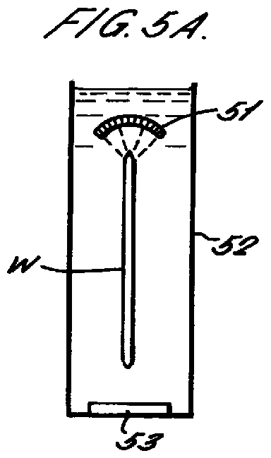
- FIG. 5A is a side view of a second embodiment of the
inventive megasonic cleaning apparatus;
- FIG. 5B is a side view of the second embodiment of
the invention illustrated in FIG. 5A;
- FIG. 6A is a front view of a third embodiment of the
inventive megasonic cleaning apparatus; and
- FIG. 6B is a side view of the third embodiment of the
invention illustrated in FIG. 6A.
-
-
FIG. 2 is a front view of a megasonic cleaning tank
for which the inventive apparatus and method have been
developed. A megasonic cleaning apparatus, as detailed in U.S.
Patent application Serial No: 09/191,057, entitled "Method and
Apparatus for Cleaning the Edge of a Thin Disc", having a
filing date of November 11, 1998, and assigned to the present
assignee, includes a transducer 23, optimally having a length
which is substantially equal to the diameter of the wafer,
disposed at the bottom of tank 21 of the megasonic cleaning
apparatus 20. Above the transducer 23, a first wafer support
25 and a second wafer support 27 are positioned to vertically
support the wafer in line with the transducer 23. The wafer
supports 25 and 27 are rotatable, and each preferably comprises
a rotatable wheel having a v-shaped groove for supporting a
wafer with minimal contact. At least one of the wafer supports
25 and 27 is operatively coupled to a motor (not shown) for
causing the support to rotate, thereby rotating the wafer. A
stabilizing mechanism 28 is additionally included and
positioned so as to contact and stabilize the wafer to prevent
wobbling. Preferably the stabilizing mechanism 28 is off-set
from the wafer's vertical diameter so as not to block the flux
of transducer energy from reaching the center of the wafer. To
further minimize energy blockage the wafer supports 25 and 27
may be positioned just below the wafer's horizontal diameter.
-
In operation, a mechanical wafer handler 26 inserts
the wafer into the tank 21 and the wafer's edges are engaged by
the wafer supports 25 and 27 and the stabilizing mechanism 28.
Transducer 23 is energized (e.g., by an oscillating power
source, not shown) and begins oscillating at a megasonic rate.
Megasonic energy is therefore coupled to the fluid resulting
in cavitation in the fluid. The oscillating cavitations, or
bubbles in the fluid gently clean the wafer. The acoustic
field results in acoustic streaming, which helps to transport
removed particles out of the tank 21. The motor (not shown),
coupled to at least one of the wafer supports 25 and 27, is
energized and rotates the at least one wafer support 25 and/or
27, causing the wafer to rotate. As the wafer rotates, as much
as nearly 50 percent of the wafer's edge surface may be
contacted by megasonic energy from the transducer 23 at any
given time, due to the fact that the length of the transducer
is approximately equal to the diameter of the wafer. It has
been observed, however, that there is a substantial amount of
transducer energy which is wasted as it is directed past the
wafer.
-
FIG. 3 illustrates a side view of an improvement to
megasonic cleaning, which is found in U.S. Patent Application
Serial No. 09/191,060, entitled "Improved Megasonic Cleaner",
filed on November 11, 1998, and assigned to the present
assignee. In that application, of which the present application
is a continuation-in-part, a transducer assembly is employed
which comprises a transducer 33 operatively coupled in angular
relationship to a focusing element 34. Transducer energy from
transducer 33 is focused by focusing element 34 into line 36
which is scanned along the wafer's surface. Preferably to scan
the energy across the wafer, the wafer W is rotated and/or
oscillated in the vertical direction by a mechanism (not shown)
such that point on the wafer surface receives the concentrated
energy.
-
FIG. 4 is a side view of a first embodiment of the
inventive megasonic cleaning apparatus. The embodiment
illustrated in FIG. 4 provides a single focal point reflector
41 immersed in the fluid and positioned to concentrate all
reflected energy originating at transducer 43 to one point 47
on the surface of wafer W in tank 42. As illustrated, the
single focal point reflector 41 is preferably a paraboloid
reflector having a width which is greater than that of the
wafer and limited only by the dimensions of the tank. The
reflector width is optimized to effectively collect whatever
transducer-generated energy passes the wafer. The length of a
single focal point paraboloid reflector 41 is limited only by
the curvature necessary to provide redirection of energy to the
same focal point from all positions on the reflector.
-
In operation, transducer 43 is activated and,
consequently, the fluid within tank 42 is energized, with the
energy being directed upward toward the wafer W. A percentage
of the energy passes the wafer, often with no cleaning benefit.
That energy which has passed the wafer will strike reflector
41 and be redirected to a single point 47 on the wafer's edge.
In this way, point 47 on the wafer's edge, which receives only
a fraction of the transducer-generated direct cleaning energy,
will receive concentrated reflected cleaning energy (i.e.,
cleaning energy which has not passed the wafer). Moreover, as
the wafer is rotated by the rotating mechanism (not shown),
adjacent points on the wafer's edge may be cleaned
simultaneously by a plurality of single point reflectors. For
instance, the curvature of reflector 41 provides for optimal
concentration of energy at the point 47 on the wafer's edge;
however, the width of such a reflector may be less than the
diameter of the wafer, thereby allowing other unfocussed
energy, which has passed the wafer, to remain uncollected. It
may, therefore, be desirable to provide a plurality of single
focal point reflectors for focussing at a plurality of single
points on the wafer's edge.
-
FIG. 5A is a side view of an alternative embodiment
of the inventive megasonic cleaning apparatus wherein a
parabolic reflector 51 is positioned above the wafer W, and is
submerged in fluid disposed in tank 52. The parabolic
reflector 51 has a width which is greater than that of the
wafer, and is limited only by the width of the tank 52. The
reflector width is, as above, optimized to effectively collect
energy produced by transducer 53, which otherwise would have
been wasted or may reflect from the fluid surface in a random
manner and interfere with the direct cleaning energy emitted by
the transducer 53. The length of the parabolic reflector 51 is
preferably approximately equal to the diameter of the wafer W
to maximize the number of points along the perimeter of the
wafer that will receive the redirected energy at any given
time.
-
The front view of FIG. 5B illustrates that the shape
of the complex parabolic reflector 51 is customized, whereby
the focal point is varied along the length of the reflector 51
so that reflected energy is focussed on a plurality of points
along the wafer's edge. Accordingly, the curvature of the
parabola 51 at each of locations 54-59 differs to provide
different focal points for energy which strikes the reflector
at each of those different locations. While, for the sake of
illustration, six (6) different reflector locations are shown
as directing reflected energy to six different points on a
wafer, it will be understood by one having skill in the art
that any number of locations having different focal points may
be fabricated on a complex parabolic reflector and thus, the
focal points may be adjusted in a continuum so as to
simultaneously focus energy to each point along a portion of
the wafer's edge. In the illustrated apparatus, transducer 53
is positioned at the bottom of tank 52. The length of the
transducer 53 is preferably at least the same as the diameter
of the wafer, to ensure that all wafer surfaces can be exposed
to the sonic energy.
-
In operation, transducer 53 is activated and the
fluid within tank 52 is energized, with the energy being
directed upward toward the wafer W. A percentage of the energy
passes the wafer, often with no cleaning benefit. That energy
which has passed the wafer will strike reflector 51 and be
redirected to points on the wafer's edge. Specifically, energy
striking the reflector at location 54, will be redirected to
point 84 on the wafer's edge. Similarly, energy arriving at
locations 55-59 will be focussed respectively at points 85-89,
along the wafer's edge. In this way, a plurality of points 54-59
on the wafer's edge, which would otherwise have received
only a fraction of the direct transducer-generated cleaning
energy, receive concentrated reflected cleaning energy.
Moreover, as the wafer is rotated by the rotating mechanism
(not shown), the entire perimeter of the wafer's edge will be
cleaned.
-
FIG. 6A provides a side view illustration of an
alternative embodiment of the present invention comprising a
simple and inexpensive parabola 61. Parabolic reflector 61 is
a simple reflector having a fixed curvature which results in a
constant focal length along the length 66 of the reflector.
The parabolic reflector 61 is positioned above the wafer W
which is submerged in fluid disposed within tank 62. The wafer
is rotated within tank 62 to be cleaned by the fluid energized
by transducer 63. As depicted in the side view of FIG. 6B,
energy from transducer 63 which passes the wafer W will contact
the parabolic reflector 61 at various locations along its
length 66. Due to the fact that the reflector 61's curvature
is fixed, energy striking the reflector 61 at any location
along its length 66 will be focussed in a cord, or line 67, a
fixed distance from the reflector. Points 68 and 69 along the
wafer's edge will be cleaned by the focussed energy, as will
all points on the wafer's surface which are located along the
cord 67.
-
The foregoing description discloses only the
preferred embodiments of the invention, modifications of the
above-disclosed apparatus and method which fall within the
scope of the invention will be readily apparent to those having
ordinary skill in the art. For instance, a plurality of
reflectors, preferably parabolic or paraboloid reflectors, may
be employed for collecting energy generated by one or a
plurality of transducers. Furthermore, the location of the
parabolic or paraboloid reflectors may be modified to optimize
collection and redirection of wasted energy to the wafer's
edges, depending on the preferred location and orientation of
the transducer(s). Redirection of energy which has been
reflected at the tank surfaces (sidewalls, etc.) or at the
fluid surface, in addition to the redirection of passing energy
by strategically positioned reflectors, can further optimize
the energy efficiency of megasonic cleaning. A combination of
reflectors for directing sonic energy to a wafer, for
redirecting passing sonic energy and for redirecting reflected
sonic energy is additionally contemplated. The reflectors may
be positioned vertically beside the wafer's edge, rather than
above the wafer's edge in which case they might receive
cleaning energy form a transducer positioned along the opposite
side wall of the tank. In such an embodiment the wafer would
not need to be completely submerged. The reflectors may be
used in embodiments such as those described with reference to
FIG. 3, in which case the reflector is positioned along the
backside of the wafer to receive cleaning energy which travels
through the major surface of the wafer and to direct the
cleaning energy to the wafer's edge. In sum, the inventively
employed reflectors can be advantageously used within virtually
any megasonic tank type cleaner. Therefore, it will be
understood by those of ordinary skill in the art, that the
embodiments provided herein are merely exemplary of the
presently preferred embodiments of the invention, and the
invention is not to be limited thereby. Similarly, it will be
understood that cleaning energy may contact the wafer
preferably assisting in cleaning thereof, and then continue
past the wafer. Thus the term passing sonic energy refers to
energy which passes the wafer and in doing so may or may not
contact the wafer. Finally, it will be understood that a
single focal point may include an area of adjacent points, and
that any reflector which focuses rays to a focal point may be
employed, although a reflector which focuses parallel rays to a
focal point (e.g., a parabolic or paraboloid reflector) is
preferred.
-
Accordingly, while the present invention has been
disclosed in connection with the preferred embodiments thereof,
it should be understood that other embodiments may fall within
the spirit and scope of the invention, as defined by the
following claims.